EP2746868A1 - Barillet d'horlogerie - Google Patents
Barillet d'horlogerie Download PDFInfo
- Publication number
- EP2746868A1 EP2746868A1 EP12197746.6A EP12197746A EP2746868A1 EP 2746868 A1 EP2746868 A1 EP 2746868A1 EP 12197746 A EP12197746 A EP 12197746A EP 2746868 A1 EP2746868 A1 EP 2746868A1
- Authority
- EP
- European Patent Office
- Prior art keywords
- ratchet
- shaft
- drum
- bridge
- spring
- Prior art date
- Legal status (The legal status is an assumption and is not a legal conclusion. Google has not performed a legal analysis and makes no representation as to the accuracy of the status listed.)
- Granted
Links
- 230000000295 complement effect Effects 0.000 claims abstract description 5
- 239000004575 stone Substances 0.000 claims description 17
- XEEYBQQBJWHFJM-UHFFFAOYSA-N Iron Chemical compound [Fe] XEEYBQQBJWHFJM-UHFFFAOYSA-N 0.000 claims description 6
- PXHVJJICTQNCMI-UHFFFAOYSA-N Nickel Chemical compound [Ni] PXHVJJICTQNCMI-UHFFFAOYSA-N 0.000 claims description 6
- 238000006073 displacement reaction Methods 0.000 claims description 4
- VYZAMTAEIAYCRO-UHFFFAOYSA-N Chromium Chemical compound [Cr] VYZAMTAEIAYCRO-UHFFFAOYSA-N 0.000 claims description 3
- ZOKXTWBITQBERF-UHFFFAOYSA-N Molybdenum Chemical compound [Mo] ZOKXTWBITQBERF-UHFFFAOYSA-N 0.000 claims description 3
- RTAQQCXQSZGOHL-UHFFFAOYSA-N Titanium Chemical compound [Ti] RTAQQCXQSZGOHL-UHFFFAOYSA-N 0.000 claims description 3
- 239000000956 alloy Substances 0.000 claims description 3
- 229910045601 alloy Inorganic materials 0.000 claims description 3
- 229910052790 beryllium Inorganic materials 0.000 claims description 3
- ATBAMAFKBVZNFJ-UHFFFAOYSA-N beryllium atom Chemical compound [Be] ATBAMAFKBVZNFJ-UHFFFAOYSA-N 0.000 claims description 3
- 229910052804 chromium Inorganic materials 0.000 claims description 3
- 239000011651 chromium Substances 0.000 claims description 3
- SZMZREIADCOWQA-UHFFFAOYSA-N chromium cobalt nickel Chemical compound [Cr].[Co].[Ni] SZMZREIADCOWQA-UHFFFAOYSA-N 0.000 claims description 3
- 239000010941 cobalt Substances 0.000 claims description 3
- 229910017052 cobalt Inorganic materials 0.000 claims description 3
- GUTLYIVDDKVIGB-UHFFFAOYSA-N cobalt atom Chemical compound [Co] GUTLYIVDDKVIGB-UHFFFAOYSA-N 0.000 claims description 3
- 229910052742 iron Inorganic materials 0.000 claims description 3
- 229910052750 molybdenum Inorganic materials 0.000 claims description 3
- 239000011733 molybdenum Substances 0.000 claims description 3
- 229910052759 nickel Inorganic materials 0.000 claims description 3
- 239000010936 titanium Substances 0.000 claims description 3
- 229910052719 titanium Inorganic materials 0.000 claims description 3
- WFKWXMTUELFFGS-UHFFFAOYSA-N tungsten Chemical compound [W] WFKWXMTUELFFGS-UHFFFAOYSA-N 0.000 claims description 3
- 229910052721 tungsten Inorganic materials 0.000 claims description 3
- 239000010937 tungsten Substances 0.000 claims description 3
- BASFCYQUMIYNBI-UHFFFAOYSA-N platinum Chemical compound [Pt] BASFCYQUMIYNBI-UHFFFAOYSA-N 0.000 claims 2
- 229910052697 platinum Inorganic materials 0.000 claims 1
- 230000007246 mechanism Effects 0.000 description 4
- 239000010935 stainless steel Substances 0.000 description 3
- 229910001220 stainless steel Inorganic materials 0.000 description 3
- 238000004146 energy storage Methods 0.000 description 2
- 239000000463 material Substances 0.000 description 2
- -1 "Nivaflex®" Substances 0.000 description 1
- 229910000975 Carbon steel Inorganic materials 0.000 description 1
- 229910000831 Steel Inorganic materials 0.000 description 1
- 239000011324 bead Substances 0.000 description 1
- 239000010962 carbon steel Substances 0.000 description 1
- 239000011521 glass Substances 0.000 description 1
- 238000003754 machining Methods 0.000 description 1
- 238000004519 manufacturing process Methods 0.000 description 1
- 239000010453 quartz Substances 0.000 description 1
- 238000011084 recovery Methods 0.000 description 1
- 229910052710 silicon Inorganic materials 0.000 description 1
- 239000010703 silicon Substances 0.000 description 1
- VYPSYNLAJGMNEJ-UHFFFAOYSA-N silicon dioxide Inorganic materials O=[Si]=O VYPSYNLAJGMNEJ-UHFFFAOYSA-N 0.000 description 1
- 238000004513 sizing Methods 0.000 description 1
- 239000010959 steel Substances 0.000 description 1
Images
Classifications
-
- G—PHYSICS
- G04—HOROLOGY
- G04B—MECHANICALLY-DRIVEN CLOCKS OR WATCHES; MECHANICAL PARTS OF CLOCKS OR WATCHES IN GENERAL; TIME PIECES USING THE POSITION OF THE SUN, MOON OR STARS
- G04B1/00—Driving mechanisms
- G04B1/10—Driving mechanisms with mainspring
- G04B1/16—Barrels; Arbors; Barrel axles
-
- G—PHYSICS
- G04—HOROLOGY
- G04B—MECHANICALLY-DRIVEN CLOCKS OR WATCHES; MECHANICAL PARTS OF CLOCKS OR WATCHES IN GENERAL; TIME PIECES USING THE POSITION OF THE SUN, MOON OR STARS
- G04B1/00—Driving mechanisms
- G04B1/10—Driving mechanisms with mainspring
- G04B1/14—Mainsprings; Bridles therefor
- G04B1/145—Composition and manufacture of the springs
-
- G—PHYSICS
- G04—HOROLOGY
- G04B—MECHANICALLY-DRIVEN CLOCKS OR WATCHES; MECHANICAL PARTS OF CLOCKS OR WATCHES IN GENERAL; TIME PIECES USING THE POSITION OF THE SUN, MOON OR STARS
- G04B1/00—Driving mechanisms
- G04B1/10—Driving mechanisms with mainspring
- G04B1/18—Constructions for connecting the ends of the mainsprings with the barrel or the arbor
-
- G—PHYSICS
- G04—HOROLOGY
- G04B—MECHANICALLY-DRIVEN CLOCKS OR WATCHES; MECHANICAL PARTS OF CLOCKS OR WATCHES IN GENERAL; TIME PIECES USING THE POSITION OF THE SUN, MOON OR STARS
- G04B1/00—Driving mechanisms
- G04B1/10—Driving mechanisms with mainspring
- G04B1/14—Mainsprings; Bridles therefor
Definitions
- the invention relates to a watch cylinder for pivotally mounting between a plate and a bridge and comprising at least one spring housed between a pivoting drum and a cover and hung between at its outer end said drum and at its inner end a shaft which is integral in pivoting with a ratchet around a pivot axis.
- the invention also relates to a watch movement, comprising at least one plate and a bridge and such a cylinder.
- the invention also relates to a watch comprising such a movement.
- the invention relates to the field of watch mechanisms, and more particularly the energy storage mechanisms, the engine barrel type, barrel striking, or the like.
- a solution consists of in a decrease in the diameter of the barrel shaft and the associated core, so as to increase the space available in the drum for the spring.
- the ratio of the bead radius to the thickness of the spring is usually between 10 and 20, and the invention proposes to lower this ratio below 10, and preferably in the range between 5 and 10.
- the dimensioning should not be done lightly, indeed a risk of breakage exists if the bung diameter is too small.
- a ratchet is mounted axially on a barrel axis or on a bung, via a square, the ratchet being generally fixed by an axial screw.
- the size of this screw and that of the square thus condition a minimum diameter of a pivoting surface.
- a Shoulder joined to this pivoting surface limits axial fretting of the shaft or the bung relative to a plate or a bridge carrying a stone or the like.
- the invention proposes to improve the design of barrels designed for a large power reserve, giving them good rigidity, particularly at the ratchet, while retaining a reduced number of components, and an acceptable machining cost, or, preferably, more economical than on known barrels.
- the invention thus relates to a watch cylinder for pivotally mounting between a plate and a bridge and comprising at least one spring housed between a pivoting drum and a cover and hung between at its outer end said drum and at its inner end a shaft.
- said shaft comprises, around a cylindrical shaft according to said pivot axis, on the one hand a hook projecting for the attachment of said spring, and on the other hand pivoting drive means, projecting or reentrant, which cooperate with complementary drive means that includes said ratchet for its pivoting drive.
- said pivoting drive means constitute an axial abutment of said ratchet along said pivot axis
- said shaft is pivoted at an upper bearing surface in a bore of said bridge or a stone which comprises said bridge
- said ratchet comprises an upper support net whose travel is limited by a lower surface of said bridge 5 or said stone, said ratchet being between said bridge and an upper surface that comprises said drum facing a lower surface said ratchet, and said drum pivots at a bore it comprises on said cylindrical barrel.
- said spring comprises, in the axial direction of said pivot axis, a projecting upper portion arranged to bear on an inner surface of said drum, and a lower projecting portion arranged to come into support on an upper part of said cover.
- the fretting of said drum is limited in lower bearing relative to said ratchet by an upper surface of said drum which is limited by a lower surface of said ratchet, the fretting of said ratchet being limited in lower bearing relative to at said bridge, by a thread of said ratchet which is bounded by a lower surface of said bridge or of a stone which said bridge comprises, and the step of said lid is limited in upper support relative to said plate, by a lower surface of said lid; which is limited by an upper surface of said platen or a stone that includes said platen.
- said spring is made of a cobalt-nickel-chromium-based multiphase alloy comprising from 44 to 46% of cobalt, from 20 to 22% of nickel and from 17 to 19% of chromium. , from 4 to 6% of iron, from 3 to 5% of tungsten, from 3 to 5% of molybdenum, from 0 to 2% of titanium, from 0 to 1% of beryllium, and from Young's modulus of between 200 and 240 GPa and a shear modulus of between 80 and 100 GPa, in said spring has a width / thickness ratio of between 3 and 23, and the ratio of the maximum radius of a bearing surface of the spring of said shaft and the the thickness of said spring is between 3 and 9.
- the invention also relates to a watch movement, comprising at least one plate and a bridge and such a cylinder.
- said bridge comprises an upper abutment plate whose lower surface is arranged to limit the axial displacement of said shaft, and said platen comprises a lower abutment plate whose upper surface is arranged to limit the axial movement of said shaft.
- the invention also relates to a watch comprising such a movement.
- the invention relates to the field of watch mechanisms, and more particularly the energy storage mechanisms, the engine barrel type, barrel striking, or the like.
- the invention thus relates to a watch cylinder 1 for pivotally mounting between a plate 9 and a bridge 5, and comprising at least one spring 7.
- This spring 7 is housed between a pivoting drum 6 and a cover 8, and hooked between, at its outer end the drum 6 and at its inner end a shaft 3.
- the shaft 3 is pivotally integral with a ratchet 2 about a pivot axis D.
- the shaft 3 comprises, around a cylindrical shaft 31 along the axis of pivoting D, on the one hand a hook 32 projecting for the attachment of the spring 7, and on the other hand means of pivoting drive 42, projecting or reentrant, which cooperate with complementary drive means 23 that includes the ratchet 2 for its pivoting drive.
- the drive means 42 may conventionally consist of a square or plates. In a material-saving version, they are re-entrant, for example constituted by two plates in a groove of the shaft 3, the complementary means 23 of the ratchet 2 can then advantageously consist of at least one leaf spring allowing the introduction of the ratchet 2 on the shaft 3, and also ensuring the pivoting drive.
- pivoting drive means 42 constitute an axial stop of the ratchet 2 along the pivot axis D.
- the shaft 3 is pivoted at a upper span 13 in a bore 51 of the bridge 5 or a stone 52 that includes the bridge 5.
- the ratchet 2 preferably comprises, so as to reduce the friction torque and the yield loss, at least one upper thread d support 24 whose stroke is limited by a lower surface 53 of the bridge 5 or the stone 52 (as shown in the figures).
- the ratchet 2 is between the bridge 5 and an upper surface 61 that includes the drum 6 facing a lower surface 22 of the ratchet 2.
- the drum 6 pivots at a bore 62 that it has on the cylindrical shaft 31 .
- the spring 7 comprises, in the axial direction of the pivot axis D, a projecting upper portion 71 arranged to bear on an inner surface 65 of the drum 6, and a projecting lower portion 72 arranged to bear on a upper part 85 of the cover 8. The return of frolicking of the shaft 3 is thus ensured by the spring 7.
- the drum 6 carries a cover 8, preferably but not necessarily pivotally attached to the drum 6, and a bore 81 cooperates with a bearing 31 of the shaft 3.
- a lower surface 82 of the cover 8 is limited in clearance by a surface upper 93 of the plate 9 or a stone 92 housed in the plate 9, a bore 91 of the plate 9 or the stone 92 serving as a pivot to the bearing 31 of the shaft 3.
- the frolicking of the drum 6 is limited to lower bearing relative to the ratchet 2 by an upper surface 61 of the drum 6 which is limited by a lower surface 22 of the ratchet 2.
- the fretting of the ratchet 2 is limited in lower bearing relative to the bridge 5, by a thread 24 of the ratchet 2 which is limited by a lower surface 53 of the bridge 5 or a stone 52 that includes the bridge 5.
- the frog of the cover 8 is limited in upper support relative to the plate 9 , by a lower surface 82 of the cover 8 which is limited by an upper surface 93 of the plate 9 or a stone 91 that comprises the plate 9.
- the motor spring can be made of different materials: carbon steel, stainless steel, "Nivaflex®", silicon, DLC, quartz, glass, or similar.
- the spring 7 is made of a cobalt-nickel-chromium-based multiphase alloy comprising from 44 to 46% of cobalt, from 20 to 22% of nickel, from 17 to 19% of chromium, from 4 to 6% of iron, 3 to 5% of tungsten, 3 to 5% of molybdenum, 0 to 2% of titanium, 0 to 1% of beryllium, and Young's modulus of between 200 and 240 GPa and a shear modulus between 80 and 100 GPa.
- This spring 7 preferably has a width / thickness ratio of between 3 and 23, and more particularly between 9 and 21.
- the maximum radius of the bearing 31 of the shaft 3 (without taking into account the possible extra thickness specific to a hook 32), made of steel or stainless steel, for example hardened stainless steel 4C27A (also named according to different standards 1.4197, ASTM 420F, or DIN X22 CrMoNiS 13 1), relative to the pivot axis D is less than nine times the maximum thickness of the spring 7.
- the embodiments illustrated make it possible to obtain a ratio between the maximum radius the bearing 31 of the shaft 3 and the thickness of the spring 7 between 3 and 9, and preferably between 4 and 6, preferably close to five.
- the invention also relates to a watch movement 100, comprising at least one plate 9 and a bridge 5 and such a cylinder 1.
- the bridge 5 may comprise at least one thread intended to cooperate in support, with the least possible contact surface , with the upper surface 21 of the ratchet 2, in addition to or in place of the thread 24 of the ratchet 2.
- the bridge 5 comprises an upper stop plate 56, fixed with screws or rivets 58, or glued or welded, or the like, a lower surface 57 is arranged to limit the axial displacement of the shaft 3, and the plate 9 comprises a lower abutment plate 96, fixed with screws or rivets 98, or bonded or welded, or the like, an upper surface 97 of which is arranged to limit the axial displacement of the shaft 3.
- the invention also relates to a watch 200 comprising such a movement 100.
- the first variant of the figure 1 is advantageous the shaft 3 is of substantially constant diameter, the hook 32 is easy to machine, the drive means 42 also.
- the bung diameter is limited only by the bulk of these pivoting drive means 42.
- the second variant of the figure 2 ensures the recovery of frolicking of the shaft 3 with the spring 7, the shaft 3 adopts the same advantageous configuration at low production cost as in the first variant.
- the bung diameter is limited by the dimensions of the drive means 42, typically a square or the like.
Landscapes
- Physics & Mathematics (AREA)
- General Physics & Mathematics (AREA)
- Engineering & Computer Science (AREA)
- Metallurgy (AREA)
- Adornments (AREA)
- Springs (AREA)
Abstract
Description
- L'invention concerne un barillet d'horlogerie pour montage pivotant entre une platine et un pont et comportant au moins un ressort logé entre un tambour pivotant et un couvercle et accroché entre, à son extrémité extérieure ledit tambour et à son extrémité intérieure un arbre lequel est solidaire en pivotement avec un rochet autour d'un axe de pivotement.
- L'invention concerne encore un mouvement d'horlogerie, comportant au moins une platine et un pont et un tel barillet.
- L'invention concerne encore une montre comportant un tel mouvement.
- L'invention concerne le domaine des mécanismes d'horlogerie, et plus particulièrement les mécanismes de stockage d'énergie, du type barillet moteur, barillet de sonnerie, ou similaire.
- Pour augmenter la réserve de marche, par augmentation du nombre de tours d'un ressort de barillet, fixé à son extrémité intérieure sur une bonde constituée, ou bien par un arbre, généralement cylindrique, ou bien par un noyau plus massif, une solution consiste en une diminution du diamètre de l'arbre de barillet et du noyau associé, de façon à augmenter la place disponible dans le tambour pour le ressort.
- Le rapport du rayon de bonde par rapport à l'épaisseur du ressort est usuellement compris entre 10 et 20, et l'invention se propose d'abaisser ce rapport en-dessous de 10, et préférentiellement dans la plage comprise entre 5 et 10.
- Le dimensionnement ne doit pas être fait à la légère, en effet un risque de casse existe si le diamètre de bonde est trop faible.
- Dans l'architecture classique des barillets, un rochet est monté axialement sur un axe de barillet ou sur une bonde, par l'intermédiaire d'un carré, le rochet étant généralement fixé par une vis axiale. La dimension de cette vis et celle du carré conditionnent donc un diamètre minimal d'une portée de pivotement. Un épaulement jointif à cette portée de pivotement limite l'ébat axial de l'arbre ou de la bonde par rapport à une platine ou à un pont porteur d'une pierre ou similaire.
- On ne peut en particulier pas se contenter de réduire l'ensemble des dimensionnements, car les sections de matière sont alors insuffisantes pour assurer la tenue en fatigue.
- Il s'agit donc de concilier un diamètre d'arbre le plus réduit possible, pour autoriser la plus grande réserve de marche possible, et une rigidité de l'entraînement du rochet.
- L'invention se propose d'améliorer la conception de barillets conçus pour une grande réserve de marche, en leur procurant une bonne rigidité, notamment au niveau du rochet, tout en conservant un nombre de composants réduit, et un coût d'usinage acceptable, ou, de préférence, plus économique que sur les barillets connus.
- L'invention concerne ainsi un barillet d'horlogerie pour montage pivotant entre une platine et un pont et comportant au moins un ressort logé entre un tambour pivotant et un couvercle et accroché entre, à son extrémité extérieure ledit tambour et à son extrémité intérieure un arbre lequel est solidaire en pivotement avec un rochet autour d'un axe de pivotement, caractérisé en ce que ledit arbre comporte, autour d'un fût cylindrique selon ledit axe de pivotement, d'une part un crochet saillant pour l'accrochage dudit ressort, et d'autre part des moyens d'entraînement en pivotement, saillants ou rentrants, qui coopèrent avec des moyens d'entraînement complémentaire que comporte ledit rochet pour son entraînement en pivotement.
- Selon une caractéristique de l'invention, lesdits moyens d'entraînement en pivotement constituent une butée axiale dudit rochet selon ledit axe de pivotement, ledit arbre est pivoté au niveau d'une portée supérieure dans un alésage dudit pont ou d'une pierre que comporte ledit pont, et ledit rochet comporte un filet supérieur d'appui dont la course est limitée par une surface inférieure dudit pont 5 ou de ladite pierre, ledit rochet étant compris entre ledit pont et une surface supérieure que comporte ledit tambour face à une surface inférieure dudit rochet, et ledit tambour pivote au niveau d'un alésage qu'il comporte sur ledit fût cylindrique.
- Selon une caractéristique de l'invention dans une variante particulière, ledit ressort comporte, selon la direction axiale dudit axe de pivotement, une partie supérieure saillante agencée pour venir en appui sur une surface intérieure dudit tambour, et une partie inférieure saillant agencée pour venir en appui sur une partie supérieure dudit couvercle.
- Selon une caractéristique de l'invention, l'ébat dudit tambour est limité en appui inférieur par rapport audit rochet par une surface supérieure dudit tambour qui est limitée par une surface inférieure dudit rochet, l'ébat dudit rochet est limité en appui inférieur par rapport audit pont, par un filet dudit rochet qui est limité par une surface inférieure dudit pont ou d'une pierre que comporte ledit pont, et l'ébat dudit couvercle est limité en appui supérieur par rapport à ladite platine, par une surface inférieure dudit couvercle qui est limitée par une surface supérieure de ladite platine ou d'une pierre que comporte ladite platine.
- Selon une autre caractéristique encore de l'invention, ledit ressort est réalisé dans un alliage multiphasé à base cobalt-nickel-chrome, comportant de 44 à 46% de cobalt, de 20 à 22% de nickel, de 17 à 19% de chrome, de 4 à 6% de fer, de 3 à 5% de tungstène, de 3 à 5% de molybdène, de 0 à 2% de titane, de 0 à 1% de béryllium, et de module d'Young compris entre 200 et 240 GPa et un module de cisaillement compris entre 80 et 100 GPa, en ledit ressort a un rapport largeur/épaisseur compris entre 3 et 23, et le rapport entre le rayon maximal d'une portée d'appui du ressort dudit arbre et l'épaisseur dudit ressort est compris entre 3 et 9.
- L'invention concerne encore un mouvement d'horlogerie, comportant au moins une platine et un pont et un tel barillet.
- Selon une caractéristique de l'invention dans une variante particulière, ledit pont comporte une plaque de butée supérieure dont une surface inférieure est agencée pour limiter le débattement axial dudit arbre, et ladite platine comporte une plaque de butée inférieure dont une surface supérieure est agencée pour limiter le débattement axial dudit arbre.
- L'invention concerne encore une montre comportant un tel mouvement.
- D'autres caractéristiques et avantages de l'invention apparaîtront à la lecture de la description détaillée qui va suivre, en référence aux dessins annexés, où :
- la
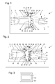
figure 1 représente, de façon schématisée et en coupe par son axe de pivotement, un barillet selon une première variante de l'invention ; - la
figure 2 représente, de façon schématisée et en coupe par son axe de pivotement, un barillet selon une deuxième variante de l'invention ; - la
figure 3 représente, de façon schématisée en blocs, une pièce d'horlogerie comportant un mouvement comportant lui-même un barillet selon l'invention. - L'invention concerne le domaine des mécanismes d'horlogerie, et plus particulièrement les mécanismes de stockage d'énergie, du type barillet moteur, barillet de sonnerie, ou similaire.
- L'invention concerne ainsi un barillet d'horlogerie 1 pour montage pivotant entre une platine 9 et un pont 5, et comportant au moins un ressort 7. Ce ressort 7 est logé entre un tambour 6 pivotant et un couvercle 8, et accroché entre, à son extrémité extérieure le tambour 6 et à son extrémité intérieure un arbre 3. L'arbre 3 est solidaire en pivotement avec un rochet 2 autour d'un axe de pivotement D.
- Selon l'invention, l'arbre 3 comporte, autour d'un fût cylindrique 31 selon l'axe de pivotement D, d'une part un crochet 32 saillant pour l'accrochage du ressort 7, et d'autre part des moyens d'entraînement en pivotement 42, saillants ou rentrants, qui coopèrent avec des moyens d'entraînement complémentaire 23 que comporte le rochet 2 pour son entraînement en pivotement. Les moyens d'entraînement 42 peuvent consister classiquement en un carré ou des plats. Dans une version économe en matière, ils sont rentrants, par exemple constitués par deux plats dans une gorge de l'arbre 3, les moyens complémentaires 23 du rochet 2 peuvent alors avantageusement consister en au moins une lame de ressort autorisant l'introduction du rochet 2 sur l'arbre 3, et assurant également l'entraînement en pivotement.
- Ces moyens d'entraînement en pivotement 42 constituent une butée axiale du rochet 2 selon l'axe de pivotement D. L'arbre 3 est pivoté au niveau d'une portée supérieure 13 dans un alésage 51 du pont 5 ou d'une pierre 52 que comporte ce pont 5. Et le rochet 2 comporte de préférence, de façon à réduire le couple de frottement et la perte de rendement, au moins un filet supérieur d'appui 24 dont la course est limitée par une surface inférieure 53 du pont 5 ou de la pierre 52 (comme représenté sur les figures). Le rochet 2 est compris entre le pont 5 et une surface supérieure 61 que comporte le tambour 6 face à une surface inférieure 22 du rochet 2. Et le tambour 6 pivote au niveau d'un alésage 62 qu'il comporte sur le fût cylindrique 31.
- Dans la deuxième variante de la
figure 2 , le ressort 7 comporte, selon la direction axiale de l'axe de pivotement D, une partie supérieure saillante 71 agencée pour venir en appui sur une surface intérieure 65 du tambour 6, et une partie inférieure saillante 72 agencée pour venir en appui sur une partie supérieure 85 du couvercle 8. La reprise d'ébat de l'arbre 3 est ainsi assurée par le ressort 7. - Le tambour 6 porte un couvercle 8, de préférence mais non nécessairement solidaire en pivotement du tambour 6, et dont un alésage 81 coopère avec une portée 31 de l'arbre 3. Une surface inférieure 82 du couvercle 8 est limitée en débattement par une surface supérieure 93 de la platine 9 ou d'une pierre 92 logée dans la platine 9, un alésage 91 de la platine 9 ou de la pierre 92 servant de pivot à la portée 31 de l'arbre 3.
- L'ébat du tambour 6 est limité en appui inférieur par rapport au rochet 2 par une surface supérieure 61 du tambour 6 qui est limitée par une surface inférieure 22 du rochet 2. L'ébat du rochet 2 est limité en appui inférieur par rapport au pont 5, par un filet 24 du rochet 2 qui est limité par une surface inférieure 53 du pont 5 ou d'une pierre 52 que comporte le pont 5. L'ébat du couvercle 8 est limité en appui supérieur par rapport à la platine 9, par une surface inférieure 82 du couvercle 8 qui est limitée par une surface supérieure 93 de la platine 9 ou d'une pierre 91 que comporte la platine 9.
- Le ressort moteur peut être réalisé en différents matériaux : acier au carbone, acier inoxydable, « Nivaflex® », silicium, DLC, quartz, verre, ou similaire. Dans une application particulière, le ressort 7 est réalisé dans un alliage multiphasé à base cobalt-nickel-chrome, comportant de 44 à 46% de cobalt, de 20 à 22% de nickel, de 17 à 19% de chrome, de 4 à 6% de fer, de 3 à 5% de tungstène, de 3 à 5% de molybdène, de 0 à 2% de titane, de 0 à 1% de béryllium, et de module d'Young compris entre 200 et 240 GPa et un module de cisaillement compris entre 80 et 100 GPa. Ce ressort 7 a de préférence un rapport largeur/épaisseur compris entre 3 et 23, et plus particulièrement entre 9 et 21.
- Et le rayon maximal de la portée 31 de l'arbre 3 (sans tenir compte de la surépaisseur éventuelle propre à un crochet 32), réalisé en acier ou en acier inoxydable, par exemple en acier inoxydable trempable 4C27A (aussi dénommé selon les différentes normes 1.4197, ASTM 420F, ou DIN X22 CrMoNiS 13 1), par rapport à l'axe de pivotement D est inférieur à neuf fois l'épaisseur maximale du ressort 7. En particulier les réalisations illustrées permettent d'obtenir un rapport entre le rayon maximal de la portée 31 de l'arbre 3 et l'épaisseur du ressort 7 compris entre 3 et 9, et de préférence entre 4 et 6, de préférence voisin de cinq.
- L'invention concerne encore un mouvement 100 d'horlogerie, comportant au moins une platine 9 et un pont 5 et un tel barillet 1. Le pont 5 peut comporter au moins un filet destiné à coopérer en appui, avec la moindre surface de contact possible, avec la surface supérieure 21 du rochet 2, en complément ou à la place du filet 24 du rochet 2.
- Dans la première variante de la
figure 1 , le pont 5 comporte une plaque de butée supérieure 56, fixée avec des vis ou rivets 58, ou encore collée ou soudée, ou similaire, dont une surface inférieure 57 est agencée pour limiter le débattement axial de l'arbre 3, et la platine 9 comporte une plaque de butée inférieure 96, fixée avec des vis ou rivets 98, ou encore collée ou soudée, ou similaire, dont une surface supérieure 97 est agencée pour limiter le débattement axial de l'arbre 3. - L'invention concerne encore une montre 200 comportant un tel mouvement 100.
- En somme, la première variante de la
figure 1 , est avantageuse l'arbre 3 est de diamètre sensiblement constant, le crochet 32 est facile à usiner, les moyens d'entraînement 42 également. Le diamètre de bonde n'est limité que par l'encombrement de ces moyens d'entraînement en pivotement 42. - La deuxième variante de la
figure 2 assure la reprise d'ébat de l'arbre 3 avec le ressort 7, l'arbre 3 adopte la même configuration avantageuse à bas coût de production que dans la première variante. Le diamètre de bonde est limité par les dimensions des moyens d'entraînement 42, typiquement un carré ou similaire.
Claims (9)
- Barillet d'horlogerie (1) pour montage pivotant entre une platine (9) et un pont (5) et comportant au moins un ressort (7) logé entre un tambour (6) pivotant et un couvercle (8) et accroché entre, à son extrémité extérieure ledit tambour (6) et à son extrémité intérieure un arbre (3) lequel est solidaire en pivotement avec un rochet (2) autour d'un axe de pivotement (D), caractérisé en ce que ledit arbre (3) comporte, autour d'un fût cylindrique (31) selon ledit axe de pivotement (D), d'une part un crochet (32) saillant pour l'accrochage dudit ressort (7), et d'autre part des moyens d'entraînement en pivotement (42), saillants ou rentrants, qui coopèrent avec des moyens d'entraînement complémentaire (23) que comporte ledit rochet (2) pour son entraînement en pivotement.
- Barillet (1) selon la revendication 1, caractérisé en ce que lesdits moyens d'entraînement en pivotement (42) constituent une butée axiale dudit rochet (2) selon ledit axe de pivotement (D) en ce que ledit arbre (3) est pivoté au niveau d'une portée supérieure (13) dans un alésage (51) dudit pont (5) ou d'une pierre (52) que comporte ledit pont (5), et en ce que ledit rochet (2) comporte un filet supérieur d'appui (24) dont la course est limitée par une surface inférieure (53) dudit pont (5) ou de ladite pierre (52), ledit rochet (2) étant compris entre ledit pont (5) et une surface supérieure (61) que comporte ledit tambour (6) face à une surface inférieure (22) dudit rochet (2), et en ce que ledit tambour (6) pivote au niveau d'un alésage (62) qu'il comporte sur ledit fût cylindrique (31).
- Barillet (1) selon la revendication 1 ou 2, caractérisé en ce que ledit ressort (7) comporte, selon la direction axiale dudit axe de pivotement (D), une partie supérieure saillante (71) agencée pour venir en appui sur une surface intérieure (65) dudit tambour (6), et une partie inférieure saillante (72) agencée pour venir en appui sur une partie supérieure (85) dudit couvercle (8).
- Barillet (1) selon l'une des revendications précédentes, caractérisé en ce que ledit tambour (6) porte un couvercle (8) solidaire en pivotement dudit tambour (6) et dont un alésage (81) coopère avec ledit fût cylindrique (31) dudit arbre (3), et en ce qu'une surface inférieure (82) dudit couvercle (8) est limitée en débattement par une surface supérieure (93) de ladite platine (9) ou d'une pierre (92) logée dans ladite platine (9), un alésage (91) de ladite platine (9) ou de ladite pierre (92) servant de pivot audit fût cylindrique (31) dudit arbre (3).
- Barillet (1) selon l'une des revendications 1 à 4, caractérisé en ce que l'ébat dudit tambour (6) est limité en appui inférieur par rapport audit rochet (2) par une surface supérieure (61) dudit tambour (6) qui est limitée par une surface inférieure (22) dudit rochet (2), en ce que l'ébat dudit rochet (2) est limité en appui inférieur par rapport audit pont (5), par un filet (24) dudit rochet (2) qui est limité par une surface inférieure (53) dudit pont (5) ou d'une pierre (52) que comporte ledit pont (5), et en ce que l'ébat dudit couvercle (8) est limité en appui supérieur par rapport à ladite platine (9), par une surface inférieure (82) dudit couvercle (8) qui est limitée par une surface supérieure (93) de ladite platine (9) ou d'une pierre (91) que comporte ladite platine.
- Barillet (1) selon l'une des revendications précédentes, caractérisé en ce que ledit ressort (7) est réalisé dans un alliage multiphasé à base cobalt-nickel-chrome, comportant de 44 à 46% de cobalt, de 20 à 22% de nickel, de 17 à 19% de chrome, de 4 à 6% de fer, de 3 à 5% de tungstène, de 3 à 5% de molybdène, de 0 à 2% de titane, de 0 à 1% de béryllium, et de module d'Young compris entre 200 et 240 GPa et un module de cisaillement compris entre 80 et 100 GPa, en ce que ledit ressort (7) a un rapport largeur/épaisseur compris entre 3 et 23, et en ce que le rapport entre le rayon maximal d'une portée (31) d'appui du ressort dudit arbre (3) et l'épaisseur dudit ressort (7) est compris entre 3 et 9.
- Mouvement (100) d'horlogerie, comportant au moins une platine (9) et un pont (5) et un barillet (1) selon l'une des revendications précédentes.
- Mouvement (100) selon la revendication précédente, caractérisé en ce que ledit pont (5) comporte une plaque de butée supérieure (56) dont une surface inférieure (57) est agencée pour limiter le débattement axial dudit arbre (3), et en ce que ladite platine (9) comporte une plaque de butée inférieure (96) dont une surface supérieure (97) est agencée pour limiter le débattement axial dudit arbre (3).
- Montre (200) comportant un mouvement (100) selon la revendication 7 ou 8.
Priority Applications (7)
| Application Number | Priority Date | Filing Date | Title |
|---|---|---|---|
| EP12197746.6A EP2746868B1 (fr) | 2012-12-18 | 2012-12-18 | Barillet d'horlogerie |
| EP13779838.5A EP2936253B1 (fr) | 2012-12-18 | 2013-10-21 | Barillet d'horlogerie |
| CN201380066191.5A CN104885021B (zh) | 2012-12-18 | 2013-10-21 | 钟表发条盒 |
| US14/653,484 US9291999B2 (en) | 2012-12-18 | 2013-10-21 | Timepiece barrel |
| PCT/EP2013/071989 WO2014095126A1 (fr) | 2012-12-18 | 2013-10-21 | Barillet d'horlogerie |
| JP2015546908A JP6027693B2 (ja) | 2012-12-18 | 2013-10-21 | 時計の香箱 |
| HK16102157.7A HK1214374A1 (zh) | 2012-12-18 | 2016-02-25 | 鐘錶發條盒 |
Applications Claiming Priority (1)
| Application Number | Priority Date | Filing Date | Title |
|---|---|---|---|
| EP12197746.6A EP2746868B1 (fr) | 2012-12-18 | 2012-12-18 | Barillet d'horlogerie |
Publications (2)
| Publication Number | Publication Date |
|---|---|
| EP2746868A1 true EP2746868A1 (fr) | 2014-06-25 |
| EP2746868B1 EP2746868B1 (fr) | 2016-04-27 |
Family
ID=47552772
Family Applications (2)
| Application Number | Title | Priority Date | Filing Date |
|---|---|---|---|
| EP12197746.6A Active EP2746868B1 (fr) | 2012-12-18 | 2012-12-18 | Barillet d'horlogerie |
| EP13779838.5A Active EP2936253B1 (fr) | 2012-12-18 | 2013-10-21 | Barillet d'horlogerie |
Family Applications After (1)
| Application Number | Title | Priority Date | Filing Date |
|---|---|---|---|
| EP13779838.5A Active EP2936253B1 (fr) | 2012-12-18 | 2013-10-21 | Barillet d'horlogerie |
Country Status (6)
| Country | Link |
|---|---|
| US (1) | US9291999B2 (fr) |
| EP (2) | EP2746868B1 (fr) |
| JP (1) | JP6027693B2 (fr) |
| CN (1) | CN104885021B (fr) |
| HK (1) | HK1214374A1 (fr) |
| WO (1) | WO2014095126A1 (fr) |
Cited By (2)
| Publication number | Priority date | Publication date | Assignee | Title |
|---|---|---|---|---|
| EP2963504A1 (fr) * | 2014-06-30 | 2016-01-06 | Rolex Sa | Barillet pour pièce d'horlogerie |
| EP3067756A1 (fr) * | 2015-03-09 | 2016-09-14 | Nivarox-FAR S.A. | Ensemble pivotant pour une pièce d'horlogerie |
Families Citing this family (5)
| Publication number | Priority date | Publication date | Assignee | Title |
|---|---|---|---|---|
| CH711870B1 (fr) * | 2015-12-10 | 2019-08-30 | Parmigiani Fleurier S A | Mouvement horloger. |
| JP6753127B2 (ja) * | 2016-04-25 | 2020-09-09 | セイコーエプソン株式会社 | 時計用ムーブメントおよび時計 |
| JP7133909B2 (ja) * | 2016-07-04 | 2022-09-09 | ロレックス・ソシエテ・アノニム | 時計用組立体の製造方法、及び該製造方法により得られる時計用組立体 |
| EP3575885B1 (fr) * | 2018-06-01 | 2022-09-21 | Nivarox-FAR S.A. | Barillet d'horlogerie |
| EP3872576B1 (fr) * | 2020-02-25 | 2024-02-21 | ETA SA Manufacture Horlogère Suisse | Barillet d'horlogerie a arbre vrille |
Citations (8)
| Publication number | Priority date | Publication date | Assignee | Title |
|---|---|---|---|---|
| CH15286A (fr) * | 1897-09-15 | 1898-04-30 | Giuseppe Danasino | Mouvement de montre à ressort moteur perfectionné |
| US730103A (en) * | 1903-01-13 | 1903-06-02 | Lewis A Erickson | Watch-barrel. |
| GB647819A (en) * | 1944-12-12 | 1950-12-20 | Elgin Nat Watch Co | Cobalt chromium nickel base alloy |
| FR1034443A (fr) * | 1950-04-01 | 1953-07-23 | Ressort d'horlogerie inoxydable présentant une grande résistance à la fatigue et procédé pour sa fabrication | |
| FR1443494A (fr) * | 1965-06-10 | 1966-06-24 | Glashuetter Uhrenbetr E Veb | Barillet de ressort pour montres |
| FR2135134A1 (fr) * | 1971-05-05 | 1972-12-15 | Baumgartner Freres Sa | |
| FR2210784A1 (fr) * | 1972-12-18 | 1974-07-12 | Ebauchesfabrik Eta Ag | |
| FR2329000A1 (fr) * | 1975-10-21 | 1977-05-20 | Ebauchesfabrik Eta Ag | Arbre de barillet extractible pour mouvement de montre |
Family Cites Families (10)
| Publication number | Priority date | Publication date | Assignee | Title |
|---|---|---|---|---|
| US161236A (en) * | 1875-03-23 | Improvement in mainsprings for watches | ||
| DE148352C (fr) | ||||
| US163161A (en) * | 1875-05-11 | Improvement in mainsprings for watches | ||
| US174031A (en) * | 1876-02-22 | Improvement in safety device for mainsprings | ||
| US916123A (en) * | 1908-05-25 | 1909-03-23 | Vincent E Duncanson | Clock. |
| CH343891A (fr) | 1957-12-20 | 1959-12-31 | Revue Fabriques D Horlogerie T | Moteur de montre |
| GB1044852A (en) * | 1965-05-10 | 1966-10-05 | Glashutter Uhrenbetr E Veb | Spring barrel arrangements for watches |
| JPS50122264U (fr) * | 1974-03-22 | 1975-10-06 | ||
| JPS5188757U (fr) * | 1975-01-11 | 1976-07-15 | ||
| CH702994B1 (fr) * | 2010-04-26 | 2015-07-31 | Eterna Sa Fabrique D Horlogerie | Pièce d'horlogerie comprenant un barillet monté sur un pont de barillet. |
-
2012
- 2012-12-18 EP EP12197746.6A patent/EP2746868B1/fr active Active
-
2013
- 2013-10-21 CN CN201380066191.5A patent/CN104885021B/zh active Active
- 2013-10-21 EP EP13779838.5A patent/EP2936253B1/fr active Active
- 2013-10-21 US US14/653,484 patent/US9291999B2/en active Active
- 2013-10-21 WO PCT/EP2013/071989 patent/WO2014095126A1/fr active Application Filing
- 2013-10-21 JP JP2015546908A patent/JP6027693B2/ja active Active
-
2016
- 2016-02-25 HK HK16102157.7A patent/HK1214374A1/zh unknown
Patent Citations (8)
| Publication number | Priority date | Publication date | Assignee | Title |
|---|---|---|---|---|
| CH15286A (fr) * | 1897-09-15 | 1898-04-30 | Giuseppe Danasino | Mouvement de montre à ressort moteur perfectionné |
| US730103A (en) * | 1903-01-13 | 1903-06-02 | Lewis A Erickson | Watch-barrel. |
| GB647819A (en) * | 1944-12-12 | 1950-12-20 | Elgin Nat Watch Co | Cobalt chromium nickel base alloy |
| FR1034443A (fr) * | 1950-04-01 | 1953-07-23 | Ressort d'horlogerie inoxydable présentant une grande résistance à la fatigue et procédé pour sa fabrication | |
| FR1443494A (fr) * | 1965-06-10 | 1966-06-24 | Glashuetter Uhrenbetr E Veb | Barillet de ressort pour montres |
| FR2135134A1 (fr) * | 1971-05-05 | 1972-12-15 | Baumgartner Freres Sa | |
| FR2210784A1 (fr) * | 1972-12-18 | 1974-07-12 | Ebauchesfabrik Eta Ag | |
| FR2329000A1 (fr) * | 1975-10-21 | 1977-05-20 | Ebauchesfabrik Eta Ag | Arbre de barillet extractible pour mouvement de montre |
Non-Patent Citations (1)
| Title |
|---|
| SOCIÉTÉ ODO: "BARILLET POUR PENDULE", LA FRANCE HORLOGERE, no. 455, August 1984 (1984-08-01) - September 1984 (1984-09-01), pages 155 - 156, XP001219052 * |
Cited By (4)
| Publication number | Priority date | Publication date | Assignee | Title |
|---|---|---|---|---|
| EP2963504A1 (fr) * | 2014-06-30 | 2016-01-06 | Rolex Sa | Barillet pour pièce d'horlogerie |
| US9285772B2 (en) | 2014-06-30 | 2016-03-15 | Rolex Sa | Barrel for timepiece |
| EP3067756A1 (fr) * | 2015-03-09 | 2016-09-14 | Nivarox-FAR S.A. | Ensemble pivotant pour une pièce d'horlogerie |
| US9897973B2 (en) | 2015-03-09 | 2018-02-20 | Nivarox-Far S.A. | Pivoting assembly for a timepiece |
Also Published As
| Publication number | Publication date |
|---|---|
| EP2936253A1 (fr) | 2015-10-28 |
| CN104885021A (zh) | 2015-09-02 |
| EP2936253B1 (fr) | 2017-11-29 |
| WO2014095126A1 (fr) | 2014-06-26 |
| HK1214374A1 (zh) | 2016-07-22 |
| US20150309475A1 (en) | 2015-10-29 |
| EP2746868B1 (fr) | 2016-04-27 |
| JP6027693B2 (ja) | 2016-11-16 |
| JP2015537225A (ja) | 2015-12-24 |
| US9291999B2 (en) | 2016-03-22 |
| CN104885021B (zh) | 2017-04-12 |
Similar Documents
| Publication | Publication Date | Title |
|---|---|---|
| EP2746868A1 (fr) | Barillet d'horlogerie | |
| EP2634649B1 (fr) | Barillet d'horlogerie économique | |
| EP3324246B1 (fr) | Protection d'un mecanisme resonateur a lames contre les chocs axiaux | |
| CH714365B1 (fr) | Mobile d'horlogerie à roue unidirectionnelle. | |
| EP2756359B1 (fr) | Mouvement d'horlogerie avec barillet a diametre de bonde reduit | |
| EP2756358B1 (fr) | Barillet d'horlogerie a diametre de bonde reduit | |
| EP2746865B1 (fr) | Barillet d'horlogerie | |
| EP2746866B1 (fr) | Barillet d'horlogerie | |
| EP2746867B1 (fr) | Barillet d'horlogerie | |
| EP2570863B1 (fr) | Ensemble barillet d'horlogerie à diamètre de bonde réduit | |
| CH707410A2 (fr) | Barillet d'horlogerie. | |
| CH706846B1 (fr) | Virole pour un organe régulateur balancier-spiral. | |
| CH707409A2 (fr) | Barillet d'horlogerie. | |
| CH702994A2 (fr) | Piece d'horlogerie. | |
| CH713951A2 (fr) | Barillet d'horlogerie à diamètre de bonde réduit. | |
| CH707408A2 (fr) | Barillet d'horlogerie | |
| CH707407A2 (fr) | Barillet d'horlogerie. | |
| EP2570865B1 (fr) | Ensemble barillet d'horlogerie à diamètre de bonde réduit | |
| CH716861A2 (fr) | Composant mobile d'horlogerie avec élément maintenu par friction. | |
| WO2019170385A1 (fr) | Moteur piezoélectrique linéaire à course allongée | |
| EP3916489A1 (fr) | Ressort d'amortisseur, corps de palier et palier pour piece d'horlogerie | |
| CH705491A2 (fr) | Ensemble barillet d'horlogerie à diamètre de bonde réduit. | |
| CH705488B1 (fr) | Ensemble barillet d'horlogerie à diamètre de bonde réduit. | |
| CH716986A2 (fr) | Composant horloger flexible et mouvement d'horlogerie comportant un tel composant. | |
| CH706148B1 (fr) | Barillet d'horlogerie. |
Legal Events
| Date | Code | Title | Description |
|---|---|---|---|
| PUAI | Public reference made under article 153(3) epc to a published international application that has entered the european phase |
Free format text: ORIGINAL CODE: 0009012 |
|
| 17P | Request for examination filed |
Effective date: 20121218 |
|
| AK | Designated contracting states |
Kind code of ref document: A1 Designated state(s): AL AT BE BG CH CY CZ DE DK EE ES FI FR GB GR HR HU IE IS IT LI LT LU LV MC MK MT NL NO PL PT RO RS SE SI SK SM TR |
|
| AX | Request for extension of the european patent |
Extension state: BA ME |
|
| RIC1 | Information provided on ipc code assigned before grant |
Ipc: G04B 1/16 20060101ALI20140630BHEP Ipc: G04B 1/18 20060101ALI20140630BHEP Ipc: G04B 1/14 20060101AFI20140630BHEP |
|
| R17P | Request for examination filed (corrected) |
Effective date: 20150105 |
|
| RBV | Designated contracting states (corrected) |
Designated state(s): AL AT BE BG CH CY CZ DE DK EE ES FI FR GB GR HR HU IE IS IT LI LT LU LV MC MK MT NL NO PL PT RO RS SE SI SK SM TR |
|
| GRAP | Despatch of communication of intention to grant a patent |
Free format text: ORIGINAL CODE: EPIDOSNIGR1 |
|
| INTG | Intention to grant announced |
Effective date: 20160121 |
|
| GRAS | Grant fee paid |
Free format text: ORIGINAL CODE: EPIDOSNIGR3 |
|
| GRAA | (expected) grant |
Free format text: ORIGINAL CODE: 0009210 |
|
| AK | Designated contracting states |
Kind code of ref document: B1 Designated state(s): AL AT BE BG CH CY CZ DE DK EE ES FI FR GB GR HR HU IE IS IT LI LT LU LV MC MK MT NL NO PL PT RO RS SE SI SK SM TR |
|
| REG | Reference to a national code |
Ref country code: GB Ref legal event code: FG4D Free format text: NOT ENGLISH |
|
| REG | Reference to a national code |
Ref country code: CH Ref legal event code: EP |
|
| REG | Reference to a national code |
Ref country code: AT Ref legal event code: REF Ref document number: 795452 Country of ref document: AT Kind code of ref document: T Effective date: 20160515 |
|
| REG | Reference to a national code |
Ref country code: IE Ref legal event code: FG4D Free format text: LANGUAGE OF EP DOCUMENT: FRENCH |
|
| REG | Reference to a national code |
Ref country code: CH Ref legal event code: NV Representative=s name: ICB INGENIEURS CONSEILS EN BREVETS SA, CH |
|
| REG | Reference to a national code |
Ref country code: DE Ref legal event code: R096 Ref document number: 602012017614 Country of ref document: DE |
|
| REG | Reference to a national code |
Ref country code: LT Ref legal event code: MG4D |
|
| REG | Reference to a national code |
Ref country code: NL Ref legal event code: MP Effective date: 20160427 |
|
| REG | Reference to a national code |
Ref country code: AT Ref legal event code: MK05 Ref document number: 795452 Country of ref document: AT Kind code of ref document: T Effective date: 20160427 |
|
| PG25 | Lapsed in a contracting state [announced via postgrant information from national office to epo] |
Ref country code: NL Free format text: LAPSE BECAUSE OF FAILURE TO SUBMIT A TRANSLATION OF THE DESCRIPTION OR TO PAY THE FEE WITHIN THE PRESCRIBED TIME-LIMIT Effective date: 20160427 |
|
| PG25 | Lapsed in a contracting state [announced via postgrant information from national office to epo] |
Ref country code: FI Free format text: LAPSE BECAUSE OF FAILURE TO SUBMIT A TRANSLATION OF THE DESCRIPTION OR TO PAY THE FEE WITHIN THE PRESCRIBED TIME-LIMIT Effective date: 20160427 Ref country code: PL Free format text: LAPSE BECAUSE OF FAILURE TO SUBMIT A TRANSLATION OF THE DESCRIPTION OR TO PAY THE FEE WITHIN THE PRESCRIBED TIME-LIMIT Effective date: 20160427 Ref country code: LT Free format text: LAPSE BECAUSE OF FAILURE TO SUBMIT A TRANSLATION OF THE DESCRIPTION OR TO PAY THE FEE WITHIN THE PRESCRIBED TIME-LIMIT Effective date: 20160427 Ref country code: NO Free format text: LAPSE BECAUSE OF FAILURE TO SUBMIT A TRANSLATION OF THE DESCRIPTION OR TO PAY THE FEE WITHIN THE PRESCRIBED TIME-LIMIT Effective date: 20160727 |
|
| REG | Reference to a national code |
Ref country code: FR Ref legal event code: PLFP Year of fee payment: 5 |
|
| PG25 | Lapsed in a contracting state [announced via postgrant information from national office to epo] |
Ref country code: GR Free format text: LAPSE BECAUSE OF FAILURE TO SUBMIT A TRANSLATION OF THE DESCRIPTION OR TO PAY THE FEE WITHIN THE PRESCRIBED TIME-LIMIT Effective date: 20160728 Ref country code: LV Free format text: LAPSE BECAUSE OF FAILURE TO SUBMIT A TRANSLATION OF THE DESCRIPTION OR TO PAY THE FEE WITHIN THE PRESCRIBED TIME-LIMIT Effective date: 20160427 Ref country code: SE Free format text: LAPSE BECAUSE OF FAILURE TO SUBMIT A TRANSLATION OF THE DESCRIPTION OR TO PAY THE FEE WITHIN THE PRESCRIBED TIME-LIMIT Effective date: 20160427 Ref country code: PT Free format text: LAPSE BECAUSE OF FAILURE TO SUBMIT A TRANSLATION OF THE DESCRIPTION OR TO PAY THE FEE WITHIN THE PRESCRIBED TIME-LIMIT Effective date: 20160829 Ref country code: AT Free format text: LAPSE BECAUSE OF FAILURE TO SUBMIT A TRANSLATION OF THE DESCRIPTION OR TO PAY THE FEE WITHIN THE PRESCRIBED TIME-LIMIT Effective date: 20160427 Ref country code: HR Free format text: LAPSE BECAUSE OF FAILURE TO SUBMIT A TRANSLATION OF THE DESCRIPTION OR TO PAY THE FEE WITHIN THE PRESCRIBED TIME-LIMIT Effective date: 20160427 Ref country code: RS Free format text: LAPSE BECAUSE OF FAILURE TO SUBMIT A TRANSLATION OF THE DESCRIPTION OR TO PAY THE FEE WITHIN THE PRESCRIBED TIME-LIMIT Effective date: 20160427 Ref country code: ES Free format text: LAPSE BECAUSE OF FAILURE TO SUBMIT A TRANSLATION OF THE DESCRIPTION OR TO PAY THE FEE WITHIN THE PRESCRIBED TIME-LIMIT Effective date: 20160427 |
|
| PG25 | Lapsed in a contracting state [announced via postgrant information from national office to epo] |
Ref country code: IT Free format text: LAPSE BECAUSE OF FAILURE TO SUBMIT A TRANSLATION OF THE DESCRIPTION OR TO PAY THE FEE WITHIN THE PRESCRIBED TIME-LIMIT Effective date: 20160427 |
|
| REG | Reference to a national code |
Ref country code: DE Ref legal event code: R097 Ref document number: 602012017614 Country of ref document: DE |
|
| PG25 | Lapsed in a contracting state [announced via postgrant information from national office to epo] |
Ref country code: SK Free format text: LAPSE BECAUSE OF FAILURE TO SUBMIT A TRANSLATION OF THE DESCRIPTION OR TO PAY THE FEE WITHIN THE PRESCRIBED TIME-LIMIT Effective date: 20160427 Ref country code: RO Free format text: LAPSE BECAUSE OF FAILURE TO SUBMIT A TRANSLATION OF THE DESCRIPTION OR TO PAY THE FEE WITHIN THE PRESCRIBED TIME-LIMIT Effective date: 20160427 Ref country code: CZ Free format text: LAPSE BECAUSE OF FAILURE TO SUBMIT A TRANSLATION OF THE DESCRIPTION OR TO PAY THE FEE WITHIN THE PRESCRIBED TIME-LIMIT Effective date: 20160427 Ref country code: EE Free format text: LAPSE BECAUSE OF FAILURE TO SUBMIT A TRANSLATION OF THE DESCRIPTION OR TO PAY THE FEE WITHIN THE PRESCRIBED TIME-LIMIT Effective date: 20160427 Ref country code: DK Free format text: LAPSE BECAUSE OF FAILURE TO SUBMIT A TRANSLATION OF THE DESCRIPTION OR TO PAY THE FEE WITHIN THE PRESCRIBED TIME-LIMIT Effective date: 20160427 |
|
| PG25 | Lapsed in a contracting state [announced via postgrant information from national office to epo] |
Ref country code: SM Free format text: LAPSE BECAUSE OF FAILURE TO SUBMIT A TRANSLATION OF THE DESCRIPTION OR TO PAY THE FEE WITHIN THE PRESCRIBED TIME-LIMIT Effective date: 20160427 |
|
| PLBE | No opposition filed within time limit |
Free format text: ORIGINAL CODE: 0009261 |
|
| STAA | Information on the status of an ep patent application or granted ep patent |
Free format text: STATUS: NO OPPOSITION FILED WITHIN TIME LIMIT |
|
| 26N | No opposition filed |
Effective date: 20170130 |
|
| PG25 | Lapsed in a contracting state [announced via postgrant information from national office to epo] |
Ref country code: SI Free format text: LAPSE BECAUSE OF FAILURE TO SUBMIT A TRANSLATION OF THE DESCRIPTION OR TO PAY THE FEE WITHIN THE PRESCRIBED TIME-LIMIT Effective date: 20160427 Ref country code: BE Free format text: LAPSE BECAUSE OF NON-PAYMENT OF DUE FEES Effective date: 20161231 |
|
| GBPC | Gb: european patent ceased through non-payment of renewal fee |
Effective date: 20161218 |
|
| PG25 | Lapsed in a contracting state [announced via postgrant information from national office to epo] |
Ref country code: MC Free format text: LAPSE BECAUSE OF FAILURE TO SUBMIT A TRANSLATION OF THE DESCRIPTION OR TO PAY THE FEE WITHIN THE PRESCRIBED TIME-LIMIT Effective date: 20160427 |
|
| REG | Reference to a national code |
Ref country code: IE Ref legal event code: MM4A |
|
| PG25 | Lapsed in a contracting state [announced via postgrant information from national office to epo] |
Ref country code: LU Free format text: LAPSE BECAUSE OF NON-PAYMENT OF DUE FEES Effective date: 20161218 |
|
| REG | Reference to a national code |
Ref country code: FR Ref legal event code: PLFP Year of fee payment: 6 |
|
| PG25 | Lapsed in a contracting state [announced via postgrant information from national office to epo] |
Ref country code: GB Free format text: LAPSE BECAUSE OF NON-PAYMENT OF DUE FEES Effective date: 20161218 Ref country code: IE Free format text: LAPSE BECAUSE OF NON-PAYMENT OF DUE FEES Effective date: 20161218 |
|
| REG | Reference to a national code |
Ref country code: BE Ref legal event code: MM Effective date: 20161231 |
|
| PG25 | Lapsed in a contracting state [announced via postgrant information from national office to epo] |
Ref country code: HU Free format text: LAPSE BECAUSE OF FAILURE TO SUBMIT A TRANSLATION OF THE DESCRIPTION OR TO PAY THE FEE WITHIN THE PRESCRIBED TIME-LIMIT; INVALID AB INITIO Effective date: 20121218 |
|
| PG25 | Lapsed in a contracting state [announced via postgrant information from national office to epo] |
Ref country code: MK Free format text: LAPSE BECAUSE OF FAILURE TO SUBMIT A TRANSLATION OF THE DESCRIPTION OR TO PAY THE FEE WITHIN THE PRESCRIBED TIME-LIMIT Effective date: 20160427 Ref country code: CY Free format text: LAPSE BECAUSE OF FAILURE TO SUBMIT A TRANSLATION OF THE DESCRIPTION OR TO PAY THE FEE WITHIN THE PRESCRIBED TIME-LIMIT Effective date: 20160427 Ref country code: IS Free format text: LAPSE BECAUSE OF FAILURE TO SUBMIT A TRANSLATION OF THE DESCRIPTION OR TO PAY THE FEE WITHIN THE PRESCRIBED TIME-LIMIT Effective date: 20160427 |
|
| PG25 | Lapsed in a contracting state [announced via postgrant information from national office to epo] |
Ref country code: BG Free format text: LAPSE BECAUSE OF FAILURE TO SUBMIT A TRANSLATION OF THE DESCRIPTION OR TO PAY THE FEE WITHIN THE PRESCRIBED TIME-LIMIT Effective date: 20160427 |
|
| PG25 | Lapsed in a contracting state [announced via postgrant information from national office to epo] |
Ref country code: MT Free format text: LAPSE BECAUSE OF FAILURE TO SUBMIT A TRANSLATION OF THE DESCRIPTION OR TO PAY THE FEE WITHIN THE PRESCRIBED TIME-LIMIT Effective date: 20160427 |
|
| PG25 | Lapsed in a contracting state [announced via postgrant information from national office to epo] |
Ref country code: TR Free format text: LAPSE BECAUSE OF FAILURE TO SUBMIT A TRANSLATION OF THE DESCRIPTION OR TO PAY THE FEE WITHIN THE PRESCRIBED TIME-LIMIT Effective date: 20160427 Ref country code: AL Free format text: LAPSE BECAUSE OF FAILURE TO SUBMIT A TRANSLATION OF THE DESCRIPTION OR TO PAY THE FEE WITHIN THE PRESCRIBED TIME-LIMIT Effective date: 20160427 |
|
| P01 | Opt-out of the competence of the unified patent court (upc) registered |
Effective date: 20230701 |
|
| PGFP | Annual fee paid to national office [announced via postgrant information from national office to epo] |
Ref country code: FR Payment date: 20231122 Year of fee payment: 12 Ref country code: DE Payment date: 20231121 Year of fee payment: 12 |
|
| PGFP | Annual fee paid to national office [announced via postgrant information from national office to epo] |
Ref country code: CH Payment date: 20240101 Year of fee payment: 12 |