EP2745329B1 - Photovoltaic device - Google Patents
Photovoltaic device Download PDFInfo
- Publication number
- EP2745329B1 EP2745329B1 EP12750801.8A EP12750801A EP2745329B1 EP 2745329 B1 EP2745329 B1 EP 2745329B1 EP 12750801 A EP12750801 A EP 12750801A EP 2745329 B1 EP2745329 B1 EP 2745329B1
- Authority
- EP
- European Patent Office
- Prior art keywords
- light absorbing
- absorbing layer
- lattice matched
- gallium arsenide
- layer
- Prior art date
- Legal status (The legal status is an assumption and is not a legal conclusion. Google has not performed a legal analysis and makes no representation as to the accuracy of the status listed.)
- Active
Links
- 239000000463 material Substances 0.000 claims description 57
- 239000000758 substrate Substances 0.000 claims description 44
- 229910000577 Silicon-germanium Inorganic materials 0.000 claims description 34
- JBRZTFJDHDCESZ-UHFFFAOYSA-N AsGa Chemical compound [As]#[Ga] JBRZTFJDHDCESZ-UHFFFAOYSA-N 0.000 claims description 24
- 229910001218 Gallium arsenide Inorganic materials 0.000 claims description 23
- 238000000034 method Methods 0.000 claims description 22
- 229910005540 GaP Inorganic materials 0.000 claims description 8
- HZXMRANICFIONG-UHFFFAOYSA-N gallium phosphide Chemical compound [Ga]#P HZXMRANICFIONG-UHFFFAOYSA-N 0.000 claims description 8
- 229910052738 indium Inorganic materials 0.000 claims description 8
- 229910000980 Aluminium gallium arsenide Inorganic materials 0.000 claims description 5
- 229910002601 GaN Inorganic materials 0.000 claims description 5
- JMASRVWKEDWRBT-UHFFFAOYSA-N Gallium nitride Chemical compound [Ga]#N JMASRVWKEDWRBT-UHFFFAOYSA-N 0.000 claims description 4
- LEVVHYCKPQWKOP-UHFFFAOYSA-N [Si].[Ge] Chemical compound [Si].[Ge] LEVVHYCKPQWKOP-UHFFFAOYSA-N 0.000 claims description 4
- KAJBHOLJPAFYGK-UHFFFAOYSA-N [Sn].[Ge].[Si] Chemical compound [Sn].[Ge].[Si] KAJBHOLJPAFYGK-UHFFFAOYSA-N 0.000 claims description 4
- AUCDRFABNLOFRE-UHFFFAOYSA-N alumane;indium Chemical compound [AlH3].[In] AUCDRFABNLOFRE-UHFFFAOYSA-N 0.000 claims description 4
- WATWJIUSRGPENY-UHFFFAOYSA-N antimony atom Chemical compound [Sb] WATWJIUSRGPENY-UHFFFAOYSA-N 0.000 claims description 4
- APFVFJFRJDLVQX-UHFFFAOYSA-N indium atom Chemical compound [In] APFVFJFRJDLVQX-UHFFFAOYSA-N 0.000 claims description 4
- 239000004065 semiconductor Substances 0.000 claims description 4
- 238000004519 manufacturing process Methods 0.000 claims description 3
- 229910052757 nitrogen Inorganic materials 0.000 description 10
- 229910052787 antimony Inorganic materials 0.000 description 8
- 125000004429 atom Chemical group 0.000 description 6
- 238000009792 diffusion process Methods 0.000 description 5
- 238000001228 spectrum Methods 0.000 description 5
- 238000010521 absorption reaction Methods 0.000 description 4
- 239000000203 mixture Substances 0.000 description 4
- 239000011358 absorbing material Substances 0.000 description 3
- 230000004888 barrier function Effects 0.000 description 3
- 150000001875 compounds Chemical class 0.000 description 3
- 239000002019 doping agent Substances 0.000 description 3
- XUIMIQQOPSSXEZ-UHFFFAOYSA-N Silicon Chemical compound [Si] XUIMIQQOPSSXEZ-UHFFFAOYSA-N 0.000 description 2
- 229910052785 arsenic Inorganic materials 0.000 description 2
- RQNWIZPPADIBDY-UHFFFAOYSA-N arsenic atom Chemical group [As] RQNWIZPPADIBDY-UHFFFAOYSA-N 0.000 description 2
- 230000008901 benefit Effects 0.000 description 2
- 238000000407 epitaxy Methods 0.000 description 2
- 229910052733 gallium Inorganic materials 0.000 description 2
- 229910052732 germanium Inorganic materials 0.000 description 2
- 239000002243 precursor Substances 0.000 description 2
- 229910052710 silicon Inorganic materials 0.000 description 2
- 239000010703 silicon Substances 0.000 description 2
- 229910005542 GaSb Inorganic materials 0.000 description 1
- 229910000530 Gallium indium arsenide Inorganic materials 0.000 description 1
- 229910006113 GeCl4 Inorganic materials 0.000 description 1
- 229910003818 SiH2Cl2 Inorganic materials 0.000 description 1
- 229910003822 SiHCl3 Inorganic materials 0.000 description 1
- BLRPTPMANUNPDV-UHFFFAOYSA-N Silane Chemical compound [SiH4] BLRPTPMANUNPDV-UHFFFAOYSA-N 0.000 description 1
- 238000000862 absorption spectrum Methods 0.000 description 1
- 229910045601 alloy Inorganic materials 0.000 description 1
- 239000000956 alloy Substances 0.000 description 1
- 229910052782 aluminium Inorganic materials 0.000 description 1
- 239000000969 carrier Substances 0.000 description 1
- 239000012159 carrier gas Substances 0.000 description 1
- 230000008859 change Effects 0.000 description 1
- 238000006243 chemical reaction Methods 0.000 description 1
- 239000011365 complex material Substances 0.000 description 1
- 239000013078 crystal Substances 0.000 description 1
- 230000007547 defect Effects 0.000 description 1
- PZPGRFITIJYNEJ-UHFFFAOYSA-N disilane Chemical compound [SiH3][SiH3] PZPGRFITIJYNEJ-UHFFFAOYSA-N 0.000 description 1
- 230000000694 effects Effects 0.000 description 1
- 230000005611 electricity Effects 0.000 description 1
- QUZPNFFHZPRKJD-UHFFFAOYSA-N germane Chemical compound [GeH4] QUZPNFFHZPRKJD-UHFFFAOYSA-N 0.000 description 1
- GNPVGFCGXDBREM-UHFFFAOYSA-N germanium atom Chemical compound [Ge] GNPVGFCGXDBREM-UHFFFAOYSA-N 0.000 description 1
- 229910052986 germanium hydride Inorganic materials 0.000 description 1
- 238000002488 metal-organic chemical vapour deposition Methods 0.000 description 1
- 150000004767 nitrides Chemical class 0.000 description 1
- 125000004433 nitrogen atom Chemical group N* 0.000 description 1
- 230000003071 parasitic effect Effects 0.000 description 1
- 230000008569 process Effects 0.000 description 1
- 230000003595 spectral effect Effects 0.000 description 1
- 238000006467 substitution reaction Methods 0.000 description 1
- IEXRMSFAVATTJX-UHFFFAOYSA-N tetrachlorogermane Chemical compound Cl[Ge](Cl)(Cl)Cl IEXRMSFAVATTJX-UHFFFAOYSA-N 0.000 description 1
- 230000007704 transition Effects 0.000 description 1
Images
Classifications
-
- H—ELECTRICITY
- H01—ELECTRIC ELEMENTS
- H01L—SEMICONDUCTOR DEVICES NOT COVERED BY CLASS H10
- H01L31/00—Semiconductor devices sensitive to infrared radiation, light, electromagnetic radiation of shorter wavelength or corpuscular radiation and specially adapted either for the conversion of the energy of such radiation into electrical energy or for the control of electrical energy by such radiation; Processes or apparatus specially adapted for the manufacture or treatment thereof or of parts thereof; Details thereof
- H01L31/0248—Semiconductor devices sensitive to infrared radiation, light, electromagnetic radiation of shorter wavelength or corpuscular radiation and specially adapted either for the conversion of the energy of such radiation into electrical energy or for the control of electrical energy by such radiation; Processes or apparatus specially adapted for the manufacture or treatment thereof or of parts thereof; Details thereof characterised by their semiconductor bodies
- H01L31/0256—Semiconductor devices sensitive to infrared radiation, light, electromagnetic radiation of shorter wavelength or corpuscular radiation and specially adapted either for the conversion of the energy of such radiation into electrical energy or for the control of electrical energy by such radiation; Processes or apparatus specially adapted for the manufacture or treatment thereof or of parts thereof; Details thereof characterised by their semiconductor bodies characterised by the material
- H01L31/0264—Inorganic materials
- H01L31/0328—Inorganic materials including, apart from doping materials or other impurities, semiconductor materials provided for in two or more of groups H01L31/0272 - H01L31/032
-
- H—ELECTRICITY
- H01—ELECTRIC ELEMENTS
- H01L—SEMICONDUCTOR DEVICES NOT COVERED BY CLASS H10
- H01L31/00—Semiconductor devices sensitive to infrared radiation, light, electromagnetic radiation of shorter wavelength or corpuscular radiation and specially adapted either for the conversion of the energy of such radiation into electrical energy or for the control of electrical energy by such radiation; Processes or apparatus specially adapted for the manufacture or treatment thereof or of parts thereof; Details thereof
- H01L31/0248—Semiconductor devices sensitive to infrared radiation, light, electromagnetic radiation of shorter wavelength or corpuscular radiation and specially adapted either for the conversion of the energy of such radiation into electrical energy or for the control of electrical energy by such radiation; Processes or apparatus specially adapted for the manufacture or treatment thereof or of parts thereof; Details thereof characterised by their semiconductor bodies
- H01L31/0256—Semiconductor devices sensitive to infrared radiation, light, electromagnetic radiation of shorter wavelength or corpuscular radiation and specially adapted either for the conversion of the energy of such radiation into electrical energy or for the control of electrical energy by such radiation; Processes or apparatus specially adapted for the manufacture or treatment thereof or of parts thereof; Details thereof characterised by their semiconductor bodies characterised by the material
- H01L31/0264—Inorganic materials
- H01L31/0304—Inorganic materials including, apart from doping materials or other impurities, only AIIIBV compounds
- H01L31/03044—Inorganic materials including, apart from doping materials or other impurities, only AIIIBV compounds comprising a nitride compounds, e.g. GaN
-
- H—ELECTRICITY
- H01—ELECTRIC ELEMENTS
- H01L—SEMICONDUCTOR DEVICES NOT COVERED BY CLASS H10
- H01L29/00—Semiconductor devices adapted for rectifying, amplifying, oscillating or switching, or capacitors or resistors with at least one potential-jump barrier or surface barrier, e.g. PN junction depletion layer or carrier concentration layer; Details of semiconductor bodies or of electrodes thereof ; Multistep manufacturing processes therefor
- H01L29/02—Semiconductor bodies ; Multistep manufacturing processes therefor
- H01L29/12—Semiconductor bodies ; Multistep manufacturing processes therefor characterised by the materials of which they are formed
- H01L29/16—Semiconductor bodies ; Multistep manufacturing processes therefor characterised by the materials of which they are formed including, apart from doping materials or other impurities, only elements of Group IV of the Periodic System
-
- H—ELECTRICITY
- H01—ELECTRIC ELEMENTS
- H01L—SEMICONDUCTOR DEVICES NOT COVERED BY CLASS H10
- H01L29/00—Semiconductor devices adapted for rectifying, amplifying, oscillating or switching, or capacitors or resistors with at least one potential-jump barrier or surface barrier, e.g. PN junction depletion layer or carrier concentration layer; Details of semiconductor bodies or of electrodes thereof ; Multistep manufacturing processes therefor
- H01L29/02—Semiconductor bodies ; Multistep manufacturing processes therefor
- H01L29/12—Semiconductor bodies ; Multistep manufacturing processes therefor characterised by the materials of which they are formed
- H01L29/20—Semiconductor bodies ; Multistep manufacturing processes therefor characterised by the materials of which they are formed including, apart from doping materials or other impurities, only AIIIBV compounds
-
- H—ELECTRICITY
- H01—ELECTRIC ELEMENTS
- H01L—SEMICONDUCTOR DEVICES NOT COVERED BY CLASS H10
- H01L29/00—Semiconductor devices adapted for rectifying, amplifying, oscillating or switching, or capacitors or resistors with at least one potential-jump barrier or surface barrier, e.g. PN junction depletion layer or carrier concentration layer; Details of semiconductor bodies or of electrodes thereof ; Multistep manufacturing processes therefor
- H01L29/02—Semiconductor bodies ; Multistep manufacturing processes therefor
- H01L29/12—Semiconductor bodies ; Multistep manufacturing processes therefor characterised by the materials of which they are formed
- H01L29/26—Semiconductor bodies ; Multistep manufacturing processes therefor characterised by the materials of which they are formed including, apart from doping materials or other impurities, elements provided for in two or more of the groups H01L29/16, H01L29/18, H01L29/20, H01L29/22, H01L29/24, e.g. alloys
- H01L29/267—Semiconductor bodies ; Multistep manufacturing processes therefor characterised by the materials of which they are formed including, apart from doping materials or other impurities, elements provided for in two or more of the groups H01L29/16, H01L29/18, H01L29/20, H01L29/22, H01L29/24, e.g. alloys in different semiconductor regions, e.g. heterojunctions
-
- H—ELECTRICITY
- H01—ELECTRIC ELEMENTS
- H01L—SEMICONDUCTOR DEVICES NOT COVERED BY CLASS H10
- H01L31/00—Semiconductor devices sensitive to infrared radiation, light, electromagnetic radiation of shorter wavelength or corpuscular radiation and specially adapted either for the conversion of the energy of such radiation into electrical energy or for the control of electrical energy by such radiation; Processes or apparatus specially adapted for the manufacture or treatment thereof or of parts thereof; Details thereof
- H01L31/02—Details
- H01L31/0216—Coatings
- H01L31/02161—Coatings for devices characterised by at least one potential jump barrier or surface barrier
- H01L31/02167—Coatings for devices characterised by at least one potential jump barrier or surface barrier for solar cells
-
- H—ELECTRICITY
- H01—ELECTRIC ELEMENTS
- H01L—SEMICONDUCTOR DEVICES NOT COVERED BY CLASS H10
- H01L31/00—Semiconductor devices sensitive to infrared radiation, light, electromagnetic radiation of shorter wavelength or corpuscular radiation and specially adapted either for the conversion of the energy of such radiation into electrical energy or for the control of electrical energy by such radiation; Processes or apparatus specially adapted for the manufacture or treatment thereof or of parts thereof; Details thereof
- H01L31/04—Semiconductor devices sensitive to infrared radiation, light, electromagnetic radiation of shorter wavelength or corpuscular radiation and specially adapted either for the conversion of the energy of such radiation into electrical energy or for the control of electrical energy by such radiation; Processes or apparatus specially adapted for the manufacture or treatment thereof or of parts thereof; Details thereof adapted as photovoltaic [PV] conversion devices
- H01L31/06—Semiconductor devices sensitive to infrared radiation, light, electromagnetic radiation of shorter wavelength or corpuscular radiation and specially adapted either for the conversion of the energy of such radiation into electrical energy or for the control of electrical energy by such radiation; Processes or apparatus specially adapted for the manufacture or treatment thereof or of parts thereof; Details thereof adapted as photovoltaic [PV] conversion devices characterised by at least one potential-jump barrier or surface barrier
- H01L31/068—Semiconductor devices sensitive to infrared radiation, light, electromagnetic radiation of shorter wavelength or corpuscular radiation and specially adapted either for the conversion of the energy of such radiation into electrical energy or for the control of electrical energy by such radiation; Processes or apparatus specially adapted for the manufacture or treatment thereof or of parts thereof; Details thereof adapted as photovoltaic [PV] conversion devices characterised by at least one potential-jump barrier or surface barrier the potential barriers being only of the PN homojunction type, e.g. bulk silicon PN homojunction solar cells or thin film polycrystalline silicon PN homojunction solar cells
- H01L31/0687—Multiple junction or tandem solar cells
- H01L31/06875—Multiple junction or tandem solar cells inverted grown metamorphic [IMM] multiple junction solar cells, e.g. III-V compounds inverted metamorphic multi-junction cells
-
- H—ELECTRICITY
- H01—ELECTRIC ELEMENTS
- H01L—SEMICONDUCTOR DEVICES NOT COVERED BY CLASS H10
- H01L31/00—Semiconductor devices sensitive to infrared radiation, light, electromagnetic radiation of shorter wavelength or corpuscular radiation and specially adapted either for the conversion of the energy of such radiation into electrical energy or for the control of electrical energy by such radiation; Processes or apparatus specially adapted for the manufacture or treatment thereof or of parts thereof; Details thereof
- H01L31/04—Semiconductor devices sensitive to infrared radiation, light, electromagnetic radiation of shorter wavelength or corpuscular radiation and specially adapted either for the conversion of the energy of such radiation into electrical energy or for the control of electrical energy by such radiation; Processes or apparatus specially adapted for the manufacture or treatment thereof or of parts thereof; Details thereof adapted as photovoltaic [PV] conversion devices
- H01L31/06—Semiconductor devices sensitive to infrared radiation, light, electromagnetic radiation of shorter wavelength or corpuscular radiation and specially adapted either for the conversion of the energy of such radiation into electrical energy or for the control of electrical energy by such radiation; Processes or apparatus specially adapted for the manufacture or treatment thereof or of parts thereof; Details thereof adapted as photovoltaic [PV] conversion devices characterised by at least one potential-jump barrier or surface barrier
- H01L31/072—Semiconductor devices sensitive to infrared radiation, light, electromagnetic radiation of shorter wavelength or corpuscular radiation and specially adapted either for the conversion of the energy of such radiation into electrical energy or for the control of electrical energy by such radiation; Processes or apparatus specially adapted for the manufacture or treatment thereof or of parts thereof; Details thereof adapted as photovoltaic [PV] conversion devices characterised by at least one potential-jump barrier or surface barrier the potential barriers being only of the PN heterojunction type
- H01L31/0725—Multiple junction or tandem solar cells
-
- H—ELECTRICITY
- H01—ELECTRIC ELEMENTS
- H01L—SEMICONDUCTOR DEVICES NOT COVERED BY CLASS H10
- H01L31/00—Semiconductor devices sensitive to infrared radiation, light, electromagnetic radiation of shorter wavelength or corpuscular radiation and specially adapted either for the conversion of the energy of such radiation into electrical energy or for the control of electrical energy by such radiation; Processes or apparatus specially adapted for the manufacture or treatment thereof or of parts thereof; Details thereof
- H01L31/04—Semiconductor devices sensitive to infrared radiation, light, electromagnetic radiation of shorter wavelength or corpuscular radiation and specially adapted either for the conversion of the energy of such radiation into electrical energy or for the control of electrical energy by such radiation; Processes or apparatus specially adapted for the manufacture or treatment thereof or of parts thereof; Details thereof adapted as photovoltaic [PV] conversion devices
- H01L31/06—Semiconductor devices sensitive to infrared radiation, light, electromagnetic radiation of shorter wavelength or corpuscular radiation and specially adapted either for the conversion of the energy of such radiation into electrical energy or for the control of electrical energy by such radiation; Processes or apparatus specially adapted for the manufacture or treatment thereof or of parts thereof; Details thereof adapted as photovoltaic [PV] conversion devices characterised by at least one potential-jump barrier or surface barrier
- H01L31/072—Semiconductor devices sensitive to infrared radiation, light, electromagnetic radiation of shorter wavelength or corpuscular radiation and specially adapted either for the conversion of the energy of such radiation into electrical energy or for the control of electrical energy by such radiation; Processes or apparatus specially adapted for the manufacture or treatment thereof or of parts thereof; Details thereof adapted as photovoltaic [PV] conversion devices characterised by at least one potential-jump barrier or surface barrier the potential barriers being only of the PN heterojunction type
- H01L31/0735—Semiconductor devices sensitive to infrared radiation, light, electromagnetic radiation of shorter wavelength or corpuscular radiation and specially adapted either for the conversion of the energy of such radiation into electrical energy or for the control of electrical energy by such radiation; Processes or apparatus specially adapted for the manufacture or treatment thereof or of parts thereof; Details thereof adapted as photovoltaic [PV] conversion devices characterised by at least one potential-jump barrier or surface barrier the potential barriers being only of the PN heterojunction type comprising only AIIIBV compound semiconductors, e.g. GaAs/AlGaAs or InP/GaInAs solar cells
-
- H—ELECTRICITY
- H01—ELECTRIC ELEMENTS
- H01L—SEMICONDUCTOR DEVICES NOT COVERED BY CLASS H10
- H01L31/00—Semiconductor devices sensitive to infrared radiation, light, electromagnetic radiation of shorter wavelength or corpuscular radiation and specially adapted either for the conversion of the energy of such radiation into electrical energy or for the control of electrical energy by such radiation; Processes or apparatus specially adapted for the manufacture or treatment thereof or of parts thereof; Details thereof
- H01L31/04—Semiconductor devices sensitive to infrared radiation, light, electromagnetic radiation of shorter wavelength or corpuscular radiation and specially adapted either for the conversion of the energy of such radiation into electrical energy or for the control of electrical energy by such radiation; Processes or apparatus specially adapted for the manufacture or treatment thereof or of parts thereof; Details thereof adapted as photovoltaic [PV] conversion devices
- H01L31/06—Semiconductor devices sensitive to infrared radiation, light, electromagnetic radiation of shorter wavelength or corpuscular radiation and specially adapted either for the conversion of the energy of such radiation into electrical energy or for the control of electrical energy by such radiation; Processes or apparatus specially adapted for the manufacture or treatment thereof or of parts thereof; Details thereof adapted as photovoltaic [PV] conversion devices characterised by at least one potential-jump barrier or surface barrier
- H01L31/072—Semiconductor devices sensitive to infrared radiation, light, electromagnetic radiation of shorter wavelength or corpuscular radiation and specially adapted either for the conversion of the energy of such radiation into electrical energy or for the control of electrical energy by such radiation; Processes or apparatus specially adapted for the manufacture or treatment thereof or of parts thereof; Details thereof adapted as photovoltaic [PV] conversion devices characterised by at least one potential-jump barrier or surface barrier the potential barriers being only of the PN heterojunction type
- H01L31/074—Semiconductor devices sensitive to infrared radiation, light, electromagnetic radiation of shorter wavelength or corpuscular radiation and specially adapted either for the conversion of the energy of such radiation into electrical energy or for the control of electrical energy by such radiation; Processes or apparatus specially adapted for the manufacture or treatment thereof or of parts thereof; Details thereof adapted as photovoltaic [PV] conversion devices characterised by at least one potential-jump barrier or surface barrier the potential barriers being only of the PN heterojunction type comprising a heterojunction with an element of Group IV of the Periodic System, e.g. ITO/Si, GaAs/Si or CdTe/Si solar cells
-
- H—ELECTRICITY
- H01—ELECTRIC ELEMENTS
- H01L—SEMICONDUCTOR DEVICES NOT COVERED BY CLASS H10
- H01L31/00—Semiconductor devices sensitive to infrared radiation, light, electromagnetic radiation of shorter wavelength or corpuscular radiation and specially adapted either for the conversion of the energy of such radiation into electrical energy or for the control of electrical energy by such radiation; Processes or apparatus specially adapted for the manufacture or treatment thereof or of parts thereof; Details thereof
- H01L31/18—Processes or apparatus specially adapted for the manufacture or treatment of these devices or of parts thereof
- H01L31/1804—Processes or apparatus specially adapted for the manufacture or treatment of these devices or of parts thereof comprising only elements of Group IV of the Periodic System
- H01L31/1812—Processes or apparatus specially adapted for the manufacture or treatment of these devices or of parts thereof comprising only elements of Group IV of the Periodic System including only AIVBIV alloys, e.g. SiGe
-
- H—ELECTRICITY
- H01—ELECTRIC ELEMENTS
- H01L—SEMICONDUCTOR DEVICES NOT COVERED BY CLASS H10
- H01L31/00—Semiconductor devices sensitive to infrared radiation, light, electromagnetic radiation of shorter wavelength or corpuscular radiation and specially adapted either for the conversion of the energy of such radiation into electrical energy or for the control of electrical energy by such radiation; Processes or apparatus specially adapted for the manufacture or treatment thereof or of parts thereof; Details thereof
- H01L31/18—Processes or apparatus specially adapted for the manufacture or treatment of these devices or of parts thereof
- H01L31/184—Processes or apparatus specially adapted for the manufacture or treatment of these devices or of parts thereof the active layers comprising only AIIIBV compounds, e.g. GaAs, InP
- H01L31/1844—Processes or apparatus specially adapted for the manufacture or treatment of these devices or of parts thereof the active layers comprising only AIIIBV compounds, e.g. GaAs, InP comprising ternary or quaternary compounds, e.g. Ga Al As, In Ga As P
-
- Y—GENERAL TAGGING OF NEW TECHNOLOGICAL DEVELOPMENTS; GENERAL TAGGING OF CROSS-SECTIONAL TECHNOLOGIES SPANNING OVER SEVERAL SECTIONS OF THE IPC; TECHNICAL SUBJECTS COVERED BY FORMER USPC CROSS-REFERENCE ART COLLECTIONS [XRACs] AND DIGESTS
- Y02—TECHNOLOGIES OR APPLICATIONS FOR MITIGATION OR ADAPTATION AGAINST CLIMATE CHANGE
- Y02E—REDUCTION OF GREENHOUSE GAS [GHG] EMISSIONS, RELATED TO ENERGY GENERATION, TRANSMISSION OR DISTRIBUTION
- Y02E10/00—Energy generation through renewable energy sources
- Y02E10/50—Photovoltaic [PV] energy
- Y02E10/544—Solar cells from Group III-V materials
-
- Y—GENERAL TAGGING OF NEW TECHNOLOGICAL DEVELOPMENTS; GENERAL TAGGING OF CROSS-SECTIONAL TECHNOLOGIES SPANNING OVER SEVERAL SECTIONS OF THE IPC; TECHNICAL SUBJECTS COVERED BY FORMER USPC CROSS-REFERENCE ART COLLECTIONS [XRACs] AND DIGESTS
- Y02—TECHNOLOGIES OR APPLICATIONS FOR MITIGATION OR ADAPTATION AGAINST CLIMATE CHANGE
- Y02E—REDUCTION OF GREENHOUSE GAS [GHG] EMISSIONS, RELATED TO ENERGY GENERATION, TRANSMISSION OR DISTRIBUTION
- Y02E10/00—Energy generation through renewable energy sources
- Y02E10/50—Photovoltaic [PV] energy
- Y02E10/547—Monocrystalline silicon PV cells
-
- Y—GENERAL TAGGING OF NEW TECHNOLOGICAL DEVELOPMENTS; GENERAL TAGGING OF CROSS-SECTIONAL TECHNOLOGIES SPANNING OVER SEVERAL SECTIONS OF THE IPC; TECHNICAL SUBJECTS COVERED BY FORMER USPC CROSS-REFERENCE ART COLLECTIONS [XRACs] AND DIGESTS
- Y02—TECHNOLOGIES OR APPLICATIONS FOR MITIGATION OR ADAPTATION AGAINST CLIMATE CHANGE
- Y02P—CLIMATE CHANGE MITIGATION TECHNOLOGIES IN THE PRODUCTION OR PROCESSING OF GOODS
- Y02P70/00—Climate change mitigation technologies in the production process for final industrial or consumer products
- Y02P70/50—Manufacturing or production processes characterised by the final manufactured product
Definitions
- the present invention relates to photovoltaic devices having more than one subcell for absorbing different parts of the spectrum of the incident light.
- Multijunction photovoltaic devices comprise a series of subcells each having a light absorbing semiconductor material and a p-n junction therein to separate the photocarriers, to produce the photocurrent. They work by having a top subcell, i.e. that first exposed to the incident light, that has a large bandgap and so absorbs the shorter wavelengths in the incident light only and passes the longer wavelengths, with the next subcell having a smaller bandgap so that it can absorb part of the light passed by the subcell above, and so on.
- Solar cells are, of course, one kind of photovoltaic device and are ones used to convert sunlight into electricity for the purpose of generating power.
- top and bottom are to be understood in that sense, i.e. the top subcell is that which receives the incident light first in normal use, rather than the actual spatial orientation of the device.
- “Above” and “below” are also to be understood similarly, unless the context demands otherwise. Further light is not to be understood as visible light only. For example 1.0 eV and 0.7 eV bandgaps discussed in this document absorb light in the infra-red region.
- Multijunction photovoltaic devices often use lattice matched material, which is to say that when one material is grown on another the lattice parameters of the two materials match to an extent that the crystal structure of the material being grown is maintained and strain relieving dislocations are not introduced.
- the lattice parameters of the two materials, in the bulk form are not quite equal the layer being grown becomes strained, i.e. its lattice parameter changes to match that of the layer on which it grown.
- the layer being grown can be grown to an arbitrary thickness without the introduction of dislocations.
- the thickness at which strain relieving dislocations first appear is defined as the critical thickness for a material.
- lattice matched would also refer to strained layers grown to thicknesses below the critical thickness.
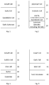
- US2009/0014061 (Harris ) describes a triple junction solar cell as shown in Figure 1 of the present application.
- the structure is an InGaP top subcell, a GaAs middle subcell and a GaInNAsSb bottom subcell, all lattice matched to a GaAs substrate.
- the aim stated by this document is to improve on the efficiency of a record holding InGaP/InGaAs/Ge solar subcell.
- GaInNAsSb For the GaInNAsSb material, it discloses, a bandgap of 0.9 to 1.3 eV and that it can be lattice matched to GaAs, which has a bandgap of 1.42 eV, so a GaInNAsSb subcell can be used to absorb the longer wavelengths passed by the GaAs subcell above it.
- the proposed proportions of In, N and Sb are respectively 0.05 to 0.07, 0.01 to 0.02 and 0.02 to 0.06.
- the document discloses experimental results comparing GaInNAsSb junctions to GaInNAs ones with the former achieving a better internal quantum efficiency and so it claims "The GaInNAsSb material system on substrate [GaAs] ( FIG.
- 1A represents one of the smallest bandgaps ever achieved (0.92eV) in a dilute nitride solar subcell with high carrier collection efficiency.” Further it notes a merit of a 0.92eV bandgap which is that since there is little energy in the solar spectrum between 0.85eV and 0.92eV due to atmospheric absorption, subcells with just smaller bandgaps than that will not provide extra photocurrent.
- US2011/0232730 proposes a lattice matched triple junction solar cell having a similar set of subcells to that of Harris.
- Figure 2 of the present application shows this structure.
- the proposed bottom subcell 21 is GaInNAsSb, but the material is described as "low Sb, enhanced In and N". More specifically the proposed proportions of In, N and Sb are respectively 0.07 to 0.18, 0.025 to 0.04 (higher than Harris) and 0.001 to 0.03 (generally lower than Harris).
- the subcells are lattice matched to the substrate.
- Possibilities of an Al component in the top subcell 23 and of an In component in the middle subcell 22, marked in Figure 2 are disclosed. These enable the materials to be lattice matched to Ge, when that is the substrate. This document also proposes that when the substrate is Ge there may be a fourth subcell in that substrate.
- US2011/0083729 also discloses a triple junction solar cell.
- the structure of Lee is shown in Figure 3 of the present application. Again the top subcell 33 is InGaP, but the middle subcell 32 is GaNAs and the bottom subcell 31 is SiGe.
- the document notes a problem with Ge bottom subcells, which is that because of the small bandgap the current produced by Ge subcells is high compared to GaAs and InGaP top and middle subcells leading to inefficiency.
- the SiGe actually used has a higher bandgap and produces a current that matches that of the InGaP and GaNAs top and middle subcells proposed. In this device the lattice matching is limited.
- the top, middle and bottom subcells are lattice matched to each other at 5.641 ⁇ with the subcells having the following compositions Ga 0.544 In 0.456 P, GaN 0.0092 As 0.9908 , and Si 0.04 Ge 0.96 .
- these subcells are not lattice matched to the substrate 30, which may be of various materials, and a metamorphic buffer layer 34 is employed to reduce the strain. This is produced by changing the composition of the buffer layer while it is grown to change the lattice parameter, which is not only a complex operation but will introduce defects into the structure.
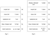
- GB2467934 also owned by the present applicant company, discloses a multijunction solar subcell, shown in Figure 4 of the present application, which has a InGaP top subcell 43, a GaAs middle subcell 2 and a SiGe subcell 41, all lattice matched to a GaAs substrate 40.
- WO2009/157870 discloses an advantageous method for fabricating GaNAsSb, which method, as is explained below, may be used in the preferred examples of the invention.
- the disclosure of this document is incorporated herein by reference.
- EP 1109320 discloses, in one example, multijunction device with a first subcell in a Si 0.17 Ge 0.83 substrate and then with a transition layer to convert the lattice parameter to that of GaAs and a buffer layer overlying that, and then with GaAs and Ga 0.52 In 0.48 P subcells overlying that.
- EP1798777 discloses that SiGe and SiGeSn, amongst various other materials, may be used in the top cell as the low bandgap material in a stack of alternating low bandgap and barrier layers within the depletion region between the emitter and base of the top cell.
- the third layer of the multijunction photovoltaic device may be a light absorbing layer of gallium arsenide material including a photocarrier separating p-n junction.
- the fourth layer of the multijunction photovoltaic device may be a light absorbing layer of indium gallium phosphide including a photocarrier separating p-n junction and being lattice matched to gallium arsenide.
- the multijunction photovoltaic device may further comprise a light absorbing layer of aluminium gallium arsenide including a photocarrier separating p-n junction and being lattice matched to gallium arsenide.
- the multijunction photovoltaic device may further comprise a light absorbing layer of aluminium indium gallium phosphide including a photocarrier separating p-n junction and being lattice matched to gallium arsenide. These additional layers absorb shorter wavelengths than the silicon germanium, or silicon germanium tin, and gallium nitride arsenide antimonide layers.
- the multijunction photovoltaic device may comprise a gallium arsenide substrate, the set of layers being on and lattice matched to the substrate.
- the multijunction photovoltaic device may comprise a substrate that is lattice matched to gallium arsenide, the set of layers being on and lattice matched to the substrate.
- the multijunction photovoltaic device may be a solar cell.
- the present invention also provides a method of making a multijunction photovoltaic device according to claim 9.
- the method may be so performed that the third light absorbing layer is of gallium arsenide material.
- the method may be so performed that the fourth light absorbing layer is of indium gallium phosphide.
- the method may comprise growing a (e.g. fifth) light absorbing layer of aluminium gallium arsenide, including a photocarrier separating p-n junction, lattice matched to gallium arsenide.
- the method may comprise growing a (e.g. fifth) light absorbing layer of aluminium indium gallium phosphide, including a photocarrier separating p-n junction, lattice matched to gallium arsenide.
- a (e.g. fifth) light absorbing layer of aluminium indium gallium phosphide including a photocarrier separating p-n junction, lattice matched to gallium arsenide.
- the method may comprise providing at least one further layer between two neighbouring ones of the said light absorbing layers, the at least one further layer being lattice matched to gallium arsenide.
- the method may comprise removing the substrate.
- the light absorbing layers are arranged in order of bandgap. This may often mean that they are grown in order of bandgap but it would be possible to grow only some of the light absorbing layers, remove the substrate and continue growth in the other direction (a substrate usually being provided on the other side).
- the light absorbing layers with their p-n junctions of the invention may, as is known in the art, each be comprised in a respective region of a multijunction photovoltaic device conventionally known as a subcell, which may have further layers.
- the gallium nitride arsenide antimonide subcell and silicon germanium, or silicon germanium tin, subcell of the invention are able between them to provide good absorption coverage of the spectral wavelengths longer than those absorbed by, for example, a gallium arsenide subcell, offering high absorption efficiency.
- This is in contrast of the approach of US2009/0014061 ( Figure 1 ) and US2011/0232730 ( Figure 2 ) which have only one such subcell, and in those the subcell is of a different and more complex material, namely GaInNAsSb.
- the former document explicitly states that the goal is to have as small a bandgap as possible for the GaInNAsSb.
- this device has no subcell in the 1.4eV region that would be provided by GaAs, and none could be provided simply because it would not lattice match the GaNAs - further, the InGaP subcell in this device would in order to lattice match GaNAs have a larger bandgap (by changing the proportion of In and Ga) than the InGaP subcell used in the examples of the present invention which is lattice matched to GaAs, leaving a large gap in the absorption spectrum of the device of US2011/0083729 .
- subcells both in the invention and as is known generally in the art, may comprise additional layers.
- tunnel contacts may be inserted between the light absorbing subcells of multijunction photovoltaic devices, and these may be so used in the present invention, to provide good electrical connection between the subcells, and to allow the p-n junction in the neighbouring subcells to have the same polarity so that current may flow through the device.
- Window layers and back surface field (BSF) layers are preferably also incorporated into the structure of the device of the invention.
- a window is usually provided at the top of each cell and a back surface field at the bottom of each subcell and these are preferably provided in the invention.
- the invention does provide an advantage in relation to these.
- Figure 5 shows the subcells of first example of a multijunction photovoltaic device, in particular a solar cell, in accordance with the invention.
- This comprises a series of subcells to absorb incident light, formed on a GaAs substrate 50.
- the light is first incident on the subcell 54, which in this example is furthest from the substrate, with light not absorbed by each subcell passing to the next.
- top subcell 54 comprising a light absorbing layer of InGaP material
- an upper middle subcell 53 comprising a light absorbing layer of GaAs 52 and a lower middle subcell comprising a light absorbing layer of GaNAsSb material
- a bottom subcell 51 comprising a light absorbing layer of SiGe material, all of which are lattice matched to a GaAs substrate 50.
- the light absorbing material layer of each of these subcells contains a p-n junction to separate the photocarriers generated.
- the cells are connected in series (tandem cell).
- additional layers which are tunnel contacts (which are provided between the subcells to provide good electrical contact), windows and back surface fields, are incorporated into the structure. These are between the subcells and above and below the light absorbing layers as appropriate. These additional layers are also lattice matched to the GaAs substrate, but as their use is well known in the art and for simplicity of illustration these layers not shown in Figure 5 (similarly for Figure 6 ). Because all the layers are lattice matched, including to the substrate, this reduces the cost of manufacture and enhances device performance, reliability and yield.
- Another advantage of this example is the ability, compared to devices having a Ge substrate with a light absorbing subcell in that, to put a back surface field (BSF) below the p-n junction of SiGe bottom sub-cell for enhanced device performance.
- BSF back surface field
- a sacrificial release layer that has a differential etch rate to GaAs may be grown below the SiGe subcell. This permits the epitaxial layer structure containing the subcells to be removed from the GaAs substrate and transferred to a suitable handle or heat sink, allowing the GaAs substrate to be re-used and if needed reducing the weight of the device. These additional layers are grown epitaxially on the GaAs substrate before the SiGe subcell is grown.
- the subcells may be grown in reverse order on a GaAs substrate (or a substrate lattice matched to GaAs) starting with the widest bandgap subcell (the InGaP subcell in the case of Figure 5 ) and then followed by the narrower bandgap subcells in order (the GaAs subcell, then the GaNAsSb subcell and then the SiGe / SiGeSn subcell in the case of Figure 5 ).
- a sacrificial layer is provided between the widest bandgap subcell and the GaAs substrate allowing the subcells to be removed and transferred to a suitable handle or heat sink, inverted so that the narrowest bandgap cell is next to the handle or heart sink and the widest bandgap cell receives the incident light first.
- the composition of the light absorbing GaNAsSb layer of subcell 52 is such that its bandgap is in the range 0.8 ⁇ E g ⁇ 1.2eV.
- a bandgap of around 1.0 eV is particularly advantageous since it fills the gap between the parts of the spectrum absorbed by the SiGe and GaAs layers.
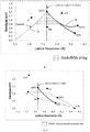
- Figure 7 is a graph showing the bandgap of various Group III-V semiconductor materials and Group IV materials versus their lattice parameter. There are of course numerous III-V materials but the ones shown are selected either to illustrate the GaNAsSb material used in the light absorbing layer of subcell 52 of the invention or for general comparison with well-known materials.
- a solid line 71 extends between the points for GaAs and GaSb giving the values for the ternary compound GaAs 1-y Sb y as the proportion y of Sb atoms varies.
- Dotted line 72 extending from the point for GaAs towards that for GaN, which is off the graph shown at a smaller lattice parameter, giving the values for the ternary compound GaAs 1-x N x as the proportion x of N atoms varies.
- This Figure shows that the substitution of a proportion the As atoms in GaAs by either N or Sb to GaAs reduces the bandgap (even to the range of that of Ge - while it is not practical to add more than a few percent of N that is sufficient to reach the bandgap of Ge).
- substituting in N reduces the lattice parameter
- substituting in Sb increases the lattice parameter. It turns out that substituting in both N and Sb for As, i.e.
- the quaternary material GaN x As 1-x-y Sb y still causes the bandgap to decrease from that of GaAs and with certain proportions of N and Sb the material is lattice matched to GaAs (the effects on lattice parameter of N and Sb cancelling each other out).
- An exact lattice match to GaAs is shown by the vertical dashed line, but strained materials having layer thicknesses below the critical thickness are also possible and lie to either side of the dashed line.
- the shaded area shows possibilities for the quaternary GaNAsSb having bandgaps of the most interest in the invention.
- the region neighbouring the dashed vertical line (which is the lattice matched region) that is within the shaded area also does include bandgaps in the region of 1eV between that of SiGe (around 0.7eV) and GaAs (around 1.4eV).
- N and Sb in the GaNAsSb for a particular bandgap and lattice matching can of course be experimentally determined easily for any particular case. However for lattice matching to GaAs the ratio of N to Sb is about 1:2.6. For bandgaps equal to GaAs (1.4eV) down to 0.9eV the respective proportion of N and Sb, x and y, in the material lie in the range 0 ⁇ x ⁇ 6% and 0 ⁇ y ⁇ 16%.
- a larger bandgap can be obtained for subcell 51 by using SiGeSn instead of SiGe.
- This material is lattice matched to GaAs where the ratio of Si to Sn is approximately 4:1. Where for example the proportion of Si is 2% and that of Sn is 0.5% this provides a larger bandgap than SiGe lattice matched to GaAs, where the proportion of Si is 8% and that of Sn is 2% the bandgap is wider, and where the proportions are much larger the bandgap can extend further.
- Figure 6 shows the subcells of a second example of the invention.
- This device is as that of Figure 5 but it has an additional subcell 55 having a light absorbing layer and a photocarrier separating p-n junction located above the InGaP subcell 54.
- This subcell 55 absorbs part of the spectrum above around 2.0 eV and allows longer wavelengths to be absorbed by the InGaP subcell 54 and the subcells below that.
- the material of the light absorbing layer of this subcell 55 in this example is AlGaAs having a proportion of Al and Ga having the desired bandgap. This material is lattice matched to GaAs, although strained, at all proportions of Al to Ga, and can be grown to thicknesses required for a photovoltaic device to have sufficient absorption without any strain relaxation.
- the light absorbing material layer of subcell 55 is AlInGaP lattice matched to GaAs. Again the bandgap of is preferably about 2.0eV but since the material is a quaternary some extra flexibility is obtained.
- the substrate of the examples is GaAs the invention also extends to cases where the substrate on which the subcells are grown is another material that is lattice matched to GaAs.
- any one or more of subcells 53, 54 or 55 can be omitted.
- the materials of the subcells may be grown using epitaxial techniques including MBE and MOCVD.
- GB2467934 also owned by the present applicant company and mentioned above, discloses examples of SiGe materials manufactured on GaAs substrates. These materials can be grown using an epitaxy process, using a germanium containing precursor (e.g GeH 4 , GeCl 4 , etc.) and a silicon containing precursor (e.g. SiH 4 , SiH 2 Cl 2 , SiHCl 3 , disilane etc.) with a carrier gas (e.g. H 2 ).
- germanium containing precursor e.g GeH 4 , GeCl 4 , etc.
- silicon containing precursor e.g. SiH 4 , SiH 2 Cl 2 , SiHCl 3 , disilane etc.
- carrier gas e.g. H 2
- the p-n junction used to separate the photo carriers may be formed in the SiGe material by various methods. These include doping during the epitaxial growth, or by diffusion in of dopant into a layer of the material when it is grown or is partially grown. An alternative method is given below.
- the SiGe or SiGeSn material used in subcell 51 will in many examples have III-V material directly grown on it. There may then be diffusion of Group V atoms from the III-V material into the SiGe or SiGeSn. Arsenic atoms, for example, will do this. Arsenic in SiGe or SiGeSn is an n-type dopant.
- the Group V atoms diffusing into the SiGe or SiGeSn may well dope the SiGe or SiGeSn forming a p-n junction below the surface of the SiGe or SiGeSn. (If this junction were to be parasitic in a particular example it can be prevented or controlled by forming a thin Si diffusion barrier between the SiGe or SiGeSn. Three atomic layers is sufficient.) However, as foreshadowed, the junction so formed can be utilised as the photocarrier separating junction in the SiGe or SiGeSn subcell.
- the SiGe or SiGeSn subcell may be used as a tunnel diode between the SiGe or SiGeSn subcell and the subcell grown on that.
- a thinner Si barrier can be used to control the amount of diffusion if that is desired.
- the SiGe or SiGeSn neighbouring III-V material grown on it is n-type (i.e. an epitaxially grown SiGe or SiGeSn p-n junction) the diffusion in of Group V atoms will not form an extra p-n junction.
- the GaNAsSb of the invention layer is also formed by epitaxy.
- the p-n junction for separating the photocarriers therein is formed either by doping during the epitaxial growth, or, alternatively, after the layer, or part thereof has been grown and diffusing the dopant in.
- WO2009/157870 described a particularly advantageous method for growing this material.
- the GaAs substrate may be removed when all the subcells have been grown in order on it (which may be in either order). Alternatively the GaAs substrate can be removed at any point during the growth and that may be part way through a subcell including partway through the just one cell. In these methods a new substrate is mounted on the just grown surface.
Description
- The present invention relates to photovoltaic devices having more than one subcell for absorbing different parts of the spectrum of the incident light.
- Multijunction photovoltaic devices comprise a series of subcells each having a light absorbing semiconductor material and a p-n junction therein to separate the photocarriers, to produce the photocurrent. They work by having a top subcell, i.e. that first exposed to the incident light, that has a large bandgap and so absorbs the shorter wavelengths in the incident light only and passes the longer wavelengths, with the next subcell having a smaller bandgap so that it can absorb part of the light passed by the subcell above, and so on. Solar cells are, of course, one kind of photovoltaic device and are ones used to convert sunlight into electricity for the purpose of generating power.
- In this document "top" and "bottom" are to be understood in that sense, i.e. the top subcell is that which receives the incident light first in normal use, rather than the actual spatial orientation of the device. "Above" and "below" are also to be understood similarly, unless the context demands otherwise. Further light is not to be understood as visible light only. For example 1.0 eV and 0.7 eV bandgaps discussed in this document absorb light in the infra-red region.
- Multijunction photovoltaic devices often use lattice matched material, which is to say that when one material is grown on another the lattice parameters of the two materials match to an extent that the crystal structure of the material being grown is maintained and strain relieving dislocations are not introduced. When the lattice parameters of the two materials, in the bulk form, are not quite equal the layer being grown becomes strained, i.e. its lattice parameter changes to match that of the layer on which it grown. Where the strain is quite small the layer being grown can be grown to an arbitrary thickness without the introduction of dislocations. The thickness at which strain relieving dislocations first appear is defined as the critical thickness for a material. In this context, the term lattice matched would also refer to strained layers grown to thicknesses below the critical thickness.
Some examples of known multijunction solar cells are as follows. -
US2009/0014061 (Harris ) describes a triple junction solar cell as shown inFigure 1 of the present application. The structure is an InGaP top subcell, a GaAs middle subcell and a GaInNAsSb bottom subcell, all lattice matched to a GaAs substrate. The aim stated by this document is to improve on the efficiency of a record holding InGaP/InGaAs/Ge solar subcell. For the GaInNAsSb material, it discloses, a bandgap of 0.9 to 1.3 eV and that it can be lattice matched to GaAs, which has a bandgap of 1.42 eV, so a GaInNAsSb subcell can be used to absorb the longer wavelengths passed by the GaAs subcell above it. The proposed proportions of In, N and Sb are respectively 0.05 to 0.07, 0.01 to 0.02 and 0.02 to 0.06. The document discloses experimental results comparing GaInNAsSb junctions to GaInNAs ones with the former achieving a better internal quantum efficiency and so it claims "The GaInNAsSb material system on substrate [GaAs] (FIG. 1A ) represents one of the smallest bandgaps ever achieved (0.92eV) in a dilute nitride solar subcell with high carrier collection efficiency." Further it notes a merit of a 0.92eV bandgap which is that since there is little energy in the solar spectrum between 0.85eV and 0.92eV due to atmospheric absorption, subcells with just smaller bandgaps than that will not provide extra photocurrent. Later it concludes, "Since GaInNAsSb-containing devices produce sufficient current this shows that using this material, rather than Ge, as the bottom junction in a triple-junction GaInP/GaAs/GaInNAsSb device has the potential to increase the power conversion efficiency of triple junction subcells according to the invention by increasing the open-circuit voltage of the devices." -
US2011/0232730 (Jones ) proposes a lattice matched triple junction solar cell having a similar set of subcells to that of Harris.Figure 2 of the present application shows this structure. Again, the proposedbottom subcell 21 is GaInNAsSb, but the material is described as "low Sb, enhanced In and N". More specifically the proposed proportions of In, N and Sb are respectively 0.07 to 0.18, 0.025 to 0.04 (higher than Harris) and 0.001 to 0.03 (generally lower than Harris). The subcells are lattice matched to the substrate. Possibilities of an Al component in thetop subcell 23 and of an In component in themiddle subcell 22, marked inFigure 2 , are disclosed. These enable the materials to be lattice matched to Ge, when that is the substrate. This document also proposes that when the substrate is Ge there may be a fourth subcell in that substrate. -
US2011/0083729 (Lee ) also discloses a triple junction solar cell. The structure of Lee is shown inFigure 3 of the present application. Again thetop subcell 33 is InGaP, but themiddle subcell 32 is GaNAs and thebottom subcell 31 is SiGe. The document notes a problem with Ge bottom subcells, which is that because of the small bandgap the current produced by Ge subcells is high compared to GaAs and InGaP top and middle subcells leading to inefficiency. The SiGe actually used has a higher bandgap and produces a current that matches that of the InGaP and GaNAs top and middle subcells proposed. In this device the lattice matching is limited. In one example, the top, middle and bottom subcells are lattice matched to each other at 5.641 Å with the subcells having the following compositions Ga0.544In0.456P, GaN0.0092As0.9908, and Si0.04Ge0.96. However these subcells are not lattice matched to thesubstrate 30, which may be of various materials, and ametamorphic buffer layer 34 is employed to reduce the strain. This is produced by changing the composition of the buffer layer while it is grown to change the lattice parameter, which is not only a complex operation but will introduce defects into the structure. -
GB2467934 Figure 4 of the present application, which has aInGaP top subcell 43, a GaAs middle subcell 2 and aSiGe subcell 41, all lattice matched to aGaAs substrate 40. -
WO2009/157870 (Yoon ) discloses an advantageous method for fabricating GaNAsSb, which method, as is explained below, may be used in the preferred examples of the invention. The disclosure of this document is incorporated herein by reference. -
EP 1109320 discloses, in one example, multijunction device with a first subcell in a Si0.17Ge0.83 substrate and then with a transition layer to convert the lattice parameter to that of GaAs and a buffer layer overlying that, and then with GaAs and Ga0.52In0.48P subcells overlying that.
EP1798777 discloses that SiGe and SiGeSn, amongst various other materials, may be used in the top cell as the low bandgap material in a stack of alternating low bandgap and barrier layers within the depletion region between the emitter and base of the top cell. - According to the present invention there is provided a multijunction photovoltaic device as specified by claim 1.
- The third layer of the multijunction photovoltaic device may be a light absorbing layer of gallium arsenide material including a photocarrier separating p-n junction.
The fourth layer of the multijunction photovoltaic device may be a light absorbing layer of indium gallium phosphide including a photocarrier separating p-n junction and being lattice matched to gallium arsenide.
The multijunction photovoltaic device may further comprise a light absorbing layer of aluminium gallium arsenide including a photocarrier separating p-n junction and being lattice matched to gallium arsenide.
The multijunction photovoltaic device may further comprise a light absorbing layer of aluminium indium gallium phosphide including a photocarrier separating p-n junction and being lattice matched to gallium arsenide.
These additional layers absorb shorter wavelengths than the silicon germanium, or silicon germanium tin, and gallium nitride arsenide antimonide layers.
The multijunction photovoltaic device may comprise a gallium arsenide substrate, the set of layers being on and lattice matched to the substrate. Alternatively the multijunction photovoltaic device may comprise a substrate that is lattice matched to gallium arsenide, the set of layers being on and lattice matched to the substrate.
The multijunction photovoltaic device may be a solar cell.
The present invention also provides a method of making a multijunction photovoltaic device according to claim 9. - The method may be so performed that the third light absorbing layer is of gallium arsenide material.
- The method may be so performed that the fourth light absorbing layer is of indium gallium phosphide.
- The method may comprise growing a (e.g. fifth) light absorbing layer of aluminium gallium arsenide, including a photocarrier separating p-n junction, lattice matched to gallium arsenide.
- The method may comprise growing a (e.g. fifth) light absorbing layer of aluminium indium gallium phosphide, including a photocarrier separating p-n junction, lattice matched to gallium arsenide.
- The method may comprise providing at least one further layer between two neighbouring ones of the said light absorbing layers, the at least one further layer being lattice matched to gallium arsenide.
- The method may comprise removing the substrate.
- In embodiments of the invention, the light absorbing layers are arranged in order of bandgap. This may often mean that they are grown in order of bandgap but it would be possible to grow only some of the light absorbing layers, remove the substrate and continue growth in the other direction (a substrate usually being provided on the other side).
- The light absorbing layers with their p-n junctions of the invention may, as is known in the art, each be comprised in a respective region of a multijunction photovoltaic device conventionally known as a subcell, which may have further layers.
- The gallium nitride arsenide antimonide subcell and silicon germanium, or silicon germanium tin, subcell of the invention are able between them to provide good absorption coverage of the spectral wavelengths longer than those absorbed by, for example, a gallium arsenide subcell, offering high absorption efficiency. This is in contrast of the approach of
US2009/0014061 (Figure 1 ) andUS2011/0232730 (Figure 2 ) which have only one such subcell, and in those the subcell is of a different and more complex material, namely GaInNAsSb. Further, the former document explicitly states that the goal is to have as small a bandgap as possible for the GaInNAsSb. Also, inUS2011/0083729 (Figure 3 ) there are GaNAs and SiGe layers that absorb in this general area of the spectrum but GaNAs cannot be lattice matched to GaAs which means that in that device a strain relieving buffer layer has to be used between its subcells and the substrate. Further this device has no subcell in the 1.4eV region that would be provided by GaAs, and none could be provided simply because it would not lattice match the GaNAs - further, the InGaP subcell in this device would in order to lattice match GaNAs have a larger bandgap (by changing the proportion of In and Ga) than the InGaP subcell used in the examples of the present invention which is lattice matched to GaAs, leaving a large gap in the absorption spectrum of the device ofUS2011/0083729 . - As noted above, subcells, both in the invention and as is known generally in the art, may comprise additional layers. For example, as is known in the art, tunnel contacts may be inserted between the light absorbing subcells of multijunction photovoltaic devices, and these may be so used in the present invention, to provide good electrical connection between the subcells, and to allow the p-n junction in the neighbouring subcells to have the same polarity so that current may flow through the device. Window layers and back surface field (BSF) layers, as also known in the art, are preferably also incorporated into the structure of the device of the invention. A window is usually provided at the top of each cell and a back surface field at the bottom of each subcell and these are preferably provided in the invention. However, as noted later the invention does provide an advantage in relation to these.
- Examples of the invention will now be described, with reference to the accompanying drawings of which:
- FIGURE 1
- shows the subcells of a first known multijunction solar cell,
- FIGURE 2
- shows the subcells of a second known multijunction solar cell,
- FIGURE 3
- shows the subcells of a third known multijunction solar cell,
- FIGURE 4
- shows the subcells of a fourth known multijunction solar cell,
- FIGURE 5
- shows the subcells of a first example of a multijunction photovoltaic device in accordance with the invention,
- FIGURE 6
- shows the subcells of a second example of a multijunction photovoltaic device in accordance with the invention,
- FIGURE 7
- is a graph showing the bandgap of GaAs and GaNAs of various compositions and the possibilities of bandgap of GaNAsSb when lattice matched to GaAs, and
- Figure 8
- is a graph showing the bandgap and lattice parameter of the alloy SiGeSn, showing that it can be lattice matched to GaAs with a bandgap range of 0.66-∼1.1eV.
-
Figure 5 shows the subcells of first example of a multijunction photovoltaic device, in particular a solar cell, in accordance with the invention. This comprises a series of subcells to absorb incident light, formed on aGaAs substrate 50. The light is first incident on thesubcell 54, which in this example is furthest from the substrate, with light not absorbed by each subcell passing to the next. In this example there are atop subcell 54 comprising a light absorbing layer of InGaP material, anupper middle subcell 53 comprising a light absorbing layer ofGaAs 52 and a lower middle subcell comprising a light absorbing layer of GaNAsSb material and abottom subcell 51 comprising a light absorbing layer of SiGe material, all of which are lattice matched to aGaAs substrate 50. The light absorbing material layer of each of these subcells contains a p-n junction to separate the photocarriers generated. Preferably the cells are connected in series (tandem cell). - In this example, additional layers, which are tunnel contacts (which are provided between the subcells to provide good electrical contact), windows and back surface fields, are incorporated into the structure. These are between the subcells and above and below the light absorbing layers as appropriate. These additional layers are also lattice matched to the GaAs substrate, but as their use is well known in the art and for simplicity of illustration these layers not shown in
Figure 5 (similarly forFigure 6 ). Because all the layers are lattice matched, including to the substrate, this reduces the cost of manufacture and enhances device performance, reliability and yield. Another advantage of this example is the ability, compared to devices having a Ge substrate with a light absorbing subcell in that, to put a back surface field (BSF) below the p-n junction of SiGe bottom sub-cell for enhanced device performance. Additionally, a sacrificial release layer that has a differential etch rate to GaAs may be grown below the SiGe subcell. This permits the epitaxial layer structure containing the subcells to be removed from the GaAs substrate and transferred to a suitable handle or heat sink, allowing the GaAs substrate to be re-used and if needed reducing the weight of the device. These additional layers are grown epitaxially on the GaAs substrate before the SiGe subcell is grown. Alternatively the subcells may be grown in reverse order on a GaAs substrate (or a substrate lattice matched to GaAs) starting with the widest bandgap subcell (the InGaP subcell in the case ofFigure 5 ) and then followed by the narrower bandgap subcells in order (the GaAs subcell, then the GaNAsSb subcell and then the SiGe / SiGeSn subcell in the case ofFigure 5 ). A sacrificial layer is provided between the widest bandgap subcell and the GaAs substrate allowing the subcells to be removed and transferred to a suitable handle or heat sink, inverted so that the narrowest bandgap cell is next to the handle or heart sink and the widest bandgap cell receives the incident light first.
The composition of the light absorbing GaNAsSb layer ofsubcell 52 is such that its bandgap is in the range 0.8 < Eg < 1.2eV. A bandgap of around 1.0 eV is particularly advantageous since it fills the gap between the parts of the spectrum absorbed by the SiGe and GaAs layers. -
Figure 7 is a graph showing the bandgap of various Group III-V semiconductor materials and Group IV materials versus their lattice parameter. There are of course numerous III-V materials but the ones shown are selected either to illustrate the GaNAsSb material used in the light absorbing layer ofsubcell 52 of the invention or for general comparison with well-known materials. In particular asolid line 71 extends between the points for GaAs and GaSb giving the values for the ternary compound GaAs1-ySby as the proportion y of Sb atoms varies.Dotted line 72 extending from the point for GaAs towards that for GaN, which is off the graph shown at a smaller lattice parameter, giving the values for the ternary compound GaAs1-xNx as the proportion x of N atoms varies. This Figure shows that the substitution of a proportion the As atoms in GaAs by either N or Sb to GaAs reduces the bandgap (even to the range of that of Ge - while it is not practical to add more than a few percent of N that is sufficient to reach the bandgap of Ge). However substituting in N reduces the lattice parameter, while substituting in Sb increases the lattice parameter. It turns out that substituting in both N and Sb for As, i.e. to form the quaternary material GaNxAs1-x-ySby, still causes the bandgap to decrease from that of GaAs and with certain proportions of N and Sb the material is lattice matched to GaAs (the effects on lattice parameter of N and Sb cancelling each other out). An exact lattice match to GaAs is shown by the vertical dashed line, but strained materials having layer thicknesses below the critical thickness are also possible and lie to either side of the dashed line. The shaded area shows possibilities for the quaternary GaNAsSb having bandgaps of the most interest in the invention. Note, in particular, that the region neighbouring the dashed vertical line (which is the lattice matched region) that is within the shaded area also does include bandgaps in the region of 1eV between that of SiGe (around 0.7eV) and GaAs (around 1.4eV). - The precise proportions of N and Sb in the GaNAsSb for a particular bandgap and lattice matching can of course be experimentally determined easily for any particular case. However for lattice matching to GaAs the ratio of N to Sb is about 1:2.6. For bandgaps equal to GaAs (1.4eV) down to 0.9eV the respective proportion of N and Sb, x and y, in the material lie in the range 0<x<6% and 0<y<16%.
- To make the SiGe light absorbing layer in
subcell 51 lattice matched to GaAs the proportion of silicon is around 0.018 and this material then has a bandgap of around 0.7eV. As can be seen inFigure 8 , which is another graph showing the bandgap of various Group III-V semiconductor materials and Group IV materials versus their lattice parameter, Ge is not lattice matched to GaAs but as the difference is not large only a small amount of Si needs to be added to achieve the lattice matching. Since SiGe is a binary compound there is only one degree of freedom provided by the proportion of the atoms and so the bandgap is fixed at around 0.7eV if the lattice match to GaAs is to be maintained. - However, if desired a larger bandgap can be obtained for
subcell 51 by using SiGeSn instead of SiGe. This material is lattice matched to GaAs where the ratio of Si to Sn is approximately 4:1. Where for example the proportion of Si is 2% and that of Sn is 0.5% this provides a larger bandgap than SiGe lattice matched to GaAs, where the proportion of Si is 8% and that of Sn is 2% the bandgap is wider, and where the proportions are much larger the bandgap can extend further. -
Figure 6 shows the subcells of a second example of the invention. This device is as that ofFigure 5 but it has anadditional subcell 55 having a light absorbing layer and a photocarrier separating p-n junction located above theInGaP subcell 54. Thissubcell 55 absorbs part of the spectrum above around 2.0 eV and allows longer wavelengths to be absorbed by the InGaP subcell 54 and the subcells below that. The material of the light absorbing layer of thissubcell 55 in this example is AlGaAs having a proportion of Al and Ga having the desired bandgap. This material is lattice matched to GaAs, although strained, at all proportions of Al to Ga, and can be grown to thicknesses required for a photovoltaic device to have sufficient absorption without any strain relaxation. - In another similar example the light absorbing material layer of
subcell 55 is AlInGaP lattice matched to GaAs. Again the bandgap of is preferably about 2.0eV but since the material is a quaternary some extra flexibility is obtained. - The subcells examples of
Figures 5 and 6 described above do not, as is preferred, have further subcells between them. That is however possible with preferably the bandgaps of the light absorbing materials of the intervening subcells being between that of their neighbours. - Note also that while the substrate of the examples is GaAs the invention also extends to cases where the substrate on which the subcells are grown is another material that is lattice matched to GaAs.
- Note further that if not needed for certain applications any one or more of
subcells
The materials of the subcells may be grown using epitaxial techniques including MBE and MOCVD.
For example,GB2467934
The SiGe or SiGeSn material used insubcell 51 will in many examples have III-V material directly grown on it. There may then be diffusion of Group V atoms from the III-V material into the SiGe or SiGeSn. Arsenic atoms, for example, will do this. Arsenic in SiGe or SiGeSn is an n-type dopant.
So if the SiGe or SiGeSn neighbouring the III-V material grown on it is p-type then the Group V atoms diffusing into the SiGe or SiGeSn may well dope the SiGe or SiGeSn forming a p-n junction below the surface of the SiGe or SiGeSn. (If this junction were to be parasitic in a particular example it can be prevented or controlled by forming a thin Si diffusion barrier between the SiGe or SiGeSn. Three atomic layers is sufficient.) However, as foreshadowed, the junction so formed can be utilised as the photocarrier separating junction in the SiGe or SiGeSn subcell. Alternatively it may be used as a tunnel diode between the SiGe or SiGeSn subcell and the subcell grown on that. A thinner Si barrier can be used to control the amount of diffusion if that is desired.
On the other hand if the SiGe or SiGeSn neighbouring III-V material grown on it is n-type (i.e. an epitaxially grown SiGe or SiGeSn p-n junction) the diffusion in of Group V atoms will not form an extra p-n junction.
The GaNAsSb of the invention layer is also formed by epitaxy. The p-n junction for separating the photocarriers therein is formed either by doping during the epitaxial growth, or, alternatively, after the layer, or part thereof has been grown and diffusing the dopant in. The above mentionedWO2009/157870 described a particularly advantageous method for growing this material.
GB2467934 GB2467935
The GaAs substrate may be removed when all the subcells have been grown in order on it (which may be in either order). Alternatively the GaAs substrate can be removed at any point during the growth and that may be part way through a subcell including partway through the just one cell. In these methods a new substrate is mounted on the just grown surface.
Claims (15)
- A multijunction photovoltaic device comprising a set of semiconductor material layers, wherein the layers comprise:a first light absorbing layer (51) of silicon germanium or silicon germanium tin material including a photocarrier separating p-n junction having an associated bandgap energy,a second light absorbing layer (52) including a photocarrier separating p-n junction having an associated bandgap energy, which is between 0.8eV and 1.2eV,a third light absorbing layer (53) including a photocarrier separating p-n junction having an associated bandgap energy, anda fourth light absorbing layer (54) including a photocarrier separating p-n junction having an associated bandgap energy,whereinthe bandgap energy of the first light absorbing layer is lower than the bandgap energy of the second light absorbing layer, which is lower than the bandgap energy of the third light absorbing layer, which is lower than the bandgap energy of the fourth light absorbing layer,the light absorbing layers are arranged in order of bandgap,the second light absorbing layer (52) is of gallium nitride arsenide antimonide material,
andall of the first, second, third, and fourth light absorbing layers (51, 52, 53, 54) are lattice matched to gallium arsenide. - A multijunction photovoltaic device as claimed in a claim 1 wherein the third light absorbing layer (53) is of gallium arsenide material.
- A multijunction photovoltaic device as claimed in claim 1 or claim 2, wherein the fourth light absorbing layer (54) is of indium gallium phosphide.
- A multijunction photovoltaic device as claimed in any preceding claim further comprising a light absorbing layer (55) of aluminium gallium arsenide including a photocarrier separating p-n junction and being lattice matched to gallium arsenide.
- A multijunction photovoltaic device as claimed in any one of claims 1 to 3 further comprising a light absorbing layer (55) of aluminium indium gallium phosphide including a photocarrier separating p-n junction and being lattice matched to gallium arsenide.
- A multijunction photovoltaic device as claimed in any preceding claim comprising a gallium arsenide substrate (50), the set of layers being on and lattice matched to the substrate.
- A multijunction photovoltaic device as claimed in any one of claims 1 to 5 comprising a substrate that is lattice matched to gallium arsenide, the set of layers being on and lattice matched to the substrate.
- A multijunction photovoltaic device as claimed in any preceding claim wherein the photovoltaic device is a solar cell.
- A method of making a multijunction photovoltaic device having at least four layers of material such that there are first, second, third, and fourth light absorbing layers (51, 52, 53, 54) each including a photocarrier separating p-n junction and each having an associated bandgap energy, the bandgap energy of the first light absorbing layer being lower than the bandgap energy of the second light absorbing layer, which is both between 0.8eV and 1.2eV and lower than the bandgap energy of the third light absorbing layer, which is lower than the bandgap energy of the fourth light absorbing layer, the light absorbing layers being arranged in order of bandgap,
and wherein the method comprises:providing a substrate of gallium arsenide (50) or another material that is lattice matched to gallium arsenide,growing the first light absorbing epitaxial layer (51) of silicon germanium or silicon germanium tin material, lattice matched to the substrate,growing the second light absorbing epitaxial layer (52) of gallium nitride arsenide antimonide material, lattice matched to the first light absorbing layer,growing the third light absorbing epitaxial layer, lattice matched to the second light absorbing layer,
andgrowing the fourth light absorbing epitaxial layer, lattice matched to the third light absorbing layer. - A method as claimed in claim 9 wherein the third light absorbing layer (53) is of gallium arsenide material.
- A method as claimed in claim 9 or claim 10 wherein the fourth light absorbing layer (54) is of indium gallium phosphide.
- A method as claimed in any one of claims 9 to 11 comprising growing a light absorbing layer (55) of aluminium gallium arsenide, including a photocarrier separating p-n junction, lattice matched to gallium arsenide.
- A method as claimed in in any one of claims 9 to 11 comprising growing a light absorbing layer (55) of aluminium indium gallium phosphide, including a photocarrier separating p-n junction, lattice matched to gallium arsenide.
- A method as claimed in any of claims 9 to 13 comprising providing at least one further layer between two neighbouring ones of the said light absorbing layers, the at least one further layer being lattice matched to gallium arsenide.
- A method as claimed in any of claims 9 to 14 comprising removing the substrate.
Applications Claiming Priority (2)
| Application Number | Priority Date | Filing Date | Title |
|---|---|---|---|
| US201161528650P | 2011-08-29 | 2011-08-29 | |
| PCT/GB2012/051981 WO2013030530A1 (en) | 2011-08-29 | 2012-08-14 | Photovoltaic device |
Publications (2)
| Publication Number | Publication Date |
|---|---|
| EP2745329A1 EP2745329A1 (en) | 2014-06-25 |
| EP2745329B1 true EP2745329B1 (en) | 2018-09-19 |
Family
ID=46727255
Family Applications (3)
| Application Number | Title | Priority Date | Filing Date |
|---|---|---|---|
| EP12750801.8A Active EP2745329B1 (en) | 2011-08-29 | 2012-08-14 | Photovoltaic device |
| EP12753571.4A Active EP2745330B1 (en) | 2011-08-29 | 2012-08-14 | Photovoltaic device |
| EP12750800.0A Ceased EP2745328A1 (en) | 2011-08-29 | 2012-08-14 | Photovoltaic device |
Family Applications After (2)
| Application Number | Title | Priority Date | Filing Date |
|---|---|---|---|
| EP12753571.4A Active EP2745330B1 (en) | 2011-08-29 | 2012-08-14 | Photovoltaic device |
| EP12750800.0A Ceased EP2745328A1 (en) | 2011-08-29 | 2012-08-14 | Photovoltaic device |
Country Status (7)
| Country | Link |
|---|---|
| US (4) | US10263129B2 (en) |
| EP (3) | EP2745329B1 (en) |
| JP (3) | JP6228119B2 (en) |
| CN (2) | CN103875079B (en) |
| AU (2) | AU2012300694C1 (en) |
| ES (1) | ES2813938T3 (en) |
| WO (3) | WO2013030530A1 (en) |
Families Citing this family (31)
| Publication number | Priority date | Publication date | Assignee | Title |
|---|---|---|---|---|
| US20170141256A1 (en) * | 2009-10-23 | 2017-05-18 | Alta Devices, Inc. | Multi-junction optoelectronic device with group iv semiconductor as a bottom junction |
| US9997659B2 (en) | 2012-09-14 | 2018-06-12 | The Boeing Company | Group-IV solar cell structure using group-IV or III-V heterostructures |
| US11495705B2 (en) | 2012-09-14 | 2022-11-08 | The Boeing Company | Group-IV solar cell structure using group-IV or III-V heterostructures |
| US9099595B2 (en) | 2012-09-14 | 2015-08-04 | The Boeing Company | Group-IV solar cell structure using group-IV or III-V heterostructures |
| US9985160B2 (en) * | 2012-09-14 | 2018-05-29 | The Boeing Company | Group-IV solar cell structure using group-IV or III-V heterostructures |
| US10903383B2 (en) | 2012-09-14 | 2021-01-26 | The Boeing Company | Group-IV solar cell structure using group-IV or III-V heterostructures |
| US11646388B2 (en) | 2012-09-14 | 2023-05-09 | The Boeing Company | Group-IV solar cell structure using group-IV or III-V heterostructures |
| KR20140095738A (en) * | 2013-01-25 | 2014-08-04 | 삼성전자주식회사 | Transistors and methods of manufacturing the same |
| CN103199130B (en) * | 2013-03-15 | 2016-03-09 | 中国科学院苏州纳米技术与纳米仿生研究所 | Formal dress four-junction solar battery and preparation method thereof |
| CN103137766B (en) * | 2013-03-15 | 2015-09-09 | 中国科学院苏州纳米技术与纳米仿生研究所 | Triple-junction monolithic solar cell and preparation method thereof |
| CN103199141A (en) * | 2013-03-15 | 2013-07-10 | 中国科学院苏州纳米技术与纳米仿生研究所 | Four-junction cascading solar battery and preparation method thereof |
| EP2782145A1 (en) * | 2013-03-21 | 2014-09-24 | Alcatel Lucent | Method for manufacturing a multijunction photovoltaic device and resulting multijunction photovoltaic device |
| CN103151414B (en) * | 2013-04-03 | 2016-04-27 | 中国科学院苏州纳米技术与纳米仿生研究所 | Formal dress triple-junction monolithic solar cell and preparation method thereof |
| CN103219412B (en) * | 2013-04-03 | 2016-03-09 | 中国科学院苏州纳米技术与纳米仿生研究所 | Triple-junction monolithic solar cell and preparation method thereof |
| CN103259193B (en) * | 2013-05-14 | 2016-03-09 | 中国科学院苏州纳米技术与纳米仿生研究所 | A kind of 1300nm ~ 1550nm is containing the preparation method of the semiconductor laser of bismuthide |
| CN103311353B (en) * | 2013-05-29 | 2016-09-07 | 中国科学院苏州纳米技术与纳米仿生研究所 | three-junction cascade solar cell and preparation method thereof |
| GB2515322A (en) * | 2013-06-19 | 2014-12-24 | Univ Surrey | Light Receiving Device |
| US20140373906A1 (en) * | 2013-06-25 | 2014-12-25 | Solar Junction Corporation | Anti-reflection coatings for multijunction solar cells |
| CN103426965B (en) * | 2013-08-16 | 2016-12-28 | 中国科学院苏州纳米技术与纳米仿生研究所 | Solaode and preparation method thereof |
| CN104638060B (en) * | 2013-11-13 | 2018-03-06 | 中国电子科技集团公司第十八研究所 | The preparation method of hetero-junctions thermophotovoltaic |
| CN104638046B (en) * | 2013-11-13 | 2017-05-03 | 中国电子科技集团公司第十八研究所 | Heterojunction thermophotovoltaic cell with Ge (germanium) substrate |
| CN103839774A (en) * | 2014-02-25 | 2014-06-04 | 清华大学 | SiGeSn layer and forming method thereof |
| US9548408B2 (en) * | 2014-04-15 | 2017-01-17 | L-3 Communications Cincinnati Electronics Corporation | Tunneling barrier infrared detector devices |
| JP2016082041A (en) * | 2014-10-15 | 2016-05-16 | 株式会社リコー | Compound semiconductor solar cell and manufacturing method of compound semiconductor solar cell |
| EP3408871A1 (en) * | 2016-01-29 | 2018-12-05 | Alta Devices, Inc. | Multi-junction optoelectronic device with group iv semiconductor as a bottom junction |
| CN105720126B (en) * | 2016-04-27 | 2017-07-28 | 天津三安光电有限公司 | A kind of upside-down mounting four-junction solar cell structure and preparation method thereof |
| US20170365732A1 (en) | 2016-06-15 | 2017-12-21 | Solar Junction Corporation | Dilute nitride bismide semiconductor alloys |
| CN106531836A (en) * | 2016-11-25 | 2017-03-22 | 罗雷 | Four-junction solar energy cell |
| CN108807284B (en) * | 2017-04-28 | 2020-06-26 | 环球晶圆股份有限公司 | Epitaxial bonding substrate and manufacturing method thereof |
| US11342498B2 (en) * | 2018-01-08 | 2022-05-24 | Integrated Silicon Solution (cayman) Inc. | High density 3D magnetic random access memory (MRAM) cell integration using wafer cut and transfer |
| CN113066907B (en) * | 2021-06-03 | 2021-08-27 | 南昌凯迅光电有限公司 | Preparation method of three-junction gallium arsenide solar cell with nano-mesh surface electrode |
Family Cites Families (32)
| Publication number | Priority date | Publication date | Assignee | Title |
|---|---|---|---|---|
| WO1987002183A1 (en) * | 1985-09-30 | 1987-04-09 | Kanegafuchi Kagaku Kogyo Kabushiki Kaisha | Multijunction semiconductor device |
| JPS6437060A (en) * | 1987-08-03 | 1989-02-07 | Nippon Telegraph & Telephone | Semiconductor element |
| US6281426B1 (en) * | 1997-10-01 | 2001-08-28 | Midwest Research Institute | Multi-junction, monolithic solar cell using low-band-gap materials lattice matched to GaAs or Ge |
| US5944913A (en) * | 1997-11-26 | 1999-08-31 | Sandia Corporation | High-efficiency solar cell and method for fabrication |
| US6380601B1 (en) * | 1999-03-29 | 2002-04-30 | Hughes Electronics Corporation | Multilayer semiconductor structure with phosphide-passivated germanium substrate |
| JP3657143B2 (en) * | 1999-04-27 | 2005-06-08 | シャープ株式会社 | Solar cell and manufacturing method thereof |
| US6252287B1 (en) * | 1999-05-19 | 2001-06-26 | Sandia Corporation | InGaAsN/GaAs heterojunction for multi-junction solar cells |
| US6340788B1 (en) * | 1999-12-02 | 2002-01-22 | Hughes Electronics Corporation | Multijunction photovoltaic cells and panels using a silicon or silicon-germanium active substrate cell for space and terrestrial applications |
| US7339109B2 (en) | 2000-06-20 | 2008-03-04 | Emcore Corporation | Apparatus and method for optimizing the efficiency of germanium junctions in multi-junction solar cells |
| JP2002222989A (en) * | 2001-01-26 | 2002-08-09 | Toshiba Corp | Semiconductor light-emitting device |
| US6815736B2 (en) | 2001-02-09 | 2004-11-09 | Midwest Research Institute | Isoelectronic co-doping |
| US20030015728A1 (en) * | 2001-07-17 | 2003-01-23 | Motorola, Inc. | Photonic biasing and integrated solar charging networks for integrated circuits |
| US20060162768A1 (en) * | 2002-05-21 | 2006-07-27 | Wanlass Mark W | Low bandgap, monolithic, multi-bandgap, optoelectronic devices |
| US7126052B2 (en) * | 2002-10-02 | 2006-10-24 | The Boeing Company | Isoelectronic surfactant induced sublattice disordering in optoelectronic devices |
| CA2551123A1 (en) * | 2004-01-20 | 2005-07-28 | Cyrium Technologies Incorporated | Solar cell with epitaxially grown quantum dot material |
| US10069026B2 (en) | 2005-12-19 | 2018-09-04 | The Boeing Company | Reduced band gap absorber for solar cells |
| US7872252B2 (en) * | 2006-08-11 | 2011-01-18 | Cyrium Technologies Incorporated | Method of fabricating semiconductor devices on a group IV substrate with controlled interface properties and diffusion tails |
| US20080257405A1 (en) * | 2007-04-18 | 2008-10-23 | Emcore Corp. | Multijunction solar cell with strained-balanced quantum well middle cell |
| US20090014061A1 (en) | 2007-07-10 | 2009-01-15 | The Board Of Trustees Of The Leland Stanford Junior University | GaInNAsSb solar cells grown by molecular beam epitaxy |
| WO2009157870A1 (en) | 2008-06-26 | 2009-12-30 | Nanyang Technological University | Method for fabricating ganassb semiconductor |
| CN101431117A (en) * | 2008-11-24 | 2009-05-13 | 北京索拉安吉清洁能源科技有限公司 | Multi-junction solar cell with doping blocking layer |
| US20100147366A1 (en) * | 2008-12-17 | 2010-06-17 | Emcore Solar Power, Inc. | Inverted Metamorphic Multijunction Solar Cells with Distributed Bragg Reflector |
| GB2467935B (en) | 2009-02-19 | 2013-10-30 | Iqe Silicon Compounds Ltd | Formation of thin layers of GaAs and germanium materials |
| GB2467934B (en) | 2009-02-19 | 2013-10-30 | Iqe Silicon Compounds Ltd | Photovoltaic cell |
| WO2010102345A1 (en) * | 2009-03-12 | 2010-09-16 | Shaun Joseph Cunningham | Improved photo-voltaic device and system |
| US20100282305A1 (en) * | 2009-05-08 | 2010-11-11 | Emcore Solar Power, Inc. | Inverted Multijunction Solar Cells with Group IV/III-V Hybrid Alloys |
| US20100282307A1 (en) * | 2009-05-08 | 2010-11-11 | Emcore Solar Power, Inc. | Multijunction Solar Cells with Group IV/III-V Hybrid Alloys for Terrestrial Applications |
| US20100282306A1 (en) * | 2009-05-08 | 2010-11-11 | Emcore Solar Power, Inc. | Multijunction Solar Cells with Group IV/III-V Hybrid Alloys |
| TW201114043A (en) | 2009-10-02 | 2011-04-16 | Epistar Corp | A high efficiency solar cell |
| US20110232730A1 (en) | 2010-03-29 | 2011-09-29 | Solar Junction Corp. | Lattice matchable alloy for solar cells |
| US9214580B2 (en) | 2010-10-28 | 2015-12-15 | Solar Junction Corporation | Multi-junction solar cell with dilute nitride sub-cell having graded doping |
| WO2013074530A2 (en) * | 2011-11-15 | 2013-05-23 | Solar Junction Corporation | High efficiency multijunction solar cells |
-
2012
- 2012-08-14 JP JP2014527730A patent/JP6228119B2/en active Active
- 2012-08-14 AU AU2012300694A patent/AU2012300694C1/en not_active Ceased
- 2012-08-14 CN CN201280049676.9A patent/CN103875079B/en active Active
- 2012-08-14 EP EP12750801.8A patent/EP2745329B1/en active Active
- 2012-08-14 US US14/342,061 patent/US10263129B2/en active Active
- 2012-08-14 US US14/241,987 patent/US20150041863A1/en not_active Abandoned
- 2012-08-14 WO PCT/GB2012/051981 patent/WO2013030530A1/en active Application Filing
- 2012-08-14 CN CN201711071248.7A patent/CN107845690B/en not_active Expired - Fee Related
- 2012-08-14 ES ES12753571T patent/ES2813938T3/en active Active
- 2012-08-14 EP EP12753571.4A patent/EP2745330B1/en active Active
- 2012-08-14 EP EP12750800.0A patent/EP2745328A1/en not_active Ceased
- 2012-08-14 WO PCT/GB2012/051982 patent/WO2013030531A1/en active Application Filing
- 2012-08-14 WO PCT/GB2012/051980 patent/WO2013030529A1/en active Application Filing
- 2012-08-14 US US14/342,016 patent/US20140345679A1/en not_active Abandoned
-
2016
- 2016-01-19 AU AU2016200282A patent/AU2016200282B2/en not_active Ceased
- 2016-12-16 US US15/382,181 patent/US10367107B2/en active Active
-
2017
- 2017-10-12 JP JP2017198245A patent/JP2018026580A/en active Pending
-
2019
- 2019-07-26 JP JP2019137470A patent/JP2019216249A/en active Pending
Non-Patent Citations (1)
| Title |
|---|
| None * |
Also Published As
| Publication number | Publication date |
|---|---|
| US20140326301A1 (en) | 2014-11-06 |
| AU2012300694B2 (en) | 2015-10-22 |
| CN107845690B (en) | 2020-09-08 |
| US10367107B2 (en) | 2019-07-30 |
| AU2012300694C1 (en) | 2016-04-21 |
| WO2013030531A1 (en) | 2013-03-07 |
| US10263129B2 (en) | 2019-04-16 |
| AU2016200282B2 (en) | 2017-08-31 |
| AU2012300694A8 (en) | 2014-04-03 |
| EP2745329A1 (en) | 2014-06-25 |
| WO2013030529A1 (en) | 2013-03-07 |
| JP6228119B2 (en) | 2017-11-08 |
| US20150041863A1 (en) | 2015-02-12 |
| EP2745330B1 (en) | 2020-06-03 |
| JP2018026580A (en) | 2018-02-15 |
| JP2014527725A (en) | 2014-10-16 |
| CN103875079B (en) | 2017-12-12 |
| EP2745330A1 (en) | 2014-06-25 |
| JP2019216249A (en) | 2019-12-19 |
| AU2012300694A1 (en) | 2014-03-20 |
| WO2013030530A1 (en) | 2013-03-07 |
| ES2813938T3 (en) | 2021-03-25 |
| EP2745328A1 (en) | 2014-06-25 |
| AU2016200282A1 (en) | 2016-02-11 |
| CN103875079A (en) | 2014-06-18 |
| US20140345679A1 (en) | 2014-11-27 |
| CN107845690A (en) | 2018-03-27 |
| US20170117429A1 (en) | 2017-04-27 |
Similar Documents
| Publication | Publication Date | Title |
|---|---|---|
| EP2745329B1 (en) | Photovoltaic device | |
| US20210104641A1 (en) | GROUP-IV SOLAR CELL STRUCTURE USING GROUP-IV or III-V HETEROSTRUCTURES | |
| US11133429B2 (en) | Group-IV solar cell structure using group-IV or III-V heterostructures | |
| TWI600173B (en) | Multijunction solar cell with low band gap absorbing layer in the middle cell and method for fabricating the same | |
| US11646388B2 (en) | Group-IV solar cell structure using group-IV or III-V heterostructures | |
| US10896990B2 (en) | Group-IV solar cell structure using group-IV or III-V heterostructures | |
| US11495705B2 (en) | Group-IV solar cell structure using group-IV or III-V heterostructures | |
| US20090272438A1 (en) | Strain Balanced Multiple Quantum Well Subcell In Inverted Metamorphic Multijunction Solar Cell | |
| US20140196774A1 (en) | Multi-junction iii-v solar cell | |
| EP2573825B1 (en) | Multi-layer back surface field layer in a solar cell structure | |
| US10903383B2 (en) | Group-IV solar cell structure using group-IV or III-V heterostructures |
Legal Events
| Date | Code | Title | Description |
|---|---|---|---|
| PUAI | Public reference made under article 153(3) epc to a published international application that has entered the european phase |
Free format text: ORIGINAL CODE: 0009012 |
|
| 17P | Request for examination filed |
Effective date: 20140321 |
|
| AK | Designated contracting states |
Kind code of ref document: A1 Designated state(s): AL AT BE BG CH CY CZ DE DK EE ES FI FR GB GR HR HU IE IS IT LI LT LU LV MC MK MT NL NO PL PT RO RS SE SI SK SM TR |
|
| DAX | Request for extension of the european patent (deleted) | ||
| 17Q | First examination report despatched |
Effective date: 20160620 |
|
| STAA | Information on the status of an ep patent application or granted ep patent |
Free format text: STATUS: EXAMINATION IS IN PROGRESS |
|
| GRAP | Despatch of communication of intention to grant a patent |
Free format text: ORIGINAL CODE: EPIDOSNIGR1 |
|
| STAA | Information on the status of an ep patent application or granted ep patent |
Free format text: STATUS: GRANT OF PATENT IS INTENDED |
|
| INTG | Intention to grant announced |
Effective date: 20170628 |
|
| GRAJ | Information related to disapproval of communication of intention to grant by the applicant or resumption of examination proceedings by the epo deleted |
Free format text: ORIGINAL CODE: EPIDOSDIGR1 |
|
| STAA | Information on the status of an ep patent application or granted ep patent |
Free format text: STATUS: EXAMINATION IS IN PROGRESS |
|
| INTC | Intention to grant announced (deleted) | ||
| GRAS | Grant fee paid |
Free format text: ORIGINAL CODE: EPIDOSNIGR3 |
|
| STAA | Information on the status of an ep patent application or granted ep patent |
Free format text: STATUS: GRANT OF PATENT IS INTENDED |
|
| GRAP | Despatch of communication of intention to grant a patent |
Free format text: ORIGINAL CODE: EPIDOSNIGR1 |
|
| INTG | Intention to grant announced |
Effective date: 20180312 |
|
| GRAJ | Information related to disapproval of communication of intention to grant by the applicant or resumption of examination proceedings by the epo deleted |
Free format text: ORIGINAL CODE: EPIDOSDIGR1 |
|
| GRAL | Information related to payment of fee for publishing/printing deleted |
Free format text: ORIGINAL CODE: EPIDOSDIGR3 |
|
| STAA | Information on the status of an ep patent application or granted ep patent |
Free format text: STATUS: EXAMINATION IS IN PROGRESS |
|
| GRAR | Information related to intention to grant a patent recorded |
Free format text: ORIGINAL CODE: EPIDOSNIGR71 |
|
| STAA | Information on the status of an ep patent application or granted ep patent |
Free format text: STATUS: GRANT OF PATENT IS INTENDED |
|
| GRAA | (expected) grant |
Free format text: ORIGINAL CODE: 0009210 |
|
| STAA | Information on the status of an ep patent application or granted ep patent |
Free format text: STATUS: THE PATENT HAS BEEN GRANTED |
|
| INTG | Intention to grant announced |
Effective date: 20180726 |
|
| RIN1 | Information on inventor provided before grant (corrected) |
Inventor name: JOHNSON, DR ANDREW |
|
| AK | Designated contracting states |
Kind code of ref document: B1 Designated state(s): AL AT BE BG CH CY CZ DE DK EE ES FI FR GB GR HR HU IE IS IT LI LT LU LV MC MK MT NL NO PL PT RO RS SE SI SK SM TR |
|
| REG | Reference to a national code |
Ref country code: GB Ref legal event code: FG4D |
|
| REG | Reference to a national code |
Ref country code: CH Ref legal event code: EP |
|
| REG | Reference to a national code |
Ref country code: AT Ref legal event code: REF Ref document number: 1044241 Country of ref document: AT Kind code of ref document: T Effective date: 20181015 |
|
| REG | Reference to a national code |
Ref country code: IE Ref legal event code: FG4D |
|
| REG | Reference to a national code |
Ref country code: DE Ref legal event code: R096 Ref document number: 602012051288 Country of ref document: DE |
|
| REG | Reference to a national code |
Ref country code: CH Ref legal event code: NV Representative=s name: SCHMAUDER AND PARTNER AG PATENT- UND MARKENANW, CH |
|
| REG | Reference to a national code |
Ref country code: NL Ref legal event code: MP Effective date: 20180919 |
|
| PG25 | Lapsed in a contracting state [announced via postgrant information from national office to epo] |
Ref country code: LT Free format text: LAPSE BECAUSE OF FAILURE TO SUBMIT A TRANSLATION OF THE DESCRIPTION OR TO PAY THE FEE WITHIN THE PRESCRIBED TIME-LIMIT Effective date: 20180919 Ref country code: RS Free format text: LAPSE BECAUSE OF FAILURE TO SUBMIT A TRANSLATION OF THE DESCRIPTION OR TO PAY THE FEE WITHIN THE PRESCRIBED TIME-LIMIT Effective date: 20180919 Ref country code: FI Free format text: LAPSE BECAUSE OF FAILURE TO SUBMIT A TRANSLATION OF THE DESCRIPTION OR TO PAY THE FEE WITHIN THE PRESCRIBED TIME-LIMIT Effective date: 20180919 Ref country code: GR Free format text: LAPSE BECAUSE OF FAILURE TO SUBMIT A TRANSLATION OF THE DESCRIPTION OR TO PAY THE FEE WITHIN THE PRESCRIBED TIME-LIMIT Effective date: 20181220 Ref country code: BG Free format text: LAPSE BECAUSE OF FAILURE TO SUBMIT A TRANSLATION OF THE DESCRIPTION OR TO PAY THE FEE WITHIN THE PRESCRIBED TIME-LIMIT Effective date: 20181219 Ref country code: NO Free format text: LAPSE BECAUSE OF FAILURE TO SUBMIT A TRANSLATION OF THE DESCRIPTION OR TO PAY THE FEE WITHIN THE PRESCRIBED TIME-LIMIT Effective date: 20181219 Ref country code: SE Free format text: LAPSE BECAUSE OF FAILURE TO SUBMIT A TRANSLATION OF THE DESCRIPTION OR TO PAY THE FEE WITHIN THE PRESCRIBED TIME-LIMIT Effective date: 20180919 |
|
| REG | Reference to a national code |
Ref country code: LT Ref legal event code: MG4D |
|
| PG25 | Lapsed in a contracting state [announced via postgrant information from national office to epo] |
Ref country code: HR Free format text: LAPSE BECAUSE OF FAILURE TO SUBMIT A TRANSLATION OF THE DESCRIPTION OR TO PAY THE FEE WITHIN THE PRESCRIBED TIME-LIMIT Effective date: 20180919 Ref country code: AL Free format text: LAPSE BECAUSE OF FAILURE TO SUBMIT A TRANSLATION OF THE DESCRIPTION OR TO PAY THE FEE WITHIN THE PRESCRIBED TIME-LIMIT Effective date: 20180919 Ref country code: LV Free format text: LAPSE BECAUSE OF FAILURE TO SUBMIT A TRANSLATION OF THE DESCRIPTION OR TO PAY THE FEE WITHIN THE PRESCRIBED TIME-LIMIT Effective date: 20180919 |
|
| REG | Reference to a national code |
Ref country code: AT Ref legal event code: MK05 Ref document number: 1044241 Country of ref document: AT Kind code of ref document: T Effective date: 20180919 |
|
| PG25 | Lapsed in a contracting state [announced via postgrant information from national office to epo] |
Ref country code: CZ Free format text: LAPSE BECAUSE OF FAILURE TO SUBMIT A TRANSLATION OF THE DESCRIPTION OR TO PAY THE FEE WITHIN THE PRESCRIBED TIME-LIMIT Effective date: 20180919 Ref country code: AT Free format text: LAPSE BECAUSE OF FAILURE TO SUBMIT A TRANSLATION OF THE DESCRIPTION OR TO PAY THE FEE WITHIN THE PRESCRIBED TIME-LIMIT Effective date: 20180919 Ref country code: EE Free format text: LAPSE BECAUSE OF FAILURE TO SUBMIT A TRANSLATION OF THE DESCRIPTION OR TO PAY THE FEE WITHIN THE PRESCRIBED TIME-LIMIT Effective date: 20180919 Ref country code: IS Free format text: LAPSE BECAUSE OF FAILURE TO SUBMIT A TRANSLATION OF THE DESCRIPTION OR TO PAY THE FEE WITHIN THE PRESCRIBED TIME-LIMIT Effective date: 20190119 Ref country code: PL Free format text: LAPSE BECAUSE OF FAILURE TO SUBMIT A TRANSLATION OF THE DESCRIPTION OR TO PAY THE FEE WITHIN THE PRESCRIBED TIME-LIMIT Effective date: 20180919 Ref country code: ES Free format text: LAPSE BECAUSE OF FAILURE TO SUBMIT A TRANSLATION OF THE DESCRIPTION OR TO PAY THE FEE WITHIN THE PRESCRIBED TIME-LIMIT Effective date: 20180919 Ref country code: NL Free format text: LAPSE BECAUSE OF FAILURE TO SUBMIT A TRANSLATION OF THE DESCRIPTION OR TO PAY THE FEE WITHIN THE PRESCRIBED TIME-LIMIT Effective date: 20180919 Ref country code: RO Free format text: LAPSE BECAUSE OF FAILURE TO SUBMIT A TRANSLATION OF THE DESCRIPTION OR TO PAY THE FEE WITHIN THE PRESCRIBED TIME-LIMIT Effective date: 20180919 |
|
| PG25 | Lapsed in a contracting state [announced via postgrant information from national office to epo] |
Ref country code: PT Free format text: LAPSE BECAUSE OF FAILURE TO SUBMIT A TRANSLATION OF THE DESCRIPTION OR TO PAY THE FEE WITHIN THE PRESCRIBED TIME-LIMIT Effective date: 20190119 Ref country code: SM Free format text: LAPSE BECAUSE OF FAILURE TO SUBMIT A TRANSLATION OF THE DESCRIPTION OR TO PAY THE FEE WITHIN THE PRESCRIBED TIME-LIMIT Effective date: 20180919 Ref country code: SK Free format text: LAPSE BECAUSE OF FAILURE TO SUBMIT A TRANSLATION OF THE DESCRIPTION OR TO PAY THE FEE WITHIN THE PRESCRIBED TIME-LIMIT Effective date: 20180919 |
|
| REG | Reference to a national code |
Ref country code: DE Ref legal event code: R097 Ref document number: 602012051288 Country of ref document: DE |
|
| PLBE | No opposition filed within time limit |
Free format text: ORIGINAL CODE: 0009261 |
|
| STAA | Information on the status of an ep patent application or granted ep patent |
Free format text: STATUS: NO OPPOSITION FILED WITHIN TIME LIMIT |
|
| PG25 | Lapsed in a contracting state [announced via postgrant information from national office to epo] |
Ref country code: DK Free format text: LAPSE BECAUSE OF FAILURE TO SUBMIT A TRANSLATION OF THE DESCRIPTION OR TO PAY THE FEE WITHIN THE PRESCRIBED TIME-LIMIT Effective date: 20180919 |
|
| 26N | No opposition filed |
Effective date: 20190620 |
|
| PGFP | Annual fee paid to national office [announced via postgrant information from national office to epo] |
Ref country code: BE Payment date: 20190617 Year of fee payment: 8 |
|
| PG25 | Lapsed in a contracting state [announced via postgrant information from national office to epo] |
Ref country code: SI Free format text: LAPSE BECAUSE OF FAILURE TO SUBMIT A TRANSLATION OF THE DESCRIPTION OR TO PAY THE FEE WITHIN THE PRESCRIBED TIME-LIMIT Effective date: 20180919 |
|
| PGFP | Annual fee paid to national office [announced via postgrant information from national office to epo] |
Ref country code: IE Payment date: 20190813 Year of fee payment: 8 |
|
| PGFP | Annual fee paid to national office [announced via postgrant information from national office to epo] |
Ref country code: CH Payment date: 20190819 Year of fee payment: 8 |
|
| PG25 | Lapsed in a contracting state [announced via postgrant information from national office to epo] |
Ref country code: TR Free format text: LAPSE BECAUSE OF FAILURE TO SUBMIT A TRANSLATION OF THE DESCRIPTION OR TO PAY THE FEE WITHIN THE PRESCRIBED TIME-LIMIT Effective date: 20180919 |
|
| PG25 | Lapsed in a contracting state [announced via postgrant information from national office to epo] |
Ref country code: LU Free format text: LAPSE BECAUSE OF NON-PAYMENT OF DUE FEES Effective date: 20190814 Ref country code: MC Free format text: LAPSE BECAUSE OF FAILURE TO SUBMIT A TRANSLATION OF THE DESCRIPTION OR TO PAY THE FEE WITHIN THE PRESCRIBED TIME-LIMIT Effective date: 20180919 |
|
| REG | Reference to a national code |
Ref country code: CH Ref legal event code: PL |
|
| GBPC | Gb: european patent ceased through non-payment of renewal fee |
Effective date: 20200814 |
|
| PG25 | Lapsed in a contracting state [announced via postgrant information from national office to epo] |
Ref country code: CH Free format text: LAPSE BECAUSE OF NON-PAYMENT OF DUE FEES Effective date: 20200831 Ref country code: LI Free format text: LAPSE BECAUSE OF NON-PAYMENT OF DUE FEES Effective date: 20200831 |
|
| REG | Reference to a national code |
Ref country code: BE Ref legal event code: MM Effective date: 20200831 |
|
| PG25 | Lapsed in a contracting state [announced via postgrant information from national office to epo] |
Ref country code: CY Free format text: LAPSE BECAUSE OF FAILURE TO SUBMIT A TRANSLATION OF THE DESCRIPTION OR TO PAY THE FEE WITHIN THE PRESCRIBED TIME-LIMIT Effective date: 20180919 |
|
| REG | Reference to a national code |
Ref country code: GB Ref legal event code: S28 Free format text: APPLICATION FILED |
|
| REG | Reference to a national code |
Ref country code: GB Ref legal event code: S28 Free format text: RESTORATION ALLOWED Effective date: 20210616 |
|
| PG25 | Lapsed in a contracting state [announced via postgrant information from national office to epo] |
Ref country code: HU Free format text: LAPSE BECAUSE OF FAILURE TO SUBMIT A TRANSLATION OF THE DESCRIPTION OR TO PAY THE FEE WITHIN THE PRESCRIBED TIME-LIMIT; INVALID AB INITIO Effective date: 20120814 Ref country code: MT Free format text: LAPSE BECAUSE OF FAILURE TO SUBMIT A TRANSLATION OF THE DESCRIPTION OR TO PAY THE FEE WITHIN THE PRESCRIBED TIME-LIMIT Effective date: 20180919 |
|
| PG25 | Lapsed in a contracting state [announced via postgrant information from national office to epo] |
Ref country code: IE Free format text: LAPSE BECAUSE OF NON-PAYMENT OF DUE FEES Effective date: 20200814 Ref country code: GB Free format text: LAPSE BECAUSE OF NON-PAYMENT OF DUE FEES Effective date: 20200814 Ref country code: BE Free format text: LAPSE BECAUSE OF NON-PAYMENT OF DUE FEES Effective date: 20200831 |
|
| PGFP | Annual fee paid to national office [announced via postgrant information from national office to epo] |
Ref country code: FR Payment date: 20210714 Year of fee payment: 10 |
|
| PG25 | Lapsed in a contracting state [announced via postgrant information from national office to epo] |
Ref country code: MK Free format text: LAPSE BECAUSE OF FAILURE TO SUBMIT A TRANSLATION OF THE DESCRIPTION OR TO PAY THE FEE WITHIN THE PRESCRIBED TIME-LIMIT Effective date: 20180919 |
|
| PG25 | Lapsed in a contracting state [announced via postgrant information from national office to epo] |
Ref country code: FR Free format text: LAPSE BECAUSE OF NON-PAYMENT OF DUE FEES Effective date: 20220831 |
|
| PGFP | Annual fee paid to national office [announced via postgrant information from national office to epo] |
Ref country code: IT Payment date: 20230822 Year of fee payment: 12 Ref country code: GB Payment date: 20230828 Year of fee payment: 12 |
|
| PGFP | Annual fee paid to national office [announced via postgrant information from national office to epo] |
Ref country code: DE Payment date: 20230829 Year of fee payment: 12 |