EP2743216A1 - Dispositif d'accumulation de produits - Google Patents
Dispositif d'accumulation de produits Download PDFInfo
- Publication number
- EP2743216A1 EP2743216A1 EP20140157924 EP14157924A EP2743216A1 EP 2743216 A1 EP2743216 A1 EP 2743216A1 EP 20140157924 EP20140157924 EP 20140157924 EP 14157924 A EP14157924 A EP 14157924A EP 2743216 A1 EP2743216 A1 EP 2743216A1
- Authority
- EP
- European Patent Office
- Prior art keywords
- conveyor belt
- conveyor
- belt
- products
- workstation
- Prior art date
- Legal status (The legal status is an assumption and is not a legal conclusion. Google has not performed a legal analysis and makes no representation as to the accuracy of the status listed.)
- Granted
Links
Images

Classifications
-
- B—PERFORMING OPERATIONS; TRANSPORTING
- B65—CONVEYING; PACKING; STORING; HANDLING THIN OR FILAMENTARY MATERIAL
- B65G—TRANSPORT OR STORAGE DEVICES, e.g. CONVEYORS FOR LOADING OR TIPPING, SHOP CONVEYOR SYSTEMS OR PNEUMATIC TUBE CONVEYORS
- B65G47/00—Article or material-handling devices associated with conveyors; Methods employing such devices
- B65G47/22—Devices influencing the relative position or the attitude of articles during transit by conveyors
- B65G47/26—Devices influencing the relative position or the attitude of articles during transit by conveyors arranging the articles, e.g. varying spacing between individual articles
- B65G47/261—Accumulating articles
- B65G47/268—Accumulating articles by means of belt or chain conveyor
-
- B—PERFORMING OPERATIONS; TRANSPORTING
- B65—CONVEYING; PACKING; STORING; HANDLING THIN OR FILAMENTARY MATERIAL
- B65G—TRANSPORT OR STORAGE DEVICES, e.g. CONVEYORS FOR LOADING OR TIPPING, SHOP CONVEYOR SYSTEMS OR PNEUMATIC TUBE CONVEYORS
- B65G47/00—Article or material-handling devices associated with conveyors; Methods employing such devices
- B65G47/34—Devices for discharging articles or materials from conveyor
- B65G47/46—Devices for discharging articles or materials from conveyor and distributing, e.g. automatically, to desired points
- B65G47/51—Devices for discharging articles or materials from conveyor and distributing, e.g. automatically, to desired points according to unprogrammed signals, e.g. influenced by supply situation at destination
- B65G47/5104—Devices for discharging articles or materials from conveyor and distributing, e.g. automatically, to desired points according to unprogrammed signals, e.g. influenced by supply situation at destination for articles
- B65G47/5109—Devices for discharging articles or materials from conveyor and distributing, e.g. automatically, to desired points according to unprogrammed signals, e.g. influenced by supply situation at destination for articles first In - First Out systems: FIFO
- B65G47/5113—Devices for discharging articles or materials from conveyor and distributing, e.g. automatically, to desired points according to unprogrammed signals, e.g. influenced by supply situation at destination for articles first In - First Out systems: FIFO using endless conveyors
- B65G47/5118—Devices for discharging articles or materials from conveyor and distributing, e.g. automatically, to desired points according to unprogrammed signals, e.g. influenced by supply situation at destination for articles first In - First Out systems: FIFO using endless conveyors with variable accumulation capacity
- B65G47/5131—Devices for discharging articles or materials from conveyor and distributing, e.g. automatically, to desired points according to unprogrammed signals, e.g. influenced by supply situation at destination for articles first In - First Out systems: FIFO using endless conveyors with variable accumulation capacity by relative displacement between conveyors or conveyor parts and bridging means therebetween
-
- B—PERFORMING OPERATIONS; TRANSPORTING
- B65—CONVEYING; PACKING; STORING; HANDLING THIN OR FILAMENTARY MATERIAL
- B65G—TRANSPORT OR STORAGE DEVICES, e.g. CONVEYORS FOR LOADING OR TIPPING, SHOP CONVEYOR SYSTEMS OR PNEUMATIC TUBE CONVEYORS
- B65G21/00—Supporting or protective framework or housings for endless load-carriers or traction elements of belt or chain conveyors
- B65G21/10—Supporting or protective framework or housings for endless load-carriers or traction elements of belt or chain conveyors movable, or having interchangeable or relatively movable parts; Devices for moving framework or parts thereof
- B65G21/14—Supporting or protective framework or housings for endless load-carriers or traction elements of belt or chain conveyors movable, or having interchangeable or relatively movable parts; Devices for moving framework or parts thereof to allow adjustment of length or configuration of load-carrier or traction element
-
- B—PERFORMING OPERATIONS; TRANSPORTING
- B65—CONVEYING; PACKING; STORING; HANDLING THIN OR FILAMENTARY MATERIAL
- B65G—TRANSPORT OR STORAGE DEVICES, e.g. CONVEYORS FOR LOADING OR TIPPING, SHOP CONVEYOR SYSTEMS OR PNEUMATIC TUBE CONVEYORS
- B65G2201/00—Indexing codes relating to handling devices, e.g. conveyors, characterised by the type of product or load being conveyed or handled
- B65G2201/02—Articles
- B65G2201/0235—Containers
- B65G2201/0244—Bottles
Definitions
- the present invention relates to a product accumulation device for conveying said products from a first workstation to a second workstation by constituting a buffer zone making it possible in particular to compensate for the differences in work rates between the first workstation and the workstation. work and the second workstation and thus, to regulate the production line.
- the invention also relates to an installation which comprises at least a first workstation and a second workstation, and an accumulation device, object of the invention, arranged between said workstations.
- Such an accumulation device is already known to those skilled in the art.
- This is for example described in the document FR 2,524,436 and comprises a first linear conveyor belt configured to transfer articles in a first direction, a second linear conveyor belt, parallel to the first conveyor belt, configured to transfer the articles in a second inverted direction relative to the first and a third conveyor belt forming a semicircle, configured to transfer the articles of the first conveyor belt to the second conveyor belt.
- the accumulation device also comprises translation means configured to translate the third conveyor belt relative to the first and second conveyor belts, in the first direction or vice versa in the second direction. This third conveyor belt is shifted upwards with respect to the first and second conveyor belts.
- two ramps are arranged at the two ends of the third conveyor belt and secured thereto so that the translation of the third conveyor belt concomitantly allows the movement of the ramps that slide with respect to the first and second mats conveyors for modulating the length of the accumulation device.
- These ramps allow on the one hand the rise of products from the first conveyor to the third conveyor belt and vice versa the descent products of the third conveyor belt to the second conveyor belt.
- These ramps consist of a tongue on which the products slide during their rise or descent, under the effect of the thrust exerted by the products arranged upstream and moving in the direction of conveyance on the conveyor belts.
- the ramps slide on the first and second belt conveyors during their movement, concomitantly with the third conveyor belt, which can cause premature degradation of said first and second conveyor belts.
- the design of the accumulation device according to this document FR 2,524,436 is particularly suitable for products whose mass is low such as biscuits. It is understood that if the mass of the products is much larger such as for example for bottles, such a ramp design can cause difficulties in transferring the products of the first conveyor belt to the third conveyor belt and conversely of the third conveyor belt to the conveyor belt.
- second conveyor belt since said transfer is effected by sliding on the tongues and therefore requires a greater thrust of the products arranged upstream, which may possibly slide on the first conveyor belt or tilt.
- the products may have difficulty crossing the edge of said tongue, which may possibly cause the products to tilt.
- the document JP 59 053315 also describes an accumulation device, which comprises a ramp system associated with a semicircular roller conveyor gravity type having a downward slope whose input is raised relative to the output.
- the conveyed objects are brought up through the ramp system from a first belt and then descend by gravity to the second belt by traversing the semicircular roller conveyor from its entrance to its exit located under the first conveyor. end.
- Such a device does not allow to convey series of products to remain well aligned with each other.
- the object of the invention is to implement an accumulation device to overcome the aforementioned drawbacks.
- the invention relates to an accumulation device according to claim 1.
- the slopes are made directly on the first conveyor belt and the second conveyor belt, which facilitates the transport of items since the transfer takes place directly between the carpets which are in motion and eliminates the passage by an intermediate step on a ramp according to which said products are transferred by sliding under the effect of the thrust of the articles arranged upstream.
- This design according to the invention is therefore also well suited for products with low mass and large mass.
- the transfer being performed directly between the conveyor belts this limits the risk of tipping products.
- both the inlet and the outlet of the third conveyor belt are raised relative to the first and second conveyor belts.
- the first and second conveyor belts are linear, the second conveyor belt being parallel to the first conveyor belt.
- the third conveyor belt forms a semicircle.
- the first conveyor belt comprises a first conveyor belt which is provided with a first internal face
- the second conveyor belt comprises a second conveyor belt which is provided with a second internal face
- the first and second ramp systems respectively comprise first and second rollers which are pivotally mounted along axes transverse to the first and second second conveyor belts and adjoining the first and second ends of the third conveyor belt, these first and second rollers bearing respectively on the first and second inner faces to form said first and second slopes.
- first and second ends of the third conveyor belt are raised relative to the first and second conveyor belts with the two ramps.
- the third conveyor belt comprises a third conveyor belt which is motorized.
- the accumulation device comprises a motor, preferably fixed to a housing of the third conveyor belt, for moving the third conveyor belt.
- the third conveyor belt is configured so that the forward speed of the third conveyor belt is synchronized with the forward speed of the first and second conveyor belts. An interest is to be able to precisely regulate the rate of advance of the products on the production line.
- the conveyor belt extends in a plane, preferably substantially horizontal.
- the first conveyor belt is provided with a first outer face and the second conveyor belt is provided with a second outer face.
- first and second ramp systems comprise first and second counter-rollers which are pivotally mounted along transverse axes to the first and second conveyor belts and configured to bear respectively against the first and second outer faces, so as to restore the normal position of the first and second conveyor belts.
- against-rollers reduces the friction of these on the outer faces of the conveyor belts.
- the first system of ramps comprises two first flanges positioned in the extension of the first end of the third conveyor belt to which they are subject. These first two flanges are positioned with a spacing between them, each on one of the lateral sides of the first conveyor belt.
- the first roller and the first counter-roller are mounted in pivot connection along the transverse axes, relative to the first two flanges.
- the second system of ramps comprises two second flanges positioned in the extension of the second end of the third conveyor belt to which they are subject.
- the two second flanges are positioned with a spacing between them, each on one of the lateral sides of the second conveyor belt.
- the second roller and the second roller against are mounted pivotally connected along the transverse axes, with respect to the two second flanges.
- the accumulation device comprises a fixed support structure on which are mounted the first and second conveyor belts and a movable carrying structure on which are mounted the third conveyor belt and the first and second conveyor systems. ramps.
- a slide connection is arranged between the fixed bearing structure and the movable bearing structure for moving the third belt and the two ramp systems in the first or second direction with respect to the first and second conveyor belts.
- the accumulation device object of the invention comprises a transmission system arranged between the fixed carrier structure and the mobile carrier structure and a motor configured to actuate the transmission system.
- This transmission system is preferably of the rack / pinion type. However, we can consider other embodiments such as a belt or an endless screw.
- the invention also relates to an installation comprising a first workstation, a second workstation and an accumulation device according to the invention, said accumulation device being arranged between the first workstation and the second workstation. work to move products from the first workstation to the second workstation.
- the installation object of the invention is configured for the packaging of the products, the first workstation comprising a shrinkwrapper configured to bundle together several products and the second workstation comprising a palletizer configured to package on pallets product packages.
- the installation according to the invention is configured for packaging bottles-type products.
- it can be considered for use for any other type of product such as for example biscuits, or pharmaceuticals.
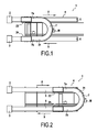
- the installation 1 illustrated in FIG. Figures 1 and 2 is configured for packaging bottles of boxes or other products, the latter including a first workstation 2 comprising a bundling machine configured to bundle by means of a film, the bottles together, for example to form bundles of four , six or even eight bottles, the storage device according to the invention then to route the packets of bottles to a second workstation 3 which, in this case, consists of a palletizer for packaging packages of bottles on bottles pallets.
- a first workstation 2 comprising a bundling machine configured to bundle by means of a film, the bottles together, for example to form bundles of four , six or even eight bottles
- the storage device according to the invention then to route the packets of bottles to a second workstation 3 which, in this case, consists of a palletizer for packaging packages of bottles on bottles pallets.
- a second workstation 3 which, in this case, consists of a palletizer for packaging packages of bottles on bottles pallets.
- the accumulation device 4 comprises a first conveyor belt 5, a second conveyor belt 6 and a third conveyor belt 7.
- the first conveyor belt 5 and the second conveyor belt 6 are linear.
- These conveyor belts 5 and 6 are preferably constituted by a conveyor belt mounted in a loop and rotating on itself by means of a motor-type drive system known to those skilled in the art.
- the conveyor belts comprise a hinged modular chain, preferably made of plastic.
- the first conveyor belt 5 allows the delivery of the products at the output of the first workstation 2, in a first direction defined by the arrow 8 illustrated in FIGS. Figures 1 and 2 .
- the second conveyor belt 6 enables the products to be conveyed in a second direction defined by the arrow 9 illustrated on the Figures 1 and 2 , so as to route the articles to the second workstation 3.
- the third conveyor belt comprises a semicircular shape as illustrated on the Figures 1 and 2 , which allows to transfer the products of the first carpet Conveyor 5 to the second conveyor belt 6. It is also noted that these first and second conveyor belts 5 and 6 are arranged linearly and are parallel to each other.
- the accumulation device further comprises a motor M connected to the conveyor belt 31 of the third conveyor belt 7 for advancing said conveyor belt along a semi-circular path.
- the conveyor belt 31 is mounted in a loop by means of rollers arranged in the casing of the third conveyor belt.
- the conveyor belt 31 of the third conveyor belt 7 extends in a horizontal plane. More exactly, it is understood that it is the outer face of said conveyor belt 31 of the third conveyor belt which extends in a horizontal plane.
- the advancement of the conveyor belt of the third conveyor belt makes it possible to bring the products to be conveyed from the entrance to the exit of the third conveyor belt, the products moving in a horizontal plane.
- the accumulation device 4 comprises a first fixed carrier structure 10 and a second movable carrier structure 11 with respect to the fixed carrier structure 10.
- the movable bearing structure 11 is mounted in sliding connection with respect to the fixed supporting structure 10.
- the fixed supporting structure 10 comprises guide rails 12, 13 while the movable carrying structure 11 comprises rollers 14, 15, 16 , 17, 18, 19 distributed uniformly on said movable carrier structure 11.
- This slide connection makes it possible to translate the movable bearing structure 11 relative to the fixed bearing structure 10 either in the direction of the arrow 8 or vice versa of the arrow 9, in so as to minimize the product accumulation zone or on the contrary to increase as much as possible said accumulation zone, as can be see respectively on Figures 1 and 2 .
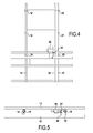
- a motor 20 which allows the driving in rotation of a pinion 21 engraining with a rack 22 arranged in the direction of the length parallel to the rails 12, 13, as illustrated on the Figures 4 and 5 .
- the motor 20 is in two directions of rotation, making it possible to cause the pinion 21 to rotate in a first direction of rotation or in a second direction of rotation and thus to move the movable carrier structure 11 in the direction of the arrow 8 or conversely in the direction of the arrow 9. It could of course be envisaged other transmission systems operated by means of a motor such as for example a worm or a transmission belt.
- the first ramp system 23 is arranged between the first conveyor belt 5 and the third conveyor belt 7 and makes it possible to mount products from the first conveyor belt 5 to the third conveyor belt 7 on which accumulate the products.
- the second ramp system 24 is arranged between the third conveyor belt 7 and the second conveyor belt 6 and allows the products of the third conveyor belt 7 to descend to the second conveyor belt 6.
- the horizontal plane in which the conveyor belt of the third conveyor belt 31 extends is situated above the first and second conveyor belts. These are the first and second ramp systems that allow the products to go up and down.
- the ramp systems 23, 24 are implemented by deforming the conveyor belt 25 of the first conveyor belt 5 and the conveyor belt 26 of the second conveyor belt 6. It can be seen that the first and the second conveyor belts 25, 26 each comprise an inner face 25a, 26a and an outer face 25b, 26b.
- the ramp systems 23, 24 each comprise a first flange 23a, 24a and a second flange 23b, 24b as illustrated on the figure 3 .
- the inner flange 23b of the first ramp system is fixed to the inner flange 24a of the second ramp system to stiffen the assembly.
- these ramp systems 23, 24 each comprise a backing roll 28, illustrated in FIG. figure 6 , which is supported on the outer face 25b, 26b of the conveyor belt 25, 26 of the first and second conveyor belt 5, 6.
- This against-roller 28, which is preferably arranged under the third conveyor belt, allows to restore the position normal of the conveyor belt 25, 26 in the plane P of said first and second conveyor belts 5, 6.
- Figures 3 and 6 that the roller 27 and the counter-roller 28 are pivotally mounted along transverse axes 29, 30 with respect to the conveyor belts 25, 26 of the first and second conveyor belts 5, 6.
- roller 27 is disposed between the lower end of the ramp system and the counter roller 28, the roller 27 being positioned higher than the counter roller 28. This configuration minimizes the torsional forces applied to the conveyor belts the passage of the rollers and against-rollers.
- the flanges 23a, 23b are fixed on the movable bearing structure 11, at the first end 7a of the third conveyor belt 7, and positioned on each lateral side of the conveyor belt 25 of the first conveyor belt 5 as shown in FIG. figure 3 .
- the flanges 24a, 24b of the second ramp system 24 are fixed on said carrier structure 11, at the second end 7b of the third conveyor belt 7, and positioned on each lateral side of the conveyor belt 26 of the second conveyor belt 6. It is thus clear that these ramp systems 23, 24 are subject to both ends 7a, 7b of the third conveyor belt 7.
- rollers 27 are positioned adjacent to the conveyor belt 31 of the third conveyor belt 7 so as to ensure the transfer in a rising movement of the products of the conveyor belt 25 of the first conveyor belt 5 onto the conveyor belt 31 of the conveyor belt third conveyor belt 7, and conversely the transfer in a downward movement of the products of the conveyor belt 31 of the third conveyor belt 7 on the conveyor belt 26 of the second conveyor belt 6.
- the counter-roller 28 makes it possible to restore the position of the conveyor belt 5, 6 of the first and second rollers 5, 6 by avoiding a contact of the said band with the conveyor belt 31 of the third conveyor belt 7, as can be seen on FIG. figure 6 .
Abstract
Description
- La présente invention concerne un dispositif d'accumulation de produits permettant l'acheminement desdits produits d'un premier poste de travail vers un second poste de travail en constituant une zone tampon permettant notamment de compenser les différences de cadences de travail entre le premier poste de travail et le second poste de travail et ainsi, de réguler la ligne de production. L'invention concerne également une installation qui comprend au moins un premier poste de travail et un second poste de travail, ainsi qu'un dispositif d'accumulation, objet de l'invention, agencé entre lesdits postes de travail.
- Un tel dispositif d'accumulation est déjà connu de l'homme du métier. Celui-ci est par exemple décrit dans le document
FR 2 524 436 FR 2 524 436 - Le document
JP 59 053315 - L'objet de l'invention est de mettre en oeuvre un dispositif d'accumulation permettant de pallier les inconvénients précités. Pour cela, l'invention porte sur un dispositif d'accumulation selon la revendication 1.
- On comprend que selon cette conception du dispositif d'accumulation objet de l'invention, les pentes sont réalisées directement sur le premier tapis convoyeur et le second tapis convoyeur, ce qui facilite l'acheminement des articles puisque le transfert s'effectue directement entre les tapis qui sont en mouvement et supprime le passage par une étape intermédiaire sur une rampe selon laquelle lesdits produits sont transférés par glissement sous l'effet de la poussée des articles disposés en amont. Cette conception selon l'invention est donc aussi bien adaptée pour les produits de masse faible que de masse importante. En outre, le transfert étant réalisé directement entre les tapis convoyeurs, cela limite les risques de basculement des produits.
- On comprend également que tant l'entrée que la sortie du troisième tapis convoyeur sont surélevées par rapport aux premier et second tapis convoyeurs.
- Avantageusement, les premier et second tapis convoyeurs sont linéaires, le second tapis convoyeur étant parallèle au premier tapis convoyeur.
- Avantageusement, le troisième tapis convoyeur forme un demi-cercle.
- Selon le dispositif d'accumulation objet de l'invention, le premier tapis convoyeur comprend une première bande transporteuse qui est munie d'une première face interne, le second tapis convoyeur comprend une seconde bande transporteuse qui est munie d'une seconde face interne. En outre, les premier et second systèmes de rampes comprennent respectivement un premier et second rouleaux qui sont montés à pivotement selon des axes transversaux aux première et seconde bandes transporteuses et de manière attenante aux première et seconde extrémités du troisième tapis convoyeur, ces premier et second rouleaux prenant appui respectivement sur les première et seconde faces internes pour constituer lesdites première et seconde pentes. L'utilisation de tels rouleaux supprime les frottements sur la face interne des bandes transporteuses, lors des déplacements des première et second systèmes de rampes concomitamment au troisième tapis convoyeur.
- On comprend donc que les première et seconde extrémités du troisième tapis convoyeur sont surélevées par rapport aux premier et second tapis convoyeurs grâce aux deux rampes.
- De préférence, le troisième tapis convoyeur comporte une troisième bande transporteuse qui est motorisée. A cet effet, le dispositif d'accumulation comporte un moteur, de préférence fixé à un carter du troisième tapis convoyeur, permettant de mettre en mouvement la troisième bande transporteuse. De préférence, le troisième tapis convoyeur est configuré pour que la vitesse d'avancée de la troisième bande transporteuse soit synchronisée avec la vitesse d'avancée des première et seconde bandes transporteuses. Un intérêt est de pouvoir réguler précisément la vitesse d'avancée des produits sur la ligne de fabrication.
- Par ailleurs, la bande transporteuse s'étend dans un plan, de préférence, sensiblement horizontal.
- Selon le dispositif d'accumulation objet de l'invention, la première bande transporteuse est munie d'une première face externe et la seconde bande transporteuse est munie d'une seconde face externe.
- En outre, les premier et second systèmes de rampes comprennent un premier et second contre-rouleaux qui sont montés à pivotement selon des axes transversaux aux première et seconde bandes transporteuses et configurés pour prendre appui respectivement contre les première et seconde faces externe, en sorte de rétablir la position normale des première et seconde bandes transporteuses. De même, l'utilisation de contre-rouleaux réduit les frottements de ceux-ci sur les faces externes des bandes transporteuses.
- Selon le dispositif d'accumulation objet de l'invention, le premier système de rampes comprend deux premiers flasques positionnés dans le prolongement de la première extrémité du troisième tapis convoyeur à laquelle ils sont assujettis. Ces deux premiers flasques sont positionnés avec un écartement entre eux, chacun sur un des côtés latéraux de la première bande transporteuse. En outre, le premier rouleau et le premier contre-rouleau sont montés en liaison pivot selon les axes transversaux, par rapport aux deux premiers flasques.
- De même, selon le dispositif d'accumulation objet de l'invention, le second système de rampes comprend deux seconds flasques positionnés dans le prolongement de la seconde extrémité du troisième tapis convoyeur à laquelle ils sont assujettis. Les deux seconds flasques sont positionnés avec un écartement entre eux, chacun sur un des côtés latéraux de la seconde bande transporteuse. En outre, le second rouleau et le second contre-rouleau sont montés en liaison pivot selon les axes transversaux, par rapport aux deux seconds flasques.
- Selon le dispositif d'accumulation objet de l'invention, celui-ci comprend une structure porteuse fixe sur laquelle sont montés les premier et second tapis convoyeurs et une structure porteuse mobile sur laquelle sont montés le troisième tapis convoyeur et les premier et second systèmes de rampes. En outre, une liaison glissière est agencée entre la structure porteuse fixe et la structure porteuse mobile pour déplacer le troisième tapis et les deux systèmes de rampes, dans le premier ou le second sens par rapport aux premier et second tapis convoyeurs.
- Selon le dispositif d'accumulation objet de l'invention, celui-ci comprend un système de transmission agencé entre la structure porteuse fixe et la structure porteuse mobile et un moteur configuré pour actionner le système de transmission. Ce système de transmission est de préférence du type pignon/crémaillère. On peut toutefois envisager d'autres modes de mise en oeuvre tels qu'une courroie ou une vis sans fin.
- L'invention porte également sur une installation comprenant un premier poste de travail, un second poste de travail et un dispositif d'accumulation objet de l'invention, ledit dispositif d'accumulation étant agencé entre le premier poste de travail et le second poste de travail pour acheminer des produits du premier poste de travail vers le second poste de travail.
- Selon l'installation objet de l'invention, celle-ci est configurée pour le conditionnement des produits, le premier poste de travail comprenant une fardeleuse configurée pour empaqueter ensemble plusieurs produits et le second poste de travail comprenant un palettiseur configuré pour conditionner sur des palettes les paquets de produits.
- De manière préférentielle, l'installation selon l'invention est configurée pour le conditionnement des produits de type bouteilles. On peut toutefois envisager son utilisation pour tout autre type de produit tel que par exemple des biscuits, ou bien des produits pharmaceutiques.
- Les caractéristiques de la présente invention apparaîtront à la lecture de la description suivante d'un mode préférentiel de conception s'appuyant sur des figures parmi lesquelles :
- les
figures 1 et 2 illustrent une vue de dessus d'une installation comprenant un dispositif d'accumulation agencé entre un premier poste de travail et un second poste de travail, dans une première position d'accumulation minimum et dans une seconde position où l'accumulation est maximum ; - la
figure 3 illustre une vue en perspective du dispositif d'accumulation objet de l'invention ; - les
figures 4 et 5 illustrent une vue de dessus et une vue de face de la structure du support des tapis convoyeurs ; - la
figure 6 illustre une vue de côté mettant en évidence la conception du système de rampes. - Selon un mode préférentiel de réalisation, l'installation 1 illustrée en
figures 1 et 2 est configurée pour le conditionnement de bouteilles de boîtes ou de tout autre produit, celle-ci comprenant un premier poste de travail 2 comprenant une fardeleuse configurée pour empaqueter au moyen d'un film, les bouteilles ensemble, par exemple pour constituer des paquets de quatre, six voire huit bouteilles, le dispositif d'accumulation selon l'invention permettant ensuite d'acheminer les paquets de bouteilles vers un second poste de travail 3 qui, dans ce cas, consiste en un palettiseur permettant le conditionnement des paquets de bouteilles sur des palettes. On peut bien entendu envisager la mise en oeuvre d'autres installations équipées d'un tel dispositif d'accumulation objet de l'invention, pour d'autres applications et d'autres produits ou articles, dès l'instant où il est nécessaire de pouvoir moduler la quantité de produits accumulés entre le premier poste de travail 2 et le second poste de travail 3, en fonction de la cadence de travail desdits postes. - On constate en regard des
figures 1 et 2 que le dispositif d'accumulation 4 comprend un premier tapis convoyeur 5, un second tapis convoyeur 6 et un troisième tapis convoyeur 7. Le premier tapis convoyeur 5 et le second tapis convoyeur 6 sont linéaires. Ces tapis convoyeurs 5 et 6 sont de préférence constitués d'une bande transporteuse montée en boucle et tournant sur elle-même au moyen d'un système d'entraînement de type moteur, connu de l'homme du métier. Dans cet exemple non limitatif, les bandes transporteuses comportent une chaîne modulaire à charnières, de préférence en plastique. - Le premier tapis convoyeur 5 permet l'acheminement des produits en sortie du premier poste de travail 2, dans un premier sens défini par la flèche 8 illustrée sur les
figures 1 et 2 . Inversement, le second tapis convoyeur 6 permet l'acheminement des produits dans un second sens défini par la flèche 9 illustrée sur lesfigures 1 et 2 , en sorte d'acheminer les articles vers le second poste de travail 3. En outre, le troisième tapis convoyeur comprend une forme semi-circulaire telle qu'illustrée sur lesfigures 1 et 2 , ce qui permet de transférer les produits du premier tapis convoyeur 5 vers le second tapis convoyeur 6. On constate par ailleurs que ces premier et second tapis convoyeurs 5 et 6 sont disposés linéairement et sont parallèles entre eux. - Le dispositif d'accumulation selon l'invention comporte en outre un moteur M relié à la bande transporteuse 31 du troisième tapis convoyeur 7 permettant de faire avancer ladite bande transporteuse selon une trajectoire semi-circulaire. Pour ce faire, la bande transporteuse 31 est montée en boucle à l'aide de rouleaux disposés dans le carter du troisième tapis convoyeur.
- Par ailleurs, comme on le constate sur les
figures 1, 2 ,3 et 6 , la bande transporteuse 31 du troisième tapis convoyeur 7 s'étend dans un plan horizontal. Plus exactement, on comprend que c'est la face externe de ladite bande transporteuse 31 du troisième tapis convoyeur qui s'étend dans un plan horizontal. - L'avancement de la bande transporteuse du troisième tapis convoyeur permet d'amener les produits à convoyer depuis l'entrée vers la sortie du troisième tapis convoyeur, les produits se déplaçant dans un plan horizontal.
- Tel qu'on le constate sur la
figure 3 , le dispositif d'accumulation 4 comprend une première structure porteuse fixe 10 et une seconde structure porteuse mobile 11 par rapport à la structure porteuse fixe 10. Pour cela, tel qu'on le constate sur lesfigures 4 et 5 , la structure porteuse mobile 11 est montée en liaison glissière par rapport à la structure porteuse fixe 10. La structure porteuse fixe 10 comprend des rails de guidage 12, 13 tandis que la structure porteuse mobile 11 comprend des galets de roulement 14, 15, 16, 17, 18, 19 répartis uniformément sur ladite structure porteuse mobile 11. Cette liaison glissière permet de translater la structure porteuse mobile 11 par rapport à la structure porteuse fixe 10 soit dans le sens de la flèche 8 ou inversement de la flèche 9, en sorte de réduire au maximum la zone d'accumulation de produits ou au contraire d'augmenter au maximum ladite zone d'accumulation, tel qu'on peut le constater respectivement sur lesfigures 1 et 2 . - On constate également la présence d'un moteur 20 qui permet l'entraînement en rotation d'un pignon 21 engrainant avec une crémaillère 22 disposée dans le sens de la longueur parallèlement aux rails 12, 13, tel qu'illustré sur les
figures 4 et 5 . Le moteur 20 est à double sens de rotation, permettant d'entraîner la rotation du pignon 21 dans un premier sens de rotation ou dans un second sens de rotation et ainsi, de déplacer la structure porteuse mobile 11 dans le sens de la flèche 8 ou inversement dans le sens de la flèche 9. On pourrait bien entendu envisager d'autres systèmes de transmission actionnés au moyen d'un moteur tel que par exemple une vis sans fin ou une courroie de transmission. - On constate au regard de la
figure 3 la présence de deux systèmes de rampes 23, 24. Le premier système de rampe 23 est agencé entre le premier tapis convoyeur 5 et le troisième tapis convoyeur 7 et permet de monter des produits du premier tapis convoyeur 5 vers le troisième tapis convoyeur 7 sur lequel s'accumulent les produits. Inversement, le second système de rampes 24 est agencé entre le troisième tapis convoyeur 7 et le second tapis convoyeur 6 et permet la descente des produits du troisième tapis convoyeur 7 vers le second tapis convoyeur 6. - On comprend donc que le plan horizontal dans lequel s'étend la bande transporteuse du troisième tapis convoyeur 31 est situé au-dessus des premier et second tapis convoyeurs. Ce sont donc les premier et second systèmes de rampes qui permettent de faire monter et descendre les produits.
- On constate en regard des
figures 3 et 6 que les systèmes de rampes 23, 24 sont mis en oeuvre en réalisant une déformation de la bande transporteuse 25 du premier tapis convoyeur 5 et de la bande transporteuse 26 du second tapis convoyeur 6. On constate que la première et la seconde bandes transporteuses 25, 26 comprennent chacune une face interne 25a, 26a et une face externe 25b, 26b. Les systèmes de rampes 23, 24 comprennent chacun un premier flasque 23a, 24a et un second flasque 23b, 24b tel qu'illustré sur lafigure 3 . Le flasque interne 23b du premier système de rampe est fixé au flasque interne 24a du second système de rampe afin de rigidifier l'ensemble. - On constate en regard de la
figure 6 que ces systèmes de rampes 23, 24, comprennent chacun un premier rouleau 27 lequel prend appui contre la face interne 25a, 26a de la bande transporteuse 25, 26 des premier et second tapis convoyeurs 5, 6, en sorte de constituer une pente telle qu'illustrée sur lesfigures 3 et 6 permettant de compenser la différence de hauteur entre le premier tapis convoyeur 5 et le troisième tapis convoyeur 7 et de même, entre le second tapis convoyeur 6 et le troisième tapis convoyeur 7. - En outre, ces systèmes de rampes 23, 24, comprennent chacun un contre-rouleau 28, illustré en
figure 6 , lequel prend appui sur la face externe 25b, 26b de la bande transporteuse 25, 26 du premier et second tapis convoyeurs 5, 6. Ce contre-rouleau 28, qui est de préférence disposé sous le troisième tapis convoyeur, permet de rétablir la position normale de la bande transporteuse 25, 26 dans le plan P desdits premier et second tapis convoyeurs 5, 6. On constate en regard desfigures 3 et 6 que le rouleau 27 et le contre-rouleau 28 sont montés à pivotement selon des axes transversaux 29, 30 par rapport aux bandes transporteuses 25, 26 du premier et du second tapis convoyeurs 5, 6. - De plus, le rouleau 27 est disposé entre l'extrémité basse du système de rampe et le contre rouleau 28, le rouleau 27 étant positionné plus haut que le contre rouleau 28. Cette configuration permet de minimiser les efforts de torsion appliqués sur les bandes transporteuses au passage des rouleaux et contre-rouleaux.
- Les flasques 23a, 23b sont fixées sur la structure porteuse mobile 11, au niveau de la première extrémité 7a du troisième tapis convoyeur 7, et positionnées de chaque côté latéral de la bande transporteuse 25 du premier tapis convoyeur 5 tel qu'illustré sur la
figure 3 . De même, les flasques 24a, 24b du second système de rampes 24 sont fixées sur ladite structure porteuse 11, au niveau de la seconde extrémité 7b du troisième tapis convoyeur 7, et positionnées de chaque côté latéral de la bande transporteuse 26 du second tapis convoyeur 6. On comprend donc que ces systèmes de rampes 23, 24 sont assujettis aux deux extrémités 7a, 7b du troisième tapis convoyeur 7. Ainsi, la translation du troisième tapis convoyeur 7 dans le sens de la flèche 8 ou inversement de la flèche 9 permet concomitamment le déplacement des rouleaux 27 et contre-rouleaux 28, assurant un déplacement des pentes sur les bandes transporteuses 25, 26 des premier et second tapis convoyeurs 5, 6. - On constate au regard des
figures 3 et4 que les rouleaux 27 sont positionnés de manière attenante à la bande transporteuse 31 du troisième tapis convoyeur 7 en sorte d'assurer convenablement le transfert dans un mouvement de montée des produits de la bande transporteuse 25 du premier tapis convoyeur 5 sur la bande transporteuse 31 du troisième tapis convoyeur 7, et inversement le transfert dans un mouvement de descente des produits de la bande transporteuse 31 du troisième tapis convoyeur 7 sur la bande transporteuse 26 du second tapis convoyeur 6. - Le contre-rouleau 28 permet de rétablir la position de la bande transporteuse 5, 6 des premier et second rouleaux 5, 6 en évitant un contact de ladite bande avec la bande transporteuse 31 du troisième tapis convoyeur 7, comme on peut le constater sur la
figure 6 . - D'autres caractéristiques peuvent être envisagées sans sortir du cadre de la présente invention, notamment quant à la conception des tapis convoyeurs 5 et 6, aux postes de travail 2 et 3, à la transmission entre la structure mobile 11 et la structure fixe 10.
Claims (12)
- Dispositif d'accumulation (4) comprenant un premier tapis convoyeur (5) configuré pour transférer des articles dans un premier sens (8), un second tapis convoyeur (6) configuré pour transférer les articles dans un second sens (9) inversé au premier sens, un troisième tapis convoyeur (7) configuré pour transférer les articles du premier tapis convoyeur (5) vers le second tapis convoyeur (6) et, des moyens de translation (10 , 11) configurés pour déplacer le troisième tapis convoyeur (7) par rapport aux premier et second tapis convoyeurs (5, 6), dans le premier sens (8) ou dans le second sens (9), ledit troisième tapis convoyeur étant décalé vers le haut par rapport aux premier et second tapis convoyeur, caractérisé en ce que le dispositif d'accumulation (4) comprend deux systèmes de rampe (23, 24) assujettis respectivement aux deux extrémités (7a, 7b) du troisième tapis (7), le premier système de rampe (23) étant configuré pour déformer le premier tapis convoyeur (5) et constituer une première pente assurant la montée des articles du premier tapis convoyeur (5) sur le troisième tapis convoyeur (7) et, le second système de rampe (24) étant configuré pour déformer le second tapis convoyeur (6) et constituer une seconde pente assurant la descente des articles du troisième tapis convoyeur (7) sur le second tapis convoyeur (6), le déplacement du troisième tapis convoyeur (7) permettant concomitamment le déplacement des première et seconde pentes formées sur les premier et second tapis convoyeurs (5, 6).
- Dispositif d'accumulation (4) selon la revendication 1, dans lequel le premier tapis convoyeur (5) comprend une première bande transporteuse (25) qui est munie d'une première face interne (25a), le second tapis convoyeur (6) comprend une seconde bande transporteuse (26) qui est munie d'une seconde face interne (26a), les premier et second systèmes de rampe (23, 24) comprenant respectivement un premier et second rouleaux (27) qui sont montés à pivotement selon des axes transversaux (29) aux première et seconde bandes transporteuses (25, 26) et de manière attenante aux première et seconde extrémités (7a, 7b) du troisième tapis convoyeur (7), lesdits premier et second rouleaux (27) prenant appui respectivement sur les première et seconde faces internes (25a, 26a) pour constituer lesdites première et seconde pentes.
- Dispositif d'accumulation (4) selon la revendication 2, dans lequel la première bande transporteuse (25) est munie d'une première face externe (25b) et la seconde bande transporteuse (26) est munie d'une seconde face externe (26b), les premier et second systèmes de rampe (23, 24) comprenant respectivement un premier et second contre-rouleaux (28) qui sont montés à pivotement selon des axes transversaux (30) aux première et seconde bandes transporteuses (25, 26) et configurés pour prendre appui respectivement contre les première et seconde faces externes (25a, 25b) et rétablir la position normale des première et seconde bandes transporteuses (25, 26).
- Dispositif selon la revendication 3, caractérisé en ce que les premier et second rouleaux (27) sont situés plus haut que les premier et second contre-rouleaux (28), et en ce que les premier et second contre-rouleaux (28) sont situés en dessous du troisième tapis convoyeur (7).
- Dispositif d'accumulation (4) selon la revendication 3 ou 4, dans lequel le premier système de rampe (23) comprend deux premiers flasques (23a, 23b) positionnés dans le prolongement de la première extrémité (7a) du troisième tapis convoyeur (7) à laquelle ils sont assujettis, les deux premiers flasques (23a, 23b) étant positionnés avec un écartement entre eux, chacun sur un des côtés latéraux de la première bande transporteuse (25), le premier rouleau (27) et le premier contre-rouleau (28) étant monté en liaison pivot selon les axes transversaux (29, 30) par rapport aux deux premiers flasques (23a, 23b).
- Dispositif d'accumulation (4) selon la revendication 5, dans lequel le second système de rampe (24) comprend deux seconds flasques (24a, 24b) positionnés dans le prolongement de la seconde extrémité (7b) du troisième tapis convoyeur (7) à laquelle ils sont assujettis, les deux seconds flasques (24a, 24b) étant positionnés avec un écartement entre eux, chacun sur un des côtés latéraux de la seconde bande transporteuse (26), le second rouleau (27) et le second contre-rouleau (28) étant monté en liaison pivot selon les axes transversaux (29, 30) par rapport aux deux seconds flasques (24a, 24b).
- Dispositif d'accumulation (4) selon l'une quelconque des revendications 1 à 6, caractérisé en ce que le troisième tapis convoyeur comporte une troisième bande transporteuse, et un moteur (M) permettant de faire avancer ladite troisième bande transporteuse (31) selon une trajectoire semi-circulaire.
- Dispositif d'accumulation (4) selon l'une des revendications 1 à 7, lequel comprend une structure porteuse fixe (10) sur laquelle sont montés les premier et second tapis convoyeurs (5, 6) et une structure porteuse mobile (11) sur laquelle sont montés le troisième tapis convoyeur (7) et les premier et second systèmes de rampe (23, 24), une liaison glissière (12, 13, 14, 15, 16, 17, 18, 19) étant agencée entre la structure porteuse fixe (10) et la structure porteuse mobile (11) pour déplacer le troisième tapis convoyeur (7) dans le premier ou second sens (8, 9) par rapport aux premier et second tapis convoyeur (5, 6).
- Dispositif d'accumulation (4) selon la revendication 8, lequel comprend un système de transmission (21, 22) agencé entre la structure porteuse fixe (10) et la structure porteuse mobile (11), et un moteur (20) configuré pour actionner le système de transmission.
- Installation (1) comprenant un premier poste de travail (2), un second poste de travail (3) et un dispositif d'accumulation (4) selon l'une des revendications 1 à 9, ledit dispositif d'accumulation (4) étant agencé entre le premier poste de travail (2) et le second poste de travail (3) pour acheminer des produits dudit premier poste de travail vers ledit second poste de travail.
- Installation (1) selon la revendication 10, laquelle est configurée pour le conditionnement des produits, le premier poste de travail (2) comprenant une fardeleuse configurée pour empaqueter ensemble plusieurs produits et le second poste de travail (3) comprenant un palettiseur configuré pour conditionner sur des palettes, les paquets de produits.
- Installation (1) selon la revendication 11, dans laquelle les produits sont des bouteilles.
Applications Claiming Priority (2)
| Application Number | Priority Date | Filing Date | Title |
|---|---|---|---|
| FR1154500A FR2975679B1 (fr) | 2011-05-24 | 2011-05-24 | Dispositif d'accumulation de produits |
| EP12731034.0A EP2714557A1 (fr) | 2011-05-24 | 2012-05-22 | Dispositif d'accumulation de produits |
Related Parent Applications (2)
| Application Number | Title | Priority Date | Filing Date |
|---|---|---|---|
| EP12731034.0A Division EP2714557A1 (fr) | 2011-05-24 | 2012-05-22 | Dispositif d'accumulation de produits |
| EP12731034.0A Division-Into EP2714557A1 (fr) | 2011-05-24 | 2012-05-22 | Dispositif d'accumulation de produits |
Publications (2)
| Publication Number | Publication Date |
|---|---|
| EP2743216A1 true EP2743216A1 (fr) | 2014-06-18 |
| EP2743216B1 EP2743216B1 (fr) | 2016-08-03 |
Family
ID=46420350
Family Applications (2)
| Application Number | Title | Priority Date | Filing Date |
|---|---|---|---|
| EP12731034.0A Withdrawn EP2714557A1 (fr) | 2011-05-24 | 2012-05-22 | Dispositif d'accumulation de produits |
| EP14157924.3A Active EP2743216B1 (fr) | 2011-05-24 | 2012-05-22 | Dispositif d'accumulation de produits |
Family Applications Before (1)
| Application Number | Title | Priority Date | Filing Date |
|---|---|---|---|
| EP12731034.0A Withdrawn EP2714557A1 (fr) | 2011-05-24 | 2012-05-22 | Dispositif d'accumulation de produits |
Country Status (13)
| Country | Link |
|---|---|
| US (1) | US8931623B2 (fr) |
| EP (2) | EP2714557A1 (fr) |
| CN (1) | CN103596862B (fr) |
| BR (1) | BR112013030200B1 (fr) |
| CA (1) | CA2836033C (fr) |
| DE (1) | DE202012013047U1 (fr) |
| ES (1) | ES2600162T3 (fr) |
| FR (1) | FR2975679B1 (fr) |
| MX (1) | MX2013013656A (fr) |
| PL (1) | PL2743216T3 (fr) |
| RU (1) | RU2595222C2 (fr) |
| WO (1) | WO2012160304A1 (fr) |
| ZA (1) | ZA201309660B (fr) |
Families Citing this family (12)
| Publication number | Priority date | Publication date | Assignee | Title |
|---|---|---|---|---|
| CA2829579C (fr) * | 2012-10-29 | 2017-06-27 | TRIO PAC Inc. | Convoyeur a accumulation |
| FR3049939B1 (fr) * | 2016-04-12 | 2018-03-30 | Technibiscuit | Installation de transfert d'objets entre deux convoyeurs et procede de gestion de flux desdits objets |
| CN106395341A (zh) * | 2016-06-13 | 2017-02-15 | 浙江兆丰机电股份有限公司 | 一种轮毂轴承单元传送滞留装置 |
| CN107686000A (zh) * | 2017-09-14 | 2018-02-13 | 台山市世昌纸业有限公司 | 一种全自动纸筒传输装置 |
| CN107963388A (zh) * | 2017-12-14 | 2018-04-27 | 格力电器(武汉)有限公司 | 一种传送装置 |
| CN108147089B (zh) * | 2017-12-15 | 2020-05-19 | 佛山市万良商贸有限公司 | 一种元器件位置调整排列统一输出装置 |
| US11731792B2 (en) | 2018-09-26 | 2023-08-22 | Dexterity, Inc. | Kitting machine |
| US20200095001A1 (en) * | 2018-09-26 | 2020-03-26 | Dexterity, Inc. | Robotic kitting system |
| FR3093091B1 (fr) * | 2019-02-25 | 2021-06-11 | Procys | Accumulateur en U pour transfert de petits objets notamment alimentaires |
| US11897717B2 (en) | 2019-07-26 | 2024-02-13 | Hewlett-Packard Development Company, L.P. | Apparatus and method for pallet transfer |
| EP3795502B1 (fr) * | 2019-09-18 | 2024-02-28 | Specialty Conveyor B.V. | Convoyeur tampon |
| DE102020129757B4 (de) | 2020-11-11 | 2022-10-27 | Manfred Wollmershäuser | Förderanlagenspeichervorrichtung, Förderanlage und Verfahren zum Betrieb der Förderanlage |
Citations (2)
| Publication number | Priority date | Publication date | Assignee | Title |
|---|---|---|---|---|
| FR2524436A1 (fr) | 1982-04-02 | 1983-10-07 | Nantaise Biscuiterie | Dispositif regulateur de transfert de produits solides identiques entre des machines amont et aval de vitesses differentes |
| JPS5953315A (ja) | 1982-09-22 | 1984-03-28 | Toyo Kanetsu Kk | コンベヤ装置 |
Family Cites Families (7)
| Publication number | Priority date | Publication date | Assignee | Title |
|---|---|---|---|---|
| JPS4210988Y1 (fr) * | 1964-03-24 | 1967-06-19 | ||
| US6497321B2 (en) * | 2001-03-09 | 2002-12-24 | Hartness International, Inc. | Apparatus for diverting a stream of articles |
| JPS5953315B2 (ja) * | 1977-12-26 | 1984-12-24 | 凸版印刷株式会社 | 感湿組成物 |
| US4413724A (en) * | 1981-05-18 | 1983-11-08 | Mapatent, N.V. | Horizontal accumulator |
| FR2807413B1 (fr) * | 2000-04-07 | 2002-08-02 | Sogem Agro | Dispositif accumulateur en u, du type a bandes sans fin |
| US6698581B2 (en) * | 2000-08-29 | 2004-03-02 | Hartness International | Article guide for an apparatus for controlling the flow of articles |
| US7032742B2 (en) * | 2004-04-02 | 2006-04-25 | Hartness International, Inc. | Differential drive spiral accumulator apparatus |
-
2011
- 2011-05-24 FR FR1154500A patent/FR2975679B1/fr active Active
-
2012
- 2012-05-22 MX MX2013013656A patent/MX2013013656A/es unknown
- 2012-05-22 CN CN201280025179.5A patent/CN103596862B/zh active Active
- 2012-05-22 DE DE202012013047.1U patent/DE202012013047U1/de not_active Expired - Lifetime
- 2012-05-22 CA CA2836033A patent/CA2836033C/fr active Active
- 2012-05-22 BR BR112013030200-3A patent/BR112013030200B1/pt active IP Right Grant
- 2012-05-22 ES ES14157924.3T patent/ES2600162T3/es active Active
- 2012-05-22 EP EP12731034.0A patent/EP2714557A1/fr not_active Withdrawn
- 2012-05-22 PL PL14157924T patent/PL2743216T3/pl unknown
- 2012-05-22 WO PCT/FR2012/051131 patent/WO2012160304A1/fr active Application Filing
- 2012-05-22 RU RU2013157148/11A patent/RU2595222C2/ru active
- 2012-05-22 US US14/118,894 patent/US8931623B2/en active Active
- 2012-05-22 EP EP14157924.3A patent/EP2743216B1/fr active Active
-
2013
- 2013-12-20 ZA ZA2013/09660A patent/ZA201309660B/en unknown
Patent Citations (2)
| Publication number | Priority date | Publication date | Assignee | Title |
|---|---|---|---|---|
| FR2524436A1 (fr) | 1982-04-02 | 1983-10-07 | Nantaise Biscuiterie | Dispositif regulateur de transfert de produits solides identiques entre des machines amont et aval de vitesses differentes |
| JPS5953315A (ja) | 1982-09-22 | 1984-03-28 | Toyo Kanetsu Kk | コンベヤ装置 |
Also Published As
| Publication number | Publication date |
|---|---|
| EP2743216B1 (fr) | 2016-08-03 |
| WO2012160304A1 (fr) | 2012-11-29 |
| US8931623B2 (en) | 2015-01-13 |
| RU2595222C2 (ru) | 2016-08-20 |
| CA2836033C (fr) | 2017-04-18 |
| BR112013030200A2 (pt) | 2016-11-29 |
| EP2714557A1 (fr) | 2014-04-09 |
| CN103596862A (zh) | 2014-02-19 |
| ZA201309660B (en) | 2015-03-25 |
| BR112013030200B1 (pt) | 2020-06-23 |
| RU2013157148A (ru) | 2015-06-27 |
| MX2013013656A (es) | 2014-07-30 |
| FR2975679B1 (fr) | 2013-06-21 |
| ES2600162T3 (es) | 2017-02-07 |
| CN103596862B (zh) | 2017-10-13 |
| CA2836033A1 (fr) | 2012-11-29 |
| DE202012013047U1 (de) | 2014-08-06 |
| PL2743216T3 (pl) | 2017-02-28 |
| FR2975679A1 (fr) | 2012-11-30 |
| US20140110221A1 (en) | 2014-04-24 |
Similar Documents
| Publication | Publication Date | Title |
|---|---|---|
| EP2743216B1 (fr) | Dispositif d'accumulation de produits | |
| CA2889545C (fr) | Dispositif et procede d'accumulation et de transfert | |
| EP2176147B1 (fr) | Dispositif de formation de lots d'objets sensiblement parallelepipediques circulant sur une bande de convoyage | |
| EP2074046A2 (fr) | Agencement pour la repartition de produits sur un tapis de convoyage a haute cadence | |
| WO2016166439A1 (fr) | Dispositif de transport d'objets et dispositif de convoyage et de pesée équipé de tels dispositifs de transport | |
| FR3003551A1 (fr) | Procede de transfert d'au moins un objet depuis une surface de convoyage vers une surface de reception, et systeme comprenant des moyens pour la mise en oeuvre d'un tel procede | |
| JP2013515657A (ja) | 自動クリア式コンベア移動システム及び移動プレート | |
| FR2494177A1 (fr) | Appareil et procede pour sceller sur lui-meme un film thermoplastique | |
| FR2891264A1 (fr) | Mecanisme d'evacuation destine a une machine d'inspection de verre de type distributeur en etoile | |
| EP1322534A1 (fr) | Procede et dispositif pour reguler l'espacement et la vitesse d'objets cheminant de facon aleatoire | |
| EP1989115B1 (fr) | Dispositif de remplissage d'un récipient | |
| FR2976195A1 (fr) | Dispositif de convoyage d'objets tels que des fruits ou legumes a zones amont d'individualisation bilaterale. | |
| CA2698423C (fr) | Dispositif de reception d'articles de courrier a haute capacite | |
| EP2964556A1 (fr) | Dispositif de transport d'elements plats | |
| WO2001098187A1 (fr) | Dispositif accumulateur en u pour reguler le transfert de produits entre un appareil amont et un appareil aval | |
| FR2887533A1 (fr) | Table d'accumulation comportant deux surfaces de transport entrainees dans des directions opposees et des moyens de transfert independants | |
| FR2748461A1 (fr) | Procede et dispositif pour positionner precisement des produits sur un systeme de transfert en vue d'alimenter un appareil recepteur | |
| EP0913345B1 (fr) | Convoyeur accumulateur modulaire multivoies a courroies d'entrainement escamotables sous charge | |
| EP3856665A1 (fr) | Dispositif et procede de transfert de produits | |
| NL2032921B1 (en) | A conveyor system for transporting items from a receiving section to an outlet section | |
| EP0919494A1 (fr) | Procédé et dispositif pour positionner des produits sur un système de transfert, constitué par deux convoyeurs | |
| FR2733202A1 (fr) | Dispositif de separation a l'unite de produits juxtaposes ou ampiles | |
| EP1792857A1 (fr) | Procédé de transfert et de stockage, dans une installation pour l'accumulation et la restitution de produits, et dispositif accumulateur conçu pour la mise en oeuvre du procédé | |
| WO2016156753A1 (fr) | Dispositif et methode de rotation de produit | |
| WO2022180023A1 (fr) | Installation de convoyage de produits et dispositif vibratoire support |
Legal Events
| Date | Code | Title | Description |
|---|---|---|---|
| PUAI | Public reference made under article 153(3) epc to a published international application that has entered the european phase |
Free format text: ORIGINAL CODE: 0009012 |
|
| 17P | Request for examination filed |
Effective date: 20140305 |
|
| AC | Divisional application: reference to earlier application |
Ref document number: 2714557 Country of ref document: EP Kind code of ref document: P |
|
| AK | Designated contracting states |
Kind code of ref document: A1 Designated state(s): AL AT BE BG CH CY CZ DE DK EE ES FI FR GB GR HR HU IE IS IT LI LT LU LV MC MK MT NL NO PL PT RO RS SE SI SK SM TR |
|
| AX | Request for extension of the european patent |
Extension state: BA ME |
|
| R17P | Request for examination filed (corrected) |
Effective date: 20141209 |
|
| RBV | Designated contracting states (corrected) |
Designated state(s): AL AT BE BG CH CY CZ DE DK EE ES FI FR GB GR HR HU IE IS IT LI LT LU LV MC MK MT NL NO PL PT RO RS SE SI SK SM TR |
|
| 17Q | First examination report despatched |
Effective date: 20150424 |
|
| GRAP | Despatch of communication of intention to grant a patent |
Free format text: ORIGINAL CODE: EPIDOSNIGR1 |
|
| INTG | Intention to grant announced |
Effective date: 20151202 |
|
| INTG | Intention to grant announced |
Effective date: 20151218 |
|
| GRAP | Despatch of communication of intention to grant a patent |
Free format text: ORIGINAL CODE: EPIDOSNIGR1 |
|
| INTG | Intention to grant announced |
Effective date: 20160412 |
|
| GRAS | Grant fee paid |
Free format text: ORIGINAL CODE: EPIDOSNIGR3 |
|
| GRAA | (expected) grant |
Free format text: ORIGINAL CODE: 0009210 |
|
| AC | Divisional application: reference to earlier application |
Ref document number: 2714557 Country of ref document: EP Kind code of ref document: P |
|
| AK | Designated contracting states |
Kind code of ref document: B1 Designated state(s): AL AT BE BG CH CY CZ DE DK EE ES FI FR GB GR HR HU IE IS IT LI LT LU LV MC MK MT NL NO PL PT RO RS SE SI SK SM TR |
|
| REG | Reference to a national code |
Ref country code: GB Ref legal event code: FG4D Free format text: NOT ENGLISH |
|
| REG | Reference to a national code |
Ref country code: CH Ref legal event code: EP Ref country code: AT Ref legal event code: REF Ref document number: 817183 Country of ref document: AT Kind code of ref document: T Effective date: 20160815 |
|
| REG | Reference to a national code |
Ref country code: IE Ref legal event code: FG4D Free format text: LANGUAGE OF EP DOCUMENT: FRENCH |
|
| REG | Reference to a national code |
Ref country code: DE Ref legal event code: R096 Ref document number: 602012021338 Country of ref document: DE |
|
| REG | Reference to a national code |
Ref country code: CH Ref legal event code: NV Representative=s name: P&TS SA, CH |
|
| REG | Reference to a national code |
Ref country code: RO Ref legal event code: EPE |
|
| REG | Reference to a national code |
Ref country code: NL Ref legal event code: MP Effective date: 20160803 |
|
| REG | Reference to a national code |
Ref country code: LT Ref legal event code: MG4D |
|
| REG | Reference to a national code |
Ref country code: AT Ref legal event code: MK05 Ref document number: 817183 Country of ref document: AT Kind code of ref document: T Effective date: 20160803 |
|
| PG25 | Lapsed in a contracting state [announced via postgrant information from national office to epo] |
Ref country code: NL Free format text: LAPSE BECAUSE OF FAILURE TO SUBMIT A TRANSLATION OF THE DESCRIPTION OR TO PAY THE FEE WITHIN THE PRESCRIBED TIME-LIMIT Effective date: 20160803 Ref country code: IS Free format text: LAPSE BECAUSE OF FAILURE TO SUBMIT A TRANSLATION OF THE DESCRIPTION OR TO PAY THE FEE WITHIN THE PRESCRIBED TIME-LIMIT Effective date: 20161203 Ref country code: HR Free format text: LAPSE BECAUSE OF FAILURE TO SUBMIT A TRANSLATION OF THE DESCRIPTION OR TO PAY THE FEE WITHIN THE PRESCRIBED TIME-LIMIT Effective date: 20160803 Ref country code: FI Free format text: LAPSE BECAUSE OF FAILURE TO SUBMIT A TRANSLATION OF THE DESCRIPTION OR TO PAY THE FEE WITHIN THE PRESCRIBED TIME-LIMIT Effective date: 20160803 Ref country code: LT Free format text: LAPSE BECAUSE OF FAILURE TO SUBMIT A TRANSLATION OF THE DESCRIPTION OR TO PAY THE FEE WITHIN THE PRESCRIBED TIME-LIMIT Effective date: 20160803 Ref country code: NO Free format text: LAPSE BECAUSE OF FAILURE TO SUBMIT A TRANSLATION OF THE DESCRIPTION OR TO PAY THE FEE WITHIN THE PRESCRIBED TIME-LIMIT Effective date: 20161103 Ref country code: RS Free format text: LAPSE BECAUSE OF FAILURE TO SUBMIT A TRANSLATION OF THE DESCRIPTION OR TO PAY THE FEE WITHIN THE PRESCRIBED TIME-LIMIT Effective date: 20160803 |
|
| REG | Reference to a national code |
Ref country code: ES Ref legal event code: FG2A Ref document number: 2600162 Country of ref document: ES Kind code of ref document: T3 Effective date: 20170207 |
|
| PG25 | Lapsed in a contracting state [announced via postgrant information from national office to epo] |
Ref country code: AT Free format text: LAPSE BECAUSE OF FAILURE TO SUBMIT A TRANSLATION OF THE DESCRIPTION OR TO PAY THE FEE WITHIN THE PRESCRIBED TIME-LIMIT Effective date: 20160803 Ref country code: PT Free format text: LAPSE BECAUSE OF FAILURE TO SUBMIT A TRANSLATION OF THE DESCRIPTION OR TO PAY THE FEE WITHIN THE PRESCRIBED TIME-LIMIT Effective date: 20161205 Ref country code: GR Free format text: LAPSE BECAUSE OF FAILURE TO SUBMIT A TRANSLATION OF THE DESCRIPTION OR TO PAY THE FEE WITHIN THE PRESCRIBED TIME-LIMIT Effective date: 20161104 Ref country code: LV Free format text: LAPSE BECAUSE OF FAILURE TO SUBMIT A TRANSLATION OF THE DESCRIPTION OR TO PAY THE FEE WITHIN THE PRESCRIBED TIME-LIMIT Effective date: 20160803 Ref country code: SE Free format text: LAPSE BECAUSE OF FAILURE TO SUBMIT A TRANSLATION OF THE DESCRIPTION OR TO PAY THE FEE WITHIN THE PRESCRIBED TIME-LIMIT Effective date: 20160803 |
|
| REG | Reference to a national code |
Ref country code: FR Ref legal event code: PLFP Year of fee payment: 6 |
|
| PG25 | Lapsed in a contracting state [announced via postgrant information from national office to epo] |
Ref country code: EE Free format text: LAPSE BECAUSE OF FAILURE TO SUBMIT A TRANSLATION OF THE DESCRIPTION OR TO PAY THE FEE WITHIN THE PRESCRIBED TIME-LIMIT Effective date: 20160803 |
|
| REG | Reference to a national code |
Ref country code: DE Ref legal event code: R097 Ref document number: 602012021338 Country of ref document: DE |
|
| PG25 | Lapsed in a contracting state [announced via postgrant information from national office to epo] |
Ref country code: SM Free format text: LAPSE BECAUSE OF FAILURE TO SUBMIT A TRANSLATION OF THE DESCRIPTION OR TO PAY THE FEE WITHIN THE PRESCRIBED TIME-LIMIT Effective date: 20160803 Ref country code: BG Free format text: LAPSE BECAUSE OF FAILURE TO SUBMIT A TRANSLATION OF THE DESCRIPTION OR TO PAY THE FEE WITHIN THE PRESCRIBED TIME-LIMIT Effective date: 20161103 Ref country code: SK Free format text: LAPSE BECAUSE OF FAILURE TO SUBMIT A TRANSLATION OF THE DESCRIPTION OR TO PAY THE FEE WITHIN THE PRESCRIBED TIME-LIMIT Effective date: 20160803 Ref country code: CZ Free format text: LAPSE BECAUSE OF FAILURE TO SUBMIT A TRANSLATION OF THE DESCRIPTION OR TO PAY THE FEE WITHIN THE PRESCRIBED TIME-LIMIT Effective date: 20160803 Ref country code: DK Free format text: LAPSE BECAUSE OF FAILURE TO SUBMIT A TRANSLATION OF THE DESCRIPTION OR TO PAY THE FEE WITHIN THE PRESCRIBED TIME-LIMIT Effective date: 20160803 |
|
| PLBE | No opposition filed within time limit |
Free format text: ORIGINAL CODE: 0009261 |
|
| STAA | Information on the status of an ep patent application or granted ep patent |
Free format text: STATUS: NO OPPOSITION FILED WITHIN TIME LIMIT |
|
| 26N | No opposition filed |
Effective date: 20170504 |
|
| PG25 | Lapsed in a contracting state [announced via postgrant information from national office to epo] |
Ref country code: LU Free format text: LAPSE BECAUSE OF NON-PAYMENT OF DUE FEES Effective date: 20170531 Ref country code: SI Free format text: LAPSE BECAUSE OF FAILURE TO SUBMIT A TRANSLATION OF THE DESCRIPTION OR TO PAY THE FEE WITHIN THE PRESCRIBED TIME-LIMIT Effective date: 20160803 |
|
| PG25 | Lapsed in a contracting state [announced via postgrant information from national office to epo] |
Ref country code: MC Free format text: LAPSE BECAUSE OF FAILURE TO SUBMIT A TRANSLATION OF THE DESCRIPTION OR TO PAY THE FEE WITHIN THE PRESCRIBED TIME-LIMIT Effective date: 20160803 |
|
| REG | Reference to a national code |
Ref country code: IE Ref legal event code: MM4A |
|
| REG | Reference to a national code |
Ref country code: FR Ref legal event code: PLFP Year of fee payment: 7 |
|
| PG25 | Lapsed in a contracting state [announced via postgrant information from national office to epo] |
Ref country code: LU Free format text: LAPSE BECAUSE OF NON-PAYMENT OF DUE FEES Effective date: 20170522 |
|
| REG | Reference to a national code |
Ref country code: BE Ref legal event code: MM Effective date: 20170531 |
|
| PG25 | Lapsed in a contracting state [announced via postgrant information from national office to epo] |
Ref country code: IE Free format text: LAPSE BECAUSE OF NON-PAYMENT OF DUE FEES Effective date: 20170522 |
|
| PG25 | Lapsed in a contracting state [announced via postgrant information from national office to epo] |
Ref country code: BE Free format text: LAPSE BECAUSE OF NON-PAYMENT OF DUE FEES Effective date: 20170531 |
|
| PG25 | Lapsed in a contracting state [announced via postgrant information from national office to epo] |
Ref country code: MT Free format text: LAPSE BECAUSE OF FAILURE TO SUBMIT A TRANSLATION OF THE DESCRIPTION OR TO PAY THE FEE WITHIN THE PRESCRIBED TIME-LIMIT Effective date: 20160803 |
|
| PG25 | Lapsed in a contracting state [announced via postgrant information from national office to epo] |
Ref country code: AL Free format text: LAPSE BECAUSE OF FAILURE TO SUBMIT A TRANSLATION OF THE DESCRIPTION OR TO PAY THE FEE WITHIN THE PRESCRIBED TIME-LIMIT Effective date: 20160803 |
|
| PG25 | Lapsed in a contracting state [announced via postgrant information from national office to epo] |
Ref country code: HU Free format text: LAPSE BECAUSE OF FAILURE TO SUBMIT A TRANSLATION OF THE DESCRIPTION OR TO PAY THE FEE WITHIN THE PRESCRIBED TIME-LIMIT; INVALID AB INITIO Effective date: 20120522 |
|
| PG25 | Lapsed in a contracting state [announced via postgrant information from national office to epo] |
Ref country code: CY Free format text: LAPSE BECAUSE OF NON-PAYMENT OF DUE FEES Effective date: 20160803 |
|
| PG25 | Lapsed in a contracting state [announced via postgrant information from national office to epo] |
Ref country code: MK Free format text: LAPSE BECAUSE OF FAILURE TO SUBMIT A TRANSLATION OF THE DESCRIPTION OR TO PAY THE FEE WITHIN THE PRESCRIBED TIME-LIMIT Effective date: 20160803 |
|
| PG25 | Lapsed in a contracting state [announced via postgrant information from national office to epo] |
Ref country code: TR Free format text: LAPSE BECAUSE OF FAILURE TO SUBMIT A TRANSLATION OF THE DESCRIPTION OR TO PAY THE FEE WITHIN THE PRESCRIBED TIME-LIMIT Effective date: 20160803 |
|
| REG | Reference to a national code |
Ref country code: DE Ref legal event code: R082 Ref document number: 602012021338 Country of ref document: DE Representative=s name: CBDL PATENTANWAELTE GBR, DE |
|
| PGFP | Annual fee paid to national office [announced via postgrant information from national office to epo] |
Ref country code: RO Payment date: 20230518 Year of fee payment: 12 Ref country code: IT Payment date: 20230522 Year of fee payment: 12 Ref country code: FR Payment date: 20230519 Year of fee payment: 12 Ref country code: ES Payment date: 20230609 Year of fee payment: 12 Ref country code: DE Payment date: 20230613 Year of fee payment: 12 Ref country code: CH Payment date: 20230701 Year of fee payment: 12 |
|
| PGFP | Annual fee paid to national office [announced via postgrant information from national office to epo] |
Ref country code: PL Payment date: 20230519 Year of fee payment: 12 |
|
| PGFP | Annual fee paid to national office [announced via postgrant information from national office to epo] |
Ref country code: GB Payment date: 20230620 Year of fee payment: 12 |