EP2741962B1 - Method of degasification of a carbonated beverage-filled container - Google Patents
Method of degasification of a carbonated beverage-filled container Download PDFInfo
- Publication number
- EP2741962B1 EP2741962B1 EP12743447.0A EP12743447A EP2741962B1 EP 2741962 B1 EP2741962 B1 EP 2741962B1 EP 12743447 A EP12743447 A EP 12743447A EP 2741962 B1 EP2741962 B1 EP 2741962B1
- Authority
- EP
- European Patent Office
- Prior art keywords
- injection head
- fluid
- sealing position
- controlling
- actuator
- Prior art date
- Legal status (The legal status is an assumption and is not a legal conclusion. Google has not performed a legal analysis and makes no representation as to the accuracy of the status listed.)
- Active
Links
- 238000000034 method Methods 0.000 title claims description 60
- 235000014171 carbonated beverage Nutrition 0.000 title claims description 15
- 238000007872 degassing Methods 0.000 title claims description 13
- 239000007924 injection Substances 0.000 claims description 110
- 238000002347 injection Methods 0.000 claims description 110
- 238000007789 sealing Methods 0.000 claims description 89
- 239000012530 fluid Substances 0.000 claims description 60
- 238000007664 blowing Methods 0.000 claims description 9
- 239000007788 liquid Substances 0.000 description 17
- 238000013022 venting Methods 0.000 description 14
- 238000005187 foaming Methods 0.000 description 10
- 238000004891 communication Methods 0.000 description 6
- XLYOFNOQVPJJNP-UHFFFAOYSA-N water Substances O XLYOFNOQVPJJNP-UHFFFAOYSA-N 0.000 description 5
- 238000000071 blow moulding Methods 0.000 description 4
- 230000000750 progressive effect Effects 0.000 description 4
- 238000006073 displacement reaction Methods 0.000 description 3
- 230000006641 stabilisation Effects 0.000 description 3
- 238000011105 stabilization Methods 0.000 description 3
- 235000013361 beverage Nutrition 0.000 description 2
- 238000013461 design Methods 0.000 description 2
- 238000000465 moulding Methods 0.000 description 2
- 230000003405 preventing effect Effects 0.000 description 2
- 230000001133 acceleration Effects 0.000 description 1
- 239000011324 bead Substances 0.000 description 1
- 238000010586 diagram Methods 0.000 description 1
- 238000005429 filling process Methods 0.000 description 1
- 239000006260 foam Substances 0.000 description 1
- 230000004886 head movement Effects 0.000 description 1
- 238000004519 manufacturing process Methods 0.000 description 1
- 238000012986 modification Methods 0.000 description 1
- 230000004048 modification Effects 0.000 description 1
- 230000000630 rising effect Effects 0.000 description 1
- 238000009423 ventilation Methods 0.000 description 1
Images


Classifications
-
- B—PERFORMING OPERATIONS; TRANSPORTING
- B67—OPENING, CLOSING OR CLEANING BOTTLES, JARS OR SIMILAR CONTAINERS; LIQUID HANDLING
- B67C—CLEANING, FILLING WITH LIQUIDS OR SEMILIQUIDS, OR EMPTYING, OF BOTTLES, JARS, CANS, CASKS, BARRELS, OR SIMILAR CONTAINERS, NOT OTHERWISE PROVIDED FOR; FUNNELS
- B67C3/00—Bottling liquids or semiliquids; Filling jars or cans with liquids or semiliquids using bottling or like apparatus; Filling casks or barrels with liquids or semiliquids
- B67C3/02—Bottling liquids or semiliquids; Filling jars or cans with liquids or semiliquids using bottling or like apparatus
- B67C3/22—Details
- B67C3/222—Head-space air removing devices, e.g. by inducing foam
-
- B—PERFORMING OPERATIONS; TRANSPORTING
- B65—CONVEYING; PACKING; STORING; HANDLING THIN OR FILAMENTARY MATERIAL
- B65B—MACHINES, APPARATUS OR DEVICES FOR, OR METHODS OF, PACKAGING ARTICLES OR MATERIALS; UNPACKING
- B65B3/00—Packaging plastic material, semiliquids, liquids or mixed solids and liquids, in individual containers or receptacles, e.g. bags, sacks, boxes, cartons, cans, or jars
- B65B3/02—Machines characterised by the incorporation of means for making the containers or receptacles
-
- B—PERFORMING OPERATIONS; TRANSPORTING
- B29—WORKING OF PLASTICS; WORKING OF SUBSTANCES IN A PLASTIC STATE IN GENERAL
- B29C—SHAPING OR JOINING OF PLASTICS; SHAPING OF MATERIAL IN A PLASTIC STATE, NOT OTHERWISE PROVIDED FOR; AFTER-TREATMENT OF THE SHAPED PRODUCTS, e.g. REPAIRING
- B29C49/00—Blow-moulding, i.e. blowing a preform or parison to a desired shape within a mould; Apparatus therefor
- B29C49/42—Component parts, details or accessories; Auxiliary operations
- B29C49/46—Component parts, details or accessories; Auxiliary operations characterised by using particular environment or blow fluids other than air
-
- B—PERFORMING OPERATIONS; TRANSPORTING
- B29—WORKING OF PLASTICS; WORKING OF SUBSTANCES IN A PLASTIC STATE IN GENERAL
- B29C—SHAPING OR JOINING OF PLASTICS; SHAPING OF MATERIAL IN A PLASTIC STATE, NOT OTHERWISE PROVIDED FOR; AFTER-TREATMENT OF THE SHAPED PRODUCTS, e.g. REPAIRING
- B29C49/00—Blow-moulding, i.e. blowing a preform or parison to a desired shape within a mould; Apparatus therefor
- B29C49/42—Component parts, details or accessories; Auxiliary operations
- B29C49/58—Blowing means
-
- B—PERFORMING OPERATIONS; TRANSPORTING
- B65—CONVEYING; PACKING; STORING; HANDLING THIN OR FILAMENTARY MATERIAL
- B65B—MACHINES, APPARATUS OR DEVICES FOR, OR METHODS OF, PACKAGING ARTICLES OR MATERIALS; UNPACKING
- B65B3/00—Packaging plastic material, semiliquids, liquids or mixed solids and liquids, in individual containers or receptacles, e.g. bags, sacks, boxes, cartons, cans, or jars
- B65B3/02—Machines characterised by the incorporation of means for making the containers or receptacles
- B65B3/022—Making containers by moulding of a thermoplastic material
-
- B—PERFORMING OPERATIONS; TRANSPORTING
- B65—CONVEYING; PACKING; STORING; HANDLING THIN OR FILAMENTARY MATERIAL
- B65B—MACHINES, APPARATUS OR DEVICES FOR, OR METHODS OF, PACKAGING ARTICLES OR MATERIALS; UNPACKING
- B65B3/00—Packaging plastic material, semiliquids, liquids or mixed solids and liquids, in individual containers or receptacles, e.g. bags, sacks, boxes, cartons, cans, or jars
- B65B3/22—Defoaming liquids in connection with filling
-
- B—PERFORMING OPERATIONS; TRANSPORTING
- B29—WORKING OF PLASTICS; WORKING OF SUBSTANCES IN A PLASTIC STATE IN GENERAL
- B29C—SHAPING OR JOINING OF PLASTICS; SHAPING OF MATERIAL IN A PLASTIC STATE, NOT OTHERWISE PROVIDED FOR; AFTER-TREATMENT OF THE SHAPED PRODUCTS, e.g. REPAIRING
- B29C49/00—Blow-moulding, i.e. blowing a preform or parison to a desired shape within a mould; Apparatus therefor
- B29C49/42—Component parts, details or accessories; Auxiliary operations
- B29C49/46—Component parts, details or accessories; Auxiliary operations characterised by using particular environment or blow fluids other than air
- B29C2049/4602—Blowing fluids
- B29C2049/465—Blowing fluids being incompressible
- B29C2049/4664—Blowing fluids being incompressible staying in the final article
-
- B—PERFORMING OPERATIONS; TRANSPORTING
- B29—WORKING OF PLASTICS; WORKING OF SUBSTANCES IN A PLASTIC STATE IN GENERAL
- B29C—SHAPING OR JOINING OF PLASTICS; SHAPING OF MATERIAL IN A PLASTIC STATE, NOT OTHERWISE PROVIDED FOR; AFTER-TREATMENT OF THE SHAPED PRODUCTS, e.g. REPAIRING
- B29C49/00—Blow-moulding, i.e. blowing a preform or parison to a desired shape within a mould; Apparatus therefor
- B29C49/42—Component parts, details or accessories; Auxiliary operations
- B29C49/58—Blowing means
- B29C2049/5827—Blowing means not touching the preform
-
- B—PERFORMING OPERATIONS; TRANSPORTING
- B29—WORKING OF PLASTICS; WORKING OF SUBSTANCES IN A PLASTIC STATE IN GENERAL
- B29C—SHAPING OR JOINING OF PLASTICS; SHAPING OF MATERIAL IN A PLASTIC STATE, NOT OTHERWISE PROVIDED FOR; AFTER-TREATMENT OF THE SHAPED PRODUCTS, e.g. REPAIRING
- B29C49/00—Blow-moulding, i.e. blowing a preform or parison to a desired shape within a mould; Apparatus therefor
- B29C49/42—Component parts, details or accessories; Auxiliary operations
- B29C49/58—Blowing means
- B29C2049/5862—Drive means therefore
- B29C2049/5865—Pneumatic
-
- B—PERFORMING OPERATIONS; TRANSPORTING
- B29—WORKING OF PLASTICS; WORKING OF SUBSTANCES IN A PLASTIC STATE IN GENERAL
- B29C—SHAPING OR JOINING OF PLASTICS; SHAPING OF MATERIAL IN A PLASTIC STATE, NOT OTHERWISE PROVIDED FOR; AFTER-TREATMENT OF THE SHAPED PRODUCTS, e.g. REPAIRING
- B29C49/00—Blow-moulding, i.e. blowing a preform or parison to a desired shape within a mould; Apparatus therefor
- B29C49/42—Component parts, details or accessories; Auxiliary operations
- B29C49/58—Blowing means
- B29C2049/5862—Drive means therefore
- B29C2049/5868—Hydraulic
-
- B—PERFORMING OPERATIONS; TRANSPORTING
- B29—WORKING OF PLASTICS; WORKING OF SUBSTANCES IN A PLASTIC STATE IN GENERAL
- B29C—SHAPING OR JOINING OF PLASTICS; SHAPING OF MATERIAL IN A PLASTIC STATE, NOT OTHERWISE PROVIDED FOR; AFTER-TREATMENT OF THE SHAPED PRODUCTS, e.g. REPAIRING
- B29C2949/00—Indexing scheme relating to blow-moulding
- B29C2949/07—Preforms or parisons characterised by their configuration
- B29C2949/0715—Preforms or parisons characterised by their configuration the preform having one end closed
-
- B—PERFORMING OPERATIONS; TRANSPORTING
- B29—WORKING OF PLASTICS; WORKING OF SUBSTANCES IN A PLASTIC STATE IN GENERAL
- B29C—SHAPING OR JOINING OF PLASTICS; SHAPING OF MATERIAL IN A PLASTIC STATE, NOT OTHERWISE PROVIDED FOR; AFTER-TREATMENT OF THE SHAPED PRODUCTS, e.g. REPAIRING
- B29C49/00—Blow-moulding, i.e. blowing a preform or parison to a desired shape within a mould; Apparatus therefor
- B29C49/02—Combined blow-moulding and manufacture of the preform or the parison
- B29C49/06—Injection blow-moulding
-
- B—PERFORMING OPERATIONS; TRANSPORTING
- B29—WORKING OF PLASTICS; WORKING OF SUBSTANCES IN A PLASTIC STATE IN GENERAL
- B29L—INDEXING SCHEME ASSOCIATED WITH SUBCLASS B29C, RELATING TO PARTICULAR ARTICLES
- B29L2031/00—Other particular articles
- B29L2031/712—Containers; Packaging elements or accessories, Packages
- B29L2031/7158—Bottles
-
- B—PERFORMING OPERATIONS; TRANSPORTING
- B67—OPENING, CLOSING OR CLEANING BOTTLES, JARS OR SIMILAR CONTAINERS; LIQUID HANDLING
- B67C—CLEANING, FILLING WITH LIQUIDS OR SEMILIQUIDS, OR EMPTYING, OF BOTTLES, JARS, CANS, CASKS, BARRELS, OR SIMILAR CONTAINERS, NOT OTHERWISE PROVIDED FOR; FUNNELS
- B67C3/00—Bottling liquids or semiliquids; Filling jars or cans with liquids or semiliquids using bottling or like apparatus; Filling casks or barrels with liquids or semiliquids
- B67C3/02—Bottling liquids or semiliquids; Filling jars or cans with liquids or semiliquids using bottling or like apparatus
- B67C3/22—Details
- B67C2003/227—Additional apparatus related to blow-moulding of the containers, e.g. a complete production line forming filled containers from preforms
Definitions
- the invention relates to a method of degasification of a carbonated beverage-filled container in an apparatus for blowing and filling containers.
- Plastic containers such as bottles of water are manufactured and filled according to different methods including blow moulding or stretch-blow moulding.
- a plastic preform is first manufactured through a moulding process and then heated before being positioned inside a mould.
- the preform usually takes the form of a cylindrical tube closed at its bottom end and open at its opposite end.
- This method makes use of a stretch rod which is downwardly engaged into the open end of the preform so as to abut against the closed bottom end thereof.
- the stretch rod is further actuated to be urged against the closed end, thereby resulting in stretching the preform.
- a liquid is also injected into the preform through its open end. This liquid injection causes expansion of the preform until coming into contact with the inner walls of the mould, thereby achieving the final shape of the bottle.
- WO 2011/076167 A1 discloses a method and associated device used to produce filled containers.
- WO 2011/076167 A1 further discloses a ventilation process using a ventilating valve. The apparatus is so constructed that it provides means of suction for suction off any foaming gasses and/or foam after pressure release.
- the invention provides for a method as defined in Claim 1.
- This method makes it possible to achieve degasification of the carbonated beverage in the container thanks to appropriate movements of the injection head with respect to the opened container.
- the successive movements of the injection head enable controlled and progressive communication of the inside of the container with ambient pressure.
- this method enables efficient venting of the dispensing opening of the container to atmospheric pressure.
- these movements of the injection head along the longitudinal axis cause smooth and efficient degasification of the carbonated beverage.
- the aim of the method is not to completely remove the gas from the container even though the method has been qualified as a degasification method.
- the first step triggers the venting process and enables first controlled partial venting to atmospheric pressure of the filled container.
- Return movement of the injection head is next carried out so as to avoid foaming and over-spilling. It is to be noted that during the first step the injection head may be moved away faster than in the prior art due to the above-mentioned next return movement. Once the injection head has returned to its sealing position it is then maintained in this position for a predetermined time period. This holding step or phase helps avoid foaming and over-spilling since it enables stabilization of the venting process.
- step iii) the venting process goes on in a controlled manner and the injection head moves away from its sealing position to a non-sealing position in which venting to atmospheric pressure of the container is achieved.
- the velocity of the injection head and the duration of the steps depend notably on the carbonated beverage (carbonation rate, etc.)
- the injection head is above the mould and the opened container and in alignment with the mould and the container along a vertical axis or an axis that is inclined with respect to the vertical axis at an angle that is less than 90°.
- the movements of the injection head are generally referred to as upward and downward movements.
- the method further comprises a step iv) of moving the injection head further away from the sealing position to a further non-sealing position and at a higher velocity than in step iii).
- This further step makes it possible to attain a short cycle time.
- step i) the injection head is moved to a first non-sealing position.
- the first non-sealing position is at a short distance from the sealing position.
- This small displacement of the injection head creates a small gap between the latter and the surface of the container (example: dispensing opening) with which the injection head was in a sealing engagement prior to this movement.
- the small gap allows a first communication between the space around and inside the dispensing opening and the outside atmospheric pressure to be established.
- the value of the gap or distance depends on the velocity of the injection head when moving away from its sealing position and the duration of the movement.
- this first movement away from the sealing position to the first non-sealing position is performed slowly so as to be able to achieve a small displacement.
- This first step makes it possible to obtain slow degasification of the carbonated beverage which avoids foaming and overspilling.
- the velocity of this first movement away of the injection head has to be chosen in accordance with the carbonation rate of the beverage. The more carbonated, the slower.
- the maximum velocity to be selected irrespective of the carbonation rate is the velocity at which it will be possible to keep the beverage within the container while having the shortest cycle time as possible.
- step iii) the injection head is moved to a second non-sealing position that is farther than the first non-sealing position from the sealing position.
- step i) Once the injection head has already been moved at step i) away from the sealing position to a first non-sealing position, pre-venting to atmospheric pressure has already been carried out. This makes it possible at step iii) to move the injection head farther than the first non-sealing position from the sealing position without causing foaming and over-spilling.
- step iv) the injection head is moved to a third non-sealing position that is farther than the second non-sealing position from the sealing position.
- step i) the injection head is moved during a first period of time.
- step ii) the injection head is moved back during a second period of time that is shorter than the first period of time.
- step iii) the injection head is moved during a third period of time that is longer than the first period of time.
- This movement away from the sealing position lasts more than the first movement to the first non-sealing position and is performed at the same pace.
- This slow and longer movement also contributes to avoiding foaming and over-spilling.
- step iii) does not necessarily last more than step i) and the second non sealing-position may correspond to the first non-sealing position or not.
- the method comprises a step of controlling the movements of the injection head along the longitudinal axis.
- the method comprises a step of controlling at least one actuator the actuation of which causes the injection head to move accordingly. More specifically, the movements of the injection head are controlled by controlling the at least one actuator which causes the actuation of the injection head.
- the at least one actuator is a fluid-operated actuator which actuates the injection head.
- the fluid may be air or a liquid such as oil or water.
- actuators may be envisaged such as electric-operated actuators.
- the step of controlling the fluid-operated actuator comprises a sub-step of controlling the supply of fluid to said fluid-operated actuator.
- the sub-step of controlling the supply of fluid to the fluid-operated actuator comprises controlling a main valve and a secondary valve.
- steps i) to iii) are performed by controlling the supply of fluid to the fluid-operated actuator through the main valve.
- the main valve is responsible for the performance of steps i) to iii).
- these steps are respectively performed by closing, opening and closing the main valve.
- step iv) is performed by controlling the supply of fluid to the fluid-operated actuator through the secondary valve.
- the secondary valve is responsible for performing step iv). However, it is to be noted that step iv) is performed while simultaneously controlling the supply of fluid to the fluid-operated actuator through the main valve.
- step iv) the secondary valve is operated together with the main valve to achieve the desired result, that is accelerating the movement away of the injection head.
- the secondary valve is opened in order to carry out step iv).
- the secondary valve may be alternatively operated differently to achieve the same result and. for instance, it can be closed.
- the design or the arrangement of a fluid circuit comprising the main valve and the secondary valve connected to the at least one fluid-operated actuator may vary.
- the design may vary if the movement of the injection head away from the sealing position is controlled by the opening of the main valve or its dosing.
- an apparatus for blowing and filling containers comprising;
- the above apparatus is operable to perform the steps of the method set out in claim 1 in a very simple manner.
- the method is advantageous in that its implementation does not give rise to substantial modifications to a conventional apparatus for blowing and filling containers.
- this progressive degasification process is shorter in time in total compared to a single continuous movement of the injection head away from the sealing position.
- the means for moving the injection head are also operable to hold the injection head in its sealing position for a predetermined period of time.
- said means for moving the injection head are further operable to perform a step iv) of moving the injection head further away from the sealing position to a further non-sealing position and at a higher velocity than in step iii).
- the apparatus comprises means for controlling said means for moving the injection head and causing the latter to move as defined in steps i) to iii) and also step iv), where appropriate.
- means for moving injection head are made operable to perform the steps of the method by appropriately controlling these means.
- said means for moving the injection head comprise at least one actuator.
- the at least one actuator is fluid-operated actuator.
- means for controlling the fluid-operated actuator comprise means for controlling the supply of fluid to said fluid-operated actuator.
- the fluid-operated actuator is controlled thanks to the control of the supply of fluid.
- said means for controlling the supply of fluid to the fluid-operated actuator comprise a main valve and a secondary valve.
- a fluid circuit comprising a main valve and a secondary valve is suitably connected to the fluid-operated actuator so as to appropriately control the supply of fluid thereto and cause the injection head to move accordingly.
- the main valve is operable to supply fluid to the fluid-operated actuator so as to cause the injection head to move as defined in step i) to iii).
- main valve is operated differently to perform the movement away and the return movement as respectively defined in steps i) and ii).
- the secondary valve is operable to supply fluid to the fluid-operated actuator so as to cause the injection head to move as defined in steps iv).
- the secondary valve is operable together with the main valve so as to move the injection head as defined in step iv).
- said means for controlling the supply of fluid to the fluid-operated actuator comprise a flow regulator for reducing the flow rate of fluid supplied to the fluid-operated actuator, thereby causing the injection head to move slowly away from the sealing position into a non-sealing position.
- This flow regulator enables slowing down of the movement away from the sealing position.
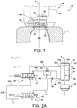
- Figure 1 is a schematic and a partial view illustrating the main components of an apparatus 10 for blowing and filling a container.
- the apparatus 10 comprises a mould 12 enclosing a container 14 such as a bottle.
- a bottle which has been manufactured through blow moulding or stretch-blow moulding comprises a dispensing opening 16 having a neck 18 with an outside thread and a flange or neck ring 20 that is provided at the basis of the neck.
- the container has been shaped so that the dispensing opening 16 protrudes from the mould 12 above it.
- neck ring 20 rests against a shoulder 22 provided at the upper part of the mould around the container 14.
- Apparatus 10 also comprises an injection head 24 which comes into contact with the upper surface of mould 12 or container 14, on the neck ring 20, in the course of performance of the blowing and filling method.
- Injection head 24 comprises an injection valve 26 provided in an inner housing 28.
- Injection head 24 is substantially cylindrical in shape as partially illustrated in Figure 1 and inner housing 28 is also cylindrical in shape and both are coaxial.
- injection valve 26 is in a lower position as illustrated in Figure 1 , in a sealing contact with the inner surface 28a of housing 28 so as to prevent any further flow of liquid into container 14 and ensure liquid tight-sealing.
- a longitudinal axis A which here coincides with the vertical axis, passes by the centre of dispensing opening 16.
- Injection head 24 air and mould 12 are substantially aligned along longitudinal axis A.
- axis A is a symmetry axis to container 14.
- container 14 has been filled with a liquid containing dissolved gas, such as sparkling water or more generally, any kind of carbonated beverage.
- a liquid containing dissolved gas such as sparkling water or more generally, any kind of carbonated beverage.
- container 14 is a plastic container which has been manufactured according to a known method such as disclosed in Applicant's patent EP 1 529 620 B1 .
- a plastic preform is first manufactured through a moulding process and then heated before being positioned within mould 12.
- Mould 12 may be spitted into two or more parts depending on the manufacturing process.
- the preform usually assumes the shape of a cylindrical tube closed at its bottom end and open at its opposite end.
- the open end is shaped during the process, thereby leading to dispensing opening 16.
- the blowing and filling process makes use of a stretch rod (not represented in the drawing) which is downwardly engaged into the open end of the preform so as to come into contact with the closed bottom end thereof.
- the stretch rod is then further actuated to push the closed end downwardly and stretch the preform accordingly in a controlled manner.
- the liquid mentioned above is injected into the preform through its open end around the stretch rod, while the latter is still being actuated.
- This liquid injection causes expansion of the preform together with the movement of the stretch rod until coming into contact with the inner walls of the mould.
- injection head 24 As injection head 24 is in a sealing engagement with dispensing opening 16 and, more particularly, with the upper part of the neck ring 20, moving the injection head away from its sealing position (position represented in Figure 1 ) will rise up the level of liquid in the container and cause foaming and over-spilling all around the dispensing opening.
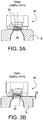
- Figure 2A illustrates a fluid circuit system 30 the aim of which is to control means for moving the injection head represented in Figure 1 .
- injection head 24 has been represented in a very schematic manner for the sake of clarity.
- means for moving injection head 24 comprise an actuator 32 which is here, by way of example, a fluid-operated actuator.
- the injection head is operatively connected to actuator 32 so as to be moved accordingly along longitudinal axis A.
- Fluid-operated actuator 32 more particularly comprises a piston 34 that is sliding longitudinally within a cylindrical housing 36 along longitudinal axis A.
- Piston 34 has a basis 34a and a rod 34b attached thereto on one end and attached to injection head 24 on the opposite end.
- the fluid used for operating actuator 32 is air, for example.
- Fluid circuit system 30 comprises controlling means 38 for controlling the supply of fluid to actuator 32.
- the control of the fluid supply enables appropriate movement of injection head 24.
- axis A coincides with vertical axis and, therefore, the movements of the injection head will be generally referred to as upward and downward movements.
- axis A may be alternatively inclined with respect to vertical axis at an angle that is greater than 0° and less than 90°.
- control means 38 comprise a main valve 40, also denoted OP12. that is connected to actuator 32, respectively at two portions thereof. These two portions 32d and 32e are in communication with separate compartments.
- Control means 38 also comprise an additional secondary valve 42, also denoted OP30, and that is operatively connected to actuator 32.
- Each main valve 40 and secondary valve 42 is connected to a common source of fluid S.
- each valve may occupy two main positions or states, a position in which it is open to allow a flow of fluid passing therethrough and a closed position in which the flow of fluid is obstructed.
- each valve is, for example, an electrical valve of the 5/2 type, i.e. having 5 orifices and 2 positions.
- the return spring 41 enables communication between orifices 1 and 2 (feeding) as well as orifices 4 and 5 (discharge).
- the electrical signal is set to 1, orifices 1 and 4 (feeding) as well as orifices 2 and 3 (discharge) are in communication.
- control means 38 comprise a first fluid line or duct connecting fluid source S to main valve 40 and a second supply line 38b connecting fluid source S to secondary valve 42.
- Control means 38 also comprise another fluid line 38c connecting main valve 40 to the first portion 32d of actuator 32.
- Still another line 38d connects main valve 40 to the second portion 32e of actuator 32.
- This fluid line also comprises a flow regulator 44 (fluid flow rate reducing means) that is arranged in parallel with an anti-return valve 46.
- Control means 38 further comprise a fluid line 38e connecting secondary valve 42 to second portion 32e.
- Fluid line 38e also comprises an anti-return valve 48 Fluid lines 38d and 38e have a common portion 38f that is connected to second portion 32e.
- main valve 40 and secondary valve 42 are arranged in parallel so that the fluid flow rate supplied by secondary valve 42 will add to that supplied by mean valve 40 during the last step of the method according to the invention.
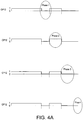
- Figure 3A illustrates the sealing position between injection head 24 and dispensing opening 16 of container 14.
- Figure 3A is identical to Figure 1 .
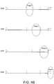
- the method provides for the first step or phase during which injection head 24 is caused to be moved away from the sealing position to a first non-sealing position indicated by 1 in Figure 4C .
- This first non-sealing position is illustrated in Figure 3B and shows that a small gap "g" is left between injection head 24 and neck ring 20.
- This movement away from the sealing position is achieved through controlling the flow of fluid as illustrated in Figure 2B .
- fluid is supplied from fluid source S to main valve 40 through fluid line 38a, then goes through the latter, flows successively through line 38d, flow regulator 44 and common line 38f to reach second portion 32e of actuator 32.
- main valve 40 is forced to close (changing from state 1 to state 0 in Figure 4A ) and secondary valve 42 is maintained in a closed position (state position at 0 in Figure 4B ).
- Fluid is therefore supplied to second compartment 32b of actuator 32, thereby rising up injection head 24 and moving it away from the sealing position.
- fluid flow rate reducing means 44 Thanks to fluid flow rate reducing means 44 the upward movement of injection head 24 is relatively slow and efficiently controlled as represented in Figure 4C .
- This first step triggers venting to atmospheric pressure of dispensing opening 16.
- the aim of this method is to degasify the carbonated liquid contained in container 14 without foaming.
- injection head 24 is forced to move back in a downward movement by operating main valve 40 (changing its status from 0 to 1 to open it), while maintaining secondary valve 42 in its closed position (state position to 0).
- Opening main valve 40 makes it possible for the fluid to go therethrough and flow through fluid line 38c to first portion of actuator 32d.
- Fluid that is present in compartment 32b is therefore expelled through second portion 32e and flows out through successive lines 38f and 38d.
- This arrangement makes it possible to accelerate the return movement of the injection head compared to the movement away during the first step or phase.
- main valve 40 is left open during a given period of time before being closed and the sealing position is held during this period of time.
- the sealing position is maintained for process stabilization purpose.
- the duration of the stabilization step or phase depends on the other steps of moving the injection head so as to enable venting to atmospheric pressure, the velocity of the movements away of the injection head (velocity of cylinder 32) and the liquid or carbonated beverage.
- the method according to the invention provides for subsequent steps or phases to move the injection head away from its sealing position.
- Figure 2D together with Figure 4C illustrate a third step or phase of the method.
- the third step or phase illustrated in Figures 4A-4C is achieved by closing main valve 40 while maintaining secondary valve 42 in a closed position.
- the main valve 40 is maintained in closed position for a longer period of time than the period of time in first step.
- Second non-sealing position 2 depends on several process parameters including the type of liquid.
- This position as well as the first non-sealing position depend on the velocity of the injection head movements and the duration of the steps.
- the velocity of the injection head during the third step or phase may be higher or lower that during the first step or phase, or even equal to, depending on the liquid in the container. Also, the duration of the steps may be adjusted accordingly.
- the method according to the invention provides for a further fourth step or phase which enables acceleration of the movement away of the injection head as illustrated in Figures 2E and 4C .
- injection head 24 is forced to move further away from the Figure 3C sealing position to a further non-sealing position (indicated by 3 in Figure 4C ).
- secondary valve 42 is forced to occupy an open position in which fluid that is supplied by fluid source 5 is sent to secondary valve 42 through line 38b and goes therethrough, it then flows through lines 38e and 38f successively before reaching second portion of actuator 32e.
Landscapes
- Engineering & Computer Science (AREA)
- Mechanical Engineering (AREA)
- Manufacturing & Machinery (AREA)
- Filling Of Jars Or Cans And Processes For Cleaning And Sealing Jars (AREA)
- Basic Packing Technique (AREA)
- Vacuum Packaging (AREA)
- Blow-Moulding Or Thermoforming Of Plastics Or The Like (AREA)
- Fluid-Pressure Circuits (AREA)
Priority Applications (1)
| Application Number | Priority Date | Filing Date | Title |
|---|---|---|---|
| EP12743447.0A EP2741962B1 (en) | 2011-08-08 | 2012-08-02 | Method of degasification of a carbonated beverage-filled container |
Applications Claiming Priority (3)
| Application Number | Priority Date | Filing Date | Title |
|---|---|---|---|
| EP11176854 | 2011-08-08 | ||
| EP12743447.0A EP2741962B1 (en) | 2011-08-08 | 2012-08-02 | Method of degasification of a carbonated beverage-filled container |
| PCT/EP2012/065114 WO2013020883A1 (en) | 2011-08-08 | 2012-08-02 | Method of degasification of a carbonated beverage-filled container |
Publications (2)
| Publication Number | Publication Date |
|---|---|
| EP2741962A1 EP2741962A1 (en) | 2014-06-18 |
| EP2741962B1 true EP2741962B1 (en) | 2019-10-30 |
Family
ID=46614482
Family Applications (1)
| Application Number | Title | Priority Date | Filing Date |
|---|---|---|---|
| EP12743447.0A Active EP2741962B1 (en) | 2011-08-08 | 2012-08-02 | Method of degasification of a carbonated beverage-filled container |
Country Status (9)
| Country | Link |
|---|---|
| US (2) | US9745181B2 (zh) |
| EP (1) | EP2741962B1 (zh) |
| JP (1) | JP6141843B2 (zh) |
| CN (1) | CN103717494B (zh) |
| BR (1) | BR112014000484B1 (zh) |
| CA (1) | CA2836883C (zh) |
| MX (1) | MX348925B (zh) |
| RU (1) | RU2619276C2 (zh) |
| WO (1) | WO2013020883A1 (zh) |
Families Citing this family (5)
| Publication number | Priority date | Publication date | Assignee | Title |
|---|---|---|---|---|
| JP6141843B2 (ja) * | 2011-08-08 | 2017-06-07 | ディスクマ アーゲーDiscma Ag | 炭酸飲料の充填された容器を脱気する方法 |
| WO2017086915A1 (en) | 2015-11-16 | 2017-05-26 | Discma Ag | Method of forming a container using a liquid |
| DE102017109112A1 (de) * | 2017-04-27 | 2018-10-31 | Norgren Ag | Vorrichtung zur Druckluftsteuerung |
| DE102018106779A1 (de) | 2018-03-22 | 2019-09-26 | Krones Ag | Vorrichtung zum Expandieren von Kunststoffbehältnissen mit Absperrventil zwischen Druckerzeugungseinrichtung und Einfülleinrichtung |
| DE102021115729A1 (de) | 2021-06-17 | 2022-12-22 | Krones Aktiengesellschaft | Vorrichtung und Verfahren zum Inspizieren von befüllten Behältnissen und deren Füllgut |
Family Cites Families (59)
| Publication number | Priority date | Publication date | Assignee | Title |
|---|---|---|---|---|
| US1686811A (en) * | 1922-05-15 | 1928-10-09 | Greenhouse Samuel | Bottle-filling machine |
| DE1127241B (de) * | 1960-06-14 | 1962-04-05 | Holstein & Kappert Maschf | Verfahren und Vorrichtung zur Entleerung der unter Druck an Flaschenfuellmaschinen fuer kohlensaeurehaltige Getraenke gefuellten Flaschen |
| NL284490A (zh) * | 1961-10-25 | 1900-01-01 | ||
| DE1482619C3 (de) * | 1965-03-31 | 1975-02-20 | Enzinger-Union-Werke Ag, 6800 Mannheim | Gegendruckfüllorgan zum Abfüllen kohlensäurehaltiger Trinkflüssigkeiten in Gefäße |
| DE1482630A1 (de) * | 1965-12-29 | 1969-01-16 | Holstein & Kappert Maschf | Differenzdruckfuellventil |
| US3645303A (en) * | 1970-09-08 | 1972-02-29 | Ato Inc | Filling apparatus |
| JPS5023472B1 (zh) * | 1970-12-28 | 1975-08-07 | ||
| DE2234120C3 (de) * | 1972-07-12 | 1979-08-09 | Seitz-Werke Gmbh, 6550 Bad Kreuznach | Füllelement mit langem Fallrohr für Mehrkammer-Gegendruckfüllmaschinen |
| GB1474044A (en) * | 1974-12-03 | 1977-05-18 | Ici Ltd | Plastics container manufacture |
| JPS53107794U (zh) * | 1977-02-03 | 1978-08-29 | ||
| DE2800972B2 (de) * | 1978-01-11 | 1980-03-06 | Ortmann & Herbst Gmbh, 2000 Hamburg | Behälterfüllorgan mit Kolben/Zylinder-Hubanordnung |
| US4707966A (en) * | 1981-08-26 | 1987-11-24 | Automatic Liquid Packaging, Inc. | Container with an encapsulated top insert and method and apparatus for making same |
| US4403940A (en) * | 1981-10-28 | 1983-09-13 | The Continental Group, Inc. | Blow head valve |
| US5038548A (en) * | 1983-07-29 | 1991-08-13 | Sieg William F | Defoaming method and apparatus |
| DE3920977A1 (de) * | 1989-06-27 | 1991-01-10 | Alfill Getraenketechnik | Vorrichtung zum fuellen von behaeltern |
| DE4324592C1 (de) | 1993-07-22 | 1995-01-12 | Kronseder Maschf Krones | Verfahren und Vorrichtung zum Einfüllen einer Flüssigkeit in Gefäße |
| JP2856057B2 (ja) * | 1993-12-28 | 1999-02-10 | 東洋製罐株式会社 | 炭酸飲料の充填方法と装置 |
| FR2764544B1 (fr) * | 1997-06-16 | 1999-09-24 | Sidel Sa | Tuyere de soufflage de recipients en matiere plastique et installation pourvue d'une telle tuyere |
| GB9818179D0 (en) * | 1998-08-21 | 1998-10-14 | Univ Manchester | Foam control |
| FR2804059B1 (fr) * | 2000-01-20 | 2002-08-30 | Sidel Sa | Machine de soufflage de recipients comportant des moyens d'orientation des preformes dans le moule de soufflage |
| FR2814392B1 (fr) * | 2000-09-25 | 2002-12-20 | Sidel Sa | Machine d'etirage-soufflage comportant une commande perfectionnee de la tige d'etirage |
| DE20018500U1 (de) * | 2000-10-28 | 2001-12-13 | Krones Ag | Blasmaschine |
| FR2839277B1 (fr) * | 2002-05-03 | 2005-04-08 | Nestle Waters Man & Technology | Procede de fabrication d'un contenant en resine polyester et dispositif pour sa mise en oeuvre |
| ATE423670T1 (de) | 2003-11-06 | 2009-03-15 | Nestle Waters Man & Technology | Herstellungsverfahren von behältern aus polyesterharz |
| FR2876942B1 (fr) * | 2004-10-22 | 2008-08-15 | Sidel Sas | Installation de soufflage pour la fabrication de recipients en matiere thermoplastique |
| EP1877310A2 (en) * | 2005-04-25 | 2008-01-16 | Advanced Technology Materials, Inc. | Material storage and dispensing packages and methods |
| FR2889673B1 (fr) * | 2005-08-12 | 2007-10-26 | Sidel Sas | Installation de soufflage comportant une tuyere equipee d'un joint d'etancheite a levre |
| US8026288B2 (en) * | 2006-01-26 | 2011-09-27 | Toyo Seikan Kaisha, Ltd. | Defoaming method |
| US7914726B2 (en) * | 2006-04-13 | 2011-03-29 | Amcor Limited | Liquid or hydraulic blow molding |
| US8573964B2 (en) * | 2006-04-13 | 2013-11-05 | Amcor Limited | Liquid or hydraulic blow molding |
| JP4990368B2 (ja) * | 2006-11-29 | 2012-08-01 | シデル ホールディングス アンド テクノロジー エスエー | 充填バルブユニット |
| FR2912678B1 (fr) * | 2007-02-16 | 2013-02-15 | Sidel Participations | Tuyere pour une machine de fabrication de recipients |
| FR2914876B1 (fr) * | 2007-04-10 | 2009-07-10 | Sidel Participations | Dispositif de moulage, par soufflage ou etirage-soufflage, de recipients en matiere thermoplastique |
| FR2914875B1 (fr) * | 2007-04-13 | 2009-07-10 | Sidel Participations | Dispositif de moulage pour la fabrication de recipients thermoplastiques par soufflage ou etirage-soufflage. |
| DE102007032434B4 (de) * | 2007-07-10 | 2019-08-22 | Krones Aktiengesellschaft | Blasvorrichtung zum Expandieren von Behältnissen |
| FR2918916B1 (fr) * | 2007-07-19 | 2009-10-23 | Sidel Participations | Installation pour la fabrication de recipients a partir d'une preforme et procede de commande des moyens de soufflage d'une telle installation |
| FR2921582B1 (fr) * | 2007-09-27 | 2013-11-22 | Sidel Participations | Installation de soufflage de recipients en materiau thermoplastique |
| US8017064B2 (en) * | 2007-12-06 | 2011-09-13 | Amcor Limited | Liquid or hydraulic blow molding |
| DE102008028754A1 (de) * | 2008-06-17 | 2009-12-24 | Bernd Hansen | Vorrichtung zum Herstellen und Befüllen von Behältern |
| EP2143543A1 (fr) * | 2008-07-07 | 2010-01-13 | Nestec S.A. | Dispositif et procédé de conditionnement de liquide alimentaire |
| EP2143545A1 (fr) * | 2008-07-07 | 2010-01-13 | Nestec S.A. | Procédé et dispositif de conditionnement d'un liquide alimentaire |
| EP2143542A1 (fr) * | 2008-07-07 | 2010-01-13 | Nestec S.A. | Procédé et dispositif de conditionnement d'un liquide alimentaire |
| FR2940171B1 (fr) * | 2008-12-24 | 2011-01-21 | Sidel Participations | Installation de soufflage pour la fabrication d'un recipient a partir d'une ebauche |
| DE102009011583A1 (de) * | 2009-03-06 | 2010-09-09 | Krones Ag | Verfahren und Vorrichtung zum Herstellen und Befüllen von dünnwandigen Getränkebehältern |
| DE102009014857B4 (de) * | 2009-03-30 | 2014-06-26 | Khs Gmbh | Verfahren zum Füllen von Flaschen oder dergleichen Behältern sowie Füllmaschine |
| FR2943941B1 (fr) * | 2009-04-02 | 2011-04-22 | Sidel Participations | Unite porte-moule avec tuyere pilotee |
| DE102010007541A1 (de) * | 2009-12-23 | 2011-06-30 | KHS Corpoplast GmbH, 22145 | Verfahren und Vorrichtung zur Herstellung von gefüllten Behältern |
| JP5685835B2 (ja) | 2010-06-03 | 2015-03-18 | 株式会社リコー | 滴吐出状態検出装置、画像形成装置、画像形成システム |
| JP5669490B2 (ja) * | 2010-09-10 | 2015-02-12 | 有限会社村上商店 | 発泡性液体の充填装置 |
| EP2463079A1 (en) * | 2010-12-10 | 2012-06-13 | Nestec S.A. | A process for single-step forming and filling of containers |
| JP6141843B2 (ja) * | 2011-08-08 | 2017-06-07 | ディスクマ アーゲーDiscma Ag | 炭酸飲料の充填された容器を脱気する方法 |
| US9254617B2 (en) * | 2011-10-27 | 2016-02-09 | Discma Ag | Method and apparatus for forming and filling a container |
| WO2013096609A1 (en) * | 2011-12-21 | 2013-06-27 | Amcor Limited | A sealing system for molding machine |
| US9610744B2 (en) * | 2011-12-27 | 2017-04-04 | Discma Ag | Blow molding device and a method for manufacturing a container |
| EP2617650B1 (en) * | 2012-01-17 | 2014-08-20 | Nestec S.A. | Apparatus for blowing and filling a container with liquid collecting means |
| WO2013117492A1 (en) * | 2012-02-10 | 2013-08-15 | Nestec S.A. | A method of blowing, filling and capping containers |
| EP2636603A1 (en) * | 2012-03-08 | 2013-09-11 | Nestec S.A. | A method and apparatus for blowing and filling containers with release of liquid overpressure |
| DE102012015087A1 (de) * | 2012-08-01 | 2014-05-15 | Khs Corpoplast Gmbh | Verfahren sowie Vorrichtung zum Herstellen von mit einem flüssigen Füllgut gefüllten Behältern |
| WO2014020042A1 (en) * | 2012-08-03 | 2014-02-06 | Nestec S.A. | Method and apparatus for fabricating containers |
-
2012
- 2012-08-02 JP JP2014524338A patent/JP6141843B2/ja active Active
- 2012-08-02 BR BR112014000484-6A patent/BR112014000484B1/pt active IP Right Grant
- 2012-08-02 RU RU2014108771A patent/RU2619276C2/ru active
- 2012-08-02 MX MX2014000461A patent/MX348925B/es active IP Right Grant
- 2012-08-02 CN CN201280037933.7A patent/CN103717494B/zh active Active
- 2012-08-02 CA CA2836883A patent/CA2836883C/en active Active
- 2012-08-02 EP EP12743447.0A patent/EP2741962B1/en active Active
- 2012-08-02 US US14/236,827 patent/US9745181B2/en active Active
- 2012-08-02 WO PCT/EP2012/065114 patent/WO2013020883A1/en active Application Filing
-
2017
- 2017-04-24 US US15/495,046 patent/US10501302B2/en active Active
Non-Patent Citations (1)
| Title |
|---|
| None * |
Also Published As
| Publication number | Publication date |
|---|---|
| CN103717494A (zh) | 2014-04-09 |
| US20140174032A1 (en) | 2014-06-26 |
| US10501302B2 (en) | 2019-12-10 |
| CA2836883A1 (en) | 2013-02-14 |
| BR112014000484B1 (pt) | 2020-06-30 |
| RU2014108771A (ru) | 2015-09-20 |
| EP2741962A1 (en) | 2014-06-18 |
| BR112014000484A2 (pt) | 2017-02-21 |
| MX2014000461A (es) | 2014-02-20 |
| WO2013020883A1 (en) | 2013-02-14 |
| CN103717494B (zh) | 2015-11-25 |
| CA2836883C (en) | 2019-02-12 |
| JP6141843B2 (ja) | 2017-06-07 |
| US9745181B2 (en) | 2017-08-29 |
| RU2619276C2 (ru) | 2017-05-15 |
| JP2014529551A (ja) | 2014-11-13 |
| MX348925B (es) | 2017-07-03 |
| US20170225934A1 (en) | 2017-08-10 |
Similar Documents
| Publication | Publication Date | Title |
|---|---|---|
| US10501302B2 (en) | Method of degasification of a carbonated beverage-filled container | |
| EP3381654B1 (en) | Liquid blow molding method | |
| WO2017187698A1 (ja) | 液体ブロー成形方法 | |
| CN111511526B (zh) | 装有液体的容器的制造方法 | |
| US10456973B2 (en) | Blow molding apparatus and blow molding method | |
| WO2020044756A1 (ja) | 液体入り容器の製造方法 | |
| EP3685985B1 (en) | Liquid-containing container manufacturing method | |
| JP6853759B2 (ja) | 液体入り容器の製造方法 | |
| JP6840025B2 (ja) | 液体入り容器の製造方法 | |
| JP6809835B2 (ja) | 液体ブロー成形方法 | |
| JP6853758B2 (ja) | 液体入り容器の製造方法 | |
| US20240083092A1 (en) | Method for manufacturing liquid container | |
| JP7026595B2 (ja) | 液体入り容器の製造方法及び製造装置 | |
| JP2022151134A (ja) | 液体入り容器の製造方法 |
Legal Events
| Date | Code | Title | Description |
|---|---|---|---|
| PUAI | Public reference made under article 153(3) epc to a published international application that has entered the european phase |
Free format text: ORIGINAL CODE: 0009012 |
|
| 17P | Request for examination filed |
Effective date: 20140310 |
|
| AK | Designated contracting states |
Kind code of ref document: A1 Designated state(s): AL AT BE BG CH CY CZ DE DK EE ES FI FR GB GR HR HU IE IS IT LI LT LU LV MC MK MT NL NO PL PT RO RS SE SI SK SM TR |
|
| DAX | Request for extension of the european patent (deleted) | ||
| RAP1 | Party data changed (applicant data changed or rights of an application transferred) |
Owner name: DISCMA AG |
|
| STAA | Information on the status of an ep patent application or granted ep patent |
Free format text: STATUS: EXAMINATION IS IN PROGRESS |
|
| 17Q | First examination report despatched |
Effective date: 20170809 |
|
| RAP1 | Party data changed (applicant data changed or rights of an application transferred) |
Owner name: DISCMA AG |
|
| GRAP | Despatch of communication of intention to grant a patent |
Free format text: ORIGINAL CODE: EPIDOSNIGR1 |
|
| STAA | Information on the status of an ep patent application or granted ep patent |
Free format text: STATUS: GRANT OF PATENT IS INTENDED |
|
| INTG | Intention to grant announced |
Effective date: 20190529 |
|
| GRAS | Grant fee paid |
Free format text: ORIGINAL CODE: EPIDOSNIGR3 |
|
| GRAA | (expected) grant |
Free format text: ORIGINAL CODE: 0009210 |
|
| STAA | Information on the status of an ep patent application or granted ep patent |
Free format text: STATUS: THE PATENT HAS BEEN GRANTED |
|
| AK | Designated contracting states |
Kind code of ref document: B1 Designated state(s): AL AT BE BG CH CY CZ DE DK EE ES FI FR GB GR HR HU IE IS IT LI LT LU LV MC MK MT NL NO PL PT RO RS SE SI SK SM TR |
|
| REG | Reference to a national code |
Ref country code: GB Ref legal event code: FG4D |
|
| REG | Reference to a national code |
Ref country code: CH Ref legal event code: EP |
|
| REG | Reference to a national code |
Ref country code: CH Ref legal event code: NV Representative=s name: MICHELI AND CIE SA, CH Ref country code: AT Ref legal event code: REF Ref document number: 1195894 Country of ref document: AT Kind code of ref document: T Effective date: 20191115 |
|
| REG | Reference to a national code |
Ref country code: DE Ref legal event code: R096 Ref document number: 602012065255 Country of ref document: DE |
|
| REG | Reference to a national code |
Ref country code: IE Ref legal event code: FG4D |
|
| REG | Reference to a national code |
Ref country code: LT Ref legal event code: MG4D |
|
| PG25 | Lapsed in a contracting state [announced via postgrant information from national office to epo] |
Ref country code: GR Free format text: LAPSE BECAUSE OF FAILURE TO SUBMIT A TRANSLATION OF THE DESCRIPTION OR TO PAY THE FEE WITHIN THE PRESCRIBED TIME-LIMIT Effective date: 20200131 Ref country code: PL Free format text: LAPSE BECAUSE OF FAILURE TO SUBMIT A TRANSLATION OF THE DESCRIPTION OR TO PAY THE FEE WITHIN THE PRESCRIBED TIME-LIMIT Effective date: 20191030 Ref country code: NO Free format text: LAPSE BECAUSE OF FAILURE TO SUBMIT A TRANSLATION OF THE DESCRIPTION OR TO PAY THE FEE WITHIN THE PRESCRIBED TIME-LIMIT Effective date: 20200130 Ref country code: NL Free format text: LAPSE BECAUSE OF FAILURE TO SUBMIT A TRANSLATION OF THE DESCRIPTION OR TO PAY THE FEE WITHIN THE PRESCRIBED TIME-LIMIT Effective date: 20191030 Ref country code: LT Free format text: LAPSE BECAUSE OF FAILURE TO SUBMIT A TRANSLATION OF THE DESCRIPTION OR TO PAY THE FEE WITHIN THE PRESCRIBED TIME-LIMIT Effective date: 20191030 Ref country code: ES Free format text: LAPSE BECAUSE OF FAILURE TO SUBMIT A TRANSLATION OF THE DESCRIPTION OR TO PAY THE FEE WITHIN THE PRESCRIBED TIME-LIMIT Effective date: 20191030 Ref country code: PT Free format text: LAPSE BECAUSE OF FAILURE TO SUBMIT A TRANSLATION OF THE DESCRIPTION OR TO PAY THE FEE WITHIN THE PRESCRIBED TIME-LIMIT Effective date: 20200302 Ref country code: SE Free format text: LAPSE BECAUSE OF FAILURE TO SUBMIT A TRANSLATION OF THE DESCRIPTION OR TO PAY THE FEE WITHIN THE PRESCRIBED TIME-LIMIT Effective date: 20191030 Ref country code: LV Free format text: LAPSE BECAUSE OF FAILURE TO SUBMIT A TRANSLATION OF THE DESCRIPTION OR TO PAY THE FEE WITHIN THE PRESCRIBED TIME-LIMIT Effective date: 20191030 Ref country code: FI Free format text: LAPSE BECAUSE OF FAILURE TO SUBMIT A TRANSLATION OF THE DESCRIPTION OR TO PAY THE FEE WITHIN THE PRESCRIBED TIME-LIMIT Effective date: 20191030 Ref country code: BG Free format text: LAPSE BECAUSE OF FAILURE TO SUBMIT A TRANSLATION OF THE DESCRIPTION OR TO PAY THE FEE WITHIN THE PRESCRIBED TIME-LIMIT Effective date: 20200130 |
|
| REG | Reference to a national code |
Ref country code: NL Ref legal event code: MP Effective date: 20191030 |
|
| PG25 | Lapsed in a contracting state [announced via postgrant information from national office to epo] |
Ref country code: RS Free format text: LAPSE BECAUSE OF FAILURE TO SUBMIT A TRANSLATION OF THE DESCRIPTION OR TO PAY THE FEE WITHIN THE PRESCRIBED TIME-LIMIT Effective date: 20191030 Ref country code: IS Free format text: LAPSE BECAUSE OF FAILURE TO SUBMIT A TRANSLATION OF THE DESCRIPTION OR TO PAY THE FEE WITHIN THE PRESCRIBED TIME-LIMIT Effective date: 20200229 Ref country code: HR Free format text: LAPSE BECAUSE OF FAILURE TO SUBMIT A TRANSLATION OF THE DESCRIPTION OR TO PAY THE FEE WITHIN THE PRESCRIBED TIME-LIMIT Effective date: 20191030 |
|
| PG25 | Lapsed in a contracting state [announced via postgrant information from national office to epo] |
Ref country code: AL Free format text: LAPSE BECAUSE OF FAILURE TO SUBMIT A TRANSLATION OF THE DESCRIPTION OR TO PAY THE FEE WITHIN THE PRESCRIBED TIME-LIMIT Effective date: 20191030 |
|
| PG25 | Lapsed in a contracting state [announced via postgrant information from national office to epo] |
Ref country code: DK Free format text: LAPSE BECAUSE OF FAILURE TO SUBMIT A TRANSLATION OF THE DESCRIPTION OR TO PAY THE FEE WITHIN THE PRESCRIBED TIME-LIMIT Effective date: 20191030 Ref country code: EE Free format text: LAPSE BECAUSE OF FAILURE TO SUBMIT A TRANSLATION OF THE DESCRIPTION OR TO PAY THE FEE WITHIN THE PRESCRIBED TIME-LIMIT Effective date: 20191030 Ref country code: CZ Free format text: LAPSE BECAUSE OF FAILURE TO SUBMIT A TRANSLATION OF THE DESCRIPTION OR TO PAY THE FEE WITHIN THE PRESCRIBED TIME-LIMIT Effective date: 20191030 Ref country code: RO Free format text: LAPSE BECAUSE OF FAILURE TO SUBMIT A TRANSLATION OF THE DESCRIPTION OR TO PAY THE FEE WITHIN THE PRESCRIBED TIME-LIMIT Effective date: 20191030 |
|
| REG | Reference to a national code |
Ref country code: DE Ref legal event code: R097 Ref document number: 602012065255 Country of ref document: DE |
|
| REG | Reference to a national code |
Ref country code: AT Ref legal event code: MK05 Ref document number: 1195894 Country of ref document: AT Kind code of ref document: T Effective date: 20191030 |
|
| PG25 | Lapsed in a contracting state [announced via postgrant information from national office to epo] |
Ref country code: SK Free format text: LAPSE BECAUSE OF FAILURE TO SUBMIT A TRANSLATION OF THE DESCRIPTION OR TO PAY THE FEE WITHIN THE PRESCRIBED TIME-LIMIT Effective date: 20191030 Ref country code: SM Free format text: LAPSE BECAUSE OF FAILURE TO SUBMIT A TRANSLATION OF THE DESCRIPTION OR TO PAY THE FEE WITHIN THE PRESCRIBED TIME-LIMIT Effective date: 20191030 |
|
| PLBE | No opposition filed within time limit |
Free format text: ORIGINAL CODE: 0009261 |
|
| STAA | Information on the status of an ep patent application or granted ep patent |
Free format text: STATUS: NO OPPOSITION FILED WITHIN TIME LIMIT |
|
| 26N | No opposition filed |
Effective date: 20200731 |
|
| PG25 | Lapsed in a contracting state [announced via postgrant information from national office to epo] |
Ref country code: AT Free format text: LAPSE BECAUSE OF FAILURE TO SUBMIT A TRANSLATION OF THE DESCRIPTION OR TO PAY THE FEE WITHIN THE PRESCRIBED TIME-LIMIT Effective date: 20191030 Ref country code: SI Free format text: LAPSE BECAUSE OF FAILURE TO SUBMIT A TRANSLATION OF THE DESCRIPTION OR TO PAY THE FEE WITHIN THE PRESCRIBED TIME-LIMIT Effective date: 20191030 |
|
| PG25 | Lapsed in a contracting state [announced via postgrant information from national office to epo] |
Ref country code: MC Free format text: LAPSE BECAUSE OF FAILURE TO SUBMIT A TRANSLATION OF THE DESCRIPTION OR TO PAY THE FEE WITHIN THE PRESCRIBED TIME-LIMIT Effective date: 20191030 |
|
| GBPC | Gb: european patent ceased through non-payment of renewal fee |
Effective date: 20200802 |
|
| PG25 | Lapsed in a contracting state [announced via postgrant information from national office to epo] |
Ref country code: LU Free format text: LAPSE BECAUSE OF NON-PAYMENT OF DUE FEES Effective date: 20200802 |
|
| REG | Reference to a national code |
Ref country code: BE Ref legal event code: MM Effective date: 20200831 |
|
| PG25 | Lapsed in a contracting state [announced via postgrant information from national office to epo] |
Ref country code: IE Free format text: LAPSE BECAUSE OF NON-PAYMENT OF DUE FEES Effective date: 20200802 Ref country code: GB Free format text: LAPSE BECAUSE OF NON-PAYMENT OF DUE FEES Effective date: 20200802 Ref country code: BE Free format text: LAPSE BECAUSE OF NON-PAYMENT OF DUE FEES Effective date: 20200831 |
|
| PG25 | Lapsed in a contracting state [announced via postgrant information from national office to epo] |
Ref country code: TR Free format text: LAPSE BECAUSE OF FAILURE TO SUBMIT A TRANSLATION OF THE DESCRIPTION OR TO PAY THE FEE WITHIN THE PRESCRIBED TIME-LIMIT Effective date: 20191030 Ref country code: MT Free format text: LAPSE BECAUSE OF FAILURE TO SUBMIT A TRANSLATION OF THE DESCRIPTION OR TO PAY THE FEE WITHIN THE PRESCRIBED TIME-LIMIT Effective date: 20191030 Ref country code: CY Free format text: LAPSE BECAUSE OF FAILURE TO SUBMIT A TRANSLATION OF THE DESCRIPTION OR TO PAY THE FEE WITHIN THE PRESCRIBED TIME-LIMIT Effective date: 20191030 |
|
| PG25 | Lapsed in a contracting state [announced via postgrant information from national office to epo] |
Ref country code: MK Free format text: LAPSE BECAUSE OF FAILURE TO SUBMIT A TRANSLATION OF THE DESCRIPTION OR TO PAY THE FEE WITHIN THE PRESCRIBED TIME-LIMIT Effective date: 20191030 |
|
| P01 | Opt-out of the competence of the unified patent court (upc) registered |
Effective date: 20230505 |
|
| PGFP | Annual fee paid to national office [announced via postgrant information from national office to epo] |
Ref country code: IT Payment date: 20230720 Year of fee payment: 12 Ref country code: CH Payment date: 20230902 Year of fee payment: 12 |
|
| PGFP | Annual fee paid to national office [announced via postgrant information from national office to epo] |
Ref country code: FR Payment date: 20230720 Year of fee payment: 12 Ref country code: DE Payment date: 20230720 Year of fee payment: 12 |