EP2741306A1 - Identifikationsgeber für ein Schließsystem eines Kraftfahrzeuges mit einer beleuchtbaren Rahmenvorrichtung - Google Patents
Identifikationsgeber für ein Schließsystem eines Kraftfahrzeuges mit einer beleuchtbaren Rahmenvorrichtung Download PDFInfo
- Publication number
- EP2741306A1 EP2741306A1 EP13196051.0A EP13196051A EP2741306A1 EP 2741306 A1 EP2741306 A1 EP 2741306A1 EP 13196051 A EP13196051 A EP 13196051A EP 2741306 A1 EP2741306 A1 EP 2741306A1
- Authority
- EP
- European Patent Office
- Prior art keywords
- frame
- information carrier
- housing
- identification transmitter
- illumination
- Prior art date
- Legal status (The legal status is an assumption and is not a legal conclusion. Google has not performed a legal analysis and makes no representation as to the accuracy of the status listed.)
- Granted
Links
Images



Classifications
-
- H—ELECTRICITY
- H01—ELECTRIC ELEMENTS
- H01H—ELECTRIC SWITCHES; RELAYS; SELECTORS; EMERGENCY PROTECTIVE DEVICES
- H01H9/00—Details of switching devices, not covered by groups H01H1/00 - H01H7/00
- H01H9/18—Distinguishing marks on switches, e.g. for indicating switch location in the dark; Adaptation of switches to receive distinguishing marks
- H01H9/182—Illumination of the symbols or distinguishing marks
-
- H—ELECTRICITY
- H01—ELECTRIC ELEMENTS
- H01H—ELECTRIC SWITCHES; RELAYS; SELECTORS; EMERGENCY PROTECTIVE DEVICES
- H01H9/00—Details of switching devices, not covered by groups H01H1/00 - H01H7/00
- H01H9/02—Bases, casings, or covers
- H01H9/0214—Hand-held casings
- H01H9/0235—Hand-held casings specially adapted for remote control, e.g. of audio or video apparatus
-
- H—ELECTRICITY
- H01—ELECTRIC ELEMENTS
- H01H—ELECTRIC SWITCHES; RELAYS; SELECTORS; EMERGENCY PROTECTIVE DEVICES
- H01H13/00—Switches having rectilinearly-movable operating part or parts adapted for pushing or pulling in one direction only, e.g. push-button switch
- H01H13/70—Switches having rectilinearly-movable operating part or parts adapted for pushing or pulling in one direction only, e.g. push-button switch having a plurality of operating members associated with different sets of contacts, e.g. keyboard
- H01H13/83—Switches having rectilinearly-movable operating part or parts adapted for pushing or pulling in one direction only, e.g. push-button switch having a plurality of operating members associated with different sets of contacts, e.g. keyboard characterised by legends, e.g. Braille, liquid crystal displays, light emitting or optical elements
-
- H—ELECTRICITY
- H01—ELECTRIC ELEMENTS
- H01H—ELECTRIC SWITCHES; RELAYS; SELECTORS; EMERGENCY PROTECTIVE DEVICES
- H01H2209/00—Layers
- H01H2209/046—Properties of the spacer
- H01H2209/06—Properties of the spacer transparent
-
- H—ELECTRICITY
- H01—ELECTRIC ELEMENTS
- H01H—ELECTRIC SWITCHES; RELAYS; SELECTORS; EMERGENCY PROTECTIVE DEVICES
- H01H2217/00—Facilitation of operation; Human engineering
- H01H2217/032—Feedback about selected symbol, e.g. display
-
- H—ELECTRICITY
- H01—ELECTRIC ELEMENTS
- H01H—ELECTRIC SWITCHES; RELAYS; SELECTORS; EMERGENCY PROTECTIVE DEVICES
- H01H2219/00—Legends
- H01H2219/036—Light emitting elements
- H01H2219/044—Edge lighting of layer
-
- H—ELECTRICITY
- H01—ELECTRIC ELEMENTS
- H01H—ELECTRIC SWITCHES; RELAYS; SELECTORS; EMERGENCY PROTECTIVE DEVICES
- H01H2219/00—Legends
- H01H2219/054—Optical elements
- H01H2219/056—Diffuser; Uneven surface
-
- H—ELECTRICITY
- H01—ELECTRIC ELEMENTS
- H01H—ELECTRIC SWITCHES; RELAYS; SELECTORS; EMERGENCY PROTECTIVE DEVICES
- H01H2219/00—Legends
- H01H2219/054—Optical elements
- H01H2219/062—Light conductor
-
- H—ELECTRICITY
- H01—ELECTRIC ELEMENTS
- H01H—ELECTRIC SWITCHES; RELAYS; SELECTORS; EMERGENCY PROTECTIVE DEVICES
- H01H2223/00—Casings
- H01H2223/04—Casings portable; hand held
-
- H—ELECTRICITY
- H01—ELECTRIC ELEMENTS
- H01H—ELECTRIC SWITCHES; RELAYS; SELECTORS; EMERGENCY PROTECTIVE DEVICES
- H01H2231/00—Applications
- H01H2231/026—Car
-
- H—ELECTRICITY
- H01—ELECTRIC ELEMENTS
- H01H—ELECTRIC SWITCHES; RELAYS; SELECTORS; EMERGENCY PROTECTIVE DEVICES
- H01H2231/00—Applications
- H01H2231/032—Remote control
Definitions
- the invention relates to an identification transmitter for a locking system of a motor vehicle, with a housing, on which at least one actuating member is arranged, which cooperates with an operation arranged in the housing interior switching element.
- the invention provides that the housing has a frame device in which an information carrier is held, which is illuminated by the lighting means.
- a frame device is provided which reliably holds the information carrier and at the same time ensures that a reliable and effective illumination of the information carrier can be achieved.
- the frame device can serve as additional protection for the housing of the identification transmitter.
- the housing interior may further be sealed by appropriate sealing means on the housing, wherein it is also conceivable that the seated on the housing frame device may additionally act sealingly.
- the information carrier can, for. B. have image information that can be read by the user from the outside. About the illumination of the information carrier creates a user-friendly presentation of the information carrier.
- the illumination of the information carrier can take place with light of different wavelengths.
- a lighting only takes place by a defined action of the user, for example, when the user touches or actuates an actuating member of the identification transmitter to z.
- B. trigger an unlocking or locking process on the motor vehicle side.
- Different actions on the identification transmitter can furthermore trigger different illumination colors for the information carrier in a further embodiment of the invention.
- a light guide can be arranged on the housing in order to achieve effective illumination of the information carrier; in particular, the light guide can be arranged on the light source on one side and the information carrier on the other side of the light guide.
- the information carrier from the side or from below from the direction of the housing is illuminated, so that the user sees the information carrier that "lights up" directly.
- the optical waveguide is advantageously formed from a polymer optical fiber, which has a low weight, high flexibility, which in addition is insensitive to electromagnetic influences, which means that there is a positive electromagnetic compatibility.
- the frame device is mounted on the housing, wherein the housing has an upper shell and a lower shell, between which the housing interior is, in particular the frame device is attached to the upper shell, in particular the frame device the upper shell is locked.
- sealants are located on the upper and / or lower shell, so that there is a reliable seal inside the housing.
- the light source electronic components such.
- the frame device may at least partially obscure the housing of the identification transmitter.
- the actuating member or the actuating members of the identification transmitter are arranged within the frame device, in particular held by the frame device.
- the invention encompasses the idea that the actuating means or the actuating member can be illuminated via the same lighting means.
- the information carrier can be arranged rigidly and / or immovably on the housing, in particular on the frame device be.
- the information carrier may have image information, letters and / or numbers.
- the identification transmitter according to the invention may comprise a lighting frame on the information carrier, which frames the information carrier, wherein in particular the lighting frame is a part of the light guide.
- the lighting frame may be formed of a polymer, in particular, the lighting frame may be made of a polycarbonate.
- the polycarbonate may be based on 2,2-bis (4-hydroxyphenyl) -propane (bisphenol A), in particular, the lighting frame may be colored.
- bisphenol A 2,2-bis (4-hydroxyphenyl) -propane
- the polycarbonate has phosphorous.
- a particular advantage of the use of polycarbonate in the identification transmitter is that this material is largely resistant to the effects of weathering and radiation.
- the use of the polycarbonate in the identification transmitter has the advantage that it is resistant to water and many mineral acids and aqueous solutions of neutral salts and oxidizing agents.
- the polycarbonate can be relatively easily processed in the injection molding process because of its high viscosity in the melt, in particular, the lighting frame can form a common component with the housing and / or the frame device. It is also conceivable that the lighting frame is attached to the frame device and / or the housing, wherein the material can be glued well with the respective component, for example via an adhesive, in particular a reaction resin adhesive.
- polycarbonate can be reliably fastened by ultrasonic welding and / or high-frequency welding to the housing or to the frame device.
- the identification transmitter according to the invention comprises that the frame device has on its upper side a metallic layer or a metallic coating.
- the metallic coating can, for. B. be printed.
- the illumination frame is aligned almost flush with the information carrier and / or the top of the frame device.
- the information carrier rests on the housing, in particular that the information carrier is attached to the upper shell.
- One possibility is to glue the information carrier to the upper shell.
- the illumination frame can be formed with an optical structure at least on the side facing the upper shell, whereby incident light is reflected in such a way that a uniform illumination of the illumination frame can be achieved, wherein in particular the optical structure is prism-like.
- the image information of the information carrier which may be printed, for example, on the information carrier, are illuminated uniformly via the optical structure.
- the lighting frame and the frame device may be formed as a common component, in particular, the common component may be a 2K plastic part.
- the invention may include that the lighting frame with the housing, in particular with the upper shell, forms a common component, in particular that this is designed as a 2K plastic part.
- the lighting frame may have a transport arm which extends between the lighting means and the lighting frame, wherein in particular the transport arm at the mouth to the lighting frame has a funnel-like shape to reliably couple light into the lighting frame.
- the transport arm can be designed to be flexible so that the transport arm can be aligned individually according to the requirements of the identification transmitter.
- the upper shell has a light-transmitting region.
- the light source which emits light which shines through the light-transmitting area in the direction of the above the upper shell arranged lighting frame.
- the illumination frame in turn ensures that a corresponding illumination of the edge of the information carrier and / or a direct illumination of the information carrier is ensured.
- the identification transmitter according to the invention can be designed such that the illumination frame is covered by the frame device, wherein the illumination frame is formed with a region for coupling out the light, which is directed to the information carrier.
- the frame device is not directly visible from the outside by the user.
- the lighting frame ensures that, for example, the information carrier is reliably illuminated from the side and / or from below, which is seen by the user from outside as a luminous information carrier.
- the illumination frame may be formed with a region for coupling out the light, which is aligned in particular plane to the information carrier and / or the top of the frame device or is formed obliquely to the information carrier.
- the lighting frame may extend through the upper shell of the housing.
- the lighting frame is advantageously attached sealingly to the upper shell.
- the sealing barrier for the housing interior is located on the housing, in particular on the upper shell and the lower shell.
- the frame device can take over additional sealing functions.
- a further embodiment of an identification transmitter can provide that the information carrier is embodied with a hologram which can be illuminated via the illumination frame, in particular that the region of the illumination frame for the decoupling of the light is positioned laterally on the hologram.
- the illumination frame is covered by the frame device, so that the user can only recognize a luminous information carrier.
- the outcoupled light has one of the following colors: blue, green or white. It has been found that the just mentioned colors achieve a particularly effective illumination of a three-dimensional image of the hologram.
- the hologram is formed from a polymer, and particularly advantageous from a polycarbonate, which can also be used as a material for the lighting frame. It is particularly advantageous if the polycarbonate is colored milky, thereby creating a particularly effective three-dimensional image inside the hologram during lighting with the above colors.
- the invention comprises that the information carrier has an information layer and a light-transparent layer, wherein the information layer is arranged between the upper shell of the housing and the light-transparent layer.
- the light transparent layer may, for. B. be a synthetic, glass-like thermoplastic material, in particular PMMA. Due to the good plastic deformability of this material, it has its advantages for the production of the identification transmitter.
- the proposed light-transparent layer of PMMA is characterized as scratch-resistant, which has a particularly good light-transmitting property.
- the identification transmitter can be part of an active-entry system or a passive entry system of a motor vehicle.
- the invention relates to an identification transmitter for a locking system of a motor vehicle, with a housing, and a housing interior, in which a light source is located, wherein the housing has a frame device, in which an information carrier is held, which is illuminated by the bulb.
- a passive entry system the invention relates to an identification transmitter for a locking system of a motor vehicle, with a housing, and a housing interior, in which a light source is located, wherein the housing has a frame device, in which an information carrier is held, which is illuminated by the bulb.
- the upper shell of the housing has a plurality of openings in which the illumination frame is arranged, the openings being separated from one another by webs are separated.
- This embodiment of the housing has been shown particularly easy to install.
- the identification transmitter 1 for a locking system 2 of a motor vehicle 3, which schematically in FIG. 1 is shown.
- the identification transmitter 1 comprises a housing 20, on which at least one actuating member 21st is arranged.
- two actuators 21 are shown, which can trigger a defined function by an operation.
- the motor vehicle 3 communicates with the identification transmitter 1, wherein an authentication query takes place during the communication between the identification transmitter 1 and the motor vehicle 3.
- the safety mechanism of the motor vehicle 3 z. B. make an unlocking or locking the vehicle doors and / or the tailgate and / or the trunk.
- Other functions are conceivable.
- the electronics may include a transmitting and / or receiving unit, inter alia, to allow reliable communication with the motor vehicle 3.
- the electronics has a switching element 23, which via an actuation of one of the actuators 21 according to FIG. 1 is activatable.
- the electronics comprises a lighting means 24, which is located in the housing interior 22. About the bulb 24 can be in FIG. 1 illuminated information carrier 30 illuminate.
- the housing 20 has a frame device 10 in which the information carrier 30 is held.
- the frame device 10 is fixed to the housing 20, wherein the housing 20 according to the embodiment of FIG. 1 from an upper shell 25 and a lower shell 26 is composed. Between the two shells 25, 26 is the housing interior 22, in which the above-mentioned electronics is located.
- the information carrier 30 is rigidly and immovably arranged on the housing 20, wherein the information carrier 30 according to the embodiments of FIG. 4 to FIG. 8 such as FIG. 11 is reliably held on the frame device 10.
- a light guide 40 is provided which achieves reliable illumination of the information carrier 30.
- the light guide 40 is arranged on one side of the light source 24 and associated with the information carrier 30 to the other side, where it includes the information carrier 30 geometrically.
- the information carrier 30 has a lighting frame 41, which framed this information carrier 30, wherein the lighting frame 41 is a part of said light guide 40.
- the light guide 40 is made of a polycarbonate, in the present embodiment of a polycarbonate on 2,2-bis (4-hydroxyphenyl) propane (bisphenol A) formed (Makrolon).
- the illumination frame 41 framed the information carrier 30, wherein the frame device 10 at least partially covers the illumination frame 41.
- the frame device 10 thus has a step or a kind of step and thus reliably holds the illumination frame 41.
- the light 4 radiates directly into the environment to the outside.
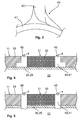
- the coupling of the light 4 from the light source 24, in particular an LED, into the illumination frame 41 can, for example, in accordance with FIG. 2 respectively.
- the lighting frame 41 is in accordance with FIG. 2 formed with a transport arm 43, wherein between the lamp 24 and the lighting frame 41 of the transport arm 43 extends.
- the transport arm 43 has at the mouth to the lighting frame 41 a funnel-like shape 44, which schematically in FIG. 3 is shown to reliably couple light 4 into the lighting frame 41.
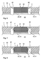
- FIG. 5 a further embodiment of the identification transmitter 1 is shown, wherein the upper shell 25 has openings 28 through which the light guide 40 extends.
- the upper shell 25 has openings 28 through which the light guide 40 extends.
- the frame device 10 completely covers the illumination frame 41, wherein the illumination frame 41 is formed with a region 45 for coupling out the light 4, which is directed laterally to the information carrier 30.
- the information carrier 30 is a hologram, wherein advantageously the light 4 coupled out in the region 45 has one of the following colors: blue, green or white.
- the information carrier 30 has an information layer 32 and a light-transparent layer 33.
- the information layer 32 is disposed between the upper shell 25 of the housing 20 and the light transparent layer 33.
- the information layer 32 may, for. B. on the upper shell 25 or on the underside of the light-transparent layer 33 and have corresponding image information.
- the information carrier 30 can be illuminated reliably via the lateral illumination via the illumination frame 41, the image information 31 of the information layer 32 being clearly visible from the outside.
- FIG. 6 essentially corresponds to the identification transmitter FIG. 4 respectively.
- FIG. 5 wherein the region 45 for coupling out the light 4 runs obliquely.
- the region 45 for coupling out the light 4 is aligned substantially plane to the information carrier 30 and plane to the top 11 of the frame device 10.
- FIG. 11 It is shown that the upper shell 25 of the housing 20 has a light-transmitting region 27 which lies between the light-emitting means 24 and the illumination frame 41.
- the region 4 for coupling out the light 4 is in the same position as in FIG FIG. 4 respectively.
- FIG. 5 It is shown that the upper shell 25 of the housing 20 has a light-transmitting region 27 which lies between the light-emitting means 24 and the illumination frame 41.
- the region 4 for coupling out the light 4 is in the same position as in FIG FIG. 4 respectively.
- FIG. 5
- FIG. 9 the upper shell 25 of the housing 20 is shown, which has a plurality of openings 28 in which the illumination frame 41 can be used according to all embodiments shown.
- the openings 28 to each other are separated by webs 29.
- the geometry of the openings 28 advantageously corresponds to the outer contour of the information carrier 30, whereby a reliable illumination can be achieved.
- the illumination frame 41 is formed on the side facing the upper shell 25 with an optical structure 42, whereby incident light 4 from the light source 24 is reflected within the illumination frame 41, so that a uniform illumination of the illumination frame 41 can be achieved.
- the optical structure 42 is prism-like.
- the identification transmitter 1 has an information carrier 30 which, as in FIG. 7 is held by the frame device 10.
- the information carrier 30 is as in FIG. 7 and FIG. 8 a hologram.
- the information carrier 30 is rigidly and immovably arranged on the housing 20.
- the housing 20 is at least below the information carrier 30 light transparent.
- a lighting means 24 may be arranged directly below the housing 20, so that the information carrier 30 is illuminated from below, at the same time the light 4 exits to the outside.
- a light guide 40 in particular a lighting frame 41 is provided below the housing 20, which can reliably illuminate the information carrier 30 from below.
- the light is coupled into the light guide 40 via a lighting means 24th
- the lighting frame 41 and the frame device 10 are designed as a common component, in particular as a 2K plastic part. It may also be provided that the illumination frame 41 and the housing 20, in particular the upper shell 25, form a common component, in particular a 2K plastic part.
- the information carrier 30 is glued to the upper shell 25, whereby a reliable attachment is effected.
Landscapes
- Engineering & Computer Science (AREA)
- Multimedia (AREA)
- Lock And Its Accessories (AREA)
- Arrangements Of Lighting Devices For Vehicle Interiors, Mounting And Supporting Thereof, Circuits Therefore (AREA)
Abstract
Description
- Die Erfindung betrifft einen Identifikationsgeber für ein Schließsystem eines Kraftfahrzeuges, mit einem Gehäuse, an dem mindestens ein Betätigungsorgan angeordnet ist, das bei einer Betätigung mit einem im Gehäuseinneren angeordneten Schaltelement zusammenwirkt.
- Aus der
DE 10 2007 036 485 A1 ist ein elektronischer Schlüssel eines Schließsystems eines Kraftfahrzeuges offenbart, dessen Betätigungsorgane beleuchtbar sind. Im Gehäuseinneren befindet sich ein Leuchtmittel, welches für die notwendige Umleuchtung des Betätigungsorgans sorgt. Da die Anforderungen bezüglich eines Identifikationsgebers stetig steigen, insbesondere auch andere Bereiche des Identifikationsgebers zu illuminieren sind, ist es notwendig, die in Rede stehenden Identifikationsgeber entsprechend zu verändern bzw. zu modifizieren. - Es ist Aufgabe der vorliegenden Erfindung, einen Identifikationsgeber für ein Schließsystem eines Kraftfahrzeuges zu schaffen, bei dem weitere Abschnitte am Identifikationsgeber beleuchtbar sind, wodurch die Wertigkeit eines Identifikationsgebers sowie die Funktionalität erhöht werden kann, wobei gleichzeitig die Funktionssicherheit des Identifikationsgebers sichergestellt ist.
- Zur Lösung dieser Aufgabe wird ein Identifikationsgeber mit sämtlichen Merkmalen des Anspruchs 1 vorgeschlagen. In den abhängigen Ansprüchen sind bevorzugte Weiterbildungen ausgeführt.
- Dazu ist erfindungsgemäß vorgesehen, dass das Gehäuse eine Rahmenvorrichtung aufweist, in der ein Informationsträger gehalten ist, der durch das Leuchtmittel beleuchtbar ist. Ein wesentlicher Vorteil der Erfindung ist, dass zusätzlich zum Gehäuse eine Rahmenvorrichtung vorgesehen ist, die den Informationsträger zuverlässig hält und gleichzeitig dafür sorgt, dass eine zuverlässige und wirksame Beleuchtung des Informationsträgers erzielbar ist. Die Rahmenvorrichtung kann als zusätzlicher Schutz für das Gehäuse des Identifikationsgebers dienen. Das Gehäuseinnere kann des Weiteren durch entsprechende Dichtmittel am Gehäuse abgedichtet sein, wobei ebenfalls es denkbar ist, dass die am Gehäuse sitzende Rahmenvorrichtung zusätzlich abdichtend wirken kann. Der Informationsträger kann z. B. Bildinformationen aufweisen, die von außen durch den Benutzer ablesbar sind. Über die Beleuchtung des Informationsträgers entsteht eine benutzerfreundliche Präsentation des Informationsträgers. Es ist denkbar, dass die Beleuchtung des Informationsträgers mit Licht unterschiedlicher Wellenlänge erfolgen kann. Zum Beispiel kann vorgesehen sein, dass eine Beleuchtung lediglich durch eine definierte Aktion des Benutzers erfolgt, beispielsweise, wenn der Benutzer ein Betätigungsorgan des Identifikationsgebers berührt bzw. betätigt, um z. B. einen Entriegelungs- oder Verriegelungsvorgang kraftfahrzeugseitig auszulösen. Unterschiedliche Aktionen am Identifikationsgeber können des Weiteren in einer weiteren Ausführungsform der Erfindung unterschiedliche Beleuchtungsfarben für den Informationsträger mit auslösen.
- In einer die Erfindung verbessernden Maßnahme kann ein Lichtleiter am Gehäuse angeordnet sein, um eine wirksame Beleuchtung des Informationsträgers zu erzielen, insbesondere kann zur einen Seite der Lichtleiter am Leuchtmittel angeordnet sein und zur anderen Seite der Lichtleiter dem Informationsträger zugeordnet sein. Das bedeutet, dass z. B. die Umrandung des Informationsträgers beleuchtbar ist. Alternativ und/oder zusätzlich ist es denkbar, dass der Informationsträger von der Seite oder von unten aus der Richtung des Gehäuses beleuchtbar ist, sodass der Benutzer den Informationsträger sieht, der "direkt" leuchtet. Der Lichtwellenleiter ist vorteilhafterweise aus einer polymeroptischen Faser ausgebildet, die ein geringes Gewicht, eine hohe Flexibilität aufweist, wobei diese zusätzlich unempfindlich gegenüber elektromagnetischen Einflüssen ist, das bedeutet, dass eine positive elektromagnetische Verträglichkeit besteht. Zusätzlich kann vorgesehen sein, dass neben der eigentlichen Funktion des Lichtleiters als Beleuchtungsmittel zusätzlich Dateninformationen von außen in den Identifikationsgeber oder aus dem Gehäuseinneren des Identifikationsgebers nach außen Daten übertragbar sind.
- Zudem kann es vorgesehen sein, dass die Rahmenvorrichtung auf dem Gehäuse befestigt ist, wobei das Gehäuse eine obere Schale und eine untere Schale aufweist, zwischen denen das Gehäuseinnere sich befindet, wobei insbesondere die Rahmenvorrichtung an der oberen Schale befestigt ist, wobei insbesondere die Rahmenvorrichtung an der oberen Schale verrastet ist. In der Regel befinden sich Dichtmittel an der oberen und/oder unteren Schale, sodass eine zuverlässige Abdichtung des Gehäuseinneren vorliegt. Im Gehäuseinneren befinden sich beispielsweise das Leuchtmittel, Elektronikbauteile, wie z. B. Leiterplatine, Sende- und/oder Empfangseinheiten, etc.
- Vorteilhafterweise kann die Rahmenvorrichtung zumindest teilweise das Gehäuse des Identifikationsgebers verdecken. Zudem ist es denkbar, dass das Betätigungsorgan bzw. die Betätigungsorgane des Identifikationsgebers innerhalb der Rahmenvorrichtung angeordnet sind, insbesondere durch die Rahmenvorrichtung gehalten sind. Zudem und/oder zusätzlich umschließt die Erfindung den Gedanken, dass über das gleiche Leuchtmittel auch die Betätigungsorgane bzw. das Betätigungsorgan beleuchtbar ist.
- In einer möglichen Ausführungsform der Erfindung kann der Informationsträger starr und/oder unbeweglich am Gehäuse, insbesondere an der Rahmenvorrichtung angeordnet sein. Der Informationsträger kann Bildinformationen, Buchstaben und/oder Zahlen aufweisen.
- Des Weiteren kann der erfindungsgemäße Identifikationsgeber einen Beleuchtungsrahmen am Informationsträger aufweisen, der den Informationsträger umrahmt, wobei insbesondere der Beleuchtungsrahmen ein Teil des Lichtleiters ist. Zum Beispiel kann der Beleuchtungsrahmen aus einem Polymer ausgebildet sein, insbesondere kann der Beleuchtungsrahmen aus einem Polykarbonat ausgeführt sein. Zum Beispiel kann das Polykarbonat auf 2,2-Bis(4-hydroxyphenyl)-propan (Bisphenol A) basieren, insbesondere kann der Beleuchtungsrahmen eingefärbt sein. Zusätzlich ist denkbar, dass das Polykarbonat Phosphorgen aufweist. Ein besonders Vorteil des Einsatzes von Polykarbonat im Identifikationsgeber ist, dass dieser Werkstoff weitgehend beständig gegenüber Einflüssen von Witterung und Strahlung ist. Zudem weist der Einsatz des Polykarbonats im Identifikationsgeber den Vorteil auf, dass gegenüber Wasser und vielen Mineralsäuren und wässrigen Lösungen von neutralen Salzen und Oxidationsmitteln dieses beständig ist. Zudem lässt sich das Polykarbonat im Spritzgussverfahren wegen seiner hohen Viskosität in der Schmelze relativ einfach bearbeiten, insbesondere kann der Beleuchtungsrahmen ein gemeinsames Bauteil mit dem Gehäuse und/oder der Rahmenvorrichtung bilden. Ebenfalls ist es denkbar, dass der Beleuchtungsrahmen an der Rahmenvorrichtung und/oder am Gehäuse befestigt ist, wobei der Werkstoff beispielsweise über einen Klebstoff, insbesondere einen Reaktionsharzklebstoff gut mit dem jeweiligen Bauteil verklebt werden kann. Alternativ ist Polykarbonat über Ultraschallschweißen und/oder Hochfrequenzschweißen am Gehäuse bzw. an der Rahmenvorrichtung zuverlässig befestigbar.
- Zudem umfasst der erfindungsgemäße Identifikationsgeber, dass die Rahmenvorrichtung an seiner Oberseite eine metallische Schicht oder eine metallische Beschichtung aufweist. Die metallische Beschichtung kann z. B. aufgedruckt sein.
- Ebenfalls kann erfindungsgemäß vorgesehen sein, dass der Beleuchtungsrahmen nahezu plan zum Informationsträger und/oder zur Oberseite der Rahmenvorrichtung ausgerichtet ist. Zudem ist es denkbar, dass der Informationsträger auf dem Gehäuse aufliegt, insbesondere dass der Informationsträger an der oberen Schale befestigt ist. Eine Möglichkeit ist, den Informationsträger mit der oberen Schale zu verkleben.
- In einer weiteren, die Erfindung verbessernden Maßnahme kann der Beleuchtungsrahmen zumindest an der der oberen Schale zugewandten Seite mit einer Optikstruktur ausgebildet sein, wodurch einfallendes Licht derart reflektiert wird, so dass eine gleichmäßige Ausleuchtung des Beleuchtungsrahmens erzielbar ist, wobei insbesondere die Optikstruktur prismenartig ausgebildet ist. Hierdurch kann die Bildinformation des Informationsträgers, die beispielsweise am Informationsträger aufgedruckt sein kann, über die Optikstruktur gleichmäßig beleuchtet werden.
- In einer möglichen Ausführungsform der Erfindung können der Beleuchtungsrahmen und die Rahmenvorrichtung als gemeinsames Bauteil ausgebildet sein, insbesondere kann das gemeinsame Bauteil ein 2K-Kunststoffteil sein. Ebenfalls kann die Erfindung mit umfassen, dass der Beleuchtungsrahmen mit dem Gehäuse, insbesondere mit der oberen Schale, ein gemeinsames Bauteil bildet, insbesondere das dieses als ein 2K-Kunststoffteil ausgeführt ist. Durch eine Reduzierung an Bauteilen ergeben sich unter anderem Montagevorteile.
- Vorteilhafterweise kann der Beleuchtungsrahmen einen Transportarm aufweisen, der zwischen dem Leuchtmittel und dem Beleuchtungsrahmen verläuft, wobei insbesondere der Transportarm an der Mündung zum Beleuchtungsrahmen eine trichterartige Form aufweist, um Licht zuverlässig in den Beleuchtungsrahmen einzukoppeln. Der Transportarm kann flexibel ausgestaltet sein, sodass individuell entsprechend den Anforderungen des Identifikationsgebers der Transportarm ausgerichtet werden kann.
- Beispielsweise kann es vorgesehen sein, dass die obere Schale einen Licht transmittierenden Bereich aufweist. Unterhalb des Licht transmittierenden Bereiches befindet sich vorteilhafterweise das Leuchtmittel, welches Licht emittiert, das durch den Licht transmittierenden Bereich in Richtung des oberhalb der oberen Schale angeordneten Beleuchtungsrahmen scheint. Der Beleuchtungsrahmen wiederum sorgt dafür, dass eine entsprechende Beleuchtung des Randes des Informationsträgers und/oder eine direkte Beleuchtung des Informationsträgers sichergestellt ist.
- Ebenfalls kann der erfindungsgemäße Identifikationsgeber derart ausgebildet sein, dass der Beleuchtungsrahmen durch die Rahmenvorrichtung verdeckt ist, wobei der Beleuchtungsrahmen mit einem Bereich zur Auskopplung des Lichts ausgebildet ist, der zum Informationsträger gerichtet ist. Bei dieser Ausgestaltung der Erfindung ist die Rahmenvorrichtung nicht direkt durch den Benutzer von außen sichtbar. Der Beleuchtungsrahmen sorgt dafür, dass beispielsweise der Informationsträger von der Seite und/oder von unten zuverlässig beleuchtet wird, welches durch den Benutzer von außen als leuchtender Informationsträger gesehen wird.
- Vorteilhafterweise kann der Beleuchtungsrahmen mit einem Bereich zur Auskopplung des Lichts ausgebildet sein, der insbesondere plan zum Informationsträger und/oder zur Oberseite der Rahmenvorrichtung ausgerichtet ist oder schräg zum Informationsträger ausgebildet ist. Zudem kann sich der Beleuchtungsrahmen durch die obere Schale des Gehäuses erstrecken. Der Beleuchtungsrahmen ist vorteilhafterweise an der oberen Schale abdichtend befestigt. Vorteilhafterweise befindet sich die Dichtungsbarriere für das Gehäuseinnere am Gehäuse, insbesondere an der oberen Schale und der unteren Schale. Selbstverständlich ist es denkbar, dass die Rahmenvorrichtung Dichtfunktionen zusätzlich mit übernehmen kann.
- Eine weitere Ausführungsform eines Identifikationsgebers kann vorsehen, dass der Informationsträger mit einem Hologramm ausgeführt ist, das über den Beleuchtungsrahmen beleuchtbar ist, insbesondere dass der Bereich des Beleuchtungsrahmens zur Auskopplung des Lichts seitlich am Hologramm positioniert ist. Hierbei ist es denkbar, dass der Beleuchtungsrahmen durch die Rahmenvorrichtung verdeckt ist, sodass der Benutzer lediglich einen leuchtenden Informationsträger erkennen kann. Vorteilhafterweise hat sich gezeigt, dass das ausgekoppelte Licht eine der folgenden Farben aufweist: blau, grün oder weiß. Es hat sich gezeigt, dass die gerade soeben genannten Farben eine besonders effektive Beleuchtung eines dreidimensionalen Abbildes des Hologramms erzielen. Besonders vorteilhaft ist, wenn das Hologramm aus einem Polymer ausgebildet ist, und zwar besonders vorteilhaft aus einem Polykarbonat, welches auch als Material für den Beleuchtungsrahmen zum Einsatz kommen kann. Besonders vorteilhaft ist, wenn das Polykarbonat milchig eingefärbt ist, hierdurch entsteht ein besonders effektives dreidimensionales Bild innerhalb des Hologramms während der Beleuchtung mit den oben genannten Farben.
- Ebenfalls umfasst die Erfindung, dass der Informationsträger eine Informationsschicht und eine lichttransparente Schicht aufweist, wobei die Informationsschicht zwischen der oberen Schale des Gehäuses und der lichttransparenten Schicht angeordnet ist. Die lichttransparente Schicht kann z. B. ein synthetischer, glasähnlicher thermoplastischer Kunststoff sein, insbesondere PMMA. Aufgrund der guten plastischen Verformbarkeit dieses Werkstoffs weist es seine Vorteile für die Produktion des Identifikationsgebers auf. Zudem zeichnet sich die vorgeschlagene lichttransparente Schicht aus PMMA als kratzunempfindlich aus, die eine besonders gute Licht transmittierende Eigenschaft aufweist.
- Der Identifikationsgeber kann Bestandteil eines Active-Entry-Systems oder eines Passiv-Entry-Systems eines Kraftfahrzeuges sein. Im Falle eines Passiv-Entry-Systems bezieht sich die Erfindung auf einen Identifikationsgeber für ein Schließsystem eines Kraftfahrzeuges, mit einem Gehäuse, und einem Gehäuseinneren, in dem sich ein Leuchtmittel befindet, wobei das Gehäuse eine Rahmenvorrichtung aufweist, in der ein Informationsträger gehalten ist, der durch das Leuchtmittel beleuchtbar ist. In den abhängigen Patentansprüchen 2 bis 23 sind mögliche Ausgestaltungen der Erfindung genannt, die sich auf diesen Identifikationsgeber mitbeziehen lassen.
- Damit zuverlässig und effektiv das Licht vom Leuchtmittel, das sich im Gehäuseinneren befindet, zum Informationsträger geleitet wird, kann es vorgesehen sein, dass die obere Schale des Gehäuses eine Vielzahl an Öffnungen aufweist, in denen der Beleuchtungsrahmen angeordnet ist, wobei die Öffnungen durch Stege voneinander getrennt sind. Diese Ausgestaltung des Gehäuses hat sich besonders montagefreundlich gezeigt.
- Weitere Vorteile, Merkmale und Einzelheiten der Erfindung ergeben sich aus der nachfolgenden Beschreibung. Unter Bezugnahme auf die Zeichnungen sind mehrere Ausführungsbeispiele der Erfindung im Einzelnen beschrieben. Dabei können die in den Ansprüchen und in der Beschreibung erwähnten Merkmale jeweils einzeln für sich oder in beliebiger Kombination erfindungswesentlich sein. Es zeigen:
- Fig.1
- eine schematische Ansicht auf einen Identifikationsgeber mit einem Informationsträger, der in einer Rahmenvorrichtung des Identifikationsgebers gehalten ist,
- Fig. 2
- eine schematische Ansicht auf einen Identifikationsgeber, dessen Informationsträger durch einen Beleuchtungsrahmen beleuchtbar ist,
- Fig. 3
- eine Detailansicht bezüglich eines Beleuchtungsrahmens,
- Fig. 4
- eine mögliche Ausführungsform des Identifikationsgebers in Schnittansicht,
- Fig. 5
- eine weitere Ausführungsform bezüglich eines Identifikationsgebers,
- Fig. 6
- eine weitere Ausführungsform bezüglich eines Identifikationsgebers,
- Fig. 7
- eine weitere Ausführungsform bezüglich eines Identifikationsgebers,
- Fig. 8
- eine weitere Ausführungsform bezüglich eines Identifikationsgebers,
- Fig. 9
- eine Draufsicht auf das Gehäuse des Identifikationsgebers in einer möglichen Ausführungsform,
- Fig. 10
- eine Detailansicht bezüglich des Beleuchtungsrahmens in einem weiteren Ausführungsbeispiel,
- Fig. 11
- eine weitere Ausführungsform bezüglich eines Identifikationsgebers und
- Fig. 12
- eine weitere Ausführungsform bezüglich eines Identifikationsgebers.
- Sämtliche Ausführungsbeispiele beziehen sich auf einen Identifikationsgeber 1 für ein Schließsystem 2 eines Kraftfahrzeuges 3, welches schematisch in
Figur 1 gezeigt ist. Der Identifikationsgeber 1 umfasst ein Gehäuse 20, an dem mindestens ein Betätigungsorgan 21 angeordnet ist. Im vorliegenden Ausführungsbeispiel gemäßFigur 1 sind zwei Betätigungsorgane 21 dargestellt, die durch eine Betätigung eine definierte Funktion auslösen können. Hierbei kommuniziert das Kraftfahrzeug 3 mit dem Identifikationsgeber 1, wobei eine Authentifizierungsabfrage während der Kommunikation zwischen Identifikationsgeber 1 und dem Kraftfahrzeug 3 erfolgt. Bei einer positiven Authentifizierung kann der Sicherheitsmechanismus des Kraftfahrzeuges 3 z. B. eine Entriegelung oder Verriegelung der Fahrzeugtüren und/oder der Heckklappe und/oder des Kofferraumes vornehmen. Weitere Funktionen sind denkbar. - Innerhalb des Identifikationsgebers 1 befindet sich eine nicht explizit dargestellte Elektronik, die unter anderem eine Sende- und/oder Empfangseinheit aufweisen kann, um eine zuverlässige Kommunikation mit dem Kraftfahrzeug 3 zu ermöglichen. Gemäß
Figur 2 weist die Elektronik ein Schaltelement 23 auf, welches über eine Betätigung eines der Betätigungsorgane 21 gemäßFigur 1 aktivierbar ist. Ferner umfasst die Elektronik ein Leuchtmittel 24, das sich im Gehäuseinneren 22 befindet. Über das Leuchtmittel 24 lässt sich ein inFigur 1 dargestellter Informationsträger 30 illuminieren. GemäßFigur 1 und Figur 2 ist verdeutlicht, dass das Gehäuse 20 eine Rahmenvorrichtung 10 aufweist, in der der Informationsträger 30 gehalten ist. - Die Rahmenvorrichtung 10 ist am Gehäuse 20 befestigt, wobei das Gehäuse 20 gemäß des Ausführungsbeispiels aus
Figur 1 aus einer oberen Schale 25 und einer unteren Schale 26 sich zusammensetzt. Zwischen den beiden Schalen 25, 26 befindet sich das Gehäuseinnere 22, in dem sich die oben genannte Elektronik befindet. Der Informationsträger 30 ist starr und unbeweglich am Gehäuse 20 angeordnet, wobei der Informationsträger 30 gemäß der Ausführungsbeispiele ausFigur 4 bis Figur 8 sowieFigur 11 zuverlässig an der Rahmenvorrichtung 10 gehalten ist. InFigur 1 und Figur 2 ist ein Lichtleiter 40 vorgesehen, der eine zuverlässige Beleuchtung des Informationsträgers 30 erzielt. GemäßFigur 2 ist der Lichtleiter 40 zu einer Seite hin am Leuchtmittel 24 angeordnet und zur anderen Seite dem Informationsträger 30 zugeordnet, wo es den Informationsträger 30 geometrisch umfasst. Hierbei weist der Informationsträger 30 einen Beleuchtungsrahmen 41 auf, der diesen Informationsträger 30 umrahmt, wobei der Beleuchtungsrahmen 41 ein Teil des genannten Lichtleiters 40 ist. - Der Lichtleiter 40 ist aus einem Polykarbonat, im vorliegenden Ausführungsbeispiel aus einem Polykarbonat auf 2,2-Bis(4-hydroxyphenyl)-propan (Bisphenol A) ausgebildet (Makrolon).
- Im Ausführungsbeispiel gemäß
Figur 4 ist gezeigt, dass der Beleuchtungsrahmen 41 den Informationsträger 30 umrahmt, wobei zumindest teilweise die Rahmenvorrichtung 10 den Beleuchtungsrahmen 41 überdeckt. Die Rahmenvorrichtung 10 weist somit einen Absatz oder eine Art Stufe auf und hält somit zuverlässig den Beleuchtungsrahmen 41. Bei der Illumination strahlt das Licht 4 unmittelbar in die Umgebung nach außen. Die Einkopplung des Lichts 4 vom Leuchtmittel 24, insbesondere einer LED, in den Beleuchtungsrahmen 41 kann beispielsweise gemäßFigur 2 erfolgen. - Damit eine zuverlässige Einkopplung im Bereich des Leuchtmittels 24 erfolgt, ist der Beleuchtungsrahmen 41 gemäß
Figur 2 mit einem Transportarm 43 ausgebildet, wobei zwischen dem Leuchtmittel 24 und dem Beleuchtungsrahmen 41 der Transportarm 43 verläuft. Der Transportarm 43 weist an der Mündung zum Beleuchtungsrahmen 41 eine trichterartige Form 44 auf, die schematisch inFigur 3 gezeigt ist, um Licht 4 zuverlässig in den Beleuchtungsrahmen 41 einzukoppeln. - Gemäß der
Figur 5 ist eine weitere Ausführungsform des Identifikationsgebers 1 gezeigt, wobei die obere Schale 25 Öffnungen 28 aufweist, durch die der Lichtleiter 40 verläuft. Wie inFigur 4 erfolgt eine Emittierung des Lichts 4 in den Außenbereich des Identifikationsgebers 1, wobei zuverlässig der Informationsträger 30 in seinem Außenbereich beleuchtet wird. - Gemäß
Figur 7 und Figur 8 verdeckt die Rahmenvorrichtung 10 vollständig den Beleuchtungsrahmen 41, wobei der Beleuchtungsrahmen 41 mit einem Bereich 45 zur Auskopplung des Lichts 4 ausgebildet ist, der seitlich zum Informationsträger 30 gerichtet ist. Der Informationsträger 30 ist im vorliegenden Ausführungsbeispiel ein Hologramm, wobei vorteilhafterweise das im Bereich 45 ausgekoppelte Licht 4 eines der folgenden Farben aufweist: blau, grün oder weiß. - Gemäß
Figur 8 weist der Informationsträger 30 eine Informationsschicht 32 und eine lichttransparente Schicht 33 auf. Die Informationsschicht 32 ist zwischen der oberen Schale 25 des Gehäuses 20 und der lichttransparenten Schicht 33 angeordnet. Die Informationsschicht 32 kann z. B. auf der oberen Schale 25 oder auf der Unterseite der lichttransparenten Schicht 33 aufgedruckt sein und entsprechende Bildinformationen aufweisen. Über die seitliche Beleuchtung über den Beleuchtungsrahmen 41 lässt sich der Informationsträger 30 zuverlässig illuminieren, wobei gut sichtbar die Bildinformationen 31 der Informationsschicht 32 von außen sichtbar werden. - Das Ausführungsbeispiel gemäß
Figur 6 entspricht im Wesentlichen dem Identifikationsgeber ausFigur 4 bzw.Figur 5 , wobei der Bereich 45 zur Auskopplung des Lichts 4 schräg verläuft. GemäßFigur 4 und Figur 5 ist der Bereich 45 zur Auskopplung des Lichts 4 im Wesentlichen plan zum Informationsträger 30 sowie plan zur Oberseite 11 der Rahmenvorrichtung 10 ausgerichtet. - In
Figur 11 ist gezeigt, dass die obere Schale 25 des Gehäuses 20 einen Licht transmittierenden Bereich 27 aufweist, der zwischen dem Leuchtmittel 24 und dem Beleuchtungsrahmen 41 liegt. Der Bereich 45 zur Auskopplung des Lichtes 4 befindet sich in der gleichen Position wie inFigur 4 bzw.Figur 5 . - In
Figur 9 ist die obere Schale 25 des Gehäuses 20 gezeigt, die eine Vielzahl an Öffnungen 28 aufweist, in denen der Beleuchtungsrahmen 41 gemäß aller gezeigten Ausführungsbeispiele einsetzbar ist. Die Öffnungen 28 zueinander sind durch Stege 29 voneinander getrennt. Die Geometrie der Öffnungen 28 entspricht vorteilhafterweise der Außenkontur des Informationsträgers 30, wodurch eine zuverlässige Beleuchtung erzielbar ist. - Gemäß
Figur 10 ist der Beleuchtungsrahmen 41 an der der oberen Schale 25 zugewandten Seite mit einer Optikstruktur 42 ausgebildet, wodurch einfallendes Licht 4 vom Leuchtmittel 24 aus derart innerhalb des Beleuchtungsrahmens 41 reflektiert wird, sodass eine gleichmäßige Ausleuchtung des Beleuchtungsrahmens 41 erzielbar ist. GemäßFigur 10 ist die Optikstruktur 42 prismenartig ausgebildet. - In
Figur 12 weist der Identifikationsgeber 1 einen Informationsträger 30 auf, der wie inFigur 7 durch die Rahmenvorrichtung 10 gehalten ist. Der Informationsträger 30 ist wie inFigur 7 und Figur 8 ein Hologramm. Der Informationsträger 30 ist starr und unbeweglich am Gehäuse 20 angeordnet. Im vorliegenden Ausführungsbeispiel ist das Gehäuse 20 zumindest unterhalb des Informationsträgers 30 lichttransparent ausgeführt. Beispielsweise kann ein Leuchtmittel 24 direkt unterhalb des Gehäuses 20 angeordnet sein, damit der Informationsträger 30 von unten beleuchtbar ist, wobei gleichzeitig das Licht 4 nach außen austritt. Ebenfalls umschließt das inFigur 12 dargestellte Ausführungsbeispiel, dass ein Lichtleiter 40, insbesondere ein Beleuchtungsrahmen 41 unterhalb des Gehäuses 20 vorgesehen ist, der den Informationsträger 30 zuverlässig von unten beleuchten kann. Wie auch bei den anderen Ausführungsbeispielen erfolgt die Lichteinkopplung in den Lichtleiter 40 über ein Leuchtmittel 24. - Gemäß sämtlicher Ausführungsbeispiele ist es denkbar, dass der Beleuchtungsrahmen 41 und die Rahmenvorrichtung 10 als gemeinsames Bauteil, insbesondere als 2K-Kunststoffteil ausgeführt sind. Ebenfalls kann es vorgesehen sein, dass der Beleuchtungsrahmen 41 und das Gehäuse 20, insbesondere die obere Schale 25, ein gemeinsames Bauteil, insbesondere ein 2K-Kunststoffteil bilden.
- Denkbar ist, dass der Informationsträger 30 an der oberen Schale 25 verklebt ist, wodurch eine zuverlässige Befestigung bewirkbar ist.
-
- 1
- Identifikationsgeber
- 2
- Schließsystem
- 3
- Kraftfahrzeug
- 4
- Licht
- 10
- Rahmenvorrichtung
- 11
- Oberseite
- 20
- Gehäuse
- 21
- Betätigungsorgan
- 22
- Gehäuseinnere
- 23
- Schaltelement
- 24
- Leuchtmittel
- 25
- obere Schale
- 26
- untere Schale
- 27
- Licht transmittierender Bereich
- 28
- Öffnung für 40
- 29
- Steg
- 30
- Informationsträger
- 31
- Bildinformation
- 32
- Informationsschicht
- 33
- lichttransparente Schicht
- 40
- Lichtleiter
- 41
- Beleuchtungsrahmen
- 42
- Optikstruktur
- 43
- Transportarm
- 44
- trichterartige Form
- 45
- Bereich zur Auskopplung des Lichts
Claims (15)
- Identifikationsgeber (1) für ein Schließsystem (2) eines Kraftfahrzeuges (3), mit einem Gehäuse (20), an dem mindestens ein Betätigungsorgan (21) angeordnet ist, das bei einer Betätigung mit einem im Gehäuseinneren (22) angeordneten Schaltelement (23) zusammenwirkt,
einem im Gehäuseinneren (22) befindlichen Leuchtmittel (24),
dadurch gekennzeichnet,
dass das Gehäuse (20) eine Rahmenvorrichtung (10) aufweist, in der ein Informationsträger (30) gehalten ist, der durch das Leuchtmittel (24) beleuchtbar ist. - Identifikationsgeber (1) nach Anspruch 1,
dadurch gekennzeichnet,
dass ein Lichtleiter (40) am Gehäuse (20) angeordnet ist, um eine zuverlässige Beleuchtung des Informationsträgers (30) zu erzielen, insbesondere dass zur einen Seite der Lichtleiter (40) am Leuchtmittel (24) angeordnet ist und zur anderen Seite der Lichtleiter (40) dem Informationsträger (30) zugeordnet ist. - Identifikationsgeber (1) nach Anspruch 1 oder 2,
dadurch gekennzeichnet,
dass die Rahmenvorrichtung (10) auf dem Gehäuse (20) befestigt ist, wobei das Gehäuse (20) eine obere Schale (25) und eine untere Schale (26) aufweist, zwischen denen das Gehäuseinnere (22) sich befindet, wobei insbesondere die Rahmenvorrichtung (10) an der oberen Schale (25) befestigt ist, insbesondere dass die Rahmenvorrichtung (10) an der oberen Schale (25) verrastet ist,
wobei insbesondere die obere Schale (25) einen Licht (4) transmittierenden Bereich (27) aufweist. - Identifikationsgeber (1) nach einem der vorhergehenden Ansprüche,
dadurch gekennzeichnet,
dass der Informationsträger (30) starr und/oder unbeweglich am Gehäuse (20), insbesondere an der Rahmenvorrichtung (10) angeordnet ist
und/oder dass der Informationsträger (30) einen Beleuchtungsrahmen (41) aufweist, der den Informationsträger (30) umrahmt, wobei insbesondere der Beleuchtungsrahmen (41) ein Teil des Lichtleiters (40) ist. - Identifikationsgeber (1) nach einem der vorhergehenden Ansprüche,
dadurch gekennzeichnet,
dass der Beleuchtungsrahmen (41) aus einem Polymer ausgebildet ist, insbesondere dass der Beleuchtungsrahmen (41) aus einem Polykarbonat ausgeführt ist und/oder dass das Polykarbonat auf 2,2-Bis(4-hydroxyphenyl)-propan (Bisphenol A) basiert, insbesondere dass der Beleuchtungsrahmen (41) eingefärbt ist. - Identifikationsgeber (1) nach einem der vorhergehenden Ansprüche,
dadurch gekennzeichnet,
dass die Rahmenvorrichtung (10) an seiner Oberseite (11) eine metallische Schicht oder eine metallische Beschichtung aufweist. - Identifikationsgeber (1) nach einem der vorhergehenden Ansprüche,
dadurch gekennzeichnet,
dass der Beleuchtungsrahmen (41) nahezu plan zum Informationsträger (30) und/oder zur Oberseite (11) der Rahmenvorrichtung (10) ausgerichtet ist und/oder dass der Informationsträger (30) auf dem Gehäuse (20) aufliegt, insbesondere dass der Informationsträger (30) an der oberen Schale (25) befestigt ist. - Identifikationsgeber (1) nach einem der vorhergehenden Ansprüche,
dadurch gekennzeichnet,
dass am Informationsträger (30) Bildinformationen (31) gedruckt sind. - Identifikationsgeber (1) nach einem der vorhergehenden Ansprüche,
dadurch gekennzeichnet,
dass der Beleuchtungsrahmen (41) zumindest an der der oberen Schale (25) zugewandten Seite mit einer Optikstruktur (42) ausgebildet ist, wodurch einfallendes Licht (4) derart reflektiert wird, so dass eine gleichmäßige Ausleuchtung des Beleuchtungsrahmens (41) erzielbar ist, wobei insbesondere die Optikstruktur (42) prismenartig ausgebildet ist. - Identifikationsgeber (1) nach einem der vorhergehenden Ansprüche,
dadurch gekennzeichnet,
dass der Beleuchtungsrahmen (41) und die Rahmenvorrichtung (10) als gemeinsames Bauteil ausgebildet sind, insbesondere dass das gemeinsame Bauteil ein 2K-Kunststoffteil ist. - Identifikationsgeber (1) nach einem der vorhergehenden Ansprüche,
dadurch gekennzeichnet,
dass der Beleuchtungsrahmen (41) einen Transportarm (43) aufweist, der zwischen dem Leuchtmittel (24) und dem Beleuchtungsrahmen (41) verläuft, wobei insbesondere der Transportarm (43) an der Mündung zum Beleuchtungsrahmen (41) eine trichterartige Form (44) aufweist, um Licht (4) zuverlässig in den Beleuchtungsrahmen (41) einzukoppeln. - Identifikationsgeber (1) nach einem der vorhergehenden Ansprüche,
dadurch gekennzeichnet,
dass der Beleuchtungsrahmen (41) durch die Rahmenvorrichtung (10) verdeckt ist, wobei der Beleuchtungsrahmen (41) mit einem Bereich (45) zur Auskopplung des Lichts (4) ausgebildet ist, der zum Informationsträger (30) gerichtet ist und/oder dass der Beleuchtungsrahmen (41) mit einem Bereich (45) zur Auskopplung des Lichts (4) ausgebildet ist, der insbesondere plan zum Informationsträger (30) und/oder zur Oberseite (11) der Rahmenvorrichtung (10) ausgerichtet ist oder schräg zum Informationsträger (30) ausgebildet ist. - Identifikationsgeber (1) nach einem der vorhergehenden Ansprüche,
dadurch gekennzeichnet,
dass der Beleuchtungsrahmen (41) und das Gehäuse (20), insbesondere die obere Schale (25) ein gemeinsames Bauteil bilden, insbesondere als ein 2K-Kunststoffteil ausgeführt sind. - Identifikationsgeber (1) nach einem der vorhergehenden Ansprüche,
dadurch gekennzeichnet,
dass sich der Beleuchtungsrahmen (41) durch die obere Schale (25) des Gehäuses (20) erstreckt
und/oder dass der Informationsträger (30) mit einem Hologramm ausgeführt ist, das über den Beleuchtungsrahmen (41) beleuchtbar ist, insbesondere dass der Bereich (45) des Beleuchtungsrahmens (41) zur Auskopplung des Lichts (4) seitlich am Hologramm positioniert ist
und/oder dass das ausgekoppelte Licht (4) eines der folgenden Farben aufweist: blau, grün oder weiß. - Identifikationsgeber (1) nach einem der vorhergehenden Ansprüche,
dadurch gekennzeichnet,
dass der Informationsträger (30) eine Informationsschicht (32) und eine lichttransparente Schicht (33) aufweist, wobei die Informationsschicht (32) zwischen der oberen Schale (25) des Gehäuses (20) und der lichttransparenten Schicht (33) angeordnet ist und/oder dass die obere Schale (25) des Gehäuses (20) eine Vielzahl an Öffnungen (28) aufweist, in denen der Beleuchtungsrahmen (41) angeordnet ist, wobei die Öffnungen (28) durch Stege (29) voneinander getrennt sind.
Applications Claiming Priority (1)
| Application Number | Priority Date | Filing Date | Title |
|---|---|---|---|
| DE102012111906.6A DE102012111906A1 (de) | 2012-12-06 | 2012-12-06 | Identifikationsgeber für ein Schließsystem eines Kraftfahrzeuges mit einer beleuchtbaren Rahmenvorrichtung |
Publications (2)
| Publication Number | Publication Date |
|---|---|
| EP2741306A1 true EP2741306A1 (de) | 2014-06-11 |
| EP2741306B1 EP2741306B1 (de) | 2017-03-22 |
Family
ID=49726590
Family Applications (1)
| Application Number | Title | Priority Date | Filing Date |
|---|---|---|---|
| EP13196051.0A Active EP2741306B1 (de) | 2012-12-06 | 2013-12-06 | Identifikationsgeber für ein Schließsystem eines Kraftfahrzeuges mit einer beleuchtbaren Rahmenvorrichtung |
Country Status (3)
| Country | Link |
|---|---|
| EP (1) | EP2741306B1 (de) |
| CN (1) | CN103847692B (de) |
| DE (1) | DE102012111906A1 (de) |
Citations (4)
| Publication number | Priority date | Publication date | Assignee | Title |
|---|---|---|---|---|
| DE102007036485A1 (de) | 2006-08-05 | 2008-02-07 | Marquardt Gmbh | Gehäuse, insbesondere für einen elektronischen Schlüssel |
| DE102006049455A1 (de) * | 2006-10-17 | 2008-04-24 | Conti Temic Microelectronic Gmbh | Baugruppe mit einem Tastenfeld mit zumindest einem Tastenelement |
| DE102008036531A1 (de) * | 2008-08-06 | 2010-02-11 | Huf Hülsbeck & Fürst Gmbh & Co. Kg | Mobiler Identifikationsgeber |
| FR2936635A1 (fr) * | 2008-10-01 | 2010-04-02 | Valeo Securite Habitacle | Module d'identification pour vehicule automobile. |
Family Cites Families (2)
| Publication number | Priority date | Publication date | Assignee | Title |
|---|---|---|---|---|
| CN202596285U (zh) * | 2011-12-30 | 2012-12-12 | 伟速达(福州)安全系统有限公司 | 车用智能钥匙结构 |
| CN102535964A (zh) * | 2011-12-30 | 2012-07-04 | 伟速达(福州)安全系统有限公司 | 车用智能钥匙结构 |
-
2012
- 2012-12-06 DE DE102012111906.6A patent/DE102012111906A1/de not_active Withdrawn
-
2013
- 2013-12-06 EP EP13196051.0A patent/EP2741306B1/de active Active
- 2013-12-06 CN CN201310656041.1A patent/CN103847692B/zh active Active
Patent Citations (4)
| Publication number | Priority date | Publication date | Assignee | Title |
|---|---|---|---|---|
| DE102007036485A1 (de) | 2006-08-05 | 2008-02-07 | Marquardt Gmbh | Gehäuse, insbesondere für einen elektronischen Schlüssel |
| DE102006049455A1 (de) * | 2006-10-17 | 2008-04-24 | Conti Temic Microelectronic Gmbh | Baugruppe mit einem Tastenfeld mit zumindest einem Tastenelement |
| DE102008036531A1 (de) * | 2008-08-06 | 2010-02-11 | Huf Hülsbeck & Fürst Gmbh & Co. Kg | Mobiler Identifikationsgeber |
| FR2936635A1 (fr) * | 2008-10-01 | 2010-04-02 | Valeo Securite Habitacle | Module d'identification pour vehicule automobile. |
Also Published As
| Publication number | Publication date |
|---|---|
| DE102012111906A1 (de) | 2014-06-12 |
| CN103847692A (zh) | 2014-06-11 |
| EP2741306B1 (de) | 2017-03-22 |
| CN103847692B (zh) | 2018-09-07 |
Similar Documents
| Publication | Publication Date | Title |
|---|---|---|
| DE102017218516B4 (de) | Fahrzeugverkleidung mit Anzeigefunktionalität | |
| DE202013008321U1 (de) | Abdeckungseinrichtung, System, Karosseriebauteil, Karosseriebauteilsystem und Fahrzeug | |
| EP2762361B1 (de) | Beleuchtungseinheit | |
| DE102010004056A1 (de) | Rückspiegelbaueinheit mit Lichtleitfaser-Signalgebung | |
| EP2471688B1 (de) | Außenliegendes Montagebauteil für ein Fahrzeug mit einem Lichtmodul | |
| DE202015009749U1 (de) | Drehbares Beleuchtungs- und/oder Signalisierungsmodul mit feststehender Lichtquelle | |
| EP3126192B1 (de) | Elektronikmodul mit beleuchtungsmittel für eine handhabe | |
| DE102007005551A1 (de) | Leuchte für Fahrzeuge, vorzugsweise für Kraftfahrzeuge | |
| EP3408476B1 (de) | Kraftfahrzeugtürschloss | |
| WO2022167349A1 (de) | Dekorelement für ein fahrzeug sowie fahrzeug mit einem derartigen dekorelement | |
| DE102017218402A1 (de) | Lenkradanordnung für ein Kraftfahrzeug | |
| DE102011018511B4 (de) | Fahrzeugaußenspiegel mit integrierter Signalleuchteneinheit, sowie Verfahren zum Herstellen eines Fahrzeugaußenspiegels | |
| DE102012100816A1 (de) | Fahrzeugleuchte | |
| DE102009058788A1 (de) | Scheibe für ein Kraftfahrzeug und Verfahren zum Herstellen dieser Scheibe | |
| DE102012007366A1 (de) | Beleuchtungsanordnung für eine Fahrzeugleuchte | |
| DE10320614B4 (de) | Deckel für eine Öffnung in einem Fahrzeugdach sowie Herstellungsverfahren dafür | |
| EP2741306B1 (de) | Identifikationsgeber für ein Schließsystem eines Kraftfahrzeuges mit einer beleuchtbaren Rahmenvorrichtung | |
| WO2019121095A1 (de) | Beleuchtetes gurtschloss für eine sicherheitsgurteinrichtung eines kraftfahrzeuges | |
| DE102007013627A1 (de) | Innenleuchte für ein Fahrzeug | |
| DE102011016484B4 (de) | Befestigungseinrichtung für eine Zusatzmatte | |
| DE102011104055A1 (de) | Leuchteinrichtung für ein Fahrzeug | |
| EP3853518B1 (de) | Lichtmodul, insbesondere zur verwendung in einer beleuchtungsvorrichtung für ein kraftfahrzeug | |
| DE102020201645A1 (de) | Beleuchtungsvorrichtung für ein Kraftfahrzeug | |
| DE102016105986A1 (de) | Schliesseinrichtung für ein Kraftfahrzeug | |
| EP3443188B1 (de) | Kraftfahrzeugschloss |
Legal Events
| Date | Code | Title | Description |
|---|---|---|---|
| PUAI | Public reference made under article 153(3) epc to a published international application that has entered the european phase |
Free format text: ORIGINAL CODE: 0009012 |
|
| 17P | Request for examination filed |
Effective date: 20131206 |
|
| AK | Designated contracting states |
Kind code of ref document: A1 Designated state(s): AL AT BE BG CH CY CZ DE DK EE ES FI FR GB GR HR HU IE IS IT LI LT LU LV MC MK MT NL NO PL PT RO RS SE SI SK SM TR |
|
| AX | Request for extension of the european patent |
Extension state: BA ME |
|
| R17P | Request for examination filed (corrected) |
Effective date: 20141211 |
|
| RBV | Designated contracting states (corrected) |
Designated state(s): AL AT BE BG CH CY CZ DE DK EE ES FI FR GB GR HR HU IE IS IT LI LT LU LV MC MK MT NL NO PL PT RO RS SE SI SK SM TR |
|
| 17Q | First examination report despatched |
Effective date: 20150929 |
|
| GRAP | Despatch of communication of intention to grant a patent |
Free format text: ORIGINAL CODE: EPIDOSNIGR1 |
|
| INTG | Intention to grant announced |
Effective date: 20160725 |
|
| GRAJ | Information related to disapproval of communication of intention to grant by the applicant or resumption of examination proceedings by the epo deleted |
Free format text: ORIGINAL CODE: EPIDOSDIGR1 |
|
| INTC | Intention to grant announced (deleted) | ||
| GRAP | Despatch of communication of intention to grant a patent |
Free format text: ORIGINAL CODE: EPIDOSNIGR1 |
|
| GRAJ | Information related to disapproval of communication of intention to grant by the applicant or resumption of examination proceedings by the epo deleted |
Free format text: ORIGINAL CODE: EPIDOSDIGR1 |
|
| STAA | Information on the status of an ep patent application or granted ep patent |
Free format text: STATUS: EXAMINATION IS IN PROGRESS |
|
| INTG | Intention to grant announced |
Effective date: 20161014 |
|
| GRAP | Despatch of communication of intention to grant a patent |
Free format text: ORIGINAL CODE: EPIDOSNIGR1 |
|
| STAA | Information on the status of an ep patent application or granted ep patent |
Free format text: STATUS: GRANT OF PATENT IS INTENDED |
|
| INTC | Intention to grant announced (deleted) | ||
| INTG | Intention to grant announced |
Effective date: 20161206 |
|
| GRAS | Grant fee paid |
Free format text: ORIGINAL CODE: EPIDOSNIGR3 |
|
| GRAA | (expected) grant |
Free format text: ORIGINAL CODE: 0009210 |
|
| STAA | Information on the status of an ep patent application or granted ep patent |
Free format text: STATUS: THE PATENT HAS BEEN GRANTED |
|
| AK | Designated contracting states |
Kind code of ref document: B1 Designated state(s): AL AT BE BG CH CY CZ DE DK EE ES FI FR GB GR HR HU IE IS IT LI LT LU LV MC MK MT NL NO PL PT RO RS SE SI SK SM TR |
|
| REG | Reference to a national code |
Ref country code: GB Ref legal event code: FG4D Free format text: NOT ENGLISH |
|
| REG | Reference to a national code |
Ref country code: CH Ref legal event code: EP |
|
| REG | Reference to a national code |
Ref country code: AT Ref legal event code: REF Ref document number: 878495 Country of ref document: AT Kind code of ref document: T Effective date: 20170415 |
|
| REG | Reference to a national code |
Ref country code: IE Ref legal event code: FG4D Free format text: LANGUAGE OF EP DOCUMENT: GERMAN |
|
| REG | Reference to a national code |
Ref country code: DE Ref legal event code: R096 Ref document number: 502013006706 Country of ref document: DE |
|
| REG | Reference to a national code |
Ref country code: NL Ref legal event code: MP Effective date: 20170322 |
|
| PG25 | Lapsed in a contracting state [announced via postgrant information from national office to epo] |
Ref country code: LT Free format text: LAPSE BECAUSE OF FAILURE TO SUBMIT A TRANSLATION OF THE DESCRIPTION OR TO PAY THE FEE WITHIN THE PRESCRIBED TIME-LIMIT Effective date: 20170322 Ref country code: FI Free format text: LAPSE BECAUSE OF FAILURE TO SUBMIT A TRANSLATION OF THE DESCRIPTION OR TO PAY THE FEE WITHIN THE PRESCRIBED TIME-LIMIT Effective date: 20170322 Ref country code: NO Free format text: LAPSE BECAUSE OF FAILURE TO SUBMIT A TRANSLATION OF THE DESCRIPTION OR TO PAY THE FEE WITHIN THE PRESCRIBED TIME-LIMIT Effective date: 20170622 Ref country code: GR Free format text: LAPSE BECAUSE OF FAILURE TO SUBMIT A TRANSLATION OF THE DESCRIPTION OR TO PAY THE FEE WITHIN THE PRESCRIBED TIME-LIMIT Effective date: 20170623 Ref country code: HR Free format text: LAPSE BECAUSE OF FAILURE TO SUBMIT A TRANSLATION OF THE DESCRIPTION OR TO PAY THE FEE WITHIN THE PRESCRIBED TIME-LIMIT Effective date: 20170322 |
|
| REG | Reference to a national code |
Ref country code: LT Ref legal event code: MG4D |
|
| PG25 | Lapsed in a contracting state [announced via postgrant information from national office to epo] |
Ref country code: SE Free format text: LAPSE BECAUSE OF FAILURE TO SUBMIT A TRANSLATION OF THE DESCRIPTION OR TO PAY THE FEE WITHIN THE PRESCRIBED TIME-LIMIT Effective date: 20170322 Ref country code: LV Free format text: LAPSE BECAUSE OF FAILURE TO SUBMIT A TRANSLATION OF THE DESCRIPTION OR TO PAY THE FEE WITHIN THE PRESCRIBED TIME-LIMIT Effective date: 20170322 Ref country code: BG Free format text: LAPSE BECAUSE OF FAILURE TO SUBMIT A TRANSLATION OF THE DESCRIPTION OR TO PAY THE FEE WITHIN THE PRESCRIBED TIME-LIMIT Effective date: 20170622 Ref country code: RS Free format text: LAPSE BECAUSE OF FAILURE TO SUBMIT A TRANSLATION OF THE DESCRIPTION OR TO PAY THE FEE WITHIN THE PRESCRIBED TIME-LIMIT Effective date: 20170322 |
|
| PG25 | Lapsed in a contracting state [announced via postgrant information from national office to epo] |
Ref country code: NL Free format text: LAPSE BECAUSE OF FAILURE TO SUBMIT A TRANSLATION OF THE DESCRIPTION OR TO PAY THE FEE WITHIN THE PRESCRIBED TIME-LIMIT Effective date: 20170322 |
|
| PG25 | Lapsed in a contracting state [announced via postgrant information from national office to epo] |
Ref country code: SK Free format text: LAPSE BECAUSE OF FAILURE TO SUBMIT A TRANSLATION OF THE DESCRIPTION OR TO PAY THE FEE WITHIN THE PRESCRIBED TIME-LIMIT Effective date: 20170322 Ref country code: EE Free format text: LAPSE BECAUSE OF FAILURE TO SUBMIT A TRANSLATION OF THE DESCRIPTION OR TO PAY THE FEE WITHIN THE PRESCRIBED TIME-LIMIT Effective date: 20170322 Ref country code: CZ Free format text: LAPSE BECAUSE OF FAILURE TO SUBMIT A TRANSLATION OF THE DESCRIPTION OR TO PAY THE FEE WITHIN THE PRESCRIBED TIME-LIMIT Effective date: 20170322 Ref country code: ES Free format text: LAPSE BECAUSE OF FAILURE TO SUBMIT A TRANSLATION OF THE DESCRIPTION OR TO PAY THE FEE WITHIN THE PRESCRIBED TIME-LIMIT Effective date: 20170322 Ref country code: IT Free format text: LAPSE BECAUSE OF FAILURE TO SUBMIT A TRANSLATION OF THE DESCRIPTION OR TO PAY THE FEE WITHIN THE PRESCRIBED TIME-LIMIT Effective date: 20170322 Ref country code: RO Free format text: LAPSE BECAUSE OF FAILURE TO SUBMIT A TRANSLATION OF THE DESCRIPTION OR TO PAY THE FEE WITHIN THE PRESCRIBED TIME-LIMIT Effective date: 20170322 |
|
| PG25 | Lapsed in a contracting state [announced via postgrant information from national office to epo] |
Ref country code: PT Free format text: LAPSE BECAUSE OF FAILURE TO SUBMIT A TRANSLATION OF THE DESCRIPTION OR TO PAY THE FEE WITHIN THE PRESCRIBED TIME-LIMIT Effective date: 20170724 Ref country code: SM Free format text: LAPSE BECAUSE OF FAILURE TO SUBMIT A TRANSLATION OF THE DESCRIPTION OR TO PAY THE FEE WITHIN THE PRESCRIBED TIME-LIMIT Effective date: 20170322 Ref country code: IS Free format text: LAPSE BECAUSE OF FAILURE TO SUBMIT A TRANSLATION OF THE DESCRIPTION OR TO PAY THE FEE WITHIN THE PRESCRIBED TIME-LIMIT Effective date: 20170722 Ref country code: PL Free format text: LAPSE BECAUSE OF FAILURE TO SUBMIT A TRANSLATION OF THE DESCRIPTION OR TO PAY THE FEE WITHIN THE PRESCRIBED TIME-LIMIT Effective date: 20170322 |
|
| REG | Reference to a national code |
Ref country code: DE Ref legal event code: R097 Ref document number: 502013006706 Country of ref document: DE |
|
| REG | Reference to a national code |
Ref country code: FR Ref legal event code: PLFP Year of fee payment: 5 |
|
| PLBE | No opposition filed within time limit |
Free format text: ORIGINAL CODE: 0009261 |
|
| STAA | Information on the status of an ep patent application or granted ep patent |
Free format text: STATUS: NO OPPOSITION FILED WITHIN TIME LIMIT |
|
| PG25 | Lapsed in a contracting state [announced via postgrant information from national office to epo] |
Ref country code: DK Free format text: LAPSE BECAUSE OF FAILURE TO SUBMIT A TRANSLATION OF THE DESCRIPTION OR TO PAY THE FEE WITHIN THE PRESCRIBED TIME-LIMIT Effective date: 20170322 |
|
| 26N | No opposition filed |
Effective date: 20180102 |
|
| PG25 | Lapsed in a contracting state [announced via postgrant information from national office to epo] |
Ref country code: SI Free format text: LAPSE BECAUSE OF FAILURE TO SUBMIT A TRANSLATION OF THE DESCRIPTION OR TO PAY THE FEE WITHIN THE PRESCRIBED TIME-LIMIT Effective date: 20170322 |
|
| REG | Reference to a national code |
Ref country code: CH Ref legal event code: PL |
|
| GBPC | Gb: european patent ceased through non-payment of renewal fee |
Effective date: 20171206 |
|
| REG | Reference to a national code |
Ref country code: IE Ref legal event code: MM4A |
|
| PG25 | Lapsed in a contracting state [announced via postgrant information from national office to epo] |
Ref country code: MT Free format text: LAPSE BECAUSE OF FAILURE TO SUBMIT A TRANSLATION OF THE DESCRIPTION OR TO PAY THE FEE WITHIN THE PRESCRIBED TIME-LIMIT Effective date: 20170322 Ref country code: LU Free format text: LAPSE BECAUSE OF NON-PAYMENT OF DUE FEES Effective date: 20171206 |
|
| REG | Reference to a national code |
Ref country code: BE Ref legal event code: MM Effective date: 20171231 |
|
| PG25 | Lapsed in a contracting state [announced via postgrant information from national office to epo] |
Ref country code: IE Free format text: LAPSE BECAUSE OF NON-PAYMENT OF DUE FEES Effective date: 20171206 |
|
| PG25 | Lapsed in a contracting state [announced via postgrant information from national office to epo] |
Ref country code: GB Free format text: LAPSE BECAUSE OF NON-PAYMENT OF DUE FEES Effective date: 20171206 Ref country code: BE Free format text: LAPSE BECAUSE OF NON-PAYMENT OF DUE FEES Effective date: 20171231 Ref country code: LI Free format text: LAPSE BECAUSE OF NON-PAYMENT OF DUE FEES Effective date: 20171231 Ref country code: CH Free format text: LAPSE BECAUSE OF NON-PAYMENT OF DUE FEES Effective date: 20171231 |
|
| PG25 | Lapsed in a contracting state [announced via postgrant information from national office to epo] |
Ref country code: MC Free format text: LAPSE BECAUSE OF FAILURE TO SUBMIT A TRANSLATION OF THE DESCRIPTION OR TO PAY THE FEE WITHIN THE PRESCRIBED TIME-LIMIT Effective date: 20170322 Ref country code: HU Free format text: LAPSE BECAUSE OF FAILURE TO SUBMIT A TRANSLATION OF THE DESCRIPTION OR TO PAY THE FEE WITHIN THE PRESCRIBED TIME-LIMIT; INVALID AB INITIO Effective date: 20131206 |
|
| PG25 | Lapsed in a contracting state [announced via postgrant information from national office to epo] |
Ref country code: CY Free format text: LAPSE BECAUSE OF NON-PAYMENT OF DUE FEES Effective date: 20170322 |
|
| PG25 | Lapsed in a contracting state [announced via postgrant information from national office to epo] |
Ref country code: MK Free format text: LAPSE BECAUSE OF FAILURE TO SUBMIT A TRANSLATION OF THE DESCRIPTION OR TO PAY THE FEE WITHIN THE PRESCRIBED TIME-LIMIT Effective date: 20170322 |
|
| REG | Reference to a national code |
Ref country code: AT Ref legal event code: MM01 Ref document number: 878495 Country of ref document: AT Kind code of ref document: T Effective date: 20181206 |
|
| PG25 | Lapsed in a contracting state [announced via postgrant information from national office to epo] |
Ref country code: TR Free format text: LAPSE BECAUSE OF FAILURE TO SUBMIT A TRANSLATION OF THE DESCRIPTION OR TO PAY THE FEE WITHIN THE PRESCRIBED TIME-LIMIT Effective date: 20170322 |
|
| PG25 | Lapsed in a contracting state [announced via postgrant information from national office to epo] |
Ref country code: AT Free format text: LAPSE BECAUSE OF NON-PAYMENT OF DUE FEES Effective date: 20181206 |
|
| PG25 | Lapsed in a contracting state [announced via postgrant information from national office to epo] |
Ref country code: AL Free format text: LAPSE BECAUSE OF FAILURE TO SUBMIT A TRANSLATION OF THE DESCRIPTION OR TO PAY THE FEE WITHIN THE PRESCRIBED TIME-LIMIT Effective date: 20170322 |
|
| P01 | Opt-out of the competence of the unified patent court (upc) registered |
Effective date: 20230426 |
|
| PGFP | Annual fee paid to national office [announced via postgrant information from national office to epo] |
Ref country code: FR Payment date: 20251218 Year of fee payment: 13 |
|
| PGFP | Annual fee paid to national office [announced via postgrant information from national office to epo] |
Ref country code: DE Payment date: 20251231 Year of fee payment: 13 |