EP2739879B1 - Drehmomentwandlervorrichtung für ein kraftfahrzeug - Google Patents
Drehmomentwandlervorrichtung für ein kraftfahrzeug Download PDFInfo
- Publication number
- EP2739879B1 EP2739879B1 EP12737213.4A EP12737213A EP2739879B1 EP 2739879 B1 EP2739879 B1 EP 2739879B1 EP 12737213 A EP12737213 A EP 12737213A EP 2739879 B1 EP2739879 B1 EP 2739879B1
- Authority
- EP
- European Patent Office
- Prior art keywords
- torque converter
- housing element
- actuating piston
- converter device
- clutch
- Prior art date
- Legal status (The legal status is an assumption and is not a legal conclusion. Google has not performed a legal analysis and makes no representation as to the accuracy of the status listed.)
- Active
Links
Images


Classifications
-
- F—MECHANICAL ENGINEERING; LIGHTING; HEATING; WEAPONS; BLASTING
- F16—ENGINEERING ELEMENTS AND UNITS; GENERAL MEASURES FOR PRODUCING AND MAINTAINING EFFECTIVE FUNCTIONING OF MACHINES OR INSTALLATIONS; THERMAL INSULATION IN GENERAL
- F16H—GEARING
- F16H41/00—Rotary fluid gearing of the hydrokinetic type
- F16H41/24—Details
-
- F—MECHANICAL ENGINEERING; LIGHTING; HEATING; WEAPONS; BLASTING
- F16—ENGINEERING ELEMENTS AND UNITS; GENERAL MEASURES FOR PRODUCING AND MAINTAINING EFFECTIVE FUNCTIONING OF MACHINES OR INSTALLATIONS; THERMAL INSULATION IN GENERAL
- F16D—COUPLINGS FOR TRANSMITTING ROTATION; CLUTCHES; BRAKES
- F16D33/00—Rotary fluid couplings or clutches of the hydrokinetic type
- F16D33/18—Details
-
- B—PERFORMING OPERATIONS; TRANSPORTING
- B60—VEHICLES IN GENERAL
- B60K—ARRANGEMENT OR MOUNTING OF PROPULSION UNITS OR OF TRANSMISSIONS IN VEHICLES; ARRANGEMENT OR MOUNTING OF PLURAL DIVERSE PRIME-MOVERS IN VEHICLES; AUXILIARY DRIVES FOR VEHICLES; INSTRUMENTATION OR DASHBOARDS FOR VEHICLES; ARRANGEMENTS IN CONNECTION WITH COOLING, AIR INTAKE, GAS EXHAUST OR FUEL SUPPLY OF PROPULSION UNITS IN VEHICLES
- B60K6/00—Arrangement or mounting of plural diverse prime-movers for mutual or common propulsion, e.g. hybrid propulsion systems comprising electric motors and internal combustion engines
- B60K6/20—Arrangement or mounting of plural diverse prime-movers for mutual or common propulsion, e.g. hybrid propulsion systems comprising electric motors and internal combustion engines the prime-movers consisting of electric motors and internal combustion engines, e.g. HEVs
- B60K6/22—Arrangement or mounting of plural diverse prime-movers for mutual or common propulsion, e.g. hybrid propulsion systems comprising electric motors and internal combustion engines the prime-movers consisting of electric motors and internal combustion engines, e.g. HEVs characterised by apparatus, components or means specially adapted for HEVs
- B60K6/26—Arrangement or mounting of plural diverse prime-movers for mutual or common propulsion, e.g. hybrid propulsion systems comprising electric motors and internal combustion engines the prime-movers consisting of electric motors and internal combustion engines, e.g. HEVs characterised by apparatus, components or means specially adapted for HEVs characterised by the motors or the generators
-
- B—PERFORMING OPERATIONS; TRANSPORTING
- B60—VEHICLES IN GENERAL
- B60K—ARRANGEMENT OR MOUNTING OF PROPULSION UNITS OR OF TRANSMISSIONS IN VEHICLES; ARRANGEMENT OR MOUNTING OF PLURAL DIVERSE PRIME-MOVERS IN VEHICLES; AUXILIARY DRIVES FOR VEHICLES; INSTRUMENTATION OR DASHBOARDS FOR VEHICLES; ARRANGEMENTS IN CONNECTION WITH COOLING, AIR INTAKE, GAS EXHAUST OR FUEL SUPPLY OF PROPULSION UNITS IN VEHICLES
- B60K6/00—Arrangement or mounting of plural diverse prime-movers for mutual or common propulsion, e.g. hybrid propulsion systems comprising electric motors and internal combustion engines
- B60K6/20—Arrangement or mounting of plural diverse prime-movers for mutual or common propulsion, e.g. hybrid propulsion systems comprising electric motors and internal combustion engines the prime-movers consisting of electric motors and internal combustion engines, e.g. HEVs
- B60K6/22—Arrangement or mounting of plural diverse prime-movers for mutual or common propulsion, e.g. hybrid propulsion systems comprising electric motors and internal combustion engines the prime-movers consisting of electric motors and internal combustion engines, e.g. HEVs characterised by apparatus, components or means specially adapted for HEVs
- B60K6/38—Arrangement or mounting of plural diverse prime-movers for mutual or common propulsion, e.g. hybrid propulsion systems comprising electric motors and internal combustion engines the prime-movers consisting of electric motors and internal combustion engines, e.g. HEVs characterised by apparatus, components or means specially adapted for HEVs characterised by the driveline clutches
- B60K6/387—Actuated clutches, i.e. clutches engaged or disengaged by electric, hydraulic or mechanical actuating means
-
- B—PERFORMING OPERATIONS; TRANSPORTING
- B60—VEHICLES IN GENERAL
- B60K—ARRANGEMENT OR MOUNTING OF PROPULSION UNITS OR OF TRANSMISSIONS IN VEHICLES; ARRANGEMENT OR MOUNTING OF PLURAL DIVERSE PRIME-MOVERS IN VEHICLES; AUXILIARY DRIVES FOR VEHICLES; INSTRUMENTATION OR DASHBOARDS FOR VEHICLES; ARRANGEMENTS IN CONNECTION WITH COOLING, AIR INTAKE, GAS EXHAUST OR FUEL SUPPLY OF PROPULSION UNITS IN VEHICLES
- B60K6/00—Arrangement or mounting of plural diverse prime-movers for mutual or common propulsion, e.g. hybrid propulsion systems comprising electric motors and internal combustion engines
- B60K6/20—Arrangement or mounting of plural diverse prime-movers for mutual or common propulsion, e.g. hybrid propulsion systems comprising electric motors and internal combustion engines the prime-movers consisting of electric motors and internal combustion engines, e.g. HEVs
- B60K6/22—Arrangement or mounting of plural diverse prime-movers for mutual or common propulsion, e.g. hybrid propulsion systems comprising electric motors and internal combustion engines the prime-movers consisting of electric motors and internal combustion engines, e.g. HEVs characterised by apparatus, components or means specially adapted for HEVs
- B60K6/40—Arrangement or mounting of plural diverse prime-movers for mutual or common propulsion, e.g. hybrid propulsion systems comprising electric motors and internal combustion engines the prime-movers consisting of electric motors and internal combustion engines, e.g. HEVs characterised by apparatus, components or means specially adapted for HEVs characterised by the assembly or relative disposition of components
- B60K6/405—Housings
-
- B—PERFORMING OPERATIONS; TRANSPORTING
- B60—VEHICLES IN GENERAL
- B60K—ARRANGEMENT OR MOUNTING OF PROPULSION UNITS OR OF TRANSMISSIONS IN VEHICLES; ARRANGEMENT OR MOUNTING OF PLURAL DIVERSE PRIME-MOVERS IN VEHICLES; AUXILIARY DRIVES FOR VEHICLES; INSTRUMENTATION OR DASHBOARDS FOR VEHICLES; ARRANGEMENTS IN CONNECTION WITH COOLING, AIR INTAKE, GAS EXHAUST OR FUEL SUPPLY OF PROPULSION UNITS IN VEHICLES
- B60K6/00—Arrangement or mounting of plural diverse prime-movers for mutual or common propulsion, e.g. hybrid propulsion systems comprising electric motors and internal combustion engines
- B60K6/20—Arrangement or mounting of plural diverse prime-movers for mutual or common propulsion, e.g. hybrid propulsion systems comprising electric motors and internal combustion engines the prime-movers consisting of electric motors and internal combustion engines, e.g. HEVs
- B60K6/42—Arrangement or mounting of plural diverse prime-movers for mutual or common propulsion, e.g. hybrid propulsion systems comprising electric motors and internal combustion engines the prime-movers consisting of electric motors and internal combustion engines, e.g. HEVs characterised by the architecture of the hybrid electric vehicle
- B60K6/48—Parallel type
-
- F—MECHANICAL ENGINEERING; LIGHTING; HEATING; WEAPONS; BLASTING
- F16—ENGINEERING ELEMENTS AND UNITS; GENERAL MEASURES FOR PRODUCING AND MAINTAINING EFFECTIVE FUNCTIONING OF MACHINES OR INSTALLATIONS; THERMAL INSULATION IN GENERAL
- F16H—GEARING
- F16H45/00—Combinations of fluid gearings for conveying rotary motion with couplings or clutches
- F16H45/02—Combinations of fluid gearings for conveying rotary motion with couplings or clutches with mechanical clutches for bridging a fluid gearing of the hydrokinetic type
-
- F—MECHANICAL ENGINEERING; LIGHTING; HEATING; WEAPONS; BLASTING
- F16—ENGINEERING ELEMENTS AND UNITS; GENERAL MEASURES FOR PRODUCING AND MAINTAINING EFFECTIVE FUNCTIONING OF MACHINES OR INSTALLATIONS; THERMAL INSULATION IN GENERAL
- F16H—GEARING
- F16H45/00—Combinations of fluid gearings for conveying rotary motion with couplings or clutches
- F16H2045/002—Combinations of fluid gearings for conveying rotary motion with couplings or clutches comprising a clutch between prime mover and fluid gearing
-
- F—MECHANICAL ENGINEERING; LIGHTING; HEATING; WEAPONS; BLASTING
- F16—ENGINEERING ELEMENTS AND UNITS; GENERAL MEASURES FOR PRODUCING AND MAINTAINING EFFECTIVE FUNCTIONING OF MACHINES OR INSTALLATIONS; THERMAL INSULATION IN GENERAL
- F16H—GEARING
- F16H45/00—Combinations of fluid gearings for conveying rotary motion with couplings or clutches
- F16H45/02—Combinations of fluid gearings for conveying rotary motion with couplings or clutches with mechanical clutches for bridging a fluid gearing of the hydrokinetic type
- F16H2045/0273—Combinations of fluid gearings for conveying rotary motion with couplings or clutches with mechanical clutches for bridging a fluid gearing of the hydrokinetic type characterised by the type of the friction surface of the lock-up clutch
- F16H2045/0284—Multiple disk type lock-up clutch
-
- Y—GENERAL TAGGING OF NEW TECHNOLOGICAL DEVELOPMENTS; GENERAL TAGGING OF CROSS-SECTIONAL TECHNOLOGIES SPANNING OVER SEVERAL SECTIONS OF THE IPC; TECHNICAL SUBJECTS COVERED BY FORMER USPC CROSS-REFERENCE ART COLLECTIONS [XRACs] AND DIGESTS
- Y02—TECHNOLOGIES OR APPLICATIONS FOR MITIGATION OR ADAPTATION AGAINST CLIMATE CHANGE
- Y02T—CLIMATE CHANGE MITIGATION TECHNOLOGIES RELATED TO TRANSPORTATION
- Y02T10/00—Road transport of goods or passengers
- Y02T10/60—Other road transportation technologies with climate change mitigation effect
- Y02T10/62—Hybrid vehicles
Definitions
- the invention relates to a torque converter device according to the preamble of claim 1.
- Each torque converter devices are known, which have at least one multi-plate clutch.
- a torque converter apparatus for a hybrid automotive vehicle having an integrally formed housing member provided for drivingly connecting a torque converter and an internal combustion engine.
- the housing element forms a plate carrier for receiving a lamella of a converter lockup clutch.
- the invention is in particular the object of providing a cost-effective torque converter device which is particularly easy to produce. This object is achieved according to the invention by the features of claim 1. Further embodiments emerge from the subclaims.
- the invention is based on a torque converter device for a motor vehicle, with at least one integrally formed housing element, which is provided for drivingly connecting a torque converter and an internal combustion engine.
- the housing element forms at least one disk carrier for receiving at least one lamella of a torque converter lockup clutch.
- a fully integrated disc carrier can be provided, whereby the torque converter device can be simplified.
- especially easy on at least one Junction are omitted, thereby reducing complexity of the torque converter device, simplifies installation and / or cost, weight and / or a required space can be saved.
- inertia of components of the torque converter device can thereby be reduced, whereby an efficiency of the torque converter device can be increased.
- a low-cost torque converter device can be provided, which is particularly easy to produce.
- integrated is understood to mean, in particular, a design as a single component and / or molded in a single piece.
- a “housing element” is to be understood as meaning, in particular, a component which encloses at least one component of the torque converter device and / or at least essentially defines an outer circumference and / or an axial extent of the torque converter device
- the torque converter device is provided for a hybrid motor vehicle.
- a “lockup clutch” should be understood to mean, in particular, a clutch which is provided in at least one operating state for an electric motor and / or
- the term “mechanically direct” should be understood in particular to mean that a torque from the electric motor and / or from the internal combustion engine m echanisch is transmitted to the transmission input shaft and thus a hydraulic transmission is prevented by the torque converter and the torque converter is thereby bypassed.
- provided is to be understood in particular specially designed, equipped and / or arranged.
- the disk carrier for receiving at least one blade of the torque converter lock-up clutch is designed as an outer disk carrier.
- an assembly can be further simplified.
- the plate carrier is provided for receiving a disc pack.
- a particularly effective lockup clutch can be provided.
- a "plate pack” should be understood to mean in particular a unit which comprises at least two and advantageously at least three lamellae.
- the housing element forms at least one actuating piston receptacle, which is provided, at least with an actuating piston to form a pressure chamber for actuating the lockup clutch.
- a "pressure chamber” is to be understood, in particular, as a hydraulically and / or pneumatically actuatable chamber, which comprises at least one fixed wall and at least one movable wall.
- An "actuating piston” should be understood in particular to mean a component which is intended to displace at least one blade of a clutch axially in the disk carrier, preferably by an axial movement.
- the actuating piston receptacle is preferably provided for guiding the actuating piston.
- the housing element forms at least one plate carrier for receiving at least one lamella of a separating clutch, which is intended to mechanically decouple an electric motor and the internal combustion engine from one another in at least one operating state.
- a particularly advantageous fully integrated disk carrier can be provided, whereby the torque converter device can be further simplified.
- the integrally formed housing element preferably forms the plate carrier for the converter lockup clutch and the plate carrier for the separating clutch.
- the plate carrier for the converter lockup clutch and the plate carrier for the separating clutch are advantageously formed by one and the same housing element and in particular connected without a connection point to each other.
- the disk carrier for receiving at least one blade of the separating clutch is designed as an outer disk carrier.
- the disk carrier of the separating clutch formed by the housing element is advantageously provided for receiving a disk pack.
- the housing element forms at least one actuating piston receptacle, which is provided to form a pressure chamber for actuating the separating clutch, at least with an actuating piston.
- the integrally formed housing element preferably forms the actuating piston receptacle for the converter lockup clutch and the actuating piston receptacle for the disconnect clutch.
- the actuating piston receptacle for the lockup clutch and the actuating piston receptacle for the disconnect clutch are advantageously formed by one and the same housing element and in particular connection point free connected to each other.
- the torque converter device has at least one torque converter with an impeller and at least one form-locking connection which is provided to connect the impeller and the housing element in a form-fitting manner.
- the form-locking connection has at least one screw element and / or a rivet element.
- the impeller and the housing element can be particularly easily connected to each other.
- the torque converter device has a rotor carrier and a plug connection, which connects the housing element and the rotor carrier to transmit torque.
- a particularly advantageous torque converter device can be provided.
- the electric motor can be particularly easily centered.
- a "rotor carrier” is to be understood in particular a component which is permanently connected in a rotationally fixed manner to a rotor of the electric motor and thus identifies a same rotational speed as the rotor.
- the housing element is designed as a cast and / or sintered component.
- the housing element can be formed in a particularly simple manner as a one-piece component, in particular in one work step, whereby a production of the torque converter device can be further simplified.
- a "cast component” is to be understood in particular as a solid component made of a cast and / or a casting produced by casting.
- a shape of the solid cast component is at least substantially determined by a casting operation, wherein the shape of the solid cast component can be adjusted by machining, such as by drilling, milling, turning, grinding and / or the like.
- a "sintered component” is to be understood in particular as a solid component produced by means of sintering.
- a shape of the solid sintered component is at least substantially determined by a sintering process, wherein the shape of the solid sintered component can be adjusted by machining, such as by drilling, milling, turning, grinding and / or the like.
- the solid cast component and / or the solid sintered component form a solid material, from which the housing element, in particular by a machining, is produced.
- the shape of the solid cast member and the solid sintered member is determined by a method other than a forming method.
- the cast component and / or sintered component is in particular not designed as a sheet-metal component, in particular not as Blechumformbauteil.
- the housing element is formed at least substantially of light metal. Thereby, a weight of the torque converter device can be reduced particularly easily.
- formed of light metal should be understood in particular that the housing element is cast and / or sintered from a light metal, and alloys are also conceivable.
- at least substantially is to be understood in particular that the housing element is formed either entirely of light metal or substantially of light metal.
- substantially is to be understood in particular that the housing element is formed at least 80%, advantageously at least 90% and particularly advantageously at least 95% of light metal.
- the housing element aluminum and / or magnesium.
- a particularly advantageous material can be used to form the housing element.
- the housing element made of aluminum or magnesium or an alloy of aluminum and magnesium is formed.
- the FIG. 1 schematically shows a torque converter device according to the invention of a motor vehicle.
- the torque converter device is configured as a hydraulic torque converter device.
- the motor vehicle has an electric motor 13a and an internal combustion engine, not shown, which drive either individually or in combination drive wheels of the motor vehicle.
- the electric motor 13a and the internal combustion engine are arranged in front of the torque converter device with respect to a flow of force.
- the electric motor 13a has a rotor 18a and the internal combustion engine has an internal combustion engine output shaft 28a.
- the torque converter device has a transmission, not shown in detail, which is arranged in the power flow behind the torque converter device.
- the transmission has a transmission input shaft 16a for connection to the torque converter device.
- the engine output shaft 28a is formed as a crankshaft of the internal combustion engine.
- the motor vehicle is designed as a hybrid motor vehicle.
- the torque converter apparatus further includes a hydraulic torque converter 23a.
- the torque converter 23 a is formed as a starting element. It has an impeller 24a, a turbine 29a and a stator 30a.
- the impeller 24a is permanently connected to the rotor 18a of the electric motor 13a and connectable to the engine output shaft 28a.
- the turbine 29a is permanently connected to the transmission input shaft 16a via a vibration damper 31a.
- the torque converter apparatus further comprises a disconnect clutch 12a, which is provided to mechanically decouple the electric motor 13a and the engine from one another in an operating state, and to mechanically couple the electric motor 13a and the engine in another operating state.
- the separating clutch 12a is provided for mechanical connection and mechanical separation of the internal combustion engine to and from the torque converter device.
- the disconnect clutch 12a is provided for mechanical coupling to mechanically connect the engine output shaft 28a to the rotor 18a and to mechanical decoupling to mechanically disconnect the engine output shaft 28a from the rotor 18a.
- the separating clutch 12a is formed as a multi-plate clutch. It has two disk packs for connecting the engine output shaft 28a to the rotor 18a.
- a disk set comprises a plurality of fins, which are arranged side by side.
- the two disk packs partially engage each other.
- a disk set is non-rotatably connected to the rotor 18a and the other disk set rotatably connected to the engine output shaft 28a.
- the disk set rotatably connected to the rotor 18 a is formed as an outer disk pack.
- the disk set rotatably connected to the engine output shaft 28a is formed as an inner disk pack.
- the separating clutch 12a may also have only one lamella.
- the torque converter device For the mechanically direct connection of the electric motor 13a and / or the internal combustion engine to the transmission input shaft 16a, the torque converter device has a torque converter lock-up clutch 15a.
- the lockup clutch 15a In another operating state, the lockup clutch 15a is provided to connect the electric motor 13a and / or the engine to the transmission input shaft 16a through the torque converter 23a.
- the lockup clutch 15a is provided to bypass the torque converter 23a. It is intended to bridge the torque converter 23a in uneconomical operating points.
- the torque converter lockup clutch 15a is provided for the mechanical connection, ie via the vibration damper 31a, and to the hydraulic connection, ie via the torque converter 23a, the electric motor 13a and / or the internal combustion engine to the transmission input shaft 16a.
- the lockup clutch 15a is formed as a multi-plate clutch. It has two disk packs for connecting the rotor 18a to the vibration damper 31a. In each case a disk set comprises a plurality of fins, which are arranged side by side. The two disk packs partially engage each other. A disk set is non-rotatably connected to the rotor 18a and the other disk set rotatably connected to an input of the vibration damper 31a. The disk set rotatably connected to the rotor 18 a is formed as an outer disk pack. The disk set rotatably connected to the input of the vibration damper 31 a is formed as an inner disk pack. In principle, the lockup clutch 15a may also have only one lamella.
- the torque converter device For storage of the disk sets of the separating clutch 12a, the torque converter device has a disk carrier 11a and a disk carrier 35a.
- the disk carrier 11 a which is provided for receiving the slats of the separating clutch 12 a, is formed as an outer disk carrier.
- the plate carrier 35a is formed as an inner plate carrier.
- the plate carrier 11a axially movably supports the lamellae of the plate pack of the separating clutch 12a, which are non-rotatably connected to the rotor 18a. It supports outer disks of the separating clutch 12a.
- the plate carrier 35a axially movably supports the lamellae of the plate pack of the separating clutch 12a, which are non-rotatably connected to the engine output shaft 28a. It supports inner disks of the separating clutch 12a.
- the torque converter device For storage of the disk sets of the lockup clutch 15a, the torque converter device has a disk carrier 14a and a disk carrier 36a.
- the plate carrier 14a which is provided for receiving the lamellae of the converter lock-up clutch 15a, is designed as an outer plate carrier.
- the disk carrier 36a is formed as an inner disk carrier.
- the disk carrier 14a axially movably supports the disks of the disk set of the converter lock-up clutch 15a, which are non-rotatably connected to the rotor 18a. It supports outer disks of the lockup clutch 15a.
- the disk carrier 36a axially movably supports the disks of the disk set of the torque converter lock-up clutch 15a, which are non-rotatably connected to the input of the vibration damper 31a. It supports inner disks of the lockup clutch 15a.
- the torque converter device has an integrally formed housing element 10a.
- the housing element 10a is provided for drivingly connecting the torque converter 23a and the internal combustion engine.
- the housing element 10a forms the plate carrier 11a and the plate carrier 14a.
- the plate carriers 11a, 14a are formed integrally with each other by the housing element 10a.
- the plate carriers 35a, 36a are arranged within the housing element 10a forming the plate carriers 11a, 14a.
- the one-piece housing element 10a forms the plate carrier 11a, which is provided for receiving the outer plate pack of the separating clutch 12a, and the plate carrier 14a, which is for receiving the outer plate pack of the lockup clutch 15a is provided.
- the housing member 10a receives the disk sets of the disconnect clutch 12a and the lockup clutch 15a axially movable, that is, along a rotation axis 32a of the torque converter apparatus rotatably connected to the rotor 18a of the electric motor 13a.
- the integrally formed housing element 10a forms an outer disk carrier of the separating clutch 12a and an outer disk carrier of the converter lock-up clutch 15a.
- the outer disk set of the separating clutch 12a and the outer disk set of the converter lock-up clutch 15a are arranged rotationally fixed on the common housing element 10a.
- the plate carrier 11a and / or the plate carrier 14a may be provided only for receiving a lamella.
- the torque converter device For receiving the rotor 18a, the torque converter device has a rotor carrier 17a.
- the rotor carrier 17a carries the rotor 18a of the electric motor 13a.
- the torque converter device For the torque-transmitting connection of the housing element 10a and the rotor support 17a, the torque converter device has a plug connection.
- the one-piece housing element 10a and the rotor carrier 17a are connected by means of the connector permanently against rotation with each other.
- the plate carrier 11a, 14a by means of the connector permanently rotatably connected to the rotor 18a.
- the rotor carrier 17a is formed of steel.
- the housing element 10a can also at least partially form the rotor carrier 17a, as a result of which the rotor carrier 17a and the housing element 10a are at least partially formed integrally with one another.
- the torque converter device For actuating the torque converter lock-up clutch 15a, the torque converter device has an actuating piston seat 20a.
- the integrally formed housing element 10a forms the actuating piston receptacle 20a for actuating the torque converter lock-up clutch 15a.
- the actuating piston receptacle 20a formed by the housing element 10a forms a hydraulic pressure chamber for actuating the torque converter lockup clutch 15a with an actuating piston 22a of the torque converter device.
- the housing element 10a thus forms an actuating piston guide.
- the actuating piston receptacle 20a has a partition wall. The partition wall of the actuating piston receptacle 20a is formed integrally with the housing element 10a.
- the housing element 10a thus forms, in addition to the plate carriers 11a, 14a, also the dividing wall of the actuating piston receptacle 20a.
- the plate carriers 11a, 14a and the partition wall of the actuating piston receptacle 20a are integrally formed with each other by the housing element 10a.
- the partition wall of the actuating piston seat 20a is formed as a solid wall of the pressure chamber formed by the actuating piston seat 20a and the actuating piston 22a.
- the actuating piston 22a forms a movable wall of the pressure chamber formed by the actuating piston seat 20a and the actuating piston 22a.
- an axial actuating force is produced, which displaces the actuating piston 22a in an axial actuating direction 34a, whereby the actuating piston 22a a plate of the outer disk set of the lockup clutch 15a in the actuating direction 34a axially pushes and the slats of the two disk sets of the lockup clutch 15a pressed against each other.
- the lockup clutch 15a is closed, and the torque converter 23a is bypassed.
- the resource is designed as oil.
- the torque converter device has an actuating piston receptacle 19a.
- the rotor carrier 17a forms the actuating piston receptacle 19a for actuating the separating clutch 12a.
- the actuating piston receptacle 19 a forms a hydraulic pressure chamber for actuating the separating clutch 12 a with an actuating piston 21 a of the torque converter device.
- the actuating piston receiving 19a has a partition wall.
- the partition wall of the actuating piston receptacle 19a is formed integrally with the rotor carrier 17a.
- the rotor carrier 17a thus forms the dividing wall of the actuating piston receptacle 19a.
- the partition wall of the actuating piston seat 19a is formed as a solid wall of the pressure chamber formed by the actuating piston seat 19a and the actuating piston 21a.
- the actuating piston 21a forms a movable wall of the pressure chamber formed by the actuating piston seat 19a and the actuating piston 21a.
- the actuating piston seat 19 a is provided to provide the axial actuating direction 33 a, in which the actuating piston 21 a is moved to the circuit of the separating clutch 12 a.
- the actuating piston receptacle 20a is provided to the axial actuating direction 34a, in which the actuating piston 22a for switching the lockup clutch 15a is moved to provide.
- the actuating directions 33a, 34a are aligned the same. They point in the same direction and are oriented parallel to each other.
- the two actuating directions 33a, 34a respectively point in the direction of torque converter 23a.
- the actuating piston 21 a, 22 a are thus each facing the torque converter 23 a, wherein the actuating piston 21 a facing the actuating piston 22 a and the actuating piston 22 a is the actuating piston 21 a facing away.
- the actuating piston seat 19a is arranged in front of the separating clutch 12a.
- the actuating piston receptacle 20a is arranged along the rotational axis 32a behind the separating clutch 12a and before the torque converter lock-up clutch 15a. It is arranged along the rotation axis 32a between the disconnect clutch 12a and the lockup clutch 15a.
- the housing element 10a thus forms the plate carrier 11a, 14a and the actuating piston receptacle 20a.
- the disk carrier 11a, 14a and the actuating piston seat 20a are integrally formed with each other. They are connection-free, i. without a connection point connected to each other.
- the partition wall of the actuating piston seat 19a and the partition wall of the actuating piston seat 20a are formed separately from each other. They are spaced from each other.
- the partition wall of the actuating piston receptacle 20a is arranged along the rotational axis 32a between the separating clutch 12a and the lockup clutch 15a.
- the torque converter device For permanent connection of the housing element 10a and thus of the rotor 18a with the impeller 24a, the torque converter device has a single positive connection 25a, which connects the impeller 24a and the housing element 10a in a form-fitting manner.
- the form-fitting connection 25a thus connects the impeller 24a in a form-fitting manner with the plate carrier 11a, with the plate carrier 14a, with the actuating piston receptacle 19a, with the actuating piston receptacle 20a and with the rotor carrier 17a.
- the torque converter device has for connection of the two plate carrier 11 a, 14 a, the two actuating piston receptacles 19 a, 20 a and the rotor carrier 17 a with the impeller 24 a only formed as the positive connection 25 a connection point and a connection formed as the connector.
- the torque converter device has only a single connection point formed as the form-locking connection 25a.
- the housing element 10a and the impeller 24a are positively connected with each other.
- the positive connection 25a has a screw 26a.
- the housing element 10a and the impeller 24a are thus positively connected to each other by means of the screw 26a. They are bolted together.
- the housing element 10a is formed as a cast component.
- the housing element 10a is cast in one piece. It is poured for production.
- the two disk carriers 11a, 14a and the actuating piston receptacle 20a or the dividing wall of the actuating piston receptacle 20a are formed by the cast component. They are formed by a casting process.
- the housing element 10a can also be designed as a sintered component.
- the housing element 10a is formed of light metal.
- the disk carrier 11a, 14a and the actuating piston receptacle 20a and the partition wall of the actuating piston receptacle 20a are made of light metal.
- the housing element 10a and thus the plate carrier 11a, 14a and the actuating piston seat 20a aluminum.
- the housing element 10a is cast from aluminum.
- the housing member 10a is formed as an aluminum casting.
- the plate carrier 11a, 14a and the actuating piston seat 20a are cast from aluminum and thus formed as one and the same aluminum casting.
- the housing element 10a may alternatively or additionally comprise magnesium. It may in principle be formed as a magnesium casting or as an aluminum-magnesium casting.
- FIGS. 2 to 6 five further embodiments are shown.
- the following description is essentially limited to the differences between the embodiments, with respect to the same components, features and functions on the description of the other embodiment, in particular the FIG. 1 , can be referenced.
- the letter a in the reference numerals of the embodiment in the FIG. 1 by the letters b, c, d, e and f in the reference numerals of the embodiments in the FIGS. 2 to 6 replaced.
- like-named components in particular with regard to components with the same reference numerals, can in principle also to the drawing and / or the description of the embodiment of FIG. 1 to get expelled.
- FIG. 2 is an alternatively formed torque converter device according to the invention of a motor vehicle, with at least one integrally formed housing element 10b, the one Plate carrier 11 b for receiving a plurality of slats of a separating clutch 12b, a plate carrier 14b for receiving a plurality of slats a converter lock-up clutch 15b and an actuating piston receiving 20b for receiving an actuating piston 22b is formed.
- the torque converter device has a rotor carrier 17b for accommodating a rotor 18b of an electric motor 13b and a torque converter 23b whose impeller 24b is connected to the housing element 10b by means of a form-locking connection 25b and whose turbine wheel 29b is connected to a transmission input shaft 16b.
- the form-locking connection 25b has a rivet element 27b for the positive connection of the impeller 24b with the housing element 10b.
- the housing element 10b and the impeller 24b are thus connected to one another in a form-fitting manner by means of the rivet element 27b, wherein a frictional connection is also produced via the rivet element 27b in addition to the positive connection. They are riveted together.
- the rivet element 27b is additionally welded.
- the housing element 10b and the impeller 24b are thus positively connected to each other by means of a weld rivet.
- the housing element 10b forms the actuating piston receptacle 20b for receiving the actuating piston 22b and an actuating piston receptacle 19b for receiving an actuating piston 21b.
- the actuating piston seat 19b and the actuating piston seat 20b have a common partition wall.
- the common partition of the Betuschistskolbenconsidern 19b, 20b is arranged along a rotation axis 32b between the separating clutch 12b and the lockup clutch 15b. It is formed as a solid wall of a pressure chamber formed by the actuating piston seat 19b and the actuating piston 21b and as a solid wall of a pressure chamber formed by the actuating piston seat 20b and the actuating piston 22b.
- the actuating piston receptacles 19b, 20b each provide an actuating direction 33b, 34b, which are aligned opposite to each other. They point in opposite directions and are oriented parallel to each other.
- the two actuating directions 33b, 34b are remote from each other.
- the actuation direction 33b of the actuating piston receptacle 19b points away from the torque converter 23b and faces away from it.
- the actuation direction 34b of the actuating piston receptacle 20b points in the direction of the torque converter 23b and faces it.
- the Actuating piston 21b is thus facing away from the torque converter 23b and the actuating piston 22b facing the torque converter 23b.
- the actuating piston 21 b, 22 b are facing away from each other.
- the actuating piston receptacles 19b, 20b are both arranged between the separating clutch 12b and the lockup clutch 15b.
- the housing element 10b is formed as a sintered component, in contrast to the previous embodiment.
- the housing element 10b is sintered in one piece. It is sintered for manufacturing.
- the two disk carriers 11b, 14b and the two actuating piston receivers 19b, 20b, and thus the partitions, are formed by the sintered component. They are formed by a sintering process.
- the housing element 10b can also be designed as a cast component.
- the housing element 10b and thus the plate carriers 11b, 14b and the actuating piston housings 19b, 20b have magnesium.
- the housing member 10b is sintered of magnesium.
- the housing member 10b is formed as a magnesium sintered part.
- the plate carriers 11b, 14b and the actuating piston receivers 19b, 20b are sintered of magnesium and thus formed as one and the same Magnesiumsinterteil.
- the housing element 10b may alternatively or additionally comprise aluminum. It may in principle be formed as an aluminum sintered part or as an aluminum-magnesium sintered part.
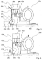
- FIG. 3 a third embodiment of a torque converter device of a motor vehicle is shown.
- an internal combustion engine and an electric motor 13c are permanently mechanically coupled to one another.
- An internal combustion engine output shaft 28c of the internal combustion engine and a rotor carrier 17c of the electric motor 13c are permanently mechanically connected to each other.
- the torque converter device has no disconnect clutch.
- the torque converter device has an integrally formed housing element 10c, which is provided for drivingly connecting a torque converter 23c and the internal combustion engine.
- the housing element 10c forms a plate carrier 14c designed as an outer plate carrier for holding a plurality of plates of a converter lockup clutch 15c.
- the plate carrier 14c picks up a disk pack.
- the housing element 10c also forms an actuating piston receptacle 20c, which forms an actuating piston 22c with a pressure chamber for actuating the torque converter lockup clutch 15c.
- the housing element 10c is designed as a cast component formed from light metal. It has aluminum and / or magnesium. In principle, the housing element 10c can also be designed as a sintered component.
- the torque converter device has a plug connection and a flexplate connection.
- the plug connection connects the housing element 10c and the rotor carrier 17c so as to transmit torque. It mechanically connects the housing element 10c and the rotor carrier 17c.
- the flexplate connection connects the housing element 10c and the internal combustion engine output shaft 28c to one another in a torque-transmitting manner. It mechanically interconnects the housing member 10c and the engine output shaft 28c.
- the flexplate connection has a flexplate 37c.
- the flexplate connection has a form-locking connection 38c and for the positive connection of the flexplate 37c to the housing element 10c a positive connection 39c.
- the positive-locking connections 38c, 39c each have at least one screw element which connects the housing element 10c in a form-fitting manner to the engine output shaft 28c.
- the interlocking connections 38c, 39c may additionally or alternatively have at least one rivet element.
- the housing element 10c For the positive connection of the housing element 10c with the flex plate 37c, and thus with the engine output shaft 28c, the housing element 10c forms a flexplate connection element 40c.
- the flexplate connecting member 40c and the housing member 10c are formed integrally with each other.
- the housing member 10c forms the flexplate connecting member 40c.
- the positive connection 39c connects the flexplate connecting element 40c in a form-fitting manner to the flexplate 37c.
- the Flexplattenanitatiselement 40c in this case has a two-part course.
- a first part of the flexplate connecting element 40c extends radially outwardly with respect to a rotation axis 32c, ie in a direction facing away from the rotation axis 32c, before a subsequent second part of the flexplate connection element 40c kinks and partially axially with respect to the rotation axis 32c in the direction of the internal combustion engine and partially radially runs outside.
- the flexplate connecting member 40c and the housing member 10c may be formed separately from each other, wherein they For example, by means of at least one screw permanently connected to each other mechanically.
- FIG. 4 a fourth embodiment of a torque converter device of a motor vehicle is shown.
- the torque converter device has an integrally formed housing element 10d, which is provided for drivingly connecting a torque converter 23d and the internal combustion engine.
- the housing element 10d forms a plate carrier 14d formed as an outer plate carrier for receiving a plurality of plates of a converter lockup clutch 15d.
- the plate carrier 14d receives a plate pack.
- the housing element 10d also forms an actuating piston receptacle 20d which, with an actuating piston 22d, forms a pressure chamber for actuating the torque converter lockup clutch 15d.
- the torque converter device has an electric motor 13d with a rotor carrier 17d.
- the housing member 10d is formed as a cast member formed of light metal. It has aluminum and / or magnesium. In principle, the housing element 10c can also be designed as a sintered component. In contrast to the previous embodiment according to FIG. 3 for the permanent mechanical connection of the housing element 10d to the internal combustion engine and thus to an internal combustion engine output shaft 28d, the torque converter device has a radial bearing 41d.
- the housing element 10d may additionally or alternatively be permanently mechanically connected via a mass flywheel to an internal combustion engine and thus to the internal combustion engine output shaft 28d.
- the mass flywheel is arranged with respect to a power flow between the engine and the housing member 10d.
- the mass flywheel connects the engine output shaft 28d of the internal combustion engine to the housing member 10d.
- the mass flywheel is designed as a dual mass flywheel.
- the mass flywheel has a primary flywheel fixedly connected to the engine output shaft 28d and a secondary flywheel fixedly connected to the housing member 10d.
- the two flywheel masses are connected to each other by means of a torsion damper.
- the housing element 10d can form the secondary flywheel mass of the mass flywheel, whereby the housing element 10d and the mass flywheel are partially formed integrally with one another.
- FIG. 5 a fifth embodiment of a torque converter device of a motor vehicle is shown.
- the motor vehicle is designed as a purely internal combustion engine operated motor vehicle.
- the motor vehicle has only one internal combustion engine for providing a drive torque. It has no electric motor which is provided for driving drive wheels of the motor vehicle.
- the torque converter device has an integrally formed housing element 10e, which is provided for drivingly connecting a torque converter 23e and the internal combustion engine.
- the housing element 10e forms a plate carrier 14e designed as an outer disk carrier for receiving a plurality of disks of a torque converter lockup clutch 15e.
- the plate carrier 14e receives a plate pack.
- the housing element 10e also forms an actuating piston receptacle 20e, which forms an actuating piston 22e with a pressure chamber for actuating the torque converter lockup clutch 15e.
- the housing element 10e is designed as a cast component formed from light metal. It has aluminum and / or magnesium. In principle, the housing element 10e can also be designed as a sintered component.
- the torque converter device For the mechanical connection of an internal combustion engine output shaft 28e of the internal combustion engine with the housing element 10e, the torque converter device has a flexplate connection.
- the flexplate connection connects the housing element 10e and the internal combustion engine output shaft 28e to one another in a torque-transmitting manner.
- the flexplate connection has a flexplate 37e.
- the flexplate connection For the positive connection of the flex plate 37e to the engine output shaft 28e, the flexplate connection has a form-locking connection 38e and for the form-fitting connection of the flexplate 37e to the housing element 10e a positive connection 39e.
- the positive-locking connections 38e, 39e each have at least one screw element which connects the housing element 10e in a form-fitting manner to the engine output shaft 28e.
- the interlocking connections 38e, 39e may additionally or alternatively have at least one rivet element.
- the housing element 10e For the positive connection of the housing element 10e with the flex plate 37e, and thus with the engine output shaft 28e, the housing element 10e forms a flexplate connection element 40e.
- the flexplate connection element 40e and the housing element 10e are integrally formed with one another.
- the form-fit connection 39e connects the flexplate connection element 40e in a form-fitting manner to the flexplate 37e.
- the Flexplattenanitatiselement 40e has a two-part course.
- a first part of the flexplate connecting element 40e extends radially outwardly with respect to a rotation axis 32e, ie in a direction facing away from the rotation axis 32e, before a subsequent second part of the flexplate connecting element 40e kinks and with respect to the rotation axis 32e partially axially in the direction of the internal combustion engine and partially radially runs outside.
- the torque converter apparatus includes an integrally formed housing member 10f provided to drive-connect a torque converter 23f and an internal combustion engine.
- the housing element 10f forms a disk carrier 14f designed as an outer disk carrier for receiving a plurality of disks of a torque converter lockup clutch 15f.
- the plate carrier 14f receives a plate pack.
- the housing element 10f also forms an actuation piston receptacle 20f which, with an actuation piston 22f, forms a pressure chamber for actuation of the lockup clutch 15f.
- the housing member 10f is formed as a cast member formed of light metal. It has aluminum and / or magnesium.
- the housing element 10e can also be designed as a sintered component.
- the torque converter device has a radial bearing 41d for the permanent mechanical connection of the housing element 10f to the internal combustion engine.
Landscapes
- Engineering & Computer Science (AREA)
- Mechanical Engineering (AREA)
- General Engineering & Computer Science (AREA)
- Chemical & Material Sciences (AREA)
- Combustion & Propulsion (AREA)
- Transportation (AREA)
- Hybrid Electric Vehicles (AREA)
Description
- Die Erfindung betrifft eine Drehmomentwandlervorrichtung nach dem Oberbegriff des Anspruchs 1.
- Aus der
US 2005/133328 A1 , derEP 0 308 072 A1 , derJP 2009 001127 A - Aus der gattungsgemäßen
DE 10 2009 042 050 A1 ist bereits eine Drehmomentwandlervorrichtung für ein Hybridkraftfahrzeug, mit einem einstückig ausgebildeten Gehäuseelement, das dazu vorgesehen ist, einen Drehmomentwandler und einen Verbrennungsmotor antriebstechnisch miteinander zu verbinden, bekannt. Dabei bildet das Gehäuseelement einen Lamellenträger zur Aufnahme von einer Lamelle einer Wandlerüberbrückungskupplung aus. - Der Erfindung liegt insbesondere die Aufgabe zugrunde, eine kostengünstige Drehmomentwandlervorrichtung bereitzustellen, die besonders einfach herstellbar ist. Diese Aufgabe wird gemäß der Erfindung durch die Merkmale des Anspruchs 1 gelöst. Weitere Ausgestaltungen ergeben sich aus den Unteransprüchen.
- Die Erfindung geht aus von einer Drehmomentwandlervorrichtung für ein Kraftfahrzeug, mit zumindest einem einstückig ausgebildeten Gehäuseelement, das dazu vorgesehen ist, einen Drehmomentwandler und einen Verbrennungsmotor antriebstechnisch miteinander zu verbinden.
- Dabei bildet das Gehäuseelement wenigstens einen Lamellenträger zur Aufnahme von zumindest einer Lamelle einer Wandlerüberbrückungskupplung aus. Dadurch kann ein vollintegrierter Lamellenträger bereitgestellt werden, wodurch die Drehmomentwandlervorrichtung vereinfacht werden kann. Weiter kann besonders einfach auf zumindest eine Verbindungsstelle verzichtet werden, wodurch eine Komplexität der Drehmomentwandlervorrichtung verringert, eine Montage vereinfacht und/oder Kosten, Gewicht und/oder ein benötigter Bauraum eingespart werden können. Besonders einfach kann dadurch eine Trägheit von Bauteilen der Drehmomentwandlervorrichtung reduziert werden, wodurch ein Wirkungsgrad der Drehmomentwandlervorrichtung erhöht werden kann. Dadurch kann eine kostengünstige Drehmomentwandlervorrichtung bereitgestellt werden, die besonders einfach herstellbar ist. Unter "einstückig" soll insbesondere eine Ausbildung als ein einziges Bauteil und/oder in einem einzigen Stück geformt verstanden werden. Unter einem Gehäuseelement" soll insbesondere ein Bauteil verstanden werden, das zumindest ein Bauteil der Drehmomentwandlervorrichtung umschließt und/oder zumindest im Wesentlichen einen Außenumfang und/oder eine axiale Erstreckung der Drehmomentwandlervorrichtung definiert. Unter einem "Lamellenträger" soll insbesondere ein Bauteil verstanden werden, das dazu vorgesehen ist, zumindest eine Lamelle einer Reibschlusskupplung drehfest und axial verschiebbar zu lagern. Vorzugsweise ist die Drehmomentwandlervorrichtung für ein Hybridkraftfahrzeug vorgesehen. Unter einer "Wandlerüberbrückungskupplung" soll insbesondere eine Kupplung verstanden werden, die dazu vorgesehen ist, in zumindest einem Betriebszustand einen Elektromotor und/oder den Verbrennungsmotor mit einer Getriebeeingangswelle mechanisch direkt zu verbinden. Unter "mechanisch direkt" soll in diesem Zusammenhang insbesondere verstanden werden, dass ein Drehmoment von dem Elektromotor und/oder von dem Verbrennungsmotor mechanisch auf die Getriebeeingangswelle übertragen wird und somit eine hydraulische Übertragung durch den Drehmomentwandler verhindert ist und der Drehmomentwandler dadurch umgangen wird. Unter "vorgesehen" soll insbesondere speziell ausgelegt, ausgestattet und/oder angeordnet verstanden werden.
- Dabei ist der Lamellenträger zur Aufnahme von zumindest einer Lamelle der Wandlerüberbrückungskupplung als ein Außenlamellenträger ausgebildet. Dadurch kann eine Montage weiter vereinfacht werden.
- In einer erfindungsgemäßen Ausgestaltung ist der Lamellenträger zur Aufnahme von einem Lamellenpaket vorgesehen. Dadurch kann eine besonders wirkungsvolle Wandlerüberbrückungskupplung bereitgestellt werden. Unter einem "Lamellenpaket" soll insbesondere eine Einheit verstanden werden, die zumindest zwei und vorteilhaft zumindest drei Lamellen umfasst.
- Ferner wird erfindungsgemäß vorgeschlagen, dass das Gehäuseelement zumindest eine Betätigungskolbenaufnahme ausbildet, die dazu vorgesehen ist, zumindest mit einem Betätigungskolben eine Druckkammer zur Betätigung der Wandlerüberbrückungskupplung auszubilden. Dadurch kann auf zumindest eine weitere Verbindungsstelle verzichtet werden und somit die Herstellung der Drehmomentwandlervorrichtung weiter vereinfacht und eine Trägheit weiter reduziert werden. Unter einer "Druckkammer" soll insbesondere eine hydraulisch und/oder pneumatisch beaufschlagbare Kammer verstanden werden, die zumindest eine feste Wand und zumindest eine bewegliche Wand umfasst. Unter einem "Betätigungskolben" soll insbesondere ein Bauteil verstanden werden, das dazu vorgesehen ist, vorzugsweise durch eine axiale Bewegung zumindest eine Lamelle einer Kupplung axial in dem Lamellenträger zu verschieben. Die Betätigungskolbenaufnahme ist vorzugsweise zur Führung des Betätigungskolbens vorgesehen.
- Erfindungsgemäß bildet das Gehäuseelement wenigstens einen Lamellenträger zur Aufnahme von zumindest einer Lamelle einer Trennkupplung, die dazu vorgesehen ist, in zumindest einem Betriebszustand einen Elektromotor und den Verbrennungsmotor mechanisch voneinander zu entkoppeln, aus. Durch die Ausbildung des Lamellenträgers der Trennkupplung und des Lamellenträgers der Wandlerüberbrückungskupplung durch das einstückig ausgebildete Gehäuseelement kann ein besonders vorteilhafter vollintegrierter Lamellenträger bereitgestellt werden, wodurch die Drehmomentwandlervorrichtung weiter vereinfacht werden kann. Das einstückig ausgebildete Gehäuseelement bildet vorzugsweise den Lamellenträger für die Wandlerüberbrückungskupplung und den Lamellenträger für die Trennkupplung aus. Der Lamellenträger für die Wandlerüberbrückungskupplung und der Lamellenträger für die Trennkupplung sind vorteilhafterweise durch ein und dasselbe Gehäuseelement ausgebildet und insbesondere verbindungsstellenfrei miteinander verbunden. Vorzugsweise ist der Lamellenträger zur Aufnahme von zumindest einer Lamelle der Trennkupplung als ein Außenlamellenträger ausgebildet. Der durch das Gehäuseelement ausgebildete Lamellenträger der Trennkupplung ist vorteilhafterweise zur Aufnahme von einem Lamellenpaket vorgesehen.
- Weiter ist es vorteilhaft, wenn das Gehäuseelement zumindest eine Betätigungskolbenaufnahme ausbildet, die dazu vorgesehen ist, zumindest mit einem Betätigungskolben eine Druckkammer zur Betätigung der Trennkupplung auszubilden. Dadurch kann auf zumindest eine weitere Verbindungsstelle verzichtet werden und somit die Herstellung der Drehmomentwandlervorrichtung weiter vereinfacht und eine Trägheit weiter reduziert werden. Das einstückig ausgebildete Gehäuseelement bildet vorzugsweise die Betätigungskolbenaufnahme für die Wandlerüberbrückungskupplung und die Betätigungskolbenaufnahme für die Trennkupplung aus. Die Betätigungskolbenaufnahme für die Wandlerüberbrückungskupplung und die Betätigungskolbenaufnahme für die Trennkupplung sind vorteilhafterweise durch ein und dasselbe Gehäuseelement ausgebildet und insbesondere verbindungsstellenfrei miteinander verbunden.
- Weiter wird vorgeschlagen, dass die Drehmomentwandlervorrichtung zumindest einen Drehmomentwandler mit einem Pumpenrad und zumindest eine Formschlussverbindung, die dazu vorgesehen ist, das Pumpenrad und das Gehäuseelement formschlüssig miteinander zu verbinden, aufweist. Dadurch kann eine besonders vorteilhafte Drehmomentwandlervorrichtung bereitgestellt werden.
- Ferner wird vorgeschlagen, dass die Formschlussverbindung zumindest ein Schraubelement und/oder ein Nietelement aufweist. Dadurch können das Pumpenrad und das Gehäuseelement besonders einfach miteinander verbunden werden.
- In einer vorteilhaften Ausgestaltung weist die Drehmomentwandlervorrichtung einen Rotorträger und eine Steckverbindung auf, die das Gehäuseelement und den Rotorträger drehmomentübertragend miteinander verbindet. Dadurch kann eine besonders vorteilhafte Drehmomentwandlervorrichtung bereitgestellt werden. Außerdem kann dadurch der Elektromotor besonders einfach zentriert werden. Unter einem "Rotorträger" soll insbesondere ein Bauteil verstanden werden, das permanent drehfest mit einem Rotor des Elektromotors verbunden ist und somit eine gleiche Drehzahl wie der Rotor ausweist.
- Weiter wird vorgeschlagen, dass das Gehäuseelement als ein Guss- und/oder Sinterbauteil ausgebildet ist. Dadurch kann besonders einfach das Gehäuseelement als ein einstückiges Bauteil, insbesondere in einem Arbeitsschritt, ausgebildet werden, wodurch sich eine Herstellung der Drehmomentwandlervorrichtung weiter vereinfachen kann. Unter einem "Gussbauteil" soll insbesondere ein aus einem Guss und/oder ein mittels Gießen hergestelltes festes Bauteil verstanden werden. Vorzugsweise ist eine Form des festen Gussbauteils zumindest im Wesentlichen durch einen Gussvorgang bestimmt, wobei die Form des festen Gussbauteils mittels einer spanenden Bearbeitung angepasst werden kann, wie beispielsweise durch Bohren, Fräsen, Drehen, Schleifen und/oder Ähnliches. Unter einem "Sinterbauteil" soll insbesondere ein mittels Sintern hergestelltes festes Bauteil verstanden werden. Vorzugsweise ist eine Form des festen Sinterbauteils zumindest im Wesentlichen durch einen Sintervorgang bestimmt, wobei die Form des festen Sinterbauteils mittels einer spanenden Bearbeitung angepasst werden kann, wie beispielsweise durch Bohren, Fräsen, Drehen, Schleifen und/oder Ähnliches. Vorteilhafterweise kann das feste Gussbauteil und/oder das feste Sinterbauteil ein Vollmaterial ausbilden, aus dem das Gehäuseelement, insbesondere durch eine spanende Bearbeitung, hergestellt ist. Vorzugsweise ist die Form des festen Gussbauteils und des festen Sinterbauteils mittels eines Verfahrens bestimmt, das von einem Umformverfahren abweicht. Das Gussbauteil und/oder Sinterbauteil ist insbesondere nicht als Blechbauteil, insbesondere nicht als Blechumformbauteil ausgebildet.
- Ferner wird vorgeschlagen, dass das Gehäuseelement zumindest im Wesentlichen aus Leichtmetall ausgebildet ist. Dadurch kann ein Gewicht der Drehmomentwandlervorrichtung besonders einfach reduziert werden. Unter "aus Leichtmetall ausgebildet" soll insbesondere verstanden werden, dass das Gehäuseelement aus einem Leichtmetall gegossen und/oder gesintert ist, wobei auch Legierungen denkbar sind. Unter "zumindest im Wesentlichen" soll insbesondere verstanden werden, dass das Gehäuseelement entweder vollständig aus Leichtmetall oder im Wesentlichen aus Leichtmetall ausgebildet ist. Unter "im Wesentlichen" soll insbesondere verstanden werden, dass das Gehäuseelement mindestens zu 80%, vorteilhaft mindestens zu 90% und besonders vorteilhaft mindestens zu 95% aus Leichtmetall ausgebildet ist.
- In einer besonders vorteilhaften Ausgestaltung weist das Gehäuseelement Aluminium und/oder Magnesium auf. Dadurch kann ein besonders vorteilhaftes Material zur Ausbildung des Gehäuseelements verwendet werden. Unter aufweisen" soll in diesem Zusammenhang insbesondere verstanden werden, dass das Gehäuseelement aus Aluminium oder aus Magnesium oder aus einer Legierung von Aluminium und Magnesium ausgebildet ist.
- Weitere Vorteile ergeben sich aus der folgenden Zeichnungsbeschreibung. In den Zeichnungen sind sechs Ausführungsbeispiele dargestellt. Die Zeichnungen, die Beschreibung und die Ansprüche enthalten zahlreiche Merkmale in Kombination. Der Fachmann wird die Merkmale zweckmäßigerweise auch einzeln betrachten und zu sinnvollen weiteren Kombinationen zusammenfassen.
- Dabei zeigen:
- Fig. 1
- schematisch eine erfindungsgemäße Drehmomentwandlervorrichtung für ein Hybridkraftfahrzeug,
- Fig. 2
- eine alternativ ausgebildete erfindungsgemäße Drehmomentwandlervorrichtung für ein Hybridkraftfahrzeug schematisiert dargestellt,
- Fig. 3
- ein drittes Ausführungsbeispiel einer Drehmomentwandlervorrichtung für ein Hybridkraftfahrzeug, das nicht beansprucht wird,
- Fig. 4
- ein viertes Ausführungsbeispiel einer Drehmomentwandlervorrichtung für ein Hybridkraftfahrzeug, das nicht beansprucht wird,
- Fig. 5
- ein fünftes Ausführungsbeispiel einer Drehmomentwandlervorrichtung für ein Kraftfahrzeug, das nicht beansprucht wird, und
- Fig. 6
- ein sechstes Ausführungsbeispiel einer Drehmomentwandlervorrichtung für ein Kraftfahrzeug, das nicht beansprucht wird.
- Die
Figur 1 zeigt schematisch eine erfindungsgemäße Drehmomentwandlervorrichtung eines Kraftfahrzeugs. Die Drehmomentwandlervorrichtung ist als eine hydraulische Drehmomentwandlervorrichtung ausgebildet. Zur Bereitstellung eines Antriebsmoments weist das Kraftfahrzeug einen Elektromotor 13a und einen nicht näher dargestellten Verbrennungsmotor auf, die entweder einzeln oder in Kombination Antriebsräder des Kraftfahrzeugs antreiben. Der Elektromotor 13a und der Verbrennungsmotor sind bezüglich eines Kraftflusses vor der Drehmomentwandlervorrichtung angeordnet. Zur Anbindung an die Drehmomentwandlervorrichtung weist der Elektromotor 13a einen Rotor 18a und der Verbrennungsmotor eine Verbrennungsmotorausgangswelle 28a auf. Zur Bereitstellung von mehreren Getriebegängen weist die Drehmomentwandlervorrichtung ein nicht näher dargestelltes Getriebe auf, das in dem Kraftfluss hinter der Drehmomentwandlervorrichtung angeordnet ist. Das Getriebe weist zur Anbindung an die Drehmomentwandlervorrichtung eine Getriebeeingangswelle 16a auf. Die Verbrennungsmotorausgangswelle 28a ist als eine Kurbelwelle des Verbrennungsmotors ausgebildet. Das Kraftfahrzeug ist als ein Hybridkraftfahrzeug ausgebildet. - Die Drehmomentwandlervorrichtung weist weiter einen hydraulischen Drehmomentwandler 23a auf. Der Drehmomentwandler 23a ist als ein Anfahrelement ausgebildet. Er weist ein Pumpenrad 24a, ein Turbinenrad 29a und ein Leitrad 30a auf. Das Pumpenrad 24a ist permanent mit dem Rotor 18a des Elektromotors 13a verbunden und mit der Verbrennungsmotorausgangswelle 28a verbindbar. Das Turbinenrad 29a ist über einen Schwingungsdämpfer 31a permanent mit der Getriebeeingangswelle 16a verbunden.
- Die Drehmomentwandlervorrichtung weist ferner eine Trennkupplung 12a auf, die dazu vorgesehen ist, in einem Betriebszustand den Elektromotor 13a und den Verbrennungsmotor mechanisch voneinander zu entkoppeln und in einem anderen Betriebszustand den Elektromotor 13a und den Verbrennungsmotor mechanisch miteinander zu koppeln. Die Trennkupplung 12a ist zur mechanischen Anbindung und zur mechanischen Trennung des Verbrennungsmotors an die bzw. von der Drehmomentwandlervorrichtung vorgesehen. Die Trennkupplung 12a ist zur mechanischen Kopplung dazu vorgesehen, die Verbrennungsmotorausgangswelle 28a mechanisch mit dem Rotor 18a zu verbinden und zur mechanischen Entkopplung die Verbrennungsmotorausgangswelle 28a mechanisch von dem Rotor 18a zu trennen. Die Trennkupplung 12a ist als eine Lamellenkupplung ausgebildet. Sie weist zur Verbindung der Verbrennungsmotorausgangswelle 28a mit dem Rotor 18a zwei Lamellenpakete auf. Jeweils ein Lamellenpaket umfasst mehrere Lamellen, die nebeneinander angeordnet sind. Die zwei Lamellenpakete greifen teilweise ineinander. Ein Lamellenpaket ist drehfest mit dem Rotor 18a und das andere Lamellenpaket drehfest mit der Verbrennungsmotorausgangswelle 28a verbunden. Das drehfest mit dem Rotor 18a verbundene Lamellenpaket ist als ein äußeres Lamellenpaket ausgebildet. Das drehfest mit der Verbrennungsmotorausgangswelle 28a verbundene Lamellenpaket ist als ein inneres Lamellenpaket ausgebildet. Grundsätzlich kann die Trennkupplung 12a auch nur eine Lamelle aufweisen.
- Zur mechanisch direkten Verbindung des Elektromotors 13a und/oder des Verbrennungsmotors mit der Getriebeeingangswelle 16a weist die Drehmomentwandlervorrichtung eine Wandlerüberbrückungskupplung 15a auf. In einem anderen Betriebszustand ist die Wandlerüberbrückungskupplung 15a dazu vorgesehen, den Elektromotor 13a und/oder den Verbrennungsmotor mit der Getriebeeingangswelle 16a über den Drehmomentwandler 23a zu verbinden. Die Wandlerüberbrückungskupplung 15a ist zur Umgehung des Drehmomentwandlers 23a vorgesehen. Sie ist dazu vorgesehen, den Drehmomentwandler 23a in unwirtschaftlichen Betriebspunkten zu überbrücken. Die Wandlerüberbrückungskupplung 15a ist zur mechanischen Anbindung, d.h. über den Schwingungsdämpfer 31a, und zur hydraulischen Anbindung, d.h. über den Drehmomentwandler 23a, des Elektromotors 13a und/oder des Verbrennungsmotors an die Getriebeeingangswelle 16a vorgesehen. Sie ist dazu vorgesehen, zur mechanischen Anbindung den Rotor 18a mit der Getriebeeingangswelle 16a über den Schwingungsdämpfer 31a zu verbinden und zur hydraulischen Anbindung den Rotor 18a mit der Getriebeeingangswelle 16a über den Drehmomentwandler 23a zu verbinden. Die Wandlerüberbrückungskupplung 15a ist als eine Lamellenkupplung ausgebildet. Sie weist zur Anbindung des Rotors 18a an den Schwingungsdämpfer 31a zwei Lamellenpakete auf. Jeweils ein Lamellenpaket umfasst mehrere Lamellen, die nebeneinander angeordnet sind. Die zwei Lamellenpakete greifen teilweise ineinander. Ein Lamellenpaket ist drehfest mit dem Rotor 18a und das andere Lamellenpaket drehfest mit einem Eingang des Schwingungsdämpfers 31a verbunden. Das drehfest mit dem Rotor 18a verbundene Lamellenpaket ist als ein äußeres Lamellenpaket ausgebildet. Das drehfest mit dem Eingang des Schwingungsdämpfers 31a verbundene Lamellenpaket ist als ein inneres Lamellenpaket ausgebildet. Grundsätzlich kann die Wandlerüberbrückungskupplung 15a auch nur eine Lamelle aufweisen.
- Zur Lagerung der Lamellenpakete der Trennkupplung 12a weist die Drehmomentwandlervorrichtung einen Lamellenträger 11 a und einen Lamellenträger 35a auf. Der Lamellenträger 11 a, der zur Aufnahme der Lamellen der Trennkupplung 12a vorgesehen ist, ist als ein Außenlamellenträger ausgebildet. Der Lamellenträger 35a ist als ein Innenlamellenträger ausgebildet. Der Lamellenträger 11a lagert axial beweglich die Lamellen des Lamellenpakets der Trennkupplung 12a, die drehfest mit dem Rotor 18a verbunden sind. Er lagert Außenlamellen der Trennkupplung 12a. Der Lamellenträger 35a lagert axial beweglich die Lamellen des Lamellenpakets der Trennkupplung 12a, die drehfest mit der Verbrennungsmotorausgangswelle 28a verbunden sind. Er lagert Innenlamellen der Trennkupplung 12a.
- Zur Lagerung der Lamellenpakete der Wandlerüberbrückungskupplung 15a weist die Drehmomentwandlervorrichtung einen Lamellenträger 14a und einen Lamellenträger 36a auf. Der Lamellenträger 14a, der zur Aufnahme der Lamellen der Wandlerüberbrückungskupplung 15a vorgesehen ist, ist als ein Außenlamellenträger ausgebildet. Der Lamellenträger 36a ist als ein Innenlamellenträger ausgebildet. Der Lamellenträger 14a lagert axial beweglich die Lamellen des Lamellenpakets der Wandlerüberbrückungskupplung 15a, die drehfest mit dem Rotor 18a verbunden sind. Er lagert Außenlamellen der Wandlerüberbrückungskupplung 15a. Der Lamellenträger 36a lagert axial beweglich die Lamellen des Lamellenpakets der Wandlerüberbrückungskupplung 15a, die drehfest mit dem Eingang des Schwingungsdämpfers 31a verbunden sind. Er lagert Innenlamellen der Wandlerüberbrückungskupplung 15a.
- Zur Ausbildung des Lamellenträgers 11a für die Trennkupplung 12a und des Lamellenträgers 14a für die Wandlerüberbrückungskupplung 15a weist die Drehmomentwandlervorrichtung ein einstückig ausgebildetes Gehäuseelement 10a auf. Das Gehäuseelement 10a ist dazu vorgesehen, den Drehmomentwandler 23a und den Verbrennungsmotor antriebstechnisch miteinander zu verbinden. Das Gehäuseelement 10a bildet den Lamellenträger 11a und den Lamellenträger 14a aus. Die Lamellenträger 11a, 14a sind durch das Gehäuseelement 10a einstückig miteinander ausgebildet. Die Lamellenträger 35a, 36a sind innerhalb des die Lamellenträger 11a, 14a ausbildenden Gehäuseelements 10a angeordnet.
- Das einstückige Gehäuseelement 10a bildet den Lamellenträger 11a, der zur Aufnahme von dem äußeren Lamellenpaket der Trennkupplung 12a vorgesehen ist, und den Lamellenträger 14a, der zur Aufnahme von dem äußeren Lamellenpaket der Wandlerüberbrückungskupplung 15a vorgesehen ist. Das Gehäuseelement 10a nimmt die Lamellenpakete der Trennkupplung 12a und der Wandlerüberbrückungskupplung 15a axial beweglich, d.h. entlang einer Rotationsachse 32a der Drehmomentwandlervorrichtung beweglich auf, die drehfest mit dem Rotor 18a des Elektromotors 13a verbunden sind. Das einstückig ausgebildete Gehäuseelement 10a bildet einen Außenlamellenträger der Trennkupplung 12a und einen Außenlamellenträger der Wandlerüberbrückungskupplung 15a aus. Das äußere Lamellenpaket der Trennkupplung 12a und das äußere Lamellenpaket der Wandlerüberbrückungskupplung 15a sind auf dem gemeinsamen Gehäuseelement 10a drehfest angeordnet. Grundsätzlich kann der Lamellenträger 11 a und/oder der Lamellenträger 14a lediglich zur Aufnahme von einer Lamelle vorgesehen sein.
- Zur Aufnahme des Rotors 18a weist die Drehmomentwandlervorrichtung einen Rotorträger 17a auf. Der Rotorträger 17a trägt den Rotor 18a des Elektromotors 13a. Zur drehmomentübertragenden Verbindung des Gehäuseelements 10a und des Rotorträgers 17a weist die Drehmomentwandlervorrichtung eine Steckverbindung auf. Das einstückige Gehäuseelement 10a und der Rotorträger 17a sind mittels der Steckverbindung permanent drehfest miteinander verbunden. Damit sind die Lamellenträger 11a, 14a mittels der Steckverbindung permanent drehfest mit dem Rotor 18a verbunden. Der Rotorträger 17a ist aus Stahl ausgebildet. Grundsätzlich kann das Gehäuseelement 10a aber auch zumindest teilweise den Rotorträger 17a ausbilden, wodurch der Rotorträger 17a und das Gehäuseelement 10a zumindest teilweise einstückig miteinander ausgebildet sind.
- Zur Betätigung der Wandlerüberbrückungskupplung 15a weist die Drehmomentwandlervorrichtung eine Betätigungskolbenaufnahme 20a auf. Das einstückig ausgebildete Gehäuseelement 10a bildet die Betätigungskolbenaufnahme 20a zur Betätigung der Wandlerüberbrückungskupplung 15a aus. Die durch das Gehäuseelement 10a ausgebildete Betätigungskolbenaufnahme 20a bildet zur Betätigung der Wandlerüberbrückungskupplung 15a mit einem Betätigungskolben 22a der Drehmomentwandlervorrichtung eine hydraulische Druckkammer aus. Das Gehäuseelement 10a bildet somit eine Betätigungskolbenführung aus. Die Betätigungskolbenaufnahme 20a weist eine Trennwand auf. Die Trennwand der Betätigungskolbenaufnahme 20a ist einstückig mit dem Gehäuseelement 10a ausgebildet. Das Gehäuseelement 10a bildet somit zusätzlich zu den Lamellenträgern 11a, 14a auch die Trennwand der Betätigungskolbenaufnahme 20a aus. Die Lamellenträger 11a, 14a und die Trennwand der Betätigungskolbenaufnahme 20a sind durch das Gehäuseelement 10a einstückig miteinander ausgebildet. Die Trennwand der Betätigungskolbenaufnahme 20a ist als eine feste Wand der durch die Betätigungskolbenaufnahme 20a und den Betätigungskolben 22a ausgebildeten Druckkammer ausgebildet.
- Der Betätigungskolben 22a bildet eine bewegliche Wand der durch die Betätigungskolbenaufnahme 20a und den Betätigungskolben 22a ausgebildeten Druckkammer aus. Durch eine Beaufschlagung der durch die Betätigungskolbenaufnahme 20a und den Betätigungskolben 22a gebildeten Druckkammer mit einem Betriebsmittel entsteht eine axiale Betätigungskraft, die den Betätigungskolben 22a in eine axiale Betätigungsrichtung 34a verschiebt, wodurch der Betätigungskolben 22a eine Lamelle des äußeren Lamellenpakets der Wandlerüberbrückungskupplung 15a in die Betätigungsrichtung 34a axial schiebt und die Lamellen der beiden Lamellenpakete der Wandlerüberbrückungskupplung 15a gegeneinander drückt. Dadurch ist die Wandlerüberbrückungskupplung 15a geschlossen und der Drehmomentwandler 23a wird umgangen. Das Betriebsmittel ist als Öl ausgebildet.
- Zur Betätigung der Trennkupplung 12a weist die Drehmomentwandlervorrichtung eine Betätigungskolbenaufnahme 19a auf. Der Rotorträger 17a bildet die Betätigungskolbenaufnahme 19a zur Betätigung der Trennkupplung 12a aus. Die Betätigungskolbenaufnahme 19a bildet zur Betätigung der Trennkupplung 12a mit einem Betätigungskolben 21 a der Drehmomentwandlervorrichtung eine hydraulische Druckkammer aus. Die Betätigungskolbenaufnahme 19a weist eine Trennwand auf. Die Trennwand der Betätigungskolbenaufnahme 19a ist einstückig mit dem Rotorträger 17a ausgebildet. Der Rotorträger 17a bildet somit die Trennwand der Betätigungskolbenaufnahme 19a aus. Die Trennwand der Betätigungskolbenaufnahme 19a ist als eine feste Wand der durch die Betätigungskolbenaufnahme 19a und den Betätigungskolben 21a ausgebildeten Druckkammer ausgebildet. Der Betätigungskolben 21a bildet eine bewegliche Wand der durch die Betätigungskolbenaufnahme 19a und den Betätigungskolben 21a ausgebildeten Druckkammer aus. Durch eine Beaufschlagung der durch die Betätigungskolbenaufnahme 19a und den Betätigungskolben 21 a gebildeten Druckkammer mit einem Betriebsmittel entsteht eine axiale Betätigungskraft, die den Betätigungskolben 21a in eine axiale Betätigungsrichtung 33a verschiebt, wodurch der Betätigungskolben 21a eine Lamelle des äußeren Lamellenpakets der Trennkupplung 12a in die Betätigungsrichtung 33a axial schiebt und die Lamellen der beiden Lamellenpakete der Trennkupplung 12a gegeneinander drückt. Dadurch ist die Trennkupplung 12a geschlossen und die Verbrennungsmotorausgangswelle 28a mit dem Rotor 18a verbunden.
- Die Betätigungskolbenaufnahme 19a ist dazu vorgesehen, die axiale Betätigungsrichtung 33a, in die der Betätigungskolben 21 a zur Schaltung der Trennkupplung 12a bewegt wird, bereitzustellen. Die Betätigungskolbenaufnahme 20a ist dazu vorgesehen, die axiale Betätigungsrichtung 34a, in die der Betätigungskolben 22a zur Schaltung der Wandlerüberbrückungskupplung 15a bewegt wird, bereitzustellen. In diesem Ausführungsbeispiel sind die Betätigungsrichtungen 33a, 34a gleich ausgerichtet. Sie zeigen in die gleiche Richtung und sind parallel zueinander orientiert. Die beiden Betätigungsrichtungen 33a, 34a zeigen jeweils in Richtung Drehmomentwandler 23a. Die Betätigungskolben 21a, 22a sind somit jeweils dem Drehmomentwandler 23a zugewandt, wobei der Betätigungskolben 21 a dem Betätigungskolben 22a zugewandt und der Betätigungskolben 22a dem Betätigungskolben 21 a abgewandt ist.
- Entlang der Rotationsachse 32a ist die Betätigungskolbenaufnahme 19a vor der Trennkupplung 12a angeordnet. Die Betätigungskolbenaufnahme 20a ist entlang der Rotationsachse 32a hinter der Trennkupplung 12a und vor der Wandlerüberbrückungskupplung 15a angeordnet. Sie ist entlang der Rotationsachse 32a zwischen der Trennkupplung 12a und der Wandlerüberbrückungskupplung 15a angeordnet.
- Das Gehäuseelement 10a bildet also die Lamellenträger 11 a, 14a und die Betätigungskolbenaufnahme 20a aus. Die Lamellenträger 11a, 14a und die Betätigungskolbenaufnahme 20a sind einstückig miteinander ausgebildet. Sie sind verbindungsstellenfrei, d.h. ohne eine Verbindungsstelle miteinander verbunden. Die Trennwand der Betätigungskolbenaufnahme 19a und die Trennwand der Betätigungskolbenaufnahme 20a sind separat voneinander ausgebildet. Sie sind beabstandet zueinander angeordnet. Die Trennwand der Betätigungskolbenaufnahme 20a ist dabei entlang der Rotationsachse 32a zwischen der Trennkupplung 12a und der Wandlerüberbrückungskupplung 15a angeordnet.
- Zur permanenten Verbindung des Gehäuseelements 10a und damit des Rotors 18a mit dem Pumpenrad 24a weist die Drehmomentwandlervorrichtung eine einzige Formschlussverbindung 25a auf, die das Pumpenrad 24a und das Gehäuseelement 10a formschlüssig miteinander verbindet. Die Formschlussverbindung 25a verbindet das Pumpenrad 24a damit formschlüssig mit dem Lamellenträger 11a, mit dem Lamellenträger 14a, mit der Betätigungskolbenaufnahme 19a, mit der Betätigungskolbenaufnahme 20a und mit dem Rotorträger 17a. Die Drehmomentwandlervorrichtung weist zur Verbindung der beiden Lamellenträger 11 a, 14a, der beiden Betätigungskolbenaufnahmen 19a, 20a und des Rotorträgers 17a mit dem Pumpenrad 24a lediglich eine als die Formschlussverbindung 25a ausgebildete Verbindungsstelle und eine als die Steckverbindung ausgebildete Verbindungsstelle auf. Zur Verbindung der beiden Lamellenträger 11a, 14a und der Betätigungskolbenaufnahme 20a mit dem Pumpenrad 24a weist die Drehmomentwandlervorrichtung lediglich eine einzige als die Formschlussverbindung 25a ausgebildete Verbindungsstelle auf. Das Gehäuseelement 10a und das Pumpenrad 24a sind formschlüssig miteinander verbunden. Zur formschlüssigen Verbindung des Gehäuseelements 10a und des Pumpenrads 24a weist die Formschlussverbindung 25a ein Schraubelement 26a auf. Das Gehäuseelement 10a und das Pumpenrad 24a sind somit mittels des Schraubelements 26a formschlüssig miteinander verbunden. Sie sind verschraubt miteinander.
- Zur einstückigen Ausbildung ist das Gehäuseelement 10a als ein Gussbauteil ausgebildet. Das Gehäuseelement 10a ist in einem Stück gegossen. Es wird zur Herstellung gegossen. Die beiden Lamellenträger 11a, 14a und die Betätigungskolbenaufnahme 20a bzw. die Trennwand der Betätigungskolbenaufnahme 20a sind durch das Gussbauteil ausgebildet. Sie sind durch einen Gießvorgang ausgebildet. Grundsätzlich kann das Gehäuseelement 10a auch als ein Sinterbauteil ausgebildet sein.
- Zur Reduzierung eines Gewichts ist das Gehäuseelement 10a aus Leichtmetall ausgebildet. Die Lamellenträger 11a, 14a und die Betätigungskolbenaufnahme 20a bzw. die Trennwand der Betätigungskolbenaufnahme 20a sind aus Leichtmetall. In diesem Ausführungsbeispiel weisen das Gehäuseelement 10a und damit die Lamellenträger 11a, 14a und die Betätigungskolbenaufnahme 20a Aluminium auf. Das Gehäuseelement 10a ist aus Aluminium gegossen. Das Gehäuseelement 10a ist als ein Aluminiumgussteil ausgebildet. Somit sind die Lamellenträger 11a, 14a und die Betätigungskolbenaufnahme 20a aus Aluminium gegossen und damit als ein und dasselbe Aluminiumgussteil ausgebildet. Grundsätzlich kann das Gehäuseelement 10a alternativ oder zusätzlich Magnesium aufweisen. Es kann grundsätzlich als ein Magnesiumgussteil oder als ein Aluminium-Magnesium-Gussteil ausgebildet sein.
- In den
Figuren 2 bis 6 sind fünf weitere Ausführungsbeispiele gezeigt. Die nachfolgende Beschreibung beschränkt sich im Wesentlichen auf die Unterschiede zwischen den Ausführungsbeispielen, wobei bezüglich gleich bleibender Bauteile, Merkmale und Funktionen auf die Beschreibung des anderen Ausführungsbeispiels, insbesondere derFigur 1 , verwiesen werden kann. Zur Unterscheidung der Ausführungsbeispiele ist der Buchstabe a in den Bezugszeichen des Ausführungsbeispiels in derFigur 1 durch die Buchstaben b, c, d, e und f in den Bezugszeichen der Ausführungsbeispiele in denFiguren 2 bis 6 ersetzt. Bezüglich gleich bezeichneter Bauteile, insbesondere in Bezug auf Bauteile mit gleichen Bezugszeichen, kann grundsätzlich auch auf die Zeichnung und/oder die Beschreibung des Ausführungsbeispiels derFigur 1 verwiesen werden. - In der
Figur 2 ist eine alternativ ausgebildete erfindungsgemäße Drehmomentwandlervorrichtung eines Kraftfahrzeugs, mit zumindest einem einstückig ausgebildeten Gehäuseelement 10b, das einen Lamellenträger 11 b zur Aufnahme von mehreren Lamellen einer Trennkupplung 12b, einen Lamellenträger 14b zur Aufnahme von mehreren Lamellen einer Wandlerüberbrückungskupplung 15b und eine Betätigungskolbenaufnahme 20b zur Aufnahme eines Betätigungskolbens 22b ausbildet. Weiter weist die Drehmomentwandlervorrichtung einen Rotorträger 17b zur Aufnahme eines Rotors 18b eines Elektromotors 13b und einen Drehmomentwandler 23b auf, dessen Pumpenrad 24b mittels einer Formschlussverbindung 25b mit dem Gehäuseelement 10b und dessen Turbinenrad 29b mit einer Getriebeeingangswelle 16b verbunden ist. - Im Unterschied zu dem vorherigen Ausführungsbeispiel weist die Formschlussverbindung 25b zur formschlüssigen Verbindung des Pumpenrads 24b mit dem Gehäuseelement 10b ein Nietelement 27b auf. Das Gehäuseelement 10b und das Pumpenrad 24b sind somit mittels des Nietelements 27b formschlüssig miteinander verbunden, wobei über das Nietelement 27b zusätzlich zur formschlüssigen Verbindung auch eine kraftschlüssige Verbindung hergestellt wird. Sie sind miteinander vernietet. Das Nietelement 27b ist zusätzlich verschweißt. Das Gehäuseelement 10b und das Pumpenrad 24b sind damit mittels eines Schweißniets formschlüssig miteinander verbunden.
- Weiter bildet das Gehäuseelement 10b im Unterschied zu dem vorhergehenden Ausführungsbeispiel die Betätigungskolbenaufnahme 20b zur Aufnahme des Betätigungskolbens 22b und eine Betätigungskolbenaufnahme 19b zur Aufnahme eines Betätigungskolbens 21 b aus. Die Betätigungskolbenaufnahme 19b und die Betätigungskolbenaufnahme 20b weisen eine gemeinsame Trennwand auf. Die gemeinsame Trennwand der Betätigungskolbenaufnahmen 19b, 20b ist dabei entlang einer Rotationsachse 32b zwischen der Trennkupplung 12b und der Wandlerüberbrückungskupplung 15b angeordnet. Sie ist als eine feste Wand einer durch die Betätigungskolbenaufnahme 19b und den Betätigungskolben 21b ausgebildeten Druckkammer und als eine feste Wand einer durch die Betätigungskolbenaufnahme 20b und den Betätigungskolben 22b ausgebildeten Druckkammer ausgebildet.
- In diesem Ausführungsbeispiel stellen die Betätigungskolbenaufnahmen 19b, 20b jeweils eine Betätigungsrichtung 33b, 34b bereit, die entgegengesetzt zueinander ausgerichtet sind. Sie zeigen in entgegengesetzte Richtungen und sind parallel zueinander orientiert. Die beiden Betätigungsrichtungen 33b, 34b sind einander abgewandt. Die Betätigungsrichtung 33b der Betätigungskolbenaufnahme 19b zeigt weg von dem Drehmomentwandler 23b und ist diesem abgewandt. Die Betätigungsrichtung 34b der Betätigungskolbenaufnahme 20b zeigt in Richtung Drehmomentwandler 23b und ist diesem zugewandt. Der Betätigungskolben 21 b ist somit dem Drehmomentwandler 23b abgewandt und der Betätigungskolben 22b dem Drehmomentwandler 23b zugewandt. Die Betätigungskolben 21 b, 22b sind einander abgewandt. Entlang der Rotationsachse 32b sind die Betätigungskolbenaufnahmen 19b, 20b beide zwischen der Trennkupplung 12b und der Wandlerüberbrückungskupplung 15b angeordnet.
- Zur einstückigen Ausbildung ist das Gehäuseelement 10b im Unterschied zu dem vorhergehenden Ausführungsbeispiel als ein Sinterbauteil ausgebildet. Das Gehäuseelement 10b ist in einem Stück gesintert. Es wird zur Herstellung gesintert. Die beiden Lamellenträger 11 b, 14b und die beiden Betätigungskolbenaufnahmen 19b, 20b, und damit die Trennwände, sind durch das Sinterbauteil ausgebildet. Sie sind durch einen Sintervorgang ausgebildet. Grundsätzlich kann das Gehäuseelement 10b auch als ein Gussbauteil ausgebildet sein.
- Im Unterschied zu dem vorhergehenden Ausführungsbeispiel weisen das Gehäuseelement 10b und damit die Lamellenträger 11 b, 14b und die Betätigungskolbenaufnahmen 19b, 20b Magnesium auf. Das Gehäuseelement 10b ist aus Magnesium gesintert. Das Gehäuseelement 10b ist als ein Magnesiumsinterteil ausgebildet. Somit sind die Lamellenträger 11b, 14b und die Betätigungskolbenaufnahmen 19b, 20b aus Magnesium gesintert und damit als ein und dasselbe Magnesiumsinterteil ausgebildet. Grundsätzlich kann das Gehäuseelement 10b alternativ oder zusätzlich Aluminium aufweisen. Es kann grundsätzlich als ein Aluminium-Sinterteil oder als ein Aluminium-Magnesium-Sinterteil ausgebildet sein.
- In der
Figur 3 ist ein drittes Ausführungsbeispiel einer Drehmomentwandlervorrichtung eines Kraftfahrzeugs dargestellt. Im Unterschied zu den vorherigen Ausführungsbeispielen sind ein Verbrennungsmotor und ein Elektromotor 13c permanent mechanisch miteinander gekoppelt. Eine Verbrennungsmotorausgangswelle 28c des Verbrennungsmotors und ein Rotorträger 17c des Elektromotors 13c sind permanent mechanisch miteinander verbunden. Die Drehmomentwandlervorrichtung weist keine Trennkupplung auf. - Die Drehmomentwandlervorrichtung weist ein einstückig ausgebildetes Gehäuseelement 10c auf, das dazu vorgesehen ist, einen Drehmomentwandler 23c und den Verbrennungsmotor antriebstechnisch miteinander zu verbinden. Das Gehäuseelement 10c bildet einen als ein Außenlamellenträger ausgebildeten Lamellenträger 14c zur Aufnahme von mehreren Lamellen einer Wandlerüberbrückungskupplung 15c aus. Der Lamellenträger 14c nimmt ein Lamellenpaket auf. Das Gehäuseelement 10c bildet zudem eine Betätigungskolbenaufnahme 20c aus, die mit einem Betätigungskolben 22c eine Druckkammer zur Betätigung der Wandlerüberbrückungskupplung 15c ausbildet. Das Gehäuseelement 10c ist als ein aus Leichtmetall gebildetes Gussbauteil ausgebildet. Es weist Aluminium und/oder Magnesium auf. Grundsätzlich kann das Gehäuseelement 10c auch als ein Sinterbauteil ausgebildet sein.
- Zur mechanischen Verbindung der Verbrennungsmotorausgangswelle 28c mit dem Rotorträger 17c weist die Drehmomentwandlervorrichtung eine Steckverbindung und eine Flexplattenanbindung auf. Die Steckverbindung verbindet das Gehäuseelement 10c und den Rotorträger 17c drehmomentübertragend miteinander. Sie verbindet das Gehäuseelement 10c und den Rotorträger 17c mechanisch miteinander. Die Flexplattenanbindung verbindet das Gehäuseelement 10c und die Verbrennungsmotorausgangswelle 28c drehmomentübertragend miteinander. Sie verbindet das Gehäuseelement 10c und die Verbrennungsmotorausgangswelle 28c mechanisch miteinander. Die Flexplattenanbindung weist eine Flexplatte 37c auf. Zur formschlüssigen Anbindung der Flexplatte 37c an die Verbrennungsmotorausgangswelle 28c weist die Flexplattenanbindung eine Formschlussverbindung 38c und zur formschlüssigen Anbindung der Flexplatte 37c an das Gehäuseelement 10c eine Formschlussverbindung 39c auf. Die Formschlussverbindungen 38c, 39c weisen jeweils mindestens ein Schraubelement auf, das das Gehäuseelement 10c formschlüssig mit der Verbrennungsmotorausgangswelle 28c verbinden. Grundsätzlich können die Formschlussverbindungen 38c, 39c zusätzlich oder alternativ zumindest ein Nietelement aufweisen.
- Zur formschlüssigen Verbindung des Gehäuseelements 10c mit der Flexplatte 37c, und damit mit der Verbrennungsmotorausgangswelle 28c, bildet das Gehäuseelement 10c ein Flexplattenanbindungselement 40c aus. Das Flexplattenanbindungselement 40c und das Gehäuseelement 10c sind einstückig miteinander ausgebildet. Das Gehäuseelement 10c bildet das Flexplattenanbindungselement 40c aus. Die Formschlussverbindung 39c verbindet das Flexplattenanbindungselement 40c formschlüssig mit der Flexplatte 37c. Das Flexplattenanbindungselement 40c weist dabei einen zweiteiligen Verlauf auf. Ein erster Teil des Flexplattenanbindungselements 40c verläuft bezüglich einer Rotationsachse 32c radial nach außen, d.h. in eine Richtung, die der Rotationsachse 32c abgewandt ist, bevor ein anschließender zweiter Teil des Flexplattenanbindungselements 40c abknickt und bezüglich der Rotationsachse 32c teilweise axial in Richtung Verbrennungsmotor und teilweise radial nach außen verläuft. Natürlich kann das Flexplattenanbindungselement 40c und das Gehäuseelement 10c auch separat zueinander ausgebildet sein, wobei sie beispielsweise mittels zumindest eines Schraubelements permanent mechanisch miteinander verbunden sind.
- In der
Figur 4 ist ein viertes Ausführungsbeispiel einer Drehmomentwandlervorrichtung eines Kraftfahrzeugs dargestellt. Die Drehmomentwandlervorrichtung weist ein einstückig ausgebildetes Gehäuseelement 10d auf, das dazu vorgesehen ist, einen Drehmomentwandler 23d und den Verbrennungsmotor antriebstechnisch miteinander zu verbinden. Das Gehäuseelement 10d bildet einen als ein Außenlamellenträger ausgebildeten Lamellenträger 14d zur Aufnahme von mehreren Lamellen einer Wandlerüberbrückungskupplung 15d aus. Der Lamellenträger 14d nimmt ein Lamellenpaket auf. Das Gehäuseelement 10d bildet zudem eine Betätigungskolbenaufnahme 20d aus, die mit einem Betätigungskolben 22d eine Druckkammer zur Betätigung der Wandlerüberbrückungskupplung 15d ausbildet. Zur Bereitstellung eines elektrischen Antriebsmoments weist die Drehmomentwandlervorrichtung einen Elektromotor 13d mit einem Rotorträger 17d auf. Das Gehäuseelement 10d ist als ein aus Leichtmetall gebildetes Gussbauteil ausgebildet. Es weist Aluminium und/oder Magnesium aus. Grundsätzlich kann das Gehäuseelement 10c auch als ein Sinterbauteil ausgebildet sein. Im Unterschied zu dem vorherigen Ausführungsbeispiel gemäßFigur 3 weist die Drehmomentwandlervorrichtung zur permanenten mechanischen Anbindung des Gehäuseelements 10d an den Verbrennungsmotor und damit an eine Verbrennungsmotorausgangswelle 28d eine Radiallagerung 41 d auf. - Grundsätzlich kann das Gehäuseelement 10d zusätzlich oder alternativ über ein Massenschwungrad mit einem Verbrennungsmotor und damit mit der Verbrennungsmotorausgangswelle 28d permanent mechanisch verbunden sein. Das Massenschwungrad ist bezüglich eines Kraftflusses zwischen dem Verbrennungsmotor und dem Gehäuseelement 10d angeordnet. Das Massenschwungrad verbindet die Verbrennungsmotorausgangswelle 28d des Verbrennungsmotors mit dem Gehäuseelement 10d. Das Massenschwungrad ist als ein Zweimassenschwungrad ausgebildet. Das Massenschwungrad weist eine primäre Schwungmasse, die fest mit der Verbrennungsmotorausgangswelle 28d verbunden ist, und eine sekundäre Schwungmasse, die fest mit dem Gehäuseelement 10d verbunden ist, auf. Die beiden Schwungmassen sind mittels eines Torsionsdämpfers miteinander verbunden. Grundsätzlich kann das Gehäuseelement 10d die sekundäre Schwungmasse des Massenschwungrads ausbilden, wodurch das Gehäuseelement 10d und das Massenschwungrad teilweise einstückig miteinander ausgebildet sind.
- In der
Figur 5 ist ein fünftes Ausführungsbeispiel einer Drehmomentwandlervorrichtung eines Kraftfahrzeugs dargestellt. Im Unterschied zu den vorherigen Ausführungsbeispielen ist das Kraftfahrzeug als ein rein verbrennungsmotorisch betriebenes Kraftfahrzeug ausgebildet. Das Kraftfahrzeug weist zur Bereitstellung eines Antriebsmoments lediglich einen Verbrennungsmotor auf. Es weist keinen Elektromotor auf, der zum Antrieb von Antriebsrädern des Kraftfahrzeugs vorgesehen ist. - Die Drehmomentwandlervorrichtung weist ein einstückig ausgebildetes Gehäuseelement 10e auf, das dazu vorgesehen ist, einen Drehmomentwandler 23e und den Verbrennungsmotor antriebstechnisch miteinander zu verbinden. Das Gehäuseelement 10e bildet einen als ein Außenlamellenträger ausgebildeten Lamellenträger 14e zur Aufnahme von mehreren Lamellen einer Wandlerüberbrückungskupplung 15e aus. Der Lamellenträger 14e nimmt ein Lamellenpaket auf. Das Gehäuseelement 10e bildet zudem eine Betätigungskolbenaufnahme 20e aus, die mit einem Betätigungskolben 22e eine Druckkammer zur Betätigung der Wandlerüberbrückungskupplung 15e ausbildet. Das Gehäuseelement 10e ist als ein aus Leichtmetall gebildetes Gussbauteil ausgebildet. Es weist Aluminium und/oder Magnesium aus. Grundsätzlich kann das Gehäuseelement 10e auch als ein Sinterbauteil ausgebildet sein.
- Zur mechanischen Verbindung einer Verbrennungsmotorausgangswelle 28e des Verbrennungsmotors mit dem Gehäuseelement 10e weist die Drehmomentwandlervorrichtung eine Flexplattenanbindung auf. Die Flexplattenanbindung verbindet das Gehäuseelement 10e und die Verbrennungsmotorausgangswelle 28e drehmomentübertragend miteinander. Die Flexplattenanbindung weist eine Flexplatte 37e auf. Zur formschlüssigen Anbindung der Flexplatte 37e an die Verbrennungsmotorausgangswelle 28e weist die Flexplattenanbindung eine Formschlussverbindung 38e und zur formschlüssigen Anbindung der Flexplatte 37e an das Gehäuseelement 10e eine Formschlussverbindung 39e auf. Die Formschlussverbindungen 38e, 39e weisen jeweils mindestens ein Schraubelement auf, das das Gehäuseelement 10e formschlüssig mit der Verbrennungsmotorausgangswelle 28e verbinden. Grundsätzlich können die Formschlussverbindungen 38e, 39e zusätzlich oder alternativ zumindest ein Nietelement aufweisen.
- Zur formschlüssigen Verbindung des Gehäuseelements 10e mit der Flexplatte 37e, und damit mit der Verbrennungsmotorausgangswelle 28e, bildet das Gehäuseelement 10e ein Flexplattenanbindungselement 40e aus. Das Flexplattenanbindungselement 40e und das Gehäuseelement 10e sind einstückig miteinander ausgebildet Die Formschlussverbindung 39e verbindet das Flexplattenanbindungselement 40e formschlüssig mit der Flexplatte 37e. Das Flexplattenanbindungselement 40e weist dabei einen zweiteiligen Verlauf auf. Ein erster Teil des Flexplattenanbindungselements 40e verläuft bezüglich einer Rotationsachse 32e radial nach außen, d.h. in eine Richtung, die der Rotationsachse 32e abgewandt ist, bevor ein anschließender zweiter Teil des Flexplattenanbindungselements 40e abknickt und bezüglich der Rotationsachse 32e teilweise axial in Richtung Verbrennungsmotor und teilweise radial nach außen verläuft.
- In der
Figur 6 ist ein sechstes Ausführungsbeispiel einer Drehmomentwandlervorrichtung eines Kraftfahrzeugs dargestellt. Die Drehmomentwandlervorrichtung weist ein einstückig ausgebildetes Gehäuseelement 10f auf, das dazu vorgesehen ist, einen Drehmomentwandler 23f und einen Verbrennungsmotor antriebstechnisch miteinander zu verbinden. Das Gehäuseelement 10f bildet einen als ein Außenlamellenträger ausgebildeten Lamellenträger 14f zur Aufnahme von mehreren Lamellen einer Wandlerüberbrückungskupplung 15f aus. Der Lamellenträger 14f nimmt ein Lamellenpaket auf. Das Gehäuseelement 10f bildet zudem eine Betätigungskolbenaufnahme 20f aus, die mit einem Betätigungskolben 22f eine Druckkammer zur Betätigung der Wandlerüberbrückungskupplung 15f ausbildet. Das Gehäuseelement 10f ist als ein aus Leichtmetall gebildetes Gussbauteil ausgebildet. Es weist Aluminium und/oder Magnesium auf. Grundsätzlich kann das Gehäuseelement 10e auch als ein Sinterbauteil ausgebildet sein. Im Unterschied zu dem vorherigen Ausführungsbeispiel gemäßFigur 5 weist die Drehmomentwandlervorrichtung zur permanenten mechanischen Anbindung des Gehäuseelements 10f an den Verbrennungsmotor eine Radiallagerung 41d auf.
Claims (7)
- Drehmomentwandlervorrichtung für ein Kraftfahrzeug, mit zumindest einem einstückig ausgebildeten Gehäuseelement (10a; 10b), das dazu vorgesehen ist, einen Drehmomentwandler (23a; 23b) und einen Verbrennungsmotor antriebstechnisch miteinander zu verbinden,
wobei das Gehäuseelement (10a; 10b) wenigstens einen Lamellenträger (14a; 14b) zur Aufnahme von zumindest einer Lamelle einer Wandlerüberbrückungskupplung (15a; 15b) ausbildet, wobei das Gehäuseelement (10a; 10b) wenigstens einen Lamellenträger (11a; 11b) zur Aufnahme von zumindest einer Lamelle einer Trennkupplung (12a; 12b), die dazu vorgesehen ist, in zumindest einem Betriebszustand einen Elektromotor (13a; 13b) und den Verbrennungsmotor mechanisch voneinander zu entkoppeln, ausbildet, dadurch gekennzeichnet, dass
das Gehäuseelement (10a; 10b) zumindest eine Betätigungskolbenaufnahme (20a; 20b) ausbildet, die dazu vorgesehen ist, zumindest mit einem Betätigungskolben (22a; 22b) eine Druckkammer zur Betätigung der Wandlerüberbrückungskupplung (15a; 15b ) auszubilden,
und dass
die Betätigungskolbenaufnahme (20a; 20b) für die Betätigung der Wandlerüberbrückungskupplung (15a; 15b) eine Trennwand aufweist, welche einstückig mit dem Gehäuseelement (10a; 10b) ausgebildet ist, wobei die Trennwand entlang einer Rotationsachse (32a; 32b) zwischen der Trennkupplung (12a, 12b) und der Wandlerüberbrückungskupplung (15a, 15b) angeordnet ist. - Drehmomentwandlervorrichtung nach Anspruch 1,
dadurch gekennzeichnet, dass
das Gehäuseelement (10b) zumindest eine Betätigungskolbenaufnahme (19b) ausbildet, die dazu vorgesehen ist, zumindest mit einem Betätigungskolben (21b) eine Druckkammer zur Betätigung der Trennkupplung ( 12b) auszubilden. - Drehmomentwandlervorrichtung nach einem der vorhergehenden Ansprüche, gekennzeichnet durch
einen Rotorträger (17a; 17b) und eine Steckverbindung, die das Gehäuseelement (10a; 10) und den Rotorträger (17a; 17b) drehmomentübertragend miteinander verbindet. - Drehmomentwandlervorrichtung nach einem der vorhergehenden Ansprüche, dadurch gekennzeichnet, dass
das Gehäuseelement (10a; 10b) als ein Guss- und/oder Sinterbauteil ausgebildet ist. - Drehmomentwandlervorrichtung nach einem der vorhergehenden Ansprüche, dadurch gekennzeichnet, dass
das Gehäuseelement (10a; 10b) zumindest im Wesentlichen aus Leichtmetall ausgebildet ist. - Drehmomentwandlervorrichtung nach einem der vorhergehenden Ansprüche, dadurch gekennzeichnet, dass
das Gehäuseelement (10a; 10b) Aluminium und/oder Magnesium aufweist. - Drehmomentwandlervorrichtung nach einem der vorhergehenden Ansprüche, gekennzeichnet durch
einen Innenlamellenträger (36a), welcher Innenlamellen der wandlerüberbrückungskupplung (15a;15b) axial beweglich lagert, die drehfest mit einem Eingang eines Schwingungsdämpfers (31a) verbunden sind,
sowie durch einen Außenlamellenträger (14a; 14b) welcher Außenlamellen der Wandlerüberbückungskupplung (15a; 15b) axial beweglich lagert, die drehfest der Wandlerüberbrückungskupplung (15a; 15b) axial beweglich lagert, die drehfest mit einem Rotor (18a; 18b) des Elektromotors (13a; 13b) verbunden sind.
Applications Claiming Priority (2)
| Application Number | Priority Date | Filing Date | Title |
|---|---|---|---|
| DE102011109702A DE102011109702A1 (de) | 2011-08-06 | 2011-08-06 | Drehmomentwandlervorrichtung für ein Kraftfahrzeug |
| PCT/EP2012/002994 WO2013020633A1 (de) | 2011-08-06 | 2012-07-17 | Drehmomentwandlervorrichtung für ein kraftfahrzeug |
Publications (2)
| Publication Number | Publication Date |
|---|---|
| EP2739879A1 EP2739879A1 (de) | 2014-06-11 |
| EP2739879B1 true EP2739879B1 (de) | 2016-09-14 |
Family
ID=46545326
Family Applications (1)
| Application Number | Title | Priority Date | Filing Date |
|---|---|---|---|
| EP12737213.4A Active EP2739879B1 (de) | 2011-08-06 | 2012-07-17 | Drehmomentwandlervorrichtung für ein kraftfahrzeug |
Country Status (5)
| Country | Link |
|---|---|
| US (1) | US8991576B2 (de) |
| EP (1) | EP2739879B1 (de) |
| CN (1) | CN103717942B (de) |
| DE (1) | DE102011109702A1 (de) |
| WO (1) | WO2013020633A1 (de) |
Cited By (1)
| Publication number | Priority date | Publication date | Assignee | Title |
|---|---|---|---|---|
| EP3191333B2 (de) † | 2015-11-25 | 2022-10-12 | Schaeffler Technologies AG & Co. KG | Hybridmodul mit trenn- und hauptkupplung und dazwischen angeordneten betätigungssystemen |
Families Citing this family (23)
| Publication number | Priority date | Publication date | Assignee | Title |
|---|---|---|---|---|
| US8770364B2 (en) | 2012-01-31 | 2014-07-08 | Ford Global Technologies, Llc | Modular powertrain component for hybrid electric vehicles |
| DE102013021580A1 (de) | 2013-12-19 | 2014-07-24 | Daimler Ag | Verfahren zum Fügen zweier Drehmomentübertragungselemente eines Kraftwagens |
| DE102014202621B4 (de) | 2014-02-13 | 2023-11-02 | Zf Friedrichshafen Ag | Lageranordnung eines Getriebes |
| CN105179635A (zh) * | 2015-10-22 | 2015-12-23 | 上海萨克斯动力总成部件系统有限公司 | 一种集成平行轴式换挡双离合器的液力变矩器 |
| CN105221697A (zh) * | 2015-10-22 | 2016-01-06 | 上海萨克斯动力总成部件系统有限公司 | 一种集成径向嵌套式换挡双离合器的液力变矩器 |
| US10851845B2 (en) * | 2016-03-11 | 2020-12-01 | Borgwarner Inc. | Clutch and electric motor |
| CN109642650B (zh) * | 2016-08-23 | 2022-01-18 | 舍弗勒技术股份两合公司 | 转子承载件和凸缘组件 |
| DE102016223277A1 (de) * | 2016-11-24 | 2018-05-24 | Schaeffler Technologies AG & Co. KG | Kupplungseinrichtung |
| DE102016014723A1 (de) * | 2016-12-09 | 2018-06-14 | Daimler Ag | Lamellenkupplung für ein Kraftfahrzeug |
| DE102016014672A1 (de) * | 2016-12-09 | 2018-06-14 | Daimler Ag | Hybrid-Triebkopf für ein Kraftfahrzeug |
| JP7043312B2 (ja) | 2018-03-28 | 2022-03-29 | 株式会社エクセディ | 車両用の駆動装置 |
| DE102018205463A1 (de) * | 2018-04-11 | 2019-10-17 | Zf Friedrichshafen Ag | Hybridantriebsmodul für ein Kraftfahrzeug |
| DE102018205466A1 (de) | 2018-04-11 | 2019-10-17 | Zf Friedrichshafen Ag | Hybridantriebsmodul für ein Kraftfahrzeug |
| JP7275250B2 (ja) * | 2018-08-02 | 2023-05-17 | シェフラー テクノロジーズ アー・ゲー ウント コー. カー・ゲー | ハイブリッドモジュールの構成 |
| DE102018127710A1 (de) * | 2018-11-07 | 2020-05-07 | Schaeffler Technologies AG & Co. KG | Elektrische Antriebseinheit sowie Antriebsanordnung für eine elektrische Antriebseinheit |
| US10792991B2 (en) * | 2018-12-05 | 2020-10-06 | Schaeffler Technologies AG & Co. KG | Hybrid module including torque converter having a stator friction brake |
| US10844911B2 (en) * | 2019-02-06 | 2020-11-24 | Schaeffler Tehnologies AG & Co. KG | Hybrid module cooling |
| DE102019128610A1 (de) * | 2019-10-23 | 2021-04-29 | Schaeffler Technologies AG & Co. KG | Drehmomentübertragungseinrichtung und Antriebsstrang |
| US11353097B2 (en) * | 2020-02-06 | 2022-06-07 | Schaeffler Technologies AG & Co. KG | Electric machine with fluid coupling |
| US11408495B2 (en) * | 2020-02-29 | 2022-08-09 | Schaeffler Technologies AG & Co. KG | Compact torque converter assembly for hybrid module |
| KR102335206B1 (ko) * | 2020-05-12 | 2021-12-02 | 주식회사 카펙발레오 | 유체클러치를 이용한 하이브리드 구동 모듈 및 그 구동 방법 |
| US11351855B2 (en) * | 2020-05-15 | 2022-06-07 | Schaeffler Technologies AG & Co. KG | Multi-mode hybrid module |
| DE102020007762A1 (de) | 2020-12-18 | 2022-06-23 | Borgwarner Inc. | Rotortrageeinrichtung zur Verwendung in einer Lamellenkupplung und Lamellenkupplung mit einer solchen Rotortrageinrichtung |
Family Cites Families (16)
| Publication number | Priority date | Publication date | Assignee | Title |
|---|---|---|---|---|
| DE1906170B2 (de) * | 1969-02-07 | 1972-02-24 | Honda Giken Kogyo K K , Tokio | Hydrodynamischer drehmomentwandler mit einer ueberbrueckungs kupplung |
| US4860861A (en) * | 1987-09-17 | 1989-08-29 | Eaton Corporation | Torque converter lock-up and disconnect clutch structure |
| JP4427866B2 (ja) * | 1999-12-17 | 2010-03-10 | アイシン・エィ・ダブリュ株式会社 | モータ |
| WO2003013893A1 (en) * | 2001-08-10 | 2003-02-20 | Aisin Aw Co., Ltd. | Drive device for hybrid vehicle |
| DE10221625A1 (de) * | 2002-03-26 | 2003-10-16 | Zf Sachs Ag | Vorrichtung zur Kopplung einer Gehäuseanordnung einer Kopplungseinrichtung mit einer Rotoranordnung einer Elektromaschine |
| JP4568496B2 (ja) * | 2003-12-18 | 2010-10-27 | 富士重工業株式会社 | トルクコンバータ |
| JP4623973B2 (ja) * | 2004-01-19 | 2011-02-02 | 富士重工業株式会社 | トルクコンバータ |
| JP5003287B2 (ja) * | 2006-09-14 | 2012-08-15 | 日産自動車株式会社 | 容器の接合構造、トルクコンバータケースの接合構造、および容器の接合方法 |
| JP2009001127A (ja) * | 2007-06-20 | 2009-01-08 | Toyota Motor Corp | ハイブリッド駆動装置 |
| JP5595386B2 (ja) * | 2008-06-19 | 2014-09-24 | シェフラー テクノロジーズ アクチエンゲゼルシャフト ウント コンパニー コマンディートゲゼルシャフト | 切換可能なクラッチ装置、特に摩擦接続式の湿式クラッチ、ハイブリッドシステムに用いられるパワートレーン、このような形式のパワートレーンを運転するための方法およびこのような形式のパワートレーンを備えた車両 |
| DE102009038198A1 (de) * | 2008-09-08 | 2010-03-11 | Luk Lamellen Und Kupplungsbau Beteiligungs Kg | Kombinierte Kraftübertragungs- und Anfahreinheit und Antriebssystem |
| DE102009042050B4 (de) | 2008-09-22 | 2022-05-19 | Schaeffler Technologies AG & Co. KG | Kombinierte Kraftübertragungs- und/oder Antriebseinheit und Antriebsstrang für ein Hybridsystem |
| DE102009040367A1 (de) * | 2008-09-26 | 2010-04-08 | Luk Lamellen Und Kupplungsbau Beteiligungs Kg | Kombinierte Kraftübertragungs- und Antriebseinheit für den Einsatz in Hybridsystemen und Hybridsystem |
| JP5157823B2 (ja) * | 2008-10-28 | 2013-03-06 | アイシン・エィ・ダブリュ株式会社 | 車両用駆動装置 |
| US20110114433A1 (en) * | 2009-11-17 | 2011-05-19 | Aisin Seiki Kabushiki Kaisha | Torque converter apparatus |
| JP5255555B2 (ja) * | 2009-12-18 | 2013-08-07 | アイシン・エィ・ダブリュ株式会社 | 車両用駆動装置 |
-
2011
- 2011-08-06 DE DE102011109702A patent/DE102011109702A1/de not_active Withdrawn
-
2012
- 2012-07-17 CN CN201280038489.0A patent/CN103717942B/zh active Active
- 2012-07-17 WO PCT/EP2012/002994 patent/WO2013020633A1/de not_active Ceased
- 2012-07-17 EP EP12737213.4A patent/EP2739879B1/de active Active
-
2014
- 2014-02-06 US US14/174,757 patent/US8991576B2/en active Active
Cited By (1)
| Publication number | Priority date | Publication date | Assignee | Title |
|---|---|---|---|---|
| EP3191333B2 (de) † | 2015-11-25 | 2022-10-12 | Schaeffler Technologies AG & Co. KG | Hybridmodul mit trenn- und hauptkupplung und dazwischen angeordneten betätigungssystemen |
Also Published As
| Publication number | Publication date |
|---|---|
| EP2739879A1 (de) | 2014-06-11 |
| US8991576B2 (en) | 2015-03-31 |
| CN103717942B (zh) | 2017-06-13 |
| WO2013020633A1 (de) | 2013-02-14 |
| US20140144742A1 (en) | 2014-05-29 |
| CN103717942A (zh) | 2014-04-09 |
| DE102011109702A1 (de) | 2013-02-07 |
Similar Documents
| Publication | Publication Date | Title |
|---|---|---|
| WO2013020633A1 (de) | Drehmomentwandlervorrichtung für ein kraftfahrzeug | |
| EP2300736B2 (de) | Hydrodynamischer drehmomentwandler | |
| EP3135522B1 (de) | Hybridmodul und verfahren zum übertragen eines drehmementes in einem triebstrang eines kraftfahrzeuges | |
| EP2286105B1 (de) | Doppelkupplung mit drehschwingungsdämpfer | |
| EP2094517B1 (de) | Hybridmodul für ein hybrid-antriebssystem eines fahrzeugs | |
| DE102013203510B4 (de) | Kupplungsanordnung für ein Getriebe mit verbesserter Kühlung | |
| EP3510294B1 (de) | Kupplungseinrichtung | |
| EP3337999B1 (de) | Kupplungseinrichtung für hybridantrieb | |
| WO2008000212A2 (de) | Drehmomentwandler und verfahren zum wandeln eines drehmoments in einem motorfahrzeug | |
| WO2018228634A1 (de) | Drehmomentübertragungseinrichtung | |
| DE102009019585A1 (de) | Antriebsstrang | |
| DE102013213422A1 (de) | Drehmomentkupplung für Hybridantriebe | |
| EP2616713B1 (de) | Getriebe für ein kraftfahrzeug | |
| WO2018103869A1 (de) | Drehmomentwandlervorrichtung, insbesondere für einen antriebsstrang eines kraftfahrzeugs | |
| WO2018001661A1 (de) | Drehmomentübertragungsvorrichtung | |
| DE102012206680A1 (de) | Hybridmodul für einen Triebstrang eines Fahrzeuges | |
| DE102019112571B4 (de) | Drehmomentübertragungsvorrichtung mit trocken betriebener Trennkupplung | |
| EP3529096B1 (de) | Hybridmodul und antriebsstrang | |
| EP2580081A1 (de) | Hybridmodul | |
| DE112006000595T5 (de) | Kupplungsvorrichtung | |
| EP1951537B1 (de) | Anordnung einer elektrischen maschine | |
| DE10004952C2 (de) | Überbrückungsvorrichtung für einen Drehmomentwandler | |
| EP4042036B1 (de) | Drehmomentübertragungsvorrichtung | |
| DE102008020678A1 (de) | Dreistrom Drehmomentwandler mit abgedichtetem Kolben und Zwangskühlströmung | |
| DE10221562A1 (de) | Vorrichtung zur Verbindung einer Kurbelwelle mit einer Getriebewelle |
Legal Events
| Date | Code | Title | Description |
|---|---|---|---|
| PUAI | Public reference made under article 153(3) epc to a published international application that has entered the european phase |
Free format text: ORIGINAL CODE: 0009012 |
|
| 17P | Request for examination filed |
Effective date: 20140201 |
|
| AK | Designated contracting states |
Kind code of ref document: A1 Designated state(s): AL AT BE BG CH CY CZ DE DK EE ES FI FR GB GR HR HU IE IS IT LI LT LU LV MC MK MT NL NO PL PT RO RS SE SI SK SM TR |
|
| DAX | Request for extension of the european patent (deleted) | ||
| 17Q | First examination report despatched |
Effective date: 20150324 |
|
| GRAP | Despatch of communication of intention to grant a patent |
Free format text: ORIGINAL CODE: EPIDOSNIGR1 |
|
| INTG | Intention to grant announced |
Effective date: 20160201 |
|
| GRAS | Grant fee paid |
Free format text: ORIGINAL CODE: EPIDOSNIGR3 |
|
| GRAA | (expected) grant |
Free format text: ORIGINAL CODE: 0009210 |
|
| AK | Designated contracting states |
Kind code of ref document: B1 Designated state(s): AL AT BE BG CH CY CZ DE DK EE ES FI FR GB GR HR HU IE IS IT LI LT LU LV MC MK MT NL NO PL PT RO RS SE SI SK SM TR |
|
| REG | Reference to a national code |
Ref country code: GB Ref legal event code: FG4D Free format text: NOT ENGLISH |
|
| REG | Reference to a national code |
Ref country code: CH Ref legal event code: EP |
|
| REG | Reference to a national code |
Ref country code: IE Ref legal event code: FG4D Free format text: LANGUAGE OF EP DOCUMENT: GERMAN |
|
| REG | Reference to a national code |
Ref country code: AT Ref legal event code: REF Ref document number: 829366 Country of ref document: AT Kind code of ref document: T Effective date: 20161015 |
|
| REG | Reference to a national code |
Ref country code: DE Ref legal event code: R096 Ref document number: 502012008260 Country of ref document: DE |
|
| REG | Reference to a national code |
Ref country code: LT Ref legal event code: MG4D |
|
| REG | Reference to a national code |
Ref country code: NL Ref legal event code: MP Effective date: 20160914 |
|
| PG25 | Lapsed in a contracting state [announced via postgrant information from national office to epo] |
Ref country code: NO Free format text: LAPSE BECAUSE OF FAILURE TO SUBMIT A TRANSLATION OF THE DESCRIPTION OR TO PAY THE FEE WITHIN THE PRESCRIBED TIME-LIMIT Effective date: 20161214 Ref country code: LT Free format text: LAPSE BECAUSE OF FAILURE TO SUBMIT A TRANSLATION OF THE DESCRIPTION OR TO PAY THE FEE WITHIN THE PRESCRIBED TIME-LIMIT Effective date: 20160914 Ref country code: HR Free format text: LAPSE BECAUSE OF FAILURE TO SUBMIT A TRANSLATION OF THE DESCRIPTION OR TO PAY THE FEE WITHIN THE PRESCRIBED TIME-LIMIT Effective date: 20160914 Ref country code: FI Free format text: LAPSE BECAUSE OF FAILURE TO SUBMIT A TRANSLATION OF THE DESCRIPTION OR TO PAY THE FEE WITHIN THE PRESCRIBED TIME-LIMIT Effective date: 20160914 Ref country code: RS Free format text: LAPSE BECAUSE OF FAILURE TO SUBMIT A TRANSLATION OF THE DESCRIPTION OR TO PAY THE FEE WITHIN THE PRESCRIBED TIME-LIMIT Effective date: 20160914 |
|
| PG25 | Lapsed in a contracting state [announced via postgrant information from national office to epo] |
Ref country code: GR Free format text: LAPSE BECAUSE OF FAILURE TO SUBMIT A TRANSLATION OF THE DESCRIPTION OR TO PAY THE FEE WITHIN THE PRESCRIBED TIME-LIMIT Effective date: 20161215 Ref country code: SE Free format text: LAPSE BECAUSE OF FAILURE TO SUBMIT A TRANSLATION OF THE DESCRIPTION OR TO PAY THE FEE WITHIN THE PRESCRIBED TIME-LIMIT Effective date: 20160914 Ref country code: NL Free format text: LAPSE BECAUSE OF FAILURE TO SUBMIT A TRANSLATION OF THE DESCRIPTION OR TO PAY THE FEE WITHIN THE PRESCRIBED TIME-LIMIT Effective date: 20160914 Ref country code: LV Free format text: LAPSE BECAUSE OF FAILURE TO SUBMIT A TRANSLATION OF THE DESCRIPTION OR TO PAY THE FEE WITHIN THE PRESCRIBED TIME-LIMIT Effective date: 20160914 |
|
| PG25 | Lapsed in a contracting state [announced via postgrant information from national office to epo] |
Ref country code: RO Free format text: LAPSE BECAUSE OF FAILURE TO SUBMIT A TRANSLATION OF THE DESCRIPTION OR TO PAY THE FEE WITHIN THE PRESCRIBED TIME-LIMIT Effective date: 20160914 Ref country code: EE Free format text: LAPSE BECAUSE OF FAILURE TO SUBMIT A TRANSLATION OF THE DESCRIPTION OR TO PAY THE FEE WITHIN THE PRESCRIBED TIME-LIMIT Effective date: 20160914 |
|
| PG25 | Lapsed in a contracting state [announced via postgrant information from national office to epo] |
Ref country code: PL Free format text: LAPSE BECAUSE OF FAILURE TO SUBMIT A TRANSLATION OF THE DESCRIPTION OR TO PAY THE FEE WITHIN THE PRESCRIBED TIME-LIMIT Effective date: 20160914 Ref country code: ES Free format text: LAPSE BECAUSE OF FAILURE TO SUBMIT A TRANSLATION OF THE DESCRIPTION OR TO PAY THE FEE WITHIN THE PRESCRIBED TIME-LIMIT Effective date: 20160914 Ref country code: PT Free format text: LAPSE BECAUSE OF FAILURE TO SUBMIT A TRANSLATION OF THE DESCRIPTION OR TO PAY THE FEE WITHIN THE PRESCRIBED TIME-LIMIT Effective date: 20170116 Ref country code: SK Free format text: LAPSE BECAUSE OF FAILURE TO SUBMIT A TRANSLATION OF THE DESCRIPTION OR TO PAY THE FEE WITHIN THE PRESCRIBED TIME-LIMIT Effective date: 20160914 Ref country code: IS Free format text: LAPSE BECAUSE OF FAILURE TO SUBMIT A TRANSLATION OF THE DESCRIPTION OR TO PAY THE FEE WITHIN THE PRESCRIBED TIME-LIMIT Effective date: 20170114 Ref country code: SM Free format text: LAPSE BECAUSE OF FAILURE TO SUBMIT A TRANSLATION OF THE DESCRIPTION OR TO PAY THE FEE WITHIN THE PRESCRIBED TIME-LIMIT Effective date: 20160914 Ref country code: CZ Free format text: LAPSE BECAUSE OF FAILURE TO SUBMIT A TRANSLATION OF THE DESCRIPTION OR TO PAY THE FEE WITHIN THE PRESCRIBED TIME-LIMIT Effective date: 20160914 Ref country code: BG Free format text: LAPSE BECAUSE OF FAILURE TO SUBMIT A TRANSLATION OF THE DESCRIPTION OR TO PAY THE FEE WITHIN THE PRESCRIBED TIME-LIMIT Effective date: 20161214 |
|
| REG | Reference to a national code |
Ref country code: DE Ref legal event code: R097 Ref document number: 502012008260 Country of ref document: DE |
|
| PG25 | Lapsed in a contracting state [announced via postgrant information from national office to epo] |
Ref country code: IT Free format text: LAPSE BECAUSE OF FAILURE TO SUBMIT A TRANSLATION OF THE DESCRIPTION OR TO PAY THE FEE WITHIN THE PRESCRIBED TIME-LIMIT Effective date: 20160914 |
|
| PLBE | No opposition filed within time limit |
Free format text: ORIGINAL CODE: 0009261 |
|
| STAA | Information on the status of an ep patent application or granted ep patent |
Free format text: STATUS: NO OPPOSITION FILED WITHIN TIME LIMIT |
|
| REG | Reference to a national code |
Ref country code: FR Ref legal event code: PLFP Year of fee payment: 6 |
|
| PG25 | Lapsed in a contracting state [announced via postgrant information from national office to epo] |
Ref country code: DK Free format text: LAPSE BECAUSE OF FAILURE TO SUBMIT A TRANSLATION OF THE DESCRIPTION OR TO PAY THE FEE WITHIN THE PRESCRIBED TIME-LIMIT Effective date: 20160914 |
|
| 26N | No opposition filed |
Effective date: 20170615 |
|
| PGFP | Annual fee paid to national office [announced via postgrant information from national office to epo] |
Ref country code: FR Payment date: 20170727 Year of fee payment: 6 Ref country code: GB Payment date: 20170728 Year of fee payment: 6 |
|
| PG25 | Lapsed in a contracting state [announced via postgrant information from national office to epo] |
Ref country code: SI Free format text: LAPSE BECAUSE OF FAILURE TO SUBMIT A TRANSLATION OF THE DESCRIPTION OR TO PAY THE FEE WITHIN THE PRESCRIBED TIME-LIMIT Effective date: 20160914 |
|
| REG | Reference to a national code |
Ref country code: CH Ref legal event code: PL |
|
| REG | Reference to a national code |
Ref country code: IE Ref legal event code: MM4A |
|
| PG25 | Lapsed in a contracting state [announced via postgrant information from national office to epo] |
Ref country code: CH Free format text: LAPSE BECAUSE OF NON-PAYMENT OF DUE FEES Effective date: 20170731 Ref country code: IE Free format text: LAPSE BECAUSE OF NON-PAYMENT OF DUE FEES Effective date: 20170717 Ref country code: LI Free format text: LAPSE BECAUSE OF NON-PAYMENT OF DUE FEES Effective date: 20170731 |
|
| REG | Reference to a national code |
Ref country code: BE Ref legal event code: MM Effective date: 20170731 |
|
| PG25 | Lapsed in a contracting state [announced via postgrant information from national office to epo] |
Ref country code: LU Free format text: LAPSE BECAUSE OF NON-PAYMENT OF DUE FEES Effective date: 20170717 |
|
| PG25 | Lapsed in a contracting state [announced via postgrant information from national office to epo] |
Ref country code: BE Free format text: LAPSE BECAUSE OF NON-PAYMENT OF DUE FEES Effective date: 20170731 |
|
| REG | Reference to a national code |
Ref country code: AT Ref legal event code: MM01 Ref document number: 829366 Country of ref document: AT Kind code of ref document: T Effective date: 20170717 |
|
| PG25 | Lapsed in a contracting state [announced via postgrant information from national office to epo] |
Ref country code: MT Free format text: LAPSE BECAUSE OF FAILURE TO SUBMIT A TRANSLATION OF THE DESCRIPTION OR TO PAY THE FEE WITHIN THE PRESCRIBED TIME-LIMIT Effective date: 20160914 |
|
| PG25 | Lapsed in a contracting state [announced via postgrant information from national office to epo] |
Ref country code: AL Free format text: LAPSE BECAUSE OF FAILURE TO SUBMIT A TRANSLATION OF THE DESCRIPTION OR TO PAY THE FEE WITHIN THE PRESCRIBED TIME-LIMIT Effective date: 20160914 |
|
| PG25 | Lapsed in a contracting state [announced via postgrant information from national office to epo] |
Ref country code: AT Free format text: LAPSE BECAUSE OF NON-PAYMENT OF DUE FEES Effective date: 20170717 |
|
| RIC2 | Information provided on ipc code assigned after grant |
Ipc: F16H 45/02 20060101AFI20130225BHEP Ipc: F16H 41/24 20060101ALI20130225BHEP Ipc: B60K 6/48 20071001ALI20130225BHEP Ipc: B60K 6/387 20071001ALI20130225BHEP Ipc: H02K 7/00 20060101ALI20130225BHEP Ipc: B60K 6/405 20071001ALI20130225BHEP Ipc: B60K 6/26 20071001ALI20130225BHEP |
|
| GBPC | Gb: european patent ceased through non-payment of renewal fee |
Effective date: 20180717 |
|
| PG25 | Lapsed in a contracting state [announced via postgrant information from national office to epo] |
Ref country code: FR Free format text: LAPSE BECAUSE OF NON-PAYMENT OF DUE FEES Effective date: 20180731 Ref country code: GB Free format text: LAPSE BECAUSE OF NON-PAYMENT OF DUE FEES Effective date: 20180717 |
|
| PG25 | Lapsed in a contracting state [announced via postgrant information from national office to epo] |
Ref country code: HU Free format text: LAPSE BECAUSE OF FAILURE TO SUBMIT A TRANSLATION OF THE DESCRIPTION OR TO PAY THE FEE WITHIN THE PRESCRIBED TIME-LIMIT; INVALID AB INITIO Effective date: 20120717 Ref country code: MC Free format text: LAPSE BECAUSE OF FAILURE TO SUBMIT A TRANSLATION OF THE DESCRIPTION OR TO PAY THE FEE WITHIN THE PRESCRIBED TIME-LIMIT Effective date: 20160914 |
|
| PG25 | Lapsed in a contracting state [announced via postgrant information from national office to epo] |
Ref country code: CY Free format text: LAPSE BECAUSE OF NON-PAYMENT OF DUE FEES Effective date: 20160914 |
|
| PG25 | Lapsed in a contracting state [announced via postgrant information from national office to epo] |
Ref country code: MK Free format text: LAPSE BECAUSE OF FAILURE TO SUBMIT A TRANSLATION OF THE DESCRIPTION OR TO PAY THE FEE WITHIN THE PRESCRIBED TIME-LIMIT Effective date: 20160914 |
|
| PG25 | Lapsed in a contracting state [announced via postgrant information from national office to epo] |
Ref country code: TR Free format text: LAPSE BECAUSE OF FAILURE TO SUBMIT A TRANSLATION OF THE DESCRIPTION OR TO PAY THE FEE WITHIN THE PRESCRIBED TIME-LIMIT Effective date: 20160914 |
|
| REG | Reference to a national code |
Ref country code: DE Ref legal event code: R081 Ref document number: 502012008260 Country of ref document: DE Owner name: MERCEDES-BENZ GROUP AG, DE Free format text: FORMER OWNER: DAIMLER AG, 70327 STUTTGART, DE Ref country code: DE Ref legal event code: R082 Ref document number: 502012008260 Country of ref document: DE Representative=s name: JENSEN & SON, GB Ref country code: DE Ref legal event code: R081 Ref document number: 502012008260 Country of ref document: DE Owner name: DAIMLER AG, DE Free format text: FORMER OWNER: DAIMLER AG, 70327 STUTTGART, DE Ref country code: DE Ref legal event code: R082 Ref document number: 502012008260 Country of ref document: DE Representative=s name: JENSENS IP LIMITED, IE |
|
| REG | Reference to a national code |
Ref country code: DE Ref legal event code: R082 Ref document number: 502012008260 Country of ref document: DE Representative=s name: JENSENS IP LIMITED, IE |
|
| REG | Reference to a national code |
Ref country code: DE Ref legal event code: R081 Ref document number: 502012008260 Country of ref document: DE Owner name: MERCEDES-BENZ GROUP AG, DE Free format text: FORMER OWNER: DAIMLER AG, STUTTGART, DE Ref country code: DE Ref legal event code: R082 Ref document number: 502012008260 Country of ref document: DE |
|
| PGFP | Annual fee paid to national office [announced via postgrant information from national office to epo] |
Ref country code: DE Payment date: 20250728 Year of fee payment: 14 |