EP2739124A1 - Cyclotron - Google Patents
Cyclotron Download PDFInfo
- Publication number
- EP2739124A1 EP2739124A1 EP13020130.4A EP13020130A EP2739124A1 EP 2739124 A1 EP2739124 A1 EP 2739124A1 EP 13020130 A EP13020130 A EP 13020130A EP 2739124 A1 EP2739124 A1 EP 2739124A1
- Authority
- EP
- European Patent Office
- Prior art keywords
- pole
- yoke
- yoke portion
- temperature
- cyclotron
- Prior art date
- Legal status (The legal status is an assumption and is not a legal conclusion. Google has not performed a legal analysis and makes no representation as to the accuracy of the status listed.)
- Withdrawn
Links
- 238000001514 detection method Methods 0.000 claims abstract description 11
- 238000010884 ion-beam technique Methods 0.000 abstract description 19
- 230000000087 stabilizing effect Effects 0.000 abstract description 5
- XEEYBQQBJWHFJM-UHFFFAOYSA-N Iron Chemical group [Fe] XEEYBQQBJWHFJM-UHFFFAOYSA-N 0.000 description 7
- 230000005684 electric field Effects 0.000 description 7
- 230000005284 excitation Effects 0.000 description 6
- 150000002500 ions Chemical class 0.000 description 3
- 229910001313 Cobalt-iron alloy Inorganic materials 0.000 description 2
- 229910000640 Fe alloy Inorganic materials 0.000 description 2
- WCCJDBZJUYKDBF-UHFFFAOYSA-N copper silicon Chemical compound [Si].[Cu] WCCJDBZJUYKDBF-UHFFFAOYSA-N 0.000 description 2
- 229910052742 iron Inorganic materials 0.000 description 2
- ZOXJGFHDIHLPTG-UHFFFAOYSA-N Boron Chemical compound [B] ZOXJGFHDIHLPTG-UHFFFAOYSA-N 0.000 description 1
- 229910052796 boron Inorganic materials 0.000 description 1
- 238000009472 formulation Methods 0.000 description 1
- 238000010438 heat treatment Methods 0.000 description 1
- 239000000463 material Substances 0.000 description 1
- 238000005259 measurement Methods 0.000 description 1
- 238000000034 method Methods 0.000 description 1
- 239000000203 mixture Substances 0.000 description 1
- 239000002245 particle Substances 0.000 description 1
- 230000002093 peripheral effect Effects 0.000 description 1
- 238000002600 positron emission tomography Methods 0.000 description 1
- 238000002560 therapeutic procedure Methods 0.000 description 1
Images
Classifications
-
- H—ELECTRICITY
- H05—ELECTRIC TECHNIQUES NOT OTHERWISE PROVIDED FOR
- H05H—PLASMA TECHNIQUE; PRODUCTION OF ACCELERATED ELECTRICALLY-CHARGED PARTICLES OR OF NEUTRONS; PRODUCTION OR ACCELERATION OF NEUTRAL MOLECULAR OR ATOMIC BEAMS
- H05H7/00—Details of devices of the types covered by groups H05H9/00, H05H11/00, H05H13/00
- H05H7/02—Circuits or systems for supplying or feeding radio-frequency energy
-
- H—ELECTRICITY
- H05—ELECTRIC TECHNIQUES NOT OTHERWISE PROVIDED FOR
- H05H—PLASMA TECHNIQUE; PRODUCTION OF ACCELERATED ELECTRICALLY-CHARGED PARTICLES OR OF NEUTRONS; PRODUCTION OR ACCELERATION OF NEUTRAL MOLECULAR OR ATOMIC BEAMS
- H05H7/00—Details of devices of the types covered by groups H05H9/00, H05H11/00, H05H13/00
-
- H—ELECTRICITY
- H05—ELECTRIC TECHNIQUES NOT OTHERWISE PROVIDED FOR
- H05H—PLASMA TECHNIQUE; PRODUCTION OF ACCELERATED ELECTRICALLY-CHARGED PARTICLES OR OF NEUTRONS; PRODUCTION OR ACCELERATION OF NEUTRAL MOLECULAR OR ATOMIC BEAMS
- H05H13/00—Magnetic resonance accelerators; Cyclotrons
- H05H13/005—Cyclotrons
Definitions
- the present invention relates to a cyclotron that emits an ion beam.
- Japanese Unexamined Patent Application Publication No. 6-077049 discloses a charged particle accelerator system (synchrotron) which includes a magnetic pole and a coil inside a hollow iron core and in which a temperature sensor and an electric heater are attached to the iron core and an electromagnet is quickly changed to a steady state by adjusting the amount of heat of heating means on the basis of the temperature of the iron core.
- the present inventor has newly found out that, in the cyclotron, the control of the magnetic field is affected by a temperature change from the room temperature even if the temperature of the pole and the yoke is in the steady state. That is, during the operation of the cyclotron, heat is generated due to a current, which is generated on the opposite surfaces of a pair of poles by the electric field formed by the D electrode, and heat is also applied to the pole due to the collision of a part of the ion beam. When this heat is transmitted from the pole to the yoke to cause thermal expansion in the pole and the yoke, a pole gap that is a distance between the pair of poles is changed. When the pole gap is changed, a generated magnetic field is changed even if the same amount of current is supplied to the coil. As a result, it has been found out that the control of the ion beam becomes unstable.
- the present invention includes: a hollow yoke including first and second yoke portions facing each other and a side yoke portion connecting the first and second yoke portions to each other; first and second poles provided in the yoke so as to face each other; a coil disposed so as to surround the first and second poles; a D electrode provided between the first and second poles; a power source that supplies electric power to the coil; a pole temperature detector that detects a temperature of at least one of the first and second poles; a yoke temperature detector that detects a temperature of the side yoke portion; and a control unit that controls supply of electric power to the coil by the power source on the basis of detection results of the pole temperature detector and the yoke temperature detector.
- the supply of electric power to the coil is controlled on the basis of the temperature of at least one of the first and second poles and the temperature of the side yoke portion, a magnetic field can be accurately controlled reflecting the influence of the change in the pole gap due to temperature even if the pole gap is changed due to thermal expansion of the poles and the yoke. As a result, it is possible to stabilize the control of the ion beam.
- the yoke temperature detector may be provided at approximate center of the side yoke portion in a direction in which the first and second poles face each other.
- the temperature of the side yoke portion can be measured at a position almost equally distant from the first and second poles to which heat is applied. Therefore, compared with a case where the yoke temperature detector is disposed so as to be biased toward one of poles, the average temperature of the side yoke portion can be appropriately detected. As a result, the influence of a change in the pole gap due to temperature can be accurately reflected in control.
- the pole temperature detector may include a first pole temperature detector provided in the first pole and a second pole temperature detector provided in the second pole.
- the influence of a change in the pole gap can be accurately reflected in control by detecting the temperature of both the first and second poles. This is advantageous in stabilizing the control of the ion beam.
- a cyclotron 1 is an accelerator that accelerates and outputs an ion beam emitted from an ion source (not shown).
- an ion source not shown.
- ions that form the ion beam for example, protons, heavy ions, and the like can be mentioned.
- the cyclotron 1 is a horizontal type cyclotron in which the central axis C extends in a vertical direction.
- the cyclotron 1 is used as a cyclotron for positron emission tomography (PET), a cyclotron for boron neutron capture therapy, a cyclotron for radio isotope (RI) formulation, a cyclotron for neutron sources, a cyclotron for protons, and a cyclotron for deuterons, for example.
- PET positron emission tomography
- RI radio isotope
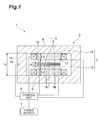
- the cyclotron 1 includes a yoke 2, a pole 3, a coil 4, a D electrode 5, a control unit (control means) 6, and a power source 7.
- the yoke 2 is a hollow member formed of iron or iron alloy (for example, cobalt iron alloy), a laminate of silicon copper plates, and the like.
- the yoke 2 is formed in a hollow disk shape by an upper yoke portion (first yoke portion) 8, a lower yoke portion (second yoke portion) 9, and a side yoke portion 10.
- the upper yoke portion 8 and the lower yoke portion 9 are approximately disk-shaped portions facing each other in the extending direction of the central axis C (vertical direction).
- the outer peripheral sides of the upper yoke portion 8 and the lower yoke portion 9 are connected to each other through the annular side yoke portion 10.
- Inner space closed by the upper yoke portion 8, the lower yoke portion 9, and the side yoke portion 10 is formed in the yoke 2, and the pole 3 and the coil 4 are disposed in this internal space.
- the upper yoke portion 8, the lower yoke portion 9, and the side yoke portion 10 do not need to be separate members, and may be formed integrally.
- the side yoke portion 10 does not need to be a single member, and may be formed of a plurality of members.
- the side yoke portion 10 may be divided vertically.
- the side yoke portion 10 means a portion located on the side of the internal space of the yoke 2. That is, the length Ly of the side yoke portion 10 in the vertical direction is equal to the length of the internal space in the vertical direction (distance between the upper yoke portion 8 and the lower yoke portion 9).
- the pole 3 is a magnetic pole for generating a magnetic field for controlling the ion beam, and is formed of iron or iron alloy (for example, cobalt iron alloy), a laminate of silicon copper plates, and the like, for example.
- the material of the pole 3 may be the same as the yoke 2, or may be different from the yoke 2.
- the pole 3 includes an upper pole (first pole) 12 fixed to the inner surface of the upper yoke portion 8 and a lower pole (second pole) 13 fixed to the inner surface of the lower yoke portion 9.
- a first coil 14 is disposed so as to surround the upper pole 12.
- a second coil 15 is disposed around the lower pole 13 so as to surround the lower pole 13.
- the upper pole 12 and the lower pole 13 are members having the same shape, and their lengths in the vertical direction (thicknesses) Lp are equal.
- a pole gap Lg is formed between the upper pole 12 and the lower pole 13.
- a pair of D electrodes 5 are provided in the pole gap Lg.
- the pole gap Lg is expressed as in the following Expression (1) using the length Ly of the side yoke portion 10 in the vertical direction and the length Lp of each of the upper pole 12 and the lower pole 13 in the vertical direction.
- one D electrode and one dummy D electrode may be provided.
- the pair of D electrodes 5 is a member for generating an electric field to accelerate the ion beam.
- the D electrode 5 is a fan-shaped member when viewed from the vertical direction, and has a cavity penetrated in the circumferential direction of the central axis C.
- a dummy D electrode 16 corresponding to the circumferential end portion is disposed in the D electrode 5.
- the D electrode 5 and the dummy D electrode 16 generate an electric field that changes in the circumferential direction by high-frequency AC current applied to the D electrode 5.
- the control unit 6 is an electronic control unit that controls the operation of the cyclotron 1.
- the control unit 6 includes a Central Processing Unit (CPU), a Read Only Memory (ROM), a Random Access Memory (RAM), and the like.
- the control unit 6 is connected to the coil 4, the D electrode 5, the power source 7, a pole temperature sensor (pole temperature detection means) 17, and a yoke temperature sensor (yoke temperature detection means) 18.
- the pole temperature sensor 17 is a sensor that detects the temperature of the upper pole 12.
- the pole temperature sensor 17 is disposed at the lower end of the right side end portion of the upper pole 12 in Fig. 1 .
- the yoke temperature sensor 18 is a sensor that detects the temperature of the side yoke portion 10.
- the yoke temperature sensor 18 is located at the approximate center of the side yoke portion 10 in the vertical direction (direction in which the upper pole 12 and the lower pole 13 face each other) at the left end of the side yoke portion 10 in Fig. 1 .
- the yoke temperature sensor 18 is disposed at a position that is equally distant from the upper pole 12 and the lower pole 13 and is far from the pole temperature sensor 17.
- the control unit 6 controls the supply of electric power from the power source 7 to the coil 4 and the D electrode 5.
- the control unit 6 controls the supply of electric power to the coil 4 and the D electrode 5 on the basis of the detection results of the pole temperature sensor 17 and the yoke temperature sensor 18.
- the heat input to the opposite surface of the upper pole 12 is transmitted to the upper yoke portion 8 through the upper pole 12, and a part of the heat is transmitted from the end of the upper yoke portion 8 to the side yoke portion 10.
- the heat input to the opposite surface of the lower pole 13 is transmitted to the lower yoke portion 9 through the lower pole 13, and a part of the heat is transmitted from the end of the lower yoke portion 9 to the side yoke portion 10.
- a variation ⁇ Lg of the pole gap Lg can be expressed as in the following Expression (2) using a variation ⁇ Ty from the reference temperature of the average temperature of the side yoke portion 10, a variation ⁇ Tp from the reference temperature of the average temperature of the upper pole 12 and the lower pole 13, and a linear expansion coefficient ⁇ of each of the upper pole 12, the lower pole 13, and the side yoke portion 10.
- the control unit 6 performs the supply of electric power to the coil 4 in consideration of the change in the pole gap Lg due to temperature on the basis of the detection results of the pole temperature sensor 17 and the yoke temperature sensor 18. Since the cyclotron 1 under operation has a heat distribution in which the side of the upper pole 12 to which heat is input is at a high temperature and the side of the yoke portion 10 is at a low temperature, the control unit 6 controls the supply of electric power in consideration of the distribution of heat from the upper pole 12 to the approximate center of the side yoke portion 10 on the basis of the detection results of the pole temperature sensor 17 and the yoke temperature sensor 18.
- a change ⁇ I in the amount of current with respect to the coil 4 can be expressed as in the following Expression (3) using the variation ⁇ Ty from the reference temperature (for example, room temperature) of the average temperature of the side yoke portion 10 and the variation ⁇ Tp from the reference temperature of the average temperature of the upper pole 12 and the lower pole 13.
- a and B are coefficients.
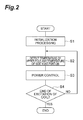
- predetermined initialization processing is performed when starting the excitation of the coil 4 (step S1). Then, the control unit 6 detects the temperature of the upper pole 12 using the pole temperature sensor 17 and detects the temperature of the side yoke portion 10 using the yoke temperature sensor 18 (step S2). The control unit 6 acquires the detection results of the pole temperature sensor 17 and the yoke temperature sensor 18.
- control unit 6 controls the supply of electric power to the coil 4 and the D electrode 5 on the basis of the detection results of the pole temperature sensor 17 and the yoke temperature sensor 18 (step S3).
- control unit 6 determines whether or not an instruction to end the excitation of the coil 4 has been input (step S4). When it is determined that no instruction to end the excitation of the coil 4 has been input, the control unit 6 returns to step S2 to repeat the process. When it is determined that an instruction to end the excitation of the coil 4 has been input, the control unit 6 ends the excitation of the coil 4. In addition, determination regarding the end of excitation of the coil 4 may be processed in another flow.
- the supply of electric power to the coil 4 is controlled on the basis of the temperature of the upper pole 12 and the temperature of the side yoke portion 10, a magnetic field can be accurately controlled reflecting the influence of the change in the pole gap Lg due to temperature even if the pole gap Lg is changed due to thermal expansion of the pole 3 and the yoke 2. As a result, it is possible to stabilize the control of the ion beam.
- the cyclotron 1 since the supply of electric power to the D electrode 5 is controlled on the basis of the temperature of the upper pole 12 and the temperature of the side yoke portion 10, an electric field can be accurately controlled reflecting the influence of the change in the pole gap Lg due to temperature. Therefore, according to the cyclotron 1, it is possible to further stabilize the control of the ion beam by a magnetic field and an electric field by improving the control accuracy of the magnetic field and the electric field.
- the yoke temperature sensor 18 is disposed at the approximate center of the side yoke portion 10 in the vertical direction, the temperature of the side yoke portion 10 can be detected at a position almost equally distant from the upper pole 12 and the lower pole 13 to which heat is applied. Therefore, compared with a case where the yoke temperature sensor 18 is disposed so as to be biased either above or below, the influence of the change in the pole gap Lg due to temperature can be accurately reflected in control by appropriately measuring the average temperature of the side yoke portion 10.
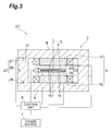
- a cyclotron 21 according to another embodiment is different from the cyclotron 1 according to the above-described embodiment only in that the number of temperature sensors has increased. Since components other than the temperature sensor are the same as in the above-described embodiment, the same reference numerals are given and explanation thereof will be omitted.
- a pole temperature sensor 22 of the cyclotron 21 includes a first pole temperature sensor 24 that detects the temperature of the upper pole 12 and a second pole temperature sensor 25 that detects the temperature of the lower pole 13.
- the first pole temperature sensor 24 is disposed at the same position as the pole temperature sensor 17 according to the above-described embodiment.
- the second pole temperature sensor 25 is disposed at the upper end of a right side end portion of the lower pole 13.
- a yoke temperature sensor 23 includes a first yoke temperature sensor 26 disposed at the approximate center of the side yoke portion 10 in the vertical direction, a second yoke temperature sensor 27 disposed on the boundary of the side yoke portion 10 and the upper yoke portion 8, and a third yoke temperature sensor 28 disposed on the boundary of the side yoke portion 10 and the lower yoke portion 9.
- the boundary of the side yoke portion 10 and the upper yoke portion 8 does not mean the boundary of members.
- the boundary of a portion located on the side of the internal space of the hollow yoke 2 and a portion located above from the internal space is equivalent to the boundary of the side yoke portion 10 and the upper yoke portion 8. The same is true for a case of the side yoke portion 10 and the lower yoke portion 9.
- the supply of electric power to the coil 4 and the D electrode 5 is controlled on the basis of the detection results of the first pole temperature sensor 24, the second pole temperature sensor 25, the first yoke temperature sensor 26, the second yoke temperature sensor 27, and the third yoke temperature sensor 28.
- the influence of a change in the pole gap can be accurately reflected in control by detecting the temperature of both the upper pole 12 and the lower pole 13. This is advantageous in stabilizing the control of the ion beam.
- the temperature sensors 2 7 and 28 can also be symmetrically disposed on the boundary of the upper pole 12 and the lower pole 13 of the side yoke portion 10, the average temperature of the side yoke portion 10 can be detected more accurately. Therefore, since the change in the pole gap Lg due to thermal expansion of the side yoke portion 10 can be more reliably reflected in control, it is possible to further stabilize the control of the ion beam.
- the present invention is not limited to the embodiments described above.
- the cyclotron according to the present invention is not limited to the horizontal type cyclotron in which a pair of poles face each other in the vertical direction, but may be a vertical type cyclotron in which a pair of poles face each other in the horizontal direction.
- a temperature sensor may be provided in the lower pole instead of the upper pole, and a temperature sensor may be provided in both the upper pole and the lower pole.
- the number of yoke temperature sensors may be 2 instead of 3.
Landscapes
- Physics & Mathematics (AREA)
- Engineering & Computer Science (AREA)
- Plasma & Fusion (AREA)
- Spectroscopy & Molecular Physics (AREA)
- Particle Accelerators (AREA)
- Plasma Technology (AREA)
Applications Claiming Priority (1)
| Application Number | Priority Date | Filing Date | Title |
|---|---|---|---|
| JP2012264564A JP6138466B2 (ja) | 2012-12-03 | 2012-12-03 | サイクロトロン |
Publications (1)
| Publication Number | Publication Date |
|---|---|
| EP2739124A1 true EP2739124A1 (en) | 2014-06-04 |
Family
ID=49679279
Family Applications (1)
| Application Number | Title | Priority Date | Filing Date |
|---|---|---|---|
| EP13020130.4A Withdrawn EP2739124A1 (en) | 2012-12-03 | 2013-11-27 | Cyclotron |
Country Status (4)
| Country | Link |
|---|---|
| US (1) | US9210794B2 (enExample) |
| EP (1) | EP2739124A1 (enExample) |
| JP (1) | JP6138466B2 (enExample) |
| CN (1) | CN103857168B (enExample) |
Families Citing this family (6)
| Publication number | Priority date | Publication date | Assignee | Title |
|---|---|---|---|---|
| JP5955709B2 (ja) * | 2012-09-04 | 2016-07-20 | 住友重機械工業株式会社 | サイクロトロン |
| JP6038694B2 (ja) * | 2013-03-12 | 2016-12-07 | 住友重機械工業株式会社 | サイクロトロン |
| JP6380939B2 (ja) * | 2016-05-09 | 2018-08-29 | 日本メジフィジックス株式会社 | サイクロトロン制御装置、サイクロトロン、サイクロトロン制御プログラムおよび放射性薬剤の製造方法 |
| CN106211540B (zh) * | 2016-07-29 | 2018-10-09 | 中国原子能科学研究院 | 230MeV超导回旋加速器防止引出区有害共振的机械结构 |
| CN106231778A (zh) * | 2016-08-31 | 2016-12-14 | 安徽思讯医疗科技有限公司 | 一种生产放射性同位素的超导回旋加速器 |
| BE1031179B1 (fr) * | 2022-12-23 | 2024-07-22 | Nanomarker Sprl | Cyclotron |
Citations (1)
| Publication number | Priority date | Publication date | Assignee | Title |
|---|---|---|---|---|
| JPH0677049A (ja) | 1992-08-24 | 1994-03-18 | Hitachi Ltd | 荷電粒子加速器用の電磁石装置および荷電粒子加速器システム |
Family Cites Families (15)
| Publication number | Priority date | Publication date | Assignee | Title |
|---|---|---|---|---|
| US3363138A (en) * | 1964-11-04 | 1968-01-09 | Sperry Rand Corp | Electron beam-plasma device operating at multiple harmonics of beam cyclotron frequency |
| JPS5123675B2 (enExample) * | 1973-11-02 | 1976-07-19 | ||
| JP3325982B2 (ja) * | 1993-12-27 | 2002-09-17 | 株式会社東芝 | 磁界界浸型電子銃 |
| JP3705861B2 (ja) * | 1996-03-21 | 2005-10-12 | 株式会社日立メディコ | 超電導磁石装置及びその着磁調整方法 |
| JP3137233B2 (ja) * | 1996-12-18 | 2001-02-19 | 川崎重工業株式会社 | 超電導ウィグラ励磁方法および超電導ウィグラ |
| SE513192C2 (sv) * | 1998-09-29 | 2000-07-24 | Gems Pet Systems Ab | Förfarande och system för HF-styrning |
| JP2000150199A (ja) * | 1998-11-04 | 2000-05-30 | Sumitomo Heavy Ind Ltd | 電磁石の磁場安定化装置 |
| EP1069809A1 (en) * | 1999-07-13 | 2001-01-17 | Ion Beam Applications S.A. | Isochronous cyclotron and method of extraction of charged particles from such cyclotron |
| JP3987686B2 (ja) * | 2001-02-02 | 2007-10-10 | ジーイー・メディカル・システムズ・グローバル・テクノロジー・カンパニー・エルエルシー | 静磁界補正方法およびmri装置 |
| JP4251648B2 (ja) * | 2004-01-23 | 2009-04-08 | 日立金属株式会社 | 挿入光源 |
| JP4541092B2 (ja) * | 2004-10-04 | 2010-09-08 | 株式会社日立製作所 | 磁気共鳴イメージング装置の超伝導磁石装置 |
| ES2587982T3 (es) * | 2005-11-18 | 2016-10-28 | Mevion Medical Systems, Inc | Radioterapia con partículas cargadas |
| US7656258B1 (en) * | 2006-01-19 | 2010-02-02 | Massachusetts Institute Of Technology | Magnet structure for particle acceleration |
| CN102148083B (zh) * | 2010-02-09 | 2013-04-03 | 通用电气公司 | 超导磁体 |
| JP6091999B2 (ja) * | 2012-06-01 | 2017-03-08 | 住友重機械工業株式会社 | サイクロトロン |
-
2012
- 2012-12-03 JP JP2012264564A patent/JP6138466B2/ja active Active
-
2013
- 2013-11-04 CN CN201310538024.8A patent/CN103857168B/zh active Active
- 2013-11-27 EP EP13020130.4A patent/EP2739124A1/en not_active Withdrawn
- 2013-12-02 US US14/093,855 patent/US9210794B2/en not_active Expired - Fee Related
Patent Citations (1)
| Publication number | Priority date | Publication date | Assignee | Title |
|---|---|---|---|---|
| JPH0677049A (ja) | 1992-08-24 | 1994-03-18 | Hitachi Ltd | 荷電粒子加速器用の電磁石装置および荷電粒子加速器システム |
Non-Patent Citations (3)
| Title |
|---|
| ARAKAWA K. ET AL: "Construction and first year's operation of the JAERI AVF cyclotron", PROCEEDINGS OF CYCLOTRONS AND THEIR APPLICATIONS 1992; 13TH INTERNATIONAL CONFERENCE, 1992, pages 119 - 122, XP002720426 * |
| NINOMIYA S. ET AL: "RCNP Techniques for Producing Ultra-precise Beams", CYCLOTRONS AND THEIR APPLICATIONS 2001, 16TH INTERNATIONAL CONFERENCE, 2001, pages 94 - 98, XP002720424, ISSN: 0094-243X * |
| OKUMURA S. ET AL: "Magnetic field stabilisation by temperature control of an azimuthally varying field cyclotron magnet", REVIEW OF SCIENTIFIC INSTRUMENTS, vol. 76, no. 033301, 2005, pages 033301-1 - 033301-6, XP002720425 * |
Also Published As
| Publication number | Publication date |
|---|---|
| US9210794B2 (en) | 2015-12-08 |
| JP2014110180A (ja) | 2014-06-12 |
| US20140152198A1 (en) | 2014-06-05 |
| CN103857168B (zh) | 2016-05-11 |
| CN103857168A (zh) | 2014-06-11 |
| JP6138466B2 (ja) | 2017-05-31 |
Similar Documents
| Publication | Publication Date | Title |
|---|---|---|
| EP2739124A1 (en) | Cyclotron | |
| Klaiber et al. | Under-the-barrier dynamics in laser-induced relativistic tunneling | |
| JP7097879B2 (ja) | 磁気粒子イメージング | |
| US8710473B2 (en) | Droplet generation and detection device, and droplet control device | |
| CN109005635B (zh) | 回旋加速器及其控制方法 | |
| SE513190C2 (sv) | Metod och system för minimerande av magnetstorlek i en cyclotron | |
| Cai et al. | Design of undercuts and dipole stabilizer rods for the CPHS RFQ accelerator | |
| KR101380996B1 (ko) | 자기장 센서를 이용한 마이크로 로봇 제어장치 | |
| CN103370991B (zh) | 切割电磁铁及粒子射线治疗装置 | |
| Tosin et al. | Super hybrid quadrupoles | |
| Grigoryev et al. | Machine studies for the development of storage cells at the ANKE facility of COSY | |
| Yu-Fang et al. | Design and simulation of a wire scanner for the CSNS linac | |
| US20220181042A1 (en) | Scanning magnet and particle therapy system | |
| CN102832533B (zh) | 一种提高塞曼双频激光器频差的装置 | |
| EP2560782A1 (en) | Apparatus and methods for reducing the ambient magnetic field strength to facilitate arc welding | |
| JP6031505B2 (ja) | 電磁力平衡式計量装置 | |
| JP7055001B2 (ja) | モータの制御方法、及び、モータの制御装置 | |
| Powell et al. | Arc dynamics in the rail gun | |
| Jung et al. | Central region of SKKUCY-9 compact cyclotron | |
| JP4399604B2 (ja) | 荷電粒子ビームの軌道制御装置及びその制御方法 | |
| JP2022158334A (ja) | 電磁石装置、電磁石装置の制御方法、および、粒子線治療装置 | |
| JP2013165055A (ja) | セプタム電磁石の制御方法 | |
| JP6832711B2 (ja) | 超伝導電磁石装置及び超伝導電磁石装置における磁場補正方法 | |
| Press et al. | Experimental verification of DARHT Axis 1 injector PIC simulations | |
| Mordvintsev et al. | Accounting for the Edge Effects of Electric and Magnetic Fields in the Spectroscopy of Ion Flows from Relativistic Laser Plasma |
Legal Events
| Date | Code | Title | Description |
|---|---|---|---|
| PUAI | Public reference made under article 153(3) epc to a published international application that has entered the european phase |
Free format text: ORIGINAL CODE: 0009012 |
|
| 17P | Request for examination filed |
Effective date: 20131127 |
|
| AK | Designated contracting states |
Kind code of ref document: A1 Designated state(s): AL AT BE BG CH CY CZ DE DK EE ES FI FR GB GR HR HU IE IS IT LI LT LU LV MC MK MT NL NO PL PT RO RS SE SI SK SM TR |
|
| AX | Request for extension of the european patent |
Extension state: BA ME |
|
| GRAP | Despatch of communication of intention to grant a patent |
Free format text: ORIGINAL CODE: EPIDOSNIGR1 |
|
| RIC1 | Information provided on ipc code assigned before grant |
Ipc: H05H 7/02 20060101AFI20181005BHEP |
|
| INTG | Intention to grant announced |
Effective date: 20181025 |
|
| STAA | Information on the status of an ep patent application or granted ep patent |
Free format text: STATUS: THE APPLICATION IS DEEMED TO BE WITHDRAWN |
|
| 18D | Application deemed to be withdrawn |
Effective date: 20190305 |