EP2738334A2 - Türbetätiger - Google Patents
Türbetätiger Download PDFInfo
- Publication number
- EP2738334A2 EP2738334A2 EP13005407.5A EP13005407A EP2738334A2 EP 2738334 A2 EP2738334 A2 EP 2738334A2 EP 13005407 A EP13005407 A EP 13005407A EP 2738334 A2 EP2738334 A2 EP 2738334A2
- Authority
- EP
- European Patent Office
- Prior art keywords
- door operator
- piston
- operator according
- disc
- housing
- Prior art date
- Legal status (The legal status is an assumption and is not a legal conclusion. Google has not performed a legal analysis and makes no representation as to the accuracy of the status listed.)
- Withdrawn
Links
- 238000005253 cladding Methods 0.000 abstract description 3
- 210000002414 leg Anatomy 0.000 description 10
- 238000013016 damping Methods 0.000 description 6
- 239000010720 hydraulic oil Substances 0.000 description 3
- 238000004519 manufacturing process Methods 0.000 description 2
- 239000003921 oil Substances 0.000 description 2
- 238000003825 pressing Methods 0.000 description 2
- 239000007787 solid Substances 0.000 description 2
- 238000003856 thermoforming Methods 0.000 description 2
- 230000004308 accommodation Effects 0.000 description 1
- 238000004026 adhesive bonding Methods 0.000 description 1
- 230000005540 biological transmission Effects 0.000 description 1
- 230000000295 complement effect Effects 0.000 description 1
- 238000010276 construction Methods 0.000 description 1
- 230000001419 dependent effect Effects 0.000 description 1
- 238000013461 design Methods 0.000 description 1
- 238000011161 development Methods 0.000 description 1
- 230000018109 developmental process Effects 0.000 description 1
- 238000007765 extrusion coating Methods 0.000 description 1
- 238000003780 insertion Methods 0.000 description 1
- 230000037431 insertion Effects 0.000 description 1
- 238000012423 maintenance Methods 0.000 description 1
- 239000002184 metal Substances 0.000 description 1
- 238000000034 method Methods 0.000 description 1
- 238000005096 rolling process Methods 0.000 description 1
- 230000006641 stabilisation Effects 0.000 description 1
- 238000011105 stabilization Methods 0.000 description 1
- 210000000689 upper leg Anatomy 0.000 description 1
- 238000003466 welding Methods 0.000 description 1
Images


Classifications
-
- E—FIXED CONSTRUCTIONS
- E05—LOCKS; KEYS; WINDOW OR DOOR FITTINGS; SAFES
- E05F—DEVICES FOR MOVING WINGS INTO OPEN OR CLOSED POSITION; CHECKS FOR WINGS; WING FITTINGS NOT OTHERWISE PROVIDED FOR, CONCERNED WITH THE FUNCTIONING OF THE WING
- E05F3/00—Closers or openers with braking devices, e.g. checks; Construction of pneumatic or liquid braking devices
- E05F3/04—Closers or openers with braking devices, e.g. checks; Construction of pneumatic or liquid braking devices with liquid piston brakes
- E05F3/10—Closers or openers with braking devices, e.g. checks; Construction of pneumatic or liquid braking devices with liquid piston brakes with a spring, other than a torsion spring, and a piston, the axes of which are the same or lie in the same direction
- E05F3/104—Closers or openers with braking devices, e.g. checks; Construction of pneumatic or liquid braking devices with liquid piston brakes with a spring, other than a torsion spring, and a piston, the axes of which are the same or lie in the same direction with cam-and-slide transmission between driving shaft and piston within the closer housing
-
- E—FIXED CONSTRUCTIONS
- E05—LOCKS; KEYS; WINDOW OR DOOR FITTINGS; SAFES
- E05F—DEVICES FOR MOVING WINGS INTO OPEN OR CLOSED POSITION; CHECKS FOR WINGS; WING FITTINGS NOT OTHERWISE PROVIDED FOR, CONCERNED WITH THE FUNCTIONING OF THE WING
- E05F3/00—Closers or openers with braking devices, e.g. checks; Construction of pneumatic or liquid braking devices
- E05F3/04—Closers or openers with braking devices, e.g. checks; Construction of pneumatic or liquid braking devices with liquid piston brakes
- E05F3/10—Closers or openers with braking devices, e.g. checks; Construction of pneumatic or liquid braking devices with liquid piston brakes with a spring, other than a torsion spring, and a piston, the axes of which are the same or lie in the same direction
- E05F3/102—Closers or openers with braking devices, e.g. checks; Construction of pneumatic or liquid braking devices with liquid piston brakes with a spring, other than a torsion spring, and a piston, the axes of which are the same or lie in the same direction with rack-and-pinion transmission between driving shaft and piston within the closer housing
-
- E—FIXED CONSTRUCTIONS
- E05—LOCKS; KEYS; WINDOW OR DOOR FITTINGS; SAFES
- E05Y—INDEXING SCHEME ASSOCIATED WITH SUBCLASSES E05D AND E05F, RELATING TO CONSTRUCTION ELEMENTS, ELECTRIC CONTROL, POWER SUPPLY, POWER SIGNAL OR TRANSMISSION, USER INTERFACES, MOUNTING OR COUPLING, DETAILS, ACCESSORIES, AUXILIARY OPERATIONS NOT OTHERWISE PROVIDED FOR, APPLICATION THEREOF
- E05Y2900/00—Application of doors, windows, wings or fittings thereof
- E05Y2900/10—Application of doors, windows, wings or fittings thereof for buildings or parts thereof
- E05Y2900/13—Type of wing
- E05Y2900/132—Doors
Definitions
- the present invention relates to a door operator for opening and / or closing a door leaf.
- the prior art knows various types of door operators, in particular door closers, power door closers or door drives.
- the door operator is attached either directly to the door leaf or to the wall or frame. If the door operator is on the wall or frame, an output shaft of the door operator is connected to the door leaf via a linkage. If the door operator is located directly on the door leaf, the linkage connects the output shaft with a slide rail on the wall or frame.
- the rotational movement of the output shaft is converted by means of pistons into a linear movement for tensioning a closing spring.
- the linearly guided pistons are integral rotary milled parts.
- a door operator comprising a housing and a rotatably mounted in the housing output shaft.
- the door leaf is actuated via the output shaft.
- the door operator For example, on the door leaf, the force is transmitted to the frame or a wall via the output shaft and a linkage. If the door operator is on the wall or the frame, the force is transmitted to the door leaf via the output shaft and a corresponding linkage.
- the output shaft can be arranged coaxially to the axis of rotation of the door. It requires no linkage for power transmission.
- the door operator according to the invention further comprises at least one piston guided linearly in the housing.
- the piston cooperates with the output shaft, so that a rotational movement of the output shaft can be converted into a linear movement of the piston, and vice versa.
- the piston is constructed in several parts and thus comprises a supporting framework and at least one tubular, the framework enveloping shell component.
- the multi-part construction of the piston allows a very simple and lightweight piston design.
- the jacket component is preferably fastened to the framework by form-fitting insertion and / or pressing and / or shrinking. Furthermore, it is preferably provided to loosely assemble the individual components of the piston and to achieve a firm cohesion by pressing the piston into the housing.
- the individual components, in particular the supporting framework and the enveloping jacket component can be connected to one another by welding and / or gluing and / or extrusion coating.
- an outer surface of the shell component is designed for guidance on an inner surface of the housing.
- the outer surface of the jacket component is in particular cylindrical.
- a pressure roller is preferably rotatably mounted.
- the supporting framework preferably has a U-shaped roller carrier.
- This roller carrier comprises two opposite legs. On the legs of the pressure roller is mounted.
- a bolt is preferably provided. The two ends of the bolt are stuck in the legs of the U-shaped roller carrier.
- the pressure roller for example, with needle-shaped rolling elements, rotatably mounted.
- the U-shaped roller carrier is in particular formed in one piece, for example as a bent sheet metal part.
- a cam disc On the output shaft of the door operator, a cam disc is preferably arranged.
- the pressure roller arranged in the piston rolls on the cam disk. Due to the contour of the cam disk, the piston is moved linearly during a rotation of the output shaft.
- the framework preferably comprises a cross-shaped support beam.
- the support beam is preferably composed of two mutually perpendicular support plates.
- the two carrier plates are preferably inserted into one another in a form-fitting manner.
- the cross-shaped support bracket supports the shell component inside the piston.
- the jacket member can be relatively easily formed and serves primarily only as a guide surface of the piston in the housing.
- the framework preferably comprises a first disc. This first disc forms a first end face of the piston.
- the jacket component is preferably located on a cylindrical outer surface of the first disc.
- the framework preferably comprises a second disc.
- This second disc is opposite the first disc and thus forms the second end face of the piston.
- the first and / or the second disc are preferably on the support bracket.
- the first disc and / or the second disc are connected to the support carrier.
- the first and / or the second disc have the cylindrical outer surface on which the jacket component rests or is attached. It is preferably provided that pins are formed on the cylindrical outer surface. To the pins complementary grooves are formed in the shell component. The pins stuck in the grooves, so that the jacket member is connected against rotation with the first and / or the second disc.
- the shell component is a simple tube.
- the thermoforming component has a bottom. This bottom forms, instead of the second disc, the second end face of the piston.
- the floor does not have to extend over the complete second end face, but may have a central recess.
- the decisive factor is that the floor represents a bearing surface for the framework.
- the jacket component comprises two individual, tubular parts.
- the two individual, tubular parts are spaced from each other mounted on the frame, so that an annular groove is formed between the two parts.
- the tubular shell component is designed in particular thin-walled.
- the wall thickness of the jacket component is preferably between 1 mm and 10 mm, more preferably between 2 mm and 8 mm.
- the jacket component and the framework have an internal cavity.
- a volume body is preferably inserted into the cavity.
- the solid is in particular cylindrical.
- the cavity is preferably used as a hydraulic tank and / or hydraulic compensation chamber.
- This use of the cavity is independent of the volume used, since despite the volume body a corresponding cavity can remain.
- at least one hydraulic line leads into the cavity.
- the door operator has two pistons guided linearly in the housing.
- the one piston is used as a "damping piston” and displaces an oil volume to dampen the movement of the door leaf.
- the second piston is used as a "closing piston” and cooperates with an energy store, in particular a spring.
- Both pistons have a pressure roller that rolls on the cam.
- the cam disk is located between the two pistons and thus between the two pressure rollers.
- the two pistons are connected to each other via at least one connecting element.
- This connecting element is preferably designed as one or more rods.
- the rods extend beside or below or above the cam disc between the two pistons.
- the at least one connecting element is preferably formed integrally with the U-shaped roller carrier of one of the two pistons. In particular, it is provided that the at least one connecting element is formed as an integral extension of a leg of the roller carrier.
- Fig. 1 shows the structure of a door operator 1 for all embodiments.
- the door operator 1 has a housing 2.
- an output shaft 3 is rotatably mounted in the housing 2.
- the output shaft 3 is connected, for example via a linkage, with the door leaf.
- a cam disk 4th On the output shaft 3 is a cam disk 4th
- a first piston 5 On one side of the cam disk 4, a first piston 5 is arranged, on the other side of the cam disk 4, a second piston 6 is arranged.
- the two pistons 5, 6 are guided in the housing 2 linearly movable.
- each piston 5, 6 each have a pressure roller 7 is arranged.
- the pressure rollers 7 are rotatably mounted on bolts 13.
- the bolts 13 are rotatably received in the piston 5, 6.
- damping chamber 8 Between a front side of the housing 2 and the first piston 5 is a damping chamber 8.
- This damping chamber 8 is filled with hydraulic oil. During a movement of the first piston 5, the hydraulic oil is displaced in the damping chamber 8, so that a damping of the movement of the door leaf is achieved.
- the second piston 6 is operatively connected via a freewheel assembly 9 with a closing spring 10.
- the closing spring 10 could also rest directly on the second piston 6.
- Present door operator 1 is designed as a door closer.
- the output shaft 3 and thus the cam plate 4 is set in rotation.
- the two pressure rollers 7 rest on the cam disk 4, so that the two pistons 5, 6 are moved by a rotation of the cam disk 4.
- the two pistons 5, 6 are moved to the right, so that the closing spring 10 is tensioned.
- the closing spring 10 relaxes and moves the pistons 5, 6 to the left. This leads to an opposite rotation of the cam disc 4 and output shaft 3 and consequently to a closing movement of the door leaf.
- the second piston 6 can be constructed analogously to the first piston 5.
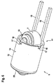
- FIG. 2 shows the piston 5 according to the first embodiment.
- the piston 5 is composed of a supporting frame 11 and a shell member 11 placed on the frame 11.
- the pressure roller 7 is rotatably mounted on the bolt 13.
- two connecting elements 15 are formed. By means of these connecting elements 15, the first piston 5 can be connected to the second piston 6.
- FIG. 3 the jacket component 12 is hidden.
- FIG. 4 Furthermore, the pressure roller 7 and the bolt 13 are hidden.
- FIG. 5 shows only a cross-shaped support beam 21 of the frame 11 in an exploded view.
- the jacket component 12 has a cylindrical outer surface 14. With this outer surface 14 of the piston 5 is guided in the housing 2 linearly movable. On the frame 11 a plurality of pins 17 are formed. In the jacket component 12 grooves 16 are provided. The pins 17 stuck in the grooves 16, so that a rotationally fixed connection between the jacket member 12 and the frame 11 is formed.
- FIGS. 3 to 5 show the structure of the frame 11 in detail.
- the frame 11 is composed of a U-shaped roller carrier 18.
- the U-shaped roller carrier 18 has two opposite legs 19.
- the two legs 19 are connected by a rear wall 20 with each other.
- Integral part of a leg 19 are the two connecting elements 15.
- the U-shaped roller carrier 18 with the two legs 19, the rear wall 20 and the connecting elements 15 is integrally, for example, as a stamped and bent part manufactured.
- each leg 19 each have a bolt receptacle 24, designed as a through hole, provide.
- the bolt 13 is inserted in these two bolt receptacles 24.
- the rear wall 20 has retaining grooves 25. With these retaining grooves 25, the U-shaped roller carrier 18 is inserted in the cross-shaped support beam 21st
- the frame 11 comprises two opposite discs 22, 23.
- the two discs 22, 23 form the two end faces of the piston 5.
- On each of the discs 22, 23 a cylindrical receiving surface 30 is formed.
- the pins 17 are arranged on this receiving surface 30.
- the first disc 22 has a recess in which the two legs 19 and the pressure roller 7 stuck.
- the pressure roller 7 thus protrudes through the first disc 22, so that one half of the pressure roller 7 is arranged in the interior of the first piston 5.
- the other half of the pressure roller 7 protrudes from the first piston 5, and thus can roll on the cam plate 4.
- the two discs 22, 23 abut the cross-shaped support beam 21, and are in particular firmly connected to the cross-shaped support beam 21.
- FIG. 5 shows in an exploded view, a first support plate 26 and a second support plate 27. These two support plates 26, 27 together form the cross-shaped support bracket 21. In the support plates 26, 27 FormQuerynuten 28 are formed. These two form-fitting grooves 28 are inserted into one another, so that the two support plates 26, 27 are fixed at an angle of 90 ° to each other. Furthermore, the second carrier plate 27 has a roller carrier recess 29. In this roller carrier recess 29 of the roller carrier 18 sits.
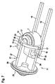
- FIGS. 6 and 7 show the first piston 5 according to the second embodiment. In FIG. 7 the jacket component 12 is hidden.
- the second disc 23 is formed as a rotating part.
- the second disk 23 here likewise has a cylindrical receiving surface 30 for the jacket component 12. However, there are no pins 17 on this cylindrical receiving surface 30.
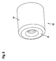
- FIGS. 8 and 9 show the piston 5 according to a third embodiment.
- the jacket component 12 is a deep-drawn component.
- This thermoforming component has a bottom 31 and is thus cup-shaped.
- the second disc 23 is omitted and by replaced the floor 31.
- the pins 17 on the receiving surface 30 of the first disc 22 omitted.
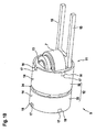
- FIG. 10 and 11 show the piston 5 according to a fourth embodiment. In FIG. 11 the jacket component 12 is hidden.
- the jacket member 12 is formed in two parts and thus comprises two tubular parts 32, 33.
- the two tubular parts 32, 33 are spaced apart from each other onto the frame 11, so that between the two parts 32, 33, an annular groove 34 is formed.
- the annular groove 34 is provided for the meaningful accommodation of piston seals or piston lip rings and / or guide bands and / or piston rings.
- FIG. 11 shows, in the fourth embodiment, a volume body 35 is inserted between the shell member 12 and the frame 11.
- the volume body 35 is cylindrical and serves for further stabilization.
- the volume body 35 is used in particular for the realization of the annular groove 34, but can also be used in the other embodiments.
- volume body 35 is formed in the interior of the frame 11, a cavity which can be used for example as a hydraulic tank or hydraulic compensation room.
Landscapes
- Closing And Opening Devices For Wings, And Checks For Wings (AREA)
- Casings For Electric Apparatus (AREA)
Abstract
Description
- Vorliegende Erfindung betrifft einen Türbetätiger zum Öffnen und/oder Schließen eines Türblattes.
- Der Stand der Technik kennt verschiedene Bauarten von Türbetätigern, insbesondere Türschließer, Servotürschließer oder Türantriebe. Der Türbetätiger wird entweder direkt am Türblatt oder an der Wand bzw. Zarge befestigt. Befindet sich der Türbetätiger an Wand oder Zarge, so wird eine Abtriebswelle des Türbetätigers über ein Gestänge mit dem Türblatt verbunden. Befindet sich der Türbetätiger direkt am Türblatt, so verbindet das Gestänge die Abtriebswelle mit einer Gleitschiene an der Wand oder Zarge. Innerhalb der Türbetätiger wird die Drehbewegung der Abtriebswelle mittels Kolben in eine lineare Bewegung zum Spannen einer Schließerfeder umgewandelt. In herkömmlichen Anordnungen sind die linear geführten Kolben einstückige Dreh-Frästeile.
- Es ist Aufgabe vorliegender Erfindung, einen Türbetätiger anzugeben, der bei kostengünstiger Herstellung und Montage betriebssicher und wartungsarm funktioniert.
- Die Lösung der Aufgabe erfolgt durch die Merkmale des Anspruchs 1. Die Unteransprüche haben bevorzugte Weiterbildungen der Erfindung zum Gegenstand.
- Somit wird die Aufgabe gelöst durch einen Türbetätiger umfassend ein Gehäuse und eine im Gehäuse drehbeweglich gelagerte Abtriebswelle. Über die Abtriebswelle wird das Türblatt betätigt. Befindet sich der Türbetätiger beispielsweise auf dem Türblatt, so wird über die Abtriebswelle und ein Gestänge die Kraft auf die Zarge oder eine Wand übertragen. Befindet sich der Türbetätiger an der Wand oder der Zarge, so wird über die Abtriebswelle und ein entsprechendes Gestänge die Kraft auf das Türblatt übertragen. In einer dritten Alternative kann die Abtriebswelle koaxial zur Drehachse der Türe angeordnet werden. Dabei bedarf es keines Gestänges zur Kraftübertragung. Der erfindungsgemäße Türbetätiger umfasst des Weiteren zumindest einen im Gehäuse linear geführten Kolben. Dieser Kolben wirkt mit der Abtriebswelle zusammen, so dass eine rotatorische Bewegung der Abtriebswelle in eine lineare Bewegung des Kolbens überführbar ist, und umgekehrt. Der Kolben ist mehrteilig aufgebaut und umfasst somit ein tragendes Gerüst und zumindest ein rohrförmiges, das Gerüst umhüllendes Mantelbauteil. Der mehrteilige Aufbau des Kolbens ermöglicht eine sehr einfache und leichte Kolbenbauweise. Das Mantelbauteil wird vorzugsweise durch form-schlüssiges Stecken und/oder Pressen und/oder Schrumpfen auf dem Gerüst befestigt. Des Weiteren ist bevorzugt vorgesehen, die einzelnen Bauteile des Kolbens locker zusammenzufügen und durch Eindrücken des Kolbens in das Gehäuse einen festen Zusammenhalt zu erreichen. Des Weiteren können die einzelnen Bauteile, insbesondere das tragende Gerüst und das umhüllende Mantelbauteil, durch Schweißen und/oder Kleben und/oder Umspritzen miteinander verbunden werden.
- Bevorzugt ist eine Außenfläche des Mantelbauteils zur Führung an einer Innenfläche des Gehäuses ausgebildet. Hierzu ist die Außenfläche des Mantelbauteils insbesondere zylindrisch.
- Im Gerüst des Kolbens ist bevorzugt eine Druckrolle drehbeweglich gelagert. Das tragende Gerüst weist vorzugsweise einen U-förmigen Rollenträger auf. Dieser Rollenträger umfasst zwei gegenüberliegende Schenkel. An den Schenkeln ist die Druckrolle gelagert. Hierzu ist bevorzugt ein Bolzen vorgesehen. Die beiden Enden des Bolzens stecken in den Schenkeln des U-förmigen Rollenträgers. Auf dem Bolzen ist die Druckrolle, beispielsweise mit nadelförmigen Wälzkörpern, drehbeweglich gelagert. Der U-förmige Rollenträger ist insbesondere einstückig ausgebildet, beispielsweise als ein gebogenes Blechteil.
- Auf der Abtriebswelle des Türbetätigers wird bevorzugt eine Nockenscheibe angeordnet. Die in dem Kolben angeordnete Druckrolle rollt auf der Nockenscheibe ab. Aufgrund der Kontur der Nockenscheibe wird bei einer Rotation der Abtriebswelle der Kolben linear bewegt.
- Des Weiteren umfasst das Gerüst bevorzugt einen kreuzförmigen Stützträger. Der Stützträger ist vorzugsweise aus zwei zueinander rechtwinkligen Trägerplatten zusammengesetzt. Die beiden Trägerplatten werden vorzugsweise formschlüssig ineinandergesteckt. Der kreuzförmige Stützträger stützt im Inneren des Kolbens das Mantelbauteil. Dadurch kann das Mantelbauteil relativ leicht ausgebildet werden und dient in erster Linie nur als Führungsfläche des Kolbens im Gehäuse.
- Das Gerüst umfasst bevorzugt eine erste Scheibe. Diese erste Scheibe bildet eine erste Stirnseite des Kolbens. Das Mantelbauteil liegt vorzugsweise auf einer zylindrischen Außenfläche der ersten Scheibe auf.
- Des Weiteren umfasst das Gerüst bevorzugt eine zweite Scheibe. Diese zweite Scheibe liegt der ersten Scheibe gegenüber und bildet somit die zweite Stirnseite des Kolbens. Die erste und/oder die zweite Scheibe liegen bevorzugt am Stützträger an. Insbesondere ist vorgesehen, dass die erste Scheibe und/oder die zweite Scheibe mit dem Stützträger verbunden sind.
- Die erste und/oder die zweite Scheibe weisen die zylindrische Außenfläche auf, auf der das Mantelbauteil aufliegt bzw. aufgesteckt ist. Bevorzugt ist vorgesehen, dass auf der zylindrischen Außenfläche Zapfen ausgebildet sind. Zu den Zapfen sind im Mantelbauteil komplementäre Nuten ausgebildet. Die Zapfen stecken in den Nuten, so dass das Mantelbauteil verdrehsicher mit der ersten und/oder der zweiten Scheibe verbunden ist.
- In einer einfachen Ausbildung ist das Mantelbauteil ein einfaches Rohr. Alternativ dazu ist es möglich, das Mantelbauteil durch einen Tiefziehprozess zu fertigen. Das Tiefziehbauteil weist einen Boden auf. Dieser Boden bildet, anstatt der zweiten Scheibe, die zweite Stirnseite des Kolbens. Der Boden muss sich nicht über die vollständige zweite Stirnseite erstrecken, sondern kann eine mittige Aussparung aufweisen. Ausschlaggebend ist, dass der Boden eine Auflagefläche für das Gerüst darstellt.
- Des Weiteren ist bevorzugt vorgesehen, dass das Mantelbauteil zwei einzelne, rohrförmige Teile umfasst. Die beiden einzelnen, rohrförmigen Teile sind beabstandet voneinander auf das Gerüst aufgesteckt, so dass zwischen den beiden Teilen eine Ringnut entsteht.
- Das rohrförmige Mantelbauteil ist insbesondere dünnwandig ausgeführt. Die Wandstärke des Mantelbauteils liegt bevorzugt zwischen 1 mm und 10mm, besonders bevorzugt zwischen 2mm und 8mm.
- Das Mantelbauteil und das Gerüst weisen einen innenliegenden Hohlraum auf. Zur Verbesserung der Stabilität des Kolbens ist in den Hohlraum bevorzugt ein Volumenkörper eingesetzt. Der Volumenkörper ist insbesondere zylindrisch.
- Des Weiteren wird der Hohlraum bevorzugt als Hydrauliktank und/oder Hydraulikausgleichsraum genutzt. Diese Nutzung des Hohlraums ist unabhängig vom eingesetzten Volumenkörper, da trotz des Volumenkörpers ein entsprechender Hohlraum verbleiben kann. Insbesondere für kleine Türbetätiger bietet es sich an, den Hohlraum als Tank- oder Ausgleichsraum für Hydrauliköl zu nutzen. Dies erhöht die Systemsicherheit, da aufgrund von ausreichendem Tank- oder Ausgleichsvolumen, beispielsweise bei unterschiedlichen Ölfüllungen und Temperaturunterschieden, ein Platzen im Türbetätiger vermieden wird. Insbesondere ist vorgesehen, dass zumindest eine Hydraulikleitung in den Hohlraum führt.
- Der Türbetätiger weist insbesondere zwei im Gehäuse linear geführte Kolben auf. Dabei kann nur einer der beiden Kolben oder es können beide Kolben gemäß vorliegender Erfindung ausgestaltet sein. Der eine Kolben wird als "Dämpfungskolben" benutzt und verdrängt ein Ölvolumen zum Dämpfen der Bewegung des Türblattes. Der zweite Kolben wird als "Schließkolben" genutzt und wirkt mit einem Energiespeicher, insbesondere einer Feder, zusammen. Beide Kolben weisen eine Druckrolle auf, die auf der Nockenscheibe abrollt. Die Nockenscheibe befindet sich zwischen den beiden Kolben und somit zwischen den beiden Druckrollen. Die beiden Kolben sind über zumindest ein Verbindungselement miteinander verbunden. Dieses Verbindungselement ist bevorzugt ausgebildet als eine oder mehrere Stangen. Die Stangen erstrecken sich neben bzw. unter oder über der Nockenscheibe zwischen den beiden Kolben. Das zumindest eine Verbindungselement wird bevorzugt einstückig mit dem U-förmigen Rollenträger eines der beiden Kolben ausgebildet. Insbesondere ist vorgesehen, dass das zumindest eine Verbindungselement als ein integraler Fortsatz eines Schenkels des Rollenträgers ausgebildet ist.
- Die Erfindung wird nun anhand von Ausführungsbeispielen näher beschrieben. Dabei zeigen:
- Figur 1
- einen erfindungsgemäßen Türbetätiger gemäß allen Ausführungsbeispielen,
- Figur 2
- einen Kolben des erfindungsgemäßen Türbetätigers gemäß einem ersten Ausführungsbeispiel,
- Figur 3
- ein erstes Detail zu
Figur 2 , - Figur 4
- ein zweites Detail zu
Figur 2 , - Figur 5
- ein drittes Detail zu
Figur 2 , - Figur 6
- einen Kolben des erfindungsgemäßen Türbetätigers gemäß einem zweiten Ausführungsbeispiel,
- Figur 7
- ein Detail zu
Figur 6 , - Figur 8
- einen Kolben des erfindungsgemäßen Türbetätigers gemäß einem dritten Ausführungsbeispiel,
- Figur 9
- ein Detail zu
Figur 8 , - Figur 10
- einen Kolben des erfindungsgemäßen Türbetätigers gemäß einem vierten Ausführungsbeispiel, und
- Figur 11
- ein Detail zu
Figur 10 . -
Fig. 1 zeigt den Aufbau eines Türbetätigers 1 für alle Ausführungsbeispiele. - Gemäß
Fig. 1 weist der Türbetätiger 1 ein Gehäuse 2 auf. In dem Gehäuse 2 ist eine Abtriebswelle 3 drehbeweglich gelagert. Die Abtriebswelle 3 wird, beispielsweise über ein Gestänge, mit dem Türblatt verbunden. Auf der Abtriebswelle 3 befindet sich eine Nockenscheibe 4. - Auf einer Seite der Nockenscheibe 4 ist ein erster Kolben 5 angeordnet, auf der anderen Seite der Nockenscheibe 4 ist ein zweiter Kolben 6 angeordnet. Die beiden Kolben 5, 6 sind in dem Gehäuse 2 linear beweglich geführt. In jedem Kolben 5, 6 ist jeweils eine Druckrolle 7 angeordnet. Die Druckrollen 7 sind an Bolzen 13 drehbeweglich gelagert. Die Bolzen 13 sind drehfest in den Kolben 5, 6 aufgenommen.
- Zwischen einer Stirnseite des Gehäuses 2 und dem ersten Kolben 5 befindet sich ein Dämpfungsraum 8. Dieser Dämpfungsraum 8 ist mit Hydrauliköl gefüllt. Bei einer Bewegung des ersten Kolbens 5 wird das Hydrauliköl im Dämpfungsraum 8 verdrängt, so dass eine Dämpfung der Bewegung des Türblattes erreicht wird.
- Der zweite Kolben 6 ist über eine Freilaufanordnung 9 mit einer Schließerfeder 10 wirkverbunden. Anstatt der Freilaufanordnung 9 könnte die Schließerfeder 10 auch direkt an dem zweiten Kolben 6 anliegen.
- Vorliegender Türbetätiger 1 ist als Türschließer ausgebildet. Bei einer manuellen Bewegung des Türblattes wird die Abtriebswelle 3 und somit die Nockenscheibe 4 in Rotation versetzt. Die beiden Druckrollen 7 liegen auf der Nockenscheibe 4 an, so dass durch eine Rotation der Nockenscheibe 4 die beiden Kolben 5, 6 bewegt werden. Bei einer manuellen Öffnungsbewegung des Türblattes werden die beiden Kolben 5, 6 nach rechts bewegt, so dass die Schließerfeder 10 gespannt wird. Bei einem Schließvorgang des Türblattes entspannt sich die Schließerfeder 10 und bewegt die Kolben 5, 6 nach links. Dies führt zu einer entgegengesetzten Rotation der Nockenscheibe 4 und Abtriebswelle 3 und infolgedessen zu einer Schließbewegung des Türblattes.
- Im Folgenden wird der genaue Aufbau des ersten Kolbens 5 anhand von mehreren Ausführungsbeispielen beschrieben. Der zweite Kolben 6 kann analog zum ersten Kolben 5 aufgebaut werden.
- Gleiche bzw. funktional gleiche Bauteile sind in allen Ausführungsbeispielen mit denselben Bezugszeichen versehen.
-
Figur 2 zeigt den Kolben 5 gemäß dem ersten Ausführungsbeispiel. Der Kolben 5 ist zusammengesetzt aus einem tragenden Gerüst 11 und einem auf das Gerüst 11 aufgesetzten Mantelbauteil 12. Im Gerüst 11 ist die Druckrolle 7 über den Bolzen 13 drehbeweglich gelagert. Als integraler Bestandteil des Gerüstes 11 sind zwei Verbindungselemente 15 ausgebildet. Mittels dieser Verbindungselemente 15 kann der erste Kolben 5 mit dem zweiten Kolben 6 verbunden werden. - In
Figur 3 ist das Mantelbauteil 12 ausgeblendet. InFigur 4 sind des Weiteren die Druckrolle 7 und der Bolzen 13 ausgeblendet.Figur 5 zeigt lediglich einen kreuzförmigen Stützträger 21 des Gerüstes 11 in Explosionsdarstellung. - Das Mantelbauteil 12 weist eine zylindrische Außenfläche 14 auf. Mit dieser Außenfläche 14 ist der Kolben 5 im Gehäuse 2 linear beweglich geführt. Am Gerüst 11 sind mehrere Zapfen 17 ausgebildet. In dem Mantelbauteil 12 sind Nuten 16 vorgesehen. Die Zapfen 17 stecken in den Nuten 16, so dass eine drehfeste Verbindung zwischen dem Mantelbauteil 12 und dem Gerüst 11 entsteht.
- Die
Figuren 3 bis 5 zeigen den Aufbau des Gerüstes 11 im Detail. Das Gerüst 11 setzt sich zusammen aus einem U-förmigen Rollenträger 18. Der U-förmige Rollenträger 18 weist zwei gegenüberliegende Schenkel 19 auf. Die beiden Schenkel 19 sind durch eine Rückwand 20 miteinander verbunden. Integraler Bestandteil eines Schenkels 19 sind die beiden Verbindungselemente 15. Der U-förmige Rollenträger 18 mit den beiden Schenkeln 19, der Rückwand 20 und den Verbindungselementen 15 ist einstückig, beispielsweise als Stanzbiegeteil, gefertigt. - In den Schenkeln 19 ist jeweils eine Bolzenaufnahme 24, ausgebildet als Durchgangsloch, vorsehen. In diesen beiden Bolzenaufnahmen 24 steckt der Bolzen 13. Des Weiteren weist die Rückwand 20 Haltenuten 25 auf. Mit diesen Haltenuten 25 steckt der U-förmige Rollenträger 18 in dem kreuzförmigen Stützträger 21.
- Des Weiteren umfasst das Gerüst 11 zwei gegenüberliegende Scheiben 22, 23. Die beiden Scheiben 22, 23 bilden die beiden Stirnseiten des Kolbens 5. Auf jeder der Scheiben 22, 23 ist eine zylindrische Aufnahmefläche 30 ausgebildet. Auf dieser zylindrischen Aufnahmefläche 30 steckt das Mantelbauteil 12. Des Weiteren sind die Zapfen 17 auf dieser Aufnahmefläche 30 angeordnet.
- Die erste Scheibe 22 weist eine Ausnehmung auf, in der die beiden Schenkel 19 und die Druckrolle 7 stecken. Die Druckrolle 7 ragt somit durch die erste Scheibe 22 durch, so dass eine Hälfte der Druckrolle 7 im Inneren des ersten Kolbens 5 angeordnet ist. Die andere Hälfte der Druckrolle 7 ragt aus dem ersten Kolben 5 heraus, und kann somit auf der Nockenscheibe 4 abrollen.
- Die beiden Scheiben 22, 23 liegen am kreuzförmigen Stützträger 21 an, und sind insbesondere mit dem kreuzförmigen Stützträger 21 fest verbunden.
-
Figur 5 zeigt in einer Explosionsdarstellung eine erste Trägerplatte 26 und eine zweite Trägerplatte 27. Diese beiden Trägerplatten 26, 27 bilden zusammen den kreuzförmigen Stützträger 21. In den Trägerplatten 26, 27 sind Formschlussnuten 28 ausgebildet. Diese beiden Formschlussnuten 28 werden ineinandergesteckt, so dass die beiden Trägerplatten 26, 27 mit einem Winkel von 90° zueinander fixiert sind. Des Weiteren weist die zweite Trägerplatte 27 eine Rollenträgeraussparung 29 auf. In dieser Rollenträgeraussparung 29 sitzt der Rollenträger 18. - Die
Figuren 6 und7 zeigen den ersten Kolben 5 gemäß dem zweiten Ausführungsbeispiel. InFigur 7 ist das Mantelbauteil 12 ausgeblendet. - Im zweiten Ausführungsbeispiel ist die zweite Scheibe 23 als Drehteil ausgebildet. Die zweite Scheibe 23 weist hier ebenfalls eine zylindrische Aufnahmefläche 30 für das Mantelbauteil 12 auf. Allerdings befinden sich auf dieser zylindrischen Aufnahmefläche 30 keine Zapfen 17.
- Die
Figuren 8 und9 zeigen den Kolben 5 gemäß einem dritten Ausführungsbeispiel. InFigur 9 ist lediglich das Mantelbauteil 12 gezeigt. Im dritten Ausführungsbeispiel ist das Mantelbauteil 12 ein Tiefziehbauteil. Dieses Tiefziehbauteil weist einen Boden 31 auf und ist somit topfförmig. Im dritten Ausführungsbeispiel entfällt die zweite Scheibe 23 und wird durch den Boden 31 ersetzt. Des Weiteren entfallen im dritten Ausführungsbeispiel die Zapfen 17 auf der Aufnahmefläche 30 der ersten Scheibe 22. - Die
Figuren 10 und11 zeigen den Kolben 5 gemäß einem vierten Ausführungsbeispiel. InFigur 11 ist das Mantelbauteil 12 ausgeblendet. - Im vierten Ausführungsbeispiel ist das Mantelbauteil 12 zweiteilig ausgebildet und umfasst somit zwei rohrförmige Teile 32, 33. Die beiden rohrförmigen Teile 32, 33 sind beabstandet voneinander auf das Gerüst 11 aufgesteckt, so dass zwischen den beiden Teilen 32, 33 eine Ringnut 34 entsteht. Die Ringnut 34 ist für die sinnvolle Unterbringung von Kolbendichtringen bzw. Kolbenlippenringen und/oder Führungsbändern und/oder Kolbenringen vorgesehen.
- Wie insbesondere
Figur 11 zeigt, ist im vierten Ausführungsbeispiel zwischen dem Mantelbauteil 12 und dem Gerüst 11 ein Volumenkörper 35 eingesetzt. Der Volumenkörper 35 ist zylindrisch ausgebildet und dient zur weiteren Stabilisierung. Der Volumenkörper 35 wird insbesondere zur Realisierung der Ringnut 34 genutzt, kann aber auch in den anderen Ausführungsbeispielen verwendet werden. - Unabhängig von der Verwendung des Volumenkörpers 35 entsteht im Inneren des Gerüstes 11 ein Hohlraum, der beispielsweise als Hydrauliktank oder Hydraulikausgleichsraum genutzt werden kann.
-
- 1
- Türbetätiger
- 2
- Gehäuse
- 3
- Abtriebswelle
- 4
- Nockenscheibe
- 5
- erster Kolben
- 6
- zweiter Kolben
- 7
- Druckrolle
- 8
- Dämpfungsraum
- 9
- Freilaufanordnung
- 10
- Schließerfeder
- 11
- Gerüst
- 12
- Mantelbauteil
- 13
- Bolzen
- 14
- Außenfläche
- 15
- Verbindungselement
- 16
- Nuten
- 17
- Zapfen
- 18
- U-förmiger Rollenträger
- 19
- zwei Schenkel
- 20
- Rückwand
- 21
- kreuzförmiger Stützträger
- 22
- erste Scheibe
- 23
- zweite Scheibe
- 24
- Bolzenaufnahmen
- 25
- Haltenuten
- 26
- erste Trägerplatte
- 27
- zweite Trägerplatte
- 28
- Formschlussnuten
- 29
- Rollenträgeraussparung
- 30
- zylindrische Aufnahmefläche
- 31
- Boden
- 32
- erstes rohrförmiges Teil
- 33
- zweites rohrförmiges Teil
- 34
- Ringnut
- 35
- Volumenkörper
Claims (14)
- Türbetätiger (1), umfassend- ein Gehäuse (2),- eine im Gehäuse (2) drehbeweglich gelagerte Abtriebswelle (3) zur Betätigung eines Türblattes, und- zumindest einen im Gehäuse (2) linear geführten, mit der Abtriebswelle (3) wirkverbundenen Kolben (5),- wobei der Kolben (5) ein tragendes Gerüst (11) und zumindest ein rohrförmiges, das Gerüst (11) umhüllendes, Mantelbauteil (12) umfasst.
- Türbetätiger nach Anspruch 1, dadurch gekennzeichnet, dass eine Außenfläche (14) des Mantelbauteils (12) an einer Innenfläche des Gehäuses (2) geführt ist.
- Türbetätiger nach einem der vorhergehenden Ansprüche, dadurch gekennzeichnet, dass im tragenden Gerüst (11) eine Druckrolle (7) drehbeweglich gelagert ist.
- Türbetätiger nach Anspruch 3, dadurch gekennzeichnet, dass auf der Abtriebswelle (3) eine Nockenscheibe (4) angeordnet ist, wobei die Druckrolle (7) auf der Nockenscheibe (4) abrollt.
- Türbetätiger nach Anspruch 3 oder 4, dadurch gekennzeichnet, dass das Gerüst (11) einen U-förmigen Rollenträger (18) umfasst, wobei der Rollenträger (18) zwei gegenüberliegende Schenkel (19) aufweist, und wobei die Druckrolle (7) an den gegenüberliegenden Schenkeln (19) gelagert ist.
- Türbetätiger nach einem der vorhergehenden Ansprüche, dadurch gekennzeichnet, dass das Gerüst (11) einen kreuzförmigen Stützträger (21) umfasst, der vorzugsweise aus zwei zueinander rechtwinkligen Trägerplatten (26, 27) zusammengesetzt ist.
- Türbetätiger nach einem der vorhergehenden Ansprüche, dadurch gekennzeichnet, dass das Gerüst (11) eine erste Scheibe (22) umfasst, die eine erste Stirnseite des Kolbens (5) bildet, wobei das Mantelbauteil (12) auf einer zylindrischen Außenfläche (30) der ersten Scheibe (22) aufliegt.
- Türbetätiger nach Anspruch 7, dadurch gekennzeichnet, dass eine zweite Stirnseite des Kolbens (5) durch eine zweite Scheibe (23) des Gerüsts (11) gebildet ist.
- Türbetätiger nach einem der Ansprüche 6 bis 8, dadurch gekennzeichnet, dass die erste Scheibe (22) und/oder die zweite Scheibe (23) am kreuzförmigen Stützträger (21) anliegen.
- Türbetätiger nach einem der Ansprüche 1 bis 7, dadurch gekennzeichnet, dass das Mantelbauteil (12) als Tiefziehbauteil ausgebildet ist, wobei ein Boden (31) des Tiefziehbauteils die zweite Stirnseite des Kolbens (5) bildet.
- Türbetätiger nach einem der vorhergehenden Ansprüche, dadurch gekennzeichnet, dass das Mantelbauteil (12) zwei einzelne, rohrförmige Teile (32, 33) umfasst, die beabstandet voneinander auf das Gerüst (11) aufgesteckt sind, sodass zwischen den beiden Teilen (32, 33) eine Ringnut (34) ausgebildet ist.
- Türbetätiger nach einem der vorhergehenden Ansprüche, dadurch gekennzeichnet, dass das Mantelbauteil (12) eine Wandstärke zwischen 1 mm und 10mm, vorzugsweise zwischen 2mm und 8mm, aufweist.
- Türbetätiger nach einem der vorhergehenden Ansprüche, dadurch gekennzeichnet, dass ein Hohlraum in dem Gerüst (11) einen Hydrauliktank und/oder einen Hydraulikausgleichsraum des Türbetätigers bildet.
- Türbetätiger nach einem der vorhergehenden Ansprüche, gekennzeichnet durch einen im Gehäuse (2) lineargeführten, mit der Abtriebswelle (3) wirkverbundenen weiteren Kolben (6), wobei die beiden Kolben (5, 6) über zumindest ein Verbindungselement (15), vorzugsweise eine Stange, miteinander fest verbunden sind, und wobei das Verbindungselement (15) integraler Bestandteil des Gerüsts (11), vorzugsweise des Rollenträgers (18), eines Kolbens (5) ist.
Applications Claiming Priority (1)
| Application Number | Priority Date | Filing Date | Title |
|---|---|---|---|
| DE102012111535.4A DE102012111535A1 (de) | 2012-11-28 | 2012-11-28 | Türbetätiger |
Publications (2)
| Publication Number | Publication Date |
|---|---|
| EP2738334A2 true EP2738334A2 (de) | 2014-06-04 |
| EP2738334A3 EP2738334A3 (de) | 2017-08-09 |
Family
ID=49641459
Family Applications (1)
| Application Number | Title | Priority Date | Filing Date |
|---|---|---|---|
| EP13005407.5A Withdrawn EP2738334A3 (de) | 2012-11-28 | 2013-11-18 | Türbetätiger |
Country Status (3)
| Country | Link |
|---|---|
| EP (1) | EP2738334A3 (de) |
| CN (1) | CN103850560B (de) |
| DE (1) | DE102012111535A1 (de) |
Cited By (2)
| Publication number | Priority date | Publication date | Assignee | Title |
|---|---|---|---|---|
| EP3034750A1 (de) * | 2014-12-17 | 2016-06-22 | DORMA Deutschland GmbH | Türbetätiger |
| EP3885519A1 (de) * | 2020-03-27 | 2021-09-29 | Gretsch-Unitas GmbH Baubeschläge | Schliessvorrichtung zum schliessen eines tür- oder fensterflügels |
Citations (1)
| Publication number | Priority date | Publication date | Assignee | Title |
|---|---|---|---|---|
| EP0080863A1 (de) * | 1981-11-28 | 1983-06-08 | Jebron Limited | Türbetätigungsvorrichtung |
Family Cites Families (6)
| Publication number | Priority date | Publication date | Assignee | Title |
|---|---|---|---|---|
| DE3345004A1 (de) * | 1983-12-13 | 1985-06-13 | Dorma-Baubeschlag Gmbh & Co Kg, 5828 Ennepetal | Obentuerschliesser |
| IT251019Y1 (it) * | 2000-03-13 | 2003-11-04 | Fev Italia Archal S R L | Chiudiporta aereo provvisto di mezzi perfezionati di rotazione. |
| CN201100054Y (zh) * | 2007-09-21 | 2008-08-13 | 台湾福兴工业股份有限公司 | 关门器组合构造 |
| GB2462114A (en) * | 2008-07-25 | 2010-01-27 | Freeman & Pardoe Ltd | A cam operated door closer having piston guiding means |
| DE102010022052A1 (de) * | 2009-12-01 | 2011-06-09 | Dorma Gmbh + Co. Kg | Hydraulisches Magnetwegeventil und Türschließer mit hydraulischem Magnetwegeventil |
| DE202012100497U1 (de) * | 2012-02-14 | 2012-03-16 | Dorma Gmbh + Co. Kg | Türschließer oder Türantrieb |
-
2012
- 2012-11-28 DE DE102012111535.4A patent/DE102012111535A1/de active Pending
-
2013
- 2013-11-18 EP EP13005407.5A patent/EP2738334A3/de not_active Withdrawn
- 2013-11-28 CN CN201310624805.9A patent/CN103850560B/zh not_active Expired - Fee Related
Patent Citations (1)
| Publication number | Priority date | Publication date | Assignee | Title |
|---|---|---|---|---|
| EP0080863A1 (de) * | 1981-11-28 | 1983-06-08 | Jebron Limited | Türbetätigungsvorrichtung |
Non-Patent Citations (1)
| Title |
|---|
| None |
Cited By (3)
| Publication number | Priority date | Publication date | Assignee | Title |
|---|---|---|---|---|
| EP3034750A1 (de) * | 2014-12-17 | 2016-06-22 | DORMA Deutschland GmbH | Türbetätiger |
| US9790723B2 (en) | 2014-12-17 | 2017-10-17 | Dorma Deutschland Gmbh | Door operator |
| EP3885519A1 (de) * | 2020-03-27 | 2021-09-29 | Gretsch-Unitas GmbH Baubeschläge | Schliessvorrichtung zum schliessen eines tür- oder fensterflügels |
Also Published As
| Publication number | Publication date |
|---|---|
| CN103850560B (zh) | 2017-12-15 |
| EP2738334A3 (de) | 2017-08-09 |
| CN103850560A (zh) | 2014-06-11 |
| DE102012111535A1 (de) | 2014-05-28 |
Similar Documents
| Publication | Publication Date | Title |
|---|---|---|
| EP2785941B1 (de) | Türbetätiger | |
| DE202011110404U1 (de) | Bremsbetätigungsmechanismus für eine Scheibenbremse | |
| EP2785942B1 (de) | Türbetätiger | |
| EP3341251A1 (de) | Vorrichtung zur kraftsimulation an einem betätigungselement eines fahrzeugs, insbesondere pedalkraftsimulator | |
| DE2237166A1 (de) | Servomechanismus | |
| DE10148293A1 (de) | Flügeltürantrieb mit Federschliessung | |
| EP3034750B1 (de) | Türbetätiger | |
| EP2738334A2 (de) | Türbetätiger | |
| DE102011018735A1 (de) | Drehflügeltürbetätiger | |
| DE102011106728A1 (de) | Untersturzdrehflügeltürbetätiger, Drehflügeltürbetätigeraufsatz und Drehflügeltürbetätiger | |
| EP2663714B1 (de) | Drehflügeltürbetätiger | |
| EP2738333A2 (de) | Türbetätiger | |
| DE102011018734A1 (de) | Drehflügeltürbetätiger | |
| AT518621A1 (de) | Stellantrieb | |
| DE102013108150A1 (de) | Hebel für einen Türbetätiger | |
| DE102013022158B3 (de) | Türschließer | |
| DE19713784A1 (de) | Mehrteilige Kolbenstangenführung | |
| EP2878751A1 (de) | Türschließvorrichtung | |
| DE102015010990A1 (de) | Aufhänge- oder Abstützvorrichtung für sich in vertikaler Richtung verschiebende Lasten, insbesondere Rohrleitungen und dergleichen | |
| DE102015104527A1 (de) | Mechanischer Nockenwellensteller | |
| DE19915218A1 (de) | Hydraulisches Fenstergetriebe | |
| EP4043319A1 (de) | Lenksystem für ein kraftfahrzeug und verfahren zum montieren eines lenksystems für ein kraftfahrzeug | |
| DE102011018742A1 (de) | Untersturzdrehflügeltürbetätiger | |
| DE102015212528A1 (de) | Betätigungseinheit sowie Kraftfahrzeug | |
| DE102012111538A1 (de) | Türbetätiger |
Legal Events
| Date | Code | Title | Description |
|---|---|---|---|
| PUAI | Public reference made under article 153(3) epc to a published international application that has entered the european phase |
Free format text: ORIGINAL CODE: 0009012 |
|
| 17P | Request for examination filed |
Effective date: 20131118 |
|
| AK | Designated contracting states |
Kind code of ref document: A2 Designated state(s): AL AT BE BG CH CY CZ DE DK EE ES FI FR GB GR HR HU IE IS IT LI LT LU LV MC MK MT NL NO PL PT RO RS SE SI SK SM TR |
|
| AX | Request for extension of the european patent |
Extension state: BA ME |
|
| RAP1 | Party data changed (applicant data changed or rights of an application transferred) |
Owner name: DORMA DEUTSCHLAND GMBH |
|
| RAP1 | Party data changed (applicant data changed or rights of an application transferred) |
Owner name: DORMAKABA DEUTSCHLAND GMBH |
|
| PUAL | Search report despatched |
Free format text: ORIGINAL CODE: 0009013 |
|
| AK | Designated contracting states |
Kind code of ref document: A3 Designated state(s): AL AT BE BG CH CY CZ DE DK EE ES FI FR GB GR HR HU IE IS IT LI LT LU LV MC MK MT NL NO PL PT RO RS SE SI SK SM TR |
|
| AX | Request for extension of the european patent |
Extension state: BA ME |
|
| RIC1 | Information provided on ipc code assigned before grant |
Ipc: E05F 3/10 20060101AFI20170704BHEP |
|
| STAA | Information on the status of an ep patent application or granted ep patent |
Free format text: STATUS: REQUEST FOR EXAMINATION WAS MADE |
|
| R17P | Request for examination filed (corrected) |
Effective date: 20180124 |
|
| RBV | Designated contracting states (corrected) |
Designated state(s): AL AT BE BG CH CY CZ DE DK EE ES FI FR GB GR HR HU IE IS IT LI LT LU LV MC MK MT NL NO PL PT RO RS SE SI SK SM TR |
|
| STAA | Information on the status of an ep patent application or granted ep patent |
Free format text: STATUS: EXAMINATION IS IN PROGRESS |
|
| 17Q | First examination report despatched |
Effective date: 20180622 |
|
| STAA | Information on the status of an ep patent application or granted ep patent |
Free format text: STATUS: EXAMINATION IS IN PROGRESS |
|
| GRAP | Despatch of communication of intention to grant a patent |
Free format text: ORIGINAL CODE: EPIDOSNIGR1 |
|
| STAA | Information on the status of an ep patent application or granted ep patent |
Free format text: STATUS: GRANT OF PATENT IS INTENDED |
|
| INTG | Intention to grant announced |
Effective date: 20210217 |
|
| GRAS | Grant fee paid |
Free format text: ORIGINAL CODE: EPIDOSNIGR3 |
|
| STAA | Information on the status of an ep patent application or granted ep patent |
Free format text: STATUS: THE APPLICATION IS DEEMED TO BE WITHDRAWN |
|
| 18D | Application deemed to be withdrawn |
Effective date: 20210629 |