EP2738112B1 - Tropfvermeindender Behälter - Google Patents
Tropfvermeindender Behälter Download PDFInfo
- Publication number
- EP2738112B1 EP2738112B1 EP12818230.0A EP12818230A EP2738112B1 EP 2738112 B1 EP2738112 B1 EP 2738112B1 EP 12818230 A EP12818230 A EP 12818230A EP 2738112 B1 EP2738112 B1 EP 2738112B1
- Authority
- EP
- European Patent Office
- Prior art keywords
- recessed portion
- container
- liquid
- mouth portion
- horizontally recessed
- Prior art date
- Legal status (The legal status is an assumption and is not a legal conclusion. Google has not performed a legal analysis and makes no representation as to the accuracy of the status listed.)
- Not-in-force
Links
- 239000007788 liquid Substances 0.000 claims description 80
- 239000000463 material Substances 0.000 claims description 12
- 239000004033 plastic Substances 0.000 claims description 10
- 229920003023 plastic Polymers 0.000 claims description 10
- 235000014171 carbonated beverage Nutrition 0.000 claims description 5
- 239000011248 coating agent Substances 0.000 description 11
- 238000000576 coating method Methods 0.000 description 11
- 235000013361 beverage Nutrition 0.000 description 5
- 229910052751 metal Inorganic materials 0.000 description 5
- 239000002184 metal Substances 0.000 description 5
- 239000011347 resin Substances 0.000 description 4
- 229920005989 resin Polymers 0.000 description 4
- 238000007789 sealing Methods 0.000 description 4
- 230000000052 comparative effect Effects 0.000 description 3
- 230000000694 effects Effects 0.000 description 3
- 239000011521 glass Substances 0.000 description 3
- -1 polyethylene terephthalate Polymers 0.000 description 3
- 229920000139 polyethylene terephthalate Polymers 0.000 description 3
- 239000005020 polyethylene terephthalate Substances 0.000 description 3
- 239000004278 EU approved seasoning Substances 0.000 description 2
- 238000002425 crystallisation Methods 0.000 description 2
- 230000008025 crystallization Effects 0.000 description 2
- 230000007423 decrease Effects 0.000 description 2
- 235000011194 food seasoning agent Nutrition 0.000 description 2
- 230000002265 prevention Effects 0.000 description 2
- 239000005871 repellent Substances 0.000 description 2
- 229920000219 Ethylene vinyl alcohol Polymers 0.000 description 1
- 239000004698 Polyethylene Substances 0.000 description 1
- 239000004743 Polypropylene Substances 0.000 description 1
- GWEVSGVZZGPLCZ-UHFFFAOYSA-N Titan oxide Chemical compound O=[Ti]=O GWEVSGVZZGPLCZ-UHFFFAOYSA-N 0.000 description 1
- 239000006096 absorbing agent Substances 0.000 description 1
- QVGXLLKOCUKJST-UHFFFAOYSA-N atomic oxygen Chemical compound [O] QVGXLLKOCUKJST-UHFFFAOYSA-N 0.000 description 1
- 230000015572 biosynthetic process Effects 0.000 description 1
- BVKZGUZCCUSVTD-UHFFFAOYSA-N carbonic acid Chemical compound OC(O)=O BVKZGUZCCUSVTD-UHFFFAOYSA-N 0.000 description 1
- 239000003054 catalyst Substances 0.000 description 1
- 239000012611 container material Substances 0.000 description 1
- 239000004715 ethylene vinyl alcohol Substances 0.000 description 1
- 238000010304 firing Methods 0.000 description 1
- 235000011389 fruit/vegetable juice Nutrition 0.000 description 1
- 230000005484 gravity Effects 0.000 description 1
- RZXDTJIXPSCHCI-UHFFFAOYSA-N hexa-1,5-diene-2,5-diol Chemical compound OC(=C)CCC(O)=C RZXDTJIXPSCHCI-UHFFFAOYSA-N 0.000 description 1
- 230000001590 oxidative effect Effects 0.000 description 1
- 229910052760 oxygen Inorganic materials 0.000 description 1
- 239000001301 oxygen Substances 0.000 description 1
- 230000002093 peripheral effect Effects 0.000 description 1
- 229920000728 polyester Polymers 0.000 description 1
- 229920000573 polyethylene Polymers 0.000 description 1
- 229920000098 polyolefin Polymers 0.000 description 1
- 229920001155 polypropylene Polymers 0.000 description 1
- 230000037452 priming Effects 0.000 description 1
- 229920002545 silicone oil Polymers 0.000 description 1
- 235000013555 soy sauce Nutrition 0.000 description 1
- XOLBLPGZBRYERU-UHFFFAOYSA-N tin dioxide Chemical compound O=[Sn]=O XOLBLPGZBRYERU-UHFFFAOYSA-N 0.000 description 1
- 229910001887 tin oxide Inorganic materials 0.000 description 1
- OGIDPMRJRNCKJF-UHFFFAOYSA-N titanium oxide Inorganic materials [Ti]=O OGIDPMRJRNCKJF-UHFFFAOYSA-N 0.000 description 1
- 229910052723 transition metal Inorganic materials 0.000 description 1
- 150000003624 transition metals Chemical class 0.000 description 1
Images


Classifications
-
- B—PERFORMING OPERATIONS; TRANSPORTING
- B65—CONVEYING; PACKING; STORING; HANDLING THIN OR FILAMENTARY MATERIAL
- B65D—CONTAINERS FOR STORAGE OR TRANSPORT OF ARTICLES OR MATERIALS, e.g. BAGS, BARRELS, BOTTLES, BOXES, CANS, CARTONS, CRATES, DRUMS, JARS, TANKS, HOPPERS, FORWARDING CONTAINERS; ACCESSORIES, CLOSURES, OR FITTINGS THEREFOR; PACKAGING ELEMENTS; PACKAGES
- B65D1/00—Rigid or semi-rigid containers having bodies formed in one piece, e.g. by casting metallic material, by moulding plastics, by blowing vitreous material, by throwing ceramic material, by moulding pulped fibrous material or by deep-drawing operations performed on sheet material
- B65D1/02—Bottles or similar containers with necks or like restricted apertures, designed for pouring contents
- B65D1/0223—Bottles or similar containers with necks or like restricted apertures, designed for pouring contents characterised by shape
- B65D1/023—Neck construction
- B65D1/0246—Closure retaining means, e.g. beads, screw-threads
-
- B—PERFORMING OPERATIONS; TRANSPORTING
- B65—CONVEYING; PACKING; STORING; HANDLING THIN OR FILAMENTARY MATERIAL
- B65D—CONTAINERS FOR STORAGE OR TRANSPORT OF ARTICLES OR MATERIALS, e.g. BAGS, BARRELS, BOTTLES, BOXES, CANS, CARTONS, CRATES, DRUMS, JARS, TANKS, HOPPERS, FORWARDING CONTAINERS; ACCESSORIES, CLOSURES, OR FITTINGS THEREFOR; PACKAGING ELEMENTS; PACKAGES
- B65D23/00—Details of bottles or jars not otherwise provided for
- B65D23/06—Integral drip catchers or drip-preventing means
-
- B—PERFORMING OPERATIONS; TRANSPORTING
- B65—CONVEYING; PACKING; STORING; HANDLING THIN OR FILAMENTARY MATERIAL
- B65D—CONTAINERS FOR STORAGE OR TRANSPORT OF ARTICLES OR MATERIALS, e.g. BAGS, BARRELS, BOTTLES, BOXES, CANS, CARTONS, CRATES, DRUMS, JARS, TANKS, HOPPERS, FORWARDING CONTAINERS; ACCESSORIES, CLOSURES, OR FITTINGS THEREFOR; PACKAGING ELEMENTS; PACKAGES
- B65D1/00—Rigid or semi-rigid containers having bodies formed in one piece, e.g. by casting metallic material, by moulding plastics, by blowing vitreous material, by throwing ceramic material, by moulding pulped fibrous material or by deep-drawing operations performed on sheet material
- B65D1/02—Bottles or similar containers with necks or like restricted apertures, designed for pouring contents
- B65D1/0223—Bottles or similar containers with necks or like restricted apertures, designed for pouring contents characterised by shape
- B65D1/023—Neck construction
Definitions
- This invention relates to a container having a mouth portion forming, on the outer surface thereof, a screw thread for fastening a cap, and, specifically, to a container for containing liquids such as beverages and liquid seasonings.
- the containers can be classified into plastic containers, glass containers, metal containers and the like containers depending on their materials.
- the containers formed by using any material that have now been widely used are having a mouth portion with which a cap engages by screw. Owing to their excellent sealing capability, these containers have been widely used for containing various kinds of liquids such as beverages and liquid seasonings.
- the containers containing liquids are, without exception, accompanied by a problem of liquid dripping. Therefore, a contrivance becomes necessary so that, when the liquid contained in the container is poured out through the mouth portion, the liquid that is poured out will not drip onto the exterior along the outer wall surface of the mouth portion of the container.
- a variety of proposals have been made concerning the containers for effectively preventing the liquid from dripping. However, many of them are to form a water-repellent coating on the inner and outer surfaces of the mouth portion of the containers. For instance, a patent document 1 proposes forming a coating of tin oxide or titanium oxide on the mouth portion of the containers. A patent document 2 proposes forming a coating on the mouth portion of the containers by firing a silicone oil.
- patent document 3 discloses a mouth of a container according to the preamble of appended claim 1 for flowing materials, in particular a glass bottle, having a peripheral groove provided in the outer limiting surface.
- Patent Documents
- Forming a water-repellent coating on the mouth portion of the containers is effective in preventing the dripping of liquid as is done by the above prior arts.
- the coating must be formed by using a special material so as to cover the mouth portion of the containers involving problems such as an increase in the cost and clumsy operation for forming the coating.
- the screw thread for fastening the cap is formed on the outer circumferential surface of the mouth portion of the container, the screw thread extends to nearly the upper end of the mouth portion of the container. Therefore, the upper end and its vicinity of the mouth portion of the container become uneven making it further difficult to form the coating and causing the thickness of the coating to vary.
- the upper end of the screw thread is formed at a low position, then it is allowed to increase the area of the flat side wall surface continuous to the upper end of the mouth portion of the container and to easily form the coating causing, however, the mouth portion of the container and the height of the cap to become unnecessary large, which, therefore, is not desirable.
- an object of the present invention to provide a container having a mouth portion forming, on the outer circumferential surface thereof, a screw thread for fastening a cap without forming a coating that covers the mouth portion, and effectively preventing the liquid contained therein from dripping along the outer circumferential surface of the mouth portion when the liquid contained therein is poured out from the mouth portion.
- the container of the present invention has an annular or arcuate horizontally recessed portion formed in the outer circumferential surface of the mouth portion between the upper end of the screw thread and the upper end of the mouth portion.
- the angle ⁇ (hereinafter often angle ⁇ of intersection) of the upper wall surface of the horizontally recessed portion relative to the vertical direction is set to be 90 degrees to 150 degrees, i.e., set to an angle close to right angle. This makes it possible to effectively prevent the liquid content from dripping along the outer circumferential surface of the mouth portion when the liquid content is being poured out through the mouth portion of the container.
- the horizontally recessed portion having the angle ⁇ of intersection that is set as described above can be easily formed by suitably selecting a mechanical means such as forming by using a metal mold or a cutting work depending on the kinds of the container materials. Therefore, the working operation is very easy as compared to forming the coating by using a special material effectively avoiding an increase in the cost, too.
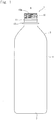
- the bottle has a mouth portion generally designated at 1 at its upper portion.
- the lower part of the mouth portion 1 stretches to a shoulder portion 3 that curves outward.
- the shoulder portion 3 stretches to a body portion 5, the lower end of the body portion 5 being closed with a bottom portion 7.
- a screw thread 10 is formed on the outer circumferential surface of the mouth portion 1 and with which a cap engages by screw.
- a circumferential protuberance 11 is formed under the screw thread 10.
- a TE band may be provided at the lower end of the cap that is fitted by screw. Engagement of the TE band with the circumferential protuberance 11 creates evidence of not still tampered. Namely, if the cap is opened, the TE band remains on the container side being separated away from the cap letting general consumers to know that the cap was once opened.
- a support ring 13 of a large diameter is formed at the lowermost par of the mouth portion 1 of the container.
- the container can be held and carried by utilizing the support ring 13.
- annular or arcuate horizontally recessed portion 17 is formed between the upper end 10a of the screw thread 10 and the upper end 15 of the container (bottle). That is, a side wall surface 19 stretches down in the vertical direction from the outer circumferential edge of the upper end 15 of the mouth portion, and is continuous, at a point X of intersection, to an upper wall surface 17a of the horizontally recessed portion 17.
- the upper wall surface 17a of the horizontally recessed portion 17 has an angle ⁇ of 90 to 150 degrees and, particularly preferably, 90 to 120 degrees relative to the vertical direction.
- the angle ⁇ lying within the above range, when the container is tilted to pour out the liquid contained therein, the liquid may flow down to the side wall surface 19 from the outer circumferential edge of the upper end 15 of the mouth portion as shown in Fig. 3 . In this case, however, the liquid is cut at the portion (point of intersection) X where the side wall surface 19 and the upper wall surface 17a of the horizontally recessed portion 17 are joined together and at where the force that pushes the liquid against the wall becomes zero.
- the liquid separates away from the container wall and falls down separating away from the mouth portion 1 of the container.
- the liquid drips most at the start of pouring out the liquid in a state where the container is nearly standing upright or, concretely, at the start or at the end of pouring out the liquid contained therein.
- the recessed portion 17 is horizontal and does not work as a screw thread.
- the angle ⁇ of intersection is smaller than the above range, it becomes difficult to remove the metal mold at the time of forming. Concretely, if the angle ⁇ of intersection is smaller than 80 degrees, it becomes difficult to remove the metal mold even by such means as forced removal or after-treatment. Further, if the angle ⁇ is larger than the above range, the side wall surface 19 becomes continuous to the horizontally recessed portion 17 (ceiling wall 17a) so mildly that the liquid is not cut at the point X of intersection. The same also holds true when there is formed no horizontally recessed portion 17; i.e., there is no point X of intersection for cutting the liquid (i. e. , the liquid is not cut).
- the liquid drips down from the side wall surface 19 along the screw thread 10 like the bottle shown in Fig. 4 .
- the liquid that has dripped down further, creeps down along the outer surface of the bottle body portion 5 to foul the entire bottle.
- the horizontally recessed portion 17 is of an annular or arcuate shape. That is, the horizontally recessed portion 17 is formed over the whole circumference along the outer circumferential surface of the mouth portion 1 (annular recessed portion) or is formed intermittently along the outer circumferential surface of the mouth portion 1 (arcuate recessed portion).
- the horizontally recessed portion 17 of which shape be selected is suitably determined depending on the shape and use of the container. If the container of the invention is a round-shaped bottle, for example, there is no restriction on the direction in which the liquid content is to be poured out. In this case, therefore, the annular horizontally recessed portion 17 must be formed over the whole circumference along the outer circumferential surface of the mouth portion 1.
- the container of the invention is a square-shaped container as shown in Fig. 5 and, specifically, if the container is the square-shaped container having groove portions for gripping formed in the opposing two surfaces of the container body portion, the directions for pouring out the liquid have been specified. Therefore, the horizontally recessed portion 17 formed in the mouth portion 1 does not have to be of an annular shape; i.e., there may be formed one or a plurality of arcuate horizontally recessed portions 17 intermittently so as to be in parallel relative to the side surface of the container body portion 5.
- the container of the present invention should have a shape which is as sharp as possible at the point X of intersection. For instance, it is desired that the radius of curvature thereof is not more than 0.5 mm. When chamfered at the point X of intersection, it is desired that the chamfering C is as small as possible. If the point X of intersection is rounded in a large size, the liquid remaining on the sidewall surface 19 is not cut at the point X of intersection at the end of pouring the liquid but flows around to the inside of the horizontally recessed portion 17. It is, therefore, probable that the liquid may flow down to the portion where the screw thread 10 is formed passing through the horizontally recessed portion 17.
- the horizontally recessed portion 17 is formed at a position as close to the upper end 15 of the mouth portion as possible so far as the sealing is not lost when the cap is fitted.
- a distance L from the point X of intersection to the upper end 15 of the mouth portion is in a range of 1.0 to 2.0 mm. If the horizontally recessed portion 17 is formed at a too low position, the liquid remains in an increased amount on the side wall surface 19 when pouring the liquid is discontinued and flows around into the horizontally recessed portion 17. As a result, the liquid easily flows through the horizontally recessed portion 17 down to the portion where the screw thread 10 is formed. Further, if the horizontally recessed portion 17 is formed too close to the upper end 15 of the mouth portion, the area decreases in the portion where the cap that is fitted comes into close contact thereto, and it becomes difficult to stably maintain the sealing.
- the distance from the point X of intersection to the lower surface of the horizontally recessed portion 17 is regarded to be the height h of the horizontally recessed portion
- the distance L is within the above-mentioned range and the screw thread is formed at a position which is not too low. Since the lower surface of the horizontally recessed portion 17 and the upper end 10a of the screw thread are formed integrally together as shown in Fig. 2 , the height h of the horizontally recessed portion becomes the distance of from the point X of intersection to the upper end 10a of the screw thread.
- the depth d of the horizontally recessed portion 17 is large to some extent so far as the mouth portion 1 of the container does not lose the strength. For instance, it is desired that the depth d is in a range of from 0.2 to 1.5 mm. If the horizontally recessed portion 17 is not sufficiently deep, there occurs the same phenomenon as that of when the horizontally recessed portion 17 is not formed. That is, if the liquid that has flown down along the side wall surface 19 flows around even by a small amount into the recessed portion 17, then the recessed portion 17 is readily filled up with the liquid that has flown therein.
- the liquid becomes the priming, and the liquid that has flown down along the side wall surface 19 does not cut at the point X of intersection but flows down to the portion where the screw thread 10 is formed. If the depth d is too large, on the other hand, the strength of the mouth portion 1 decreases at the portion where the horizontally recessed portion 17 is formed, and the mouth portion 1 tends to be easily broken.
- the outer circumferential edge (portion that connects to the side wall surface 19) Y of the upper end 15 of the mouth portion has an angular shape close to the right angle like the above-mentioned point X of intersection.
- this portion comes into close contact with the inner surface of the cap that is fitted to the mouth portion, affects the sealing and may, further, come in contact with the mouth of a person who attempts to drink. Therefore, this portion Y may have a curved surface that is rounded to a suitable degree like the known containers. This is because, according to the present invention, the liquid is effectively prevented from dripping due to the formation of the above-mentioned horizontally recessed portion 17.
- Figs. 1 to 5 are concerned to the example of when the horizontally recessed portion is formed between the upper end of the screw thread and the upper end of the mouth portion.
- the effect of preventing the dripping of liquid may be also exhibited even by forming the horizontally recessed portion in the screw thread.
- the angle ⁇ of intersection of the upper wall surface of the horizontally recessed portion relative to the vertical direction is 90 to 150 degrees and, particularly preferably, 90 to 120 degrees.
- Figs. 1 to 6 are illustrating examples of a plastic bottle. So far as the mouth portion provided with the screw thread is formed, however, the mode of the container of the invention is not limited to the bottles only but can also be applied to the bottle-shaped containers having wide mouths and to the bag-shaped contains. There is no specific limitation on the shapes of the containers of the invention, either.
- the material of the container of the invention is not limited to the plastic material but may be a glass or a metal.
- the plastic material is desired from such a standpoint that the horizontally recessed portion 17 can be easily formed satisfying the above-mentioned conditions.
- the present invention improves the anti-dripping of liquid relying on the shape of the mouth portion of the container and, therefore, is not to specify or limit the contact angle between the mouth portion of the container and the liquid contained therein.
- the anti-dripping is not limited by the viscosity or surface tension of the liquid that is contained.
- plastic material there can be used those materials that have heretofore been used for producing containers for containing, specifically, liquids, such as polyesters as represented by polyethylene terephthalate (PET), and polyolefins like polyethylene and polypropylene. It is also possible to employ multilayer structures by using a gas-barrier resin such as ethylene vinyl alcohol resin or an oxygen absorber (oxidizing resin or transition metal catalyst) in combination with the above resin.
- a gas-barrier resin such as ethylene vinyl alcohol resin or an oxygen absorber (oxidizing resin or transition metal catalyst) in combination with the above resin.
- the liquid to be contained there can be selected any of those having low viscosities through up to those having high viscosities without special limitation. That is, the carbonated beverages have carbonic acid dissolved therein and are filled maintaining head space of some volume whereas the non-carbonated beverages are nearly fully filled without leaving head space.
- the container is slightly tilted (the container is nearly upright) to pour out the liquid; i.e., the liquid is very likely to drip down.
- the present invention makes it possible to effectively prevent the liquid from dripping even at the start of pouring out the non- carbonated beverage.
- the mouth portions of the containers are formed white due to the heat crystallization for imparting heat resistance.
- the liquids that are contained are colored liquids such as coffee, soy sauce, or various kinds of juices, fouling of the mouth portion of the container appears very conspicuous due to the liquid that has dripped.
- the present invention is very useful in effectively preventing the liquid from dripping.
- the present invention is applied to the bottles having volumes of not less than 500 ml. Namely, in the case of beverage bottles of small volumes of about 180 ml, the consumers, in many cases, drink the contents directly from the mouth portion of the containers. As the volumes of the containers increase, however, the consumes drink the liquid contents by once transferring them into a cup inviting, therefore, the occurrence of liquid dripping. It is, therefore, also effective to apply the present invention to the beverage bottles of large volumes.
- PET bottles of a volume of 500 ml were used as sample bottles by changing only the mouth portion that formed the screw thread.
- the bottles were each filled with 498 ml of coffee ⁇ viscosity at 25°C: 10 mPaS (B-type viscometer) ⁇ as the liquid content.
- the positions of the center of gravity and the tilted angles were recorded as data every time based on the human operation for pouring out the liquid by hand.
- a jig (6-axis-controlled robot manufactured by Yasukawa Denki Co.)
- each of the samples was moved and turned to observe the state of liquid dripping with the eye.
- the samples that permitted the liquid to fall down to the portion where the screw thread was formed were evaluated to be ⁇ (poor) and the samples that have cut the liquid at the point X of intersection were evaluated to be ⁇ (good).
- the specifications of the mouth portion were set as described below.
- Example 1 was followed but changing the specifications of the mouth portion as follows: Angle ⁇ intersected by the horizontally recessed portion 17 and the side wall surface 19: 150 degrees
- Example 1 was followed but changing the specifications of the mouth portion as follows: Distance L between the point X of intersection and the mouth portion 15: 2.00 mm
- Example 1 was followed but changing the specifications of the mouth portion as follows: Distance L between the point X of intersection and the mouth portion 15: 1.00 mm
- Example 1 was followed but changing the specifications of the mouth portion as follows: Radius R of curvature at the point X of intersection: 0.5
- Example 1 was followed but changing the specifications of the mouth portion as follows: Chamfer C at the point X of intersection: 0.3
- Example 1 was followed but changing the specifications of the mouth portion as follows: Depth d of the horizontally recessed portion 17: 0.2 mm
- Example 1 was followed but changing the specifications of the mouth portion as follows: Depth d of the horizontally recessed portion 17: 1.5 mm
- Example 1 was followed but changing the specifications of the mouth portion as follows: Angle ⁇ intersected by the horizontally recessed portion 17 and the side wall surface 19: 86 degrees
- Example 1 was followed but changing the specifications of the mouth portion as follows: Angle ⁇ intersected by the horizontally recessed portion 17 and the side wall surface 19: 160 degrees
- Table 1 shows the results of testing the liquid drip prevention by using the sample bottles having the above-mentioned mouth portions.
- Table 1 Example Comp. Example Item 1 2 3 4 5 6 7 8 9 1 2 Intersec ting angle ⁇ Radius of curvature or 120 150 120 120 120 120 120 120 120 86 - 160 chamfer at point X R0.1 R0.1 R0.1 R0.1 R0.5 C0.3 R0.1 R0.1 R0.1 - R0.1 Distance L (mm) 1.25 1.25 2.0 1.0 1.25 1.25 1.25 1.25 1.25 1.25 1.25 - 1.25 Depth d (mm) 1.0 1.0 1.0 1.0 1.0 1.0 1.0 1.0 0.2 1.5 1.0 - 1.0 No dripping ⁇ ⁇ ⁇ ⁇ ⁇ ⁇ ⁇ ⁇ ⁇ ⁇ ⁇ ⁇ ⁇ ⁇ ⁇ ⁇ ⁇ ⁇
Landscapes
- Engineering & Computer Science (AREA)
- Mechanical Engineering (AREA)
- Ceramic Engineering (AREA)
- Containers Having Bodies Formed In One Piece (AREA)
- Closures For Containers (AREA)
- Details Of Rigid Or Semi-Rigid Containers (AREA)
Claims (7)
- Ein Behälter, dessen Mündungsabschnitt (1) an der äußeren Umfangsfläche davon ein Schraubgewinde (10) zur Befestigung einer Kappe bildet,
wobei ein horizontal vertiefter Abschnitt (17), der bogen- oder winkelförmig ist, zwischen einem oberen Ende (10a) des genannten Schraubgewindes (10) und einem oberen Ende (15) des genannten Mündungsabschnitts (1) gebildet wird,
wobei der genannte horizontal vertiefte Abschnitt eine obere Wandfläche (17a) aufweist, die die Außenwand des Mündungsabschnitts an einem Punkt X und einer unteren Wandfläche schneidet,
wobei ein Winkel θ der oberen Wandfläche (17a) des genannten horizontal vertieften Abschnitts (17) auf 90° bis 150° in Bezug auf die vertikale Richtung eingestellt ist, dadurch gekennzeichnet, dass
die untere Wandfläche des horizontal vertieften Abschnitts (17) und das obere Ende (10a) des Schraubgewindes (10) einstückig ausgebildet sind, d. h. dass der Abstand ausgehend vom Punkt X bis zur unteren Wandfläche des horizontal vertieften Abschnitts (17) dem Abstand ausgehend vom Punkt X bis zum oberen Ende (10a) des Schraubgewindes gleicht. - Der Behälter nach Anspruch 1, wobei der genannte horizontal vertiefte Abschnitt (17) eine ringförmige Gestalt aufweist.
- Der Behälter nach Anspruch 1, wobei der Abstand L ausgehend von der oberen Wandfläche (17a) des genannten horizontal vertieften Abschnitts (17) bis zum oberen Ende (15) des genannten Mündungsabschnitts (1) in einem Bereich zwischen 1 und 2 mm liegt.
- Der Behälter nach Anspruch 1, wobei die Tiefe d des genannten horizontal vertieften Abschnitts (17) in einem Bereich zwischen 0,2 und 1,5 mm liegt.
- Der Behälter nach Anspruch 1, wobei der genannte Behälter aus einem Kunststoffmaterial hergestellt wird.
- Der Behälter nach Anspruch 5, wobei der genannte Behälter zur Aufnahme von kohlensäurefreien Getränken verwendet wird.
- Der Behälter nach Anspruch 5, wobei der genannte Behälter einen Mündungsabschnitt (1) aufweist, der in weißer Farbe gebildet wird, und zur Aufnahme von farbigen Flüssigkeiten verwendet wird.
Applications Claiming Priority (2)
| Application Number | Priority Date | Filing Date | Title |
|---|---|---|---|
| JP2011163144 | 2011-07-26 | ||
| PCT/JP2012/063592 WO2013015006A1 (ja) | 2011-07-26 | 2012-05-28 | 液垂れ防止性に優れた容器 |
Publications (3)
| Publication Number | Publication Date |
|---|---|
| EP2738112A1 EP2738112A1 (de) | 2014-06-04 |
| EP2738112A4 EP2738112A4 (de) | 2015-03-18 |
| EP2738112B1 true EP2738112B1 (de) | 2017-03-01 |
Family
ID=47600866
Family Applications (1)
| Application Number | Title | Priority Date | Filing Date |
|---|---|---|---|
| EP12818230.0A Not-in-force EP2738112B1 (de) | 2011-07-26 | 2012-05-28 | Tropfvermeindender Behälter |
Country Status (6)
| Country | Link |
|---|---|
| US (1) | US20140166607A1 (de) |
| EP (1) | EP2738112B1 (de) |
| JP (1) | JP6070556B2 (de) |
| KR (1) | KR20140042910A (de) |
| CN (1) | CN103826977A (de) |
| WO (1) | WO2013015006A1 (de) |
Families Citing this family (9)
| Publication number | Priority date | Publication date | Assignee | Title |
|---|---|---|---|---|
| JP3774843B2 (ja) * | 2001-05-25 | 2006-05-17 | マルヤス工業株式会社 | 多管式熱交換器 |
| JP4860531B2 (ja) * | 2007-03-30 | 2012-01-25 | 株式会社クボタ | 熱分解管 |
| GB2485399B (en) * | 2010-11-12 | 2014-02-12 | Mark Harrison | Container preventing contact with plastics |
| US9114911B2 (en) * | 2012-10-19 | 2015-08-25 | Owens-Brockway Glass Container Inc. | Container, handle for a container, and handle and container assembly |
| US20160137346A1 (en) | 2014-11-18 | 2016-05-19 | Brandeis University | Drip free glass bottles and methods of making such bottles |
| EP3458372B1 (de) * | 2016-05-17 | 2025-11-26 | Brandeis University | Tropffreie glasflaschen mit umlaufendem kanal sowie verfahren zur herstellung und verwendung solcher flaschen |
| KR20220151685A (ko) | 2020-03-23 | 2022-11-15 | 엔.이. 켐캣 가부시키가이샤 | 전극용 촉매의 제조 시스템 및 제조 방법 |
| USD976109S1 (en) * | 2021-05-21 | 2023-01-24 | The Clorox Company | Bottle |
| EP4680418A1 (de) | 2023-03-17 | 2026-01-21 | Belvac Production Machinery, Inc. | Metallbehälter mit tragring und verfahren zur herstellung davon |
Family Cites Families (29)
| Publication number | Priority date | Publication date | Assignee | Title |
|---|---|---|---|---|
| US2025406A (en) * | 1932-11-04 | 1935-12-24 | Richard B Tippett | Nondrip bottle |
| US2014033A (en) * | 1933-07-27 | 1935-09-10 | Seneca S Smith | Bottle and seal therefor |
| US2708049A (en) * | 1952-03-05 | 1955-05-10 | Sokolik Edward | Bottle for liquid dairy products |
| US2854163A (en) * | 1954-04-09 | 1958-09-30 | Owens Illinois Glass Co | Pour-out fitments |
| US2785841A (en) * | 1954-12-22 | 1957-03-19 | French Co R T | Non-drip controllable-flow bottle and closure |
| US3086671A (en) * | 1962-08-17 | 1963-04-23 | Hyspect Container Corp | Plastic bottle |
| US3297184A (en) * | 1963-11-05 | 1967-01-10 | B D Lab Inc | Cap for culture tubes |
| US3804285A (en) * | 1972-05-23 | 1974-04-16 | Lilly Co Eli | Bottle with pourout neck |
| GB8725738D0 (en) * | 1987-11-03 | 1987-12-09 | Reliance Products Ltd | Cover for plastic containers |
| WO1989007553A1 (fr) * | 1988-02-19 | 1989-08-24 | Stölzle-Oberglas Aktiengesellschaft | Embouchure de recipient pour matiere coulante |
| US5050754A (en) * | 1989-10-23 | 1991-09-24 | West Penn Plastics, Inc. | Cap for a neck finish on a wide mouth container |
| GB2257693B (en) * | 1991-07-10 | 1995-08-02 | Beeson & Sons Ltd | A container and closure |
| GB9012041D0 (en) * | 1990-05-30 | 1990-07-18 | Beeson & Sons Ltd | Improvements in or relating to containers |
| US5150803A (en) * | 1991-07-25 | 1992-09-29 | Mr. Coffee, Inc. | Decanter and lid assembly for automatic drip coffee maker |
| BE1006399A7 (nl) * | 1993-09-27 | 1994-08-16 | Resilux | Afsluitinrichting. |
| RU2129975C1 (ru) * | 1995-03-06 | 1999-05-10 | Продакт Инвестмент, Инк. | Укупорочное устройство с индикацией вскрытия |
| US5553727C1 (en) * | 1995-04-27 | 2001-09-04 | Rical Sa | Tamper-evident cap and neck finish |
| JPH09193937A (ja) | 1996-01-18 | 1997-07-29 | Kikkoman Corp | 液体包装用瓶 |
| DE19645263A1 (de) * | 1996-11-02 | 1998-05-07 | Tetra Laval Holdings & Finance | Fließmittelpackung mit aseptisch dichtem Schnappdeckel und Vorformling zur Herstellung dieser Packung |
| US6264050B1 (en) * | 1998-10-06 | 2001-07-24 | Plastipak Packaging, Inc. | Container with improved neck portion and method for making the same |
| JP2001097384A (ja) | 1999-09-27 | 2001-04-10 | Toyo Glass Co Ltd | ガラス容器 |
| FR2800357B1 (fr) * | 1999-11-03 | 2002-01-04 | Pechiney Emballage Alimentaire | Verseur ameliore et capsule a verseur incorpore |
| USD463982S1 (en) * | 2001-08-15 | 2002-10-08 | Silgan Plastics Corporation | Container |
| JP3994146B2 (ja) * | 2001-12-18 | 2007-10-17 | 株式会社吉野工業所 | 合成樹脂製容器本体およびプリフォームの金型装置 |
| US6997336B2 (en) * | 2002-09-23 | 2006-02-14 | Graham Packaging Company, L.P. | Plastic cafare |
| CN101172529A (zh) * | 2007-08-30 | 2008-05-07 | 宋孟光 | 一种有槽口可回流的防滴漏瓶口 |
| FR2946960B1 (fr) * | 2009-06-19 | 2016-07-01 | Presticorc | Coiffe du type a emmanchement pour bouteille et la bouteille equipee d'une telle coiffe |
| CH703187A1 (de) * | 2010-05-27 | 2011-11-30 | Bottletec Gmbh | Behälter mit Verschlussgewinde. |
| US9016489B2 (en) * | 2010-06-30 | 2015-04-28 | Amcor Limited | Circumferential reinforcing groove for container finish |
-
2012
- 2012-05-28 EP EP12818230.0A patent/EP2738112B1/de not_active Not-in-force
- 2012-05-28 CN CN201280046325.2A patent/CN103826977A/zh active Pending
- 2012-05-28 US US14/234,885 patent/US20140166607A1/en not_active Abandoned
- 2012-05-28 KR KR1020147004891A patent/KR20140042910A/ko not_active Ceased
- 2012-05-28 JP JP2013525607A patent/JP6070556B2/ja active Active
- 2012-05-28 WO PCT/JP2012/063592 patent/WO2013015006A1/ja not_active Ceased
Non-Patent Citations (1)
| Title |
|---|
| None * |
Also Published As
| Publication number | Publication date |
|---|---|
| EP2738112A4 (de) | 2015-03-18 |
| KR20140042910A (ko) | 2014-04-07 |
| EP2738112A1 (de) | 2014-06-04 |
| JP6070556B2 (ja) | 2017-02-01 |
| WO2013015006A1 (ja) | 2013-01-31 |
| JPWO2013015006A1 (ja) | 2015-02-23 |
| US20140166607A1 (en) | 2014-06-19 |
| CN103826977A (zh) | 2014-05-28 |
Similar Documents
| Publication | Publication Date | Title |
|---|---|---|
| EP2738112B1 (de) | Tropfvermeindender Behälter | |
| RU2562501C2 (ru) | Стеклянный контейнер с горлышком, имеющим внутреннюю резьбу | |
| CA3008894C (en) | Closure with angled plug seal | |
| US20080257849A1 (en) | Container with Securement for a Cap | |
| EP3347282B1 (de) | Leichter polymerbehälter | |
| US10633150B2 (en) | Pour spout device | |
| CN1345687A (zh) | 饮料瓶 | |
| US20140225309A1 (en) | Plastic bottle | |
| NZ565698A (en) | Container closure assembly with cylindrical internal formation of cap forming seal with sealing member containing reservoir | |
| US8215506B2 (en) | Flip top closure assembly for a bottle | |
| WO2015013489A1 (en) | Bottle with expansion chamber and pinch grips | |
| AU2013363636A1 (en) | Bottle with bridge and fluid channel | |
| EP3458372B1 (de) | Tropffreie glasflaschen mit umlaufendem kanal sowie verfahren zur herstellung und verwendung solcher flaschen | |
| JP6885761B2 (ja) | 合成樹脂キャップ及びキャップユニット | |
| JP2013233986A (ja) | 液垂れ防止性に優れた包装体 | |
| CN210708308U (zh) | 一种金属螺旋口罐 | |
| WO2025165253A1 (en) | Sealing system for containers adapted for the transport and/or storage of liquids | |
| JP2014037257A (ja) | 液垂れ防止性が改善された容器 | |
| US12441525B1 (en) | Apparatus and method for closing a bottle with a flexible cylinder | |
| AU3440200A (en) | Plastic closure | |
| JP7822120B2 (ja) | 口栓部の構造、包装体、包装体の閉栓方法 | |
| EP1652777A1 (de) | Kunststoffflasche mit einem Behälterhals für einen mit Hebel zu öffnenden Aufdruckkronverschluß | |
| WO2025183226A1 (ja) | 液体容器 | |
| WO2011016753A1 (ru) | Венчик горловины бутылки | |
| JPH0513943U (ja) | 飲料缶用注出補助具 |
Legal Events
| Date | Code | Title | Description |
|---|---|---|---|
| PUAI | Public reference made under article 153(3) epc to a published international application that has entered the european phase |
Free format text: ORIGINAL CODE: 0009012 |
|
| 17P | Request for examination filed |
Effective date: 20140225 |
|
| AK | Designated contracting states |
Kind code of ref document: A1 Designated state(s): AL AT BE BG CH CY CZ DE DK EE ES FI FR GB GR HR HU IE IS IT LI LT LU LV MC MK MT NL NO PL PT RO RS SE SI SK SM TR |
|
| DAX | Request for extension of the european patent (deleted) | ||
| A4 | Supplementary search report drawn up and despatched |
Effective date: 20150213 |
|
| RIC1 | Information provided on ipc code assigned before grant |
Ipc: B65D 1/02 20060101ALI20150209BHEP Ipc: B65D 23/06 20060101AFI20150209BHEP |
|
| 17Q | First examination report despatched |
Effective date: 20151223 |
|
| GRAP | Despatch of communication of intention to grant a patent |
Free format text: ORIGINAL CODE: EPIDOSNIGR1 |
|
| INTG | Intention to grant announced |
Effective date: 20160915 |
|
| STAA | Information on the status of an ep patent application or granted ep patent |
Free format text: STATUS: GRANT OF PATENT IS INTENDED |
|
| GRAS | Grant fee paid |
Free format text: ORIGINAL CODE: EPIDOSNIGR3 |
|
| GRAA | (expected) grant |
Free format text: ORIGINAL CODE: 0009210 |
|
| STAA | Information on the status of an ep patent application or granted ep patent |
Free format text: STATUS: THE PATENT HAS BEEN GRANTED |
|
| AK | Designated contracting states |
Kind code of ref document: B1 Designated state(s): AL AT BE BG CH CY CZ DE DK EE ES FI FR GB GR HR HU IE IS IT LI LT LU LV MC MK MT NL NO PL PT RO RS SE SI SK SM TR |
|
| REG | Reference to a national code |
Ref country code: GB Ref legal event code: FG4D |
|
| REG | Reference to a national code |
Ref country code: CH Ref legal event code: EP Ref country code: AT Ref legal event code: REF Ref document number: 870982 Country of ref document: AT Kind code of ref document: T Effective date: 20170315 |
|
| REG | Reference to a national code |
Ref country code: IE Ref legal event code: FG4D |
|
| REG | Reference to a national code |
Ref country code: DE Ref legal event code: R096 Ref document number: 602012029353 Country of ref document: DE |
|
| REG | Reference to a national code |
Ref country code: FR Ref legal event code: PLFP Year of fee payment: 6 |
|
| REG | Reference to a national code |
Ref country code: NL Ref legal event code: MP Effective date: 20170301 |
|
| REG | Reference to a national code |
Ref country code: LT Ref legal event code: MG4D |
|
| REG | Reference to a national code |
Ref country code: AT Ref legal event code: MK05 Ref document number: 870982 Country of ref document: AT Kind code of ref document: T Effective date: 20170301 |
|
| PG25 | Lapsed in a contracting state [announced via postgrant information from national office to epo] |
Ref country code: GR Free format text: LAPSE BECAUSE OF FAILURE TO SUBMIT A TRANSLATION OF THE DESCRIPTION OR TO PAY THE FEE WITHIN THE PRESCRIBED TIME-LIMIT Effective date: 20170602 Ref country code: HR Free format text: LAPSE BECAUSE OF FAILURE TO SUBMIT A TRANSLATION OF THE DESCRIPTION OR TO PAY THE FEE WITHIN THE PRESCRIBED TIME-LIMIT Effective date: 20170301 Ref country code: FI Free format text: LAPSE BECAUSE OF FAILURE TO SUBMIT A TRANSLATION OF THE DESCRIPTION OR TO PAY THE FEE WITHIN THE PRESCRIBED TIME-LIMIT Effective date: 20170301 Ref country code: LT Free format text: LAPSE BECAUSE OF FAILURE TO SUBMIT A TRANSLATION OF THE DESCRIPTION OR TO PAY THE FEE WITHIN THE PRESCRIBED TIME-LIMIT Effective date: 20170301 Ref country code: NO Free format text: LAPSE BECAUSE OF FAILURE TO SUBMIT A TRANSLATION OF THE DESCRIPTION OR TO PAY THE FEE WITHIN THE PRESCRIBED TIME-LIMIT Effective date: 20170601 |
|
| PG25 | Lapsed in a contracting state [announced via postgrant information from national office to epo] |
Ref country code: AT Free format text: LAPSE BECAUSE OF FAILURE TO SUBMIT A TRANSLATION OF THE DESCRIPTION OR TO PAY THE FEE WITHIN THE PRESCRIBED TIME-LIMIT Effective date: 20170301 Ref country code: ES Free format text: LAPSE BECAUSE OF FAILURE TO SUBMIT A TRANSLATION OF THE DESCRIPTION OR TO PAY THE FEE WITHIN THE PRESCRIBED TIME-LIMIT Effective date: 20170301 Ref country code: BG Free format text: LAPSE BECAUSE OF FAILURE TO SUBMIT A TRANSLATION OF THE DESCRIPTION OR TO PAY THE FEE WITHIN THE PRESCRIBED TIME-LIMIT Effective date: 20170601 Ref country code: SE Free format text: LAPSE BECAUSE OF FAILURE TO SUBMIT A TRANSLATION OF THE DESCRIPTION OR TO PAY THE FEE WITHIN THE PRESCRIBED TIME-LIMIT Effective date: 20170301 Ref country code: RS Free format text: LAPSE BECAUSE OF FAILURE TO SUBMIT A TRANSLATION OF THE DESCRIPTION OR TO PAY THE FEE WITHIN THE PRESCRIBED TIME-LIMIT Effective date: 20170301 Ref country code: LV Free format text: LAPSE BECAUSE OF FAILURE TO SUBMIT A TRANSLATION OF THE DESCRIPTION OR TO PAY THE FEE WITHIN THE PRESCRIBED TIME-LIMIT Effective date: 20170301 Ref country code: LU Free format text: LAPSE BECAUSE OF NON-PAYMENT OF DUE FEES Effective date: 20170531 |
|
| PG25 | Lapsed in a contracting state [announced via postgrant information from national office to epo] |
Ref country code: NL Free format text: LAPSE BECAUSE OF FAILURE TO SUBMIT A TRANSLATION OF THE DESCRIPTION OR TO PAY THE FEE WITHIN THE PRESCRIBED TIME-LIMIT Effective date: 20170301 |
|
| PG25 | Lapsed in a contracting state [announced via postgrant information from national office to epo] |
Ref country code: EE Free format text: LAPSE BECAUSE OF FAILURE TO SUBMIT A TRANSLATION OF THE DESCRIPTION OR TO PAY THE FEE WITHIN THE PRESCRIBED TIME-LIMIT Effective date: 20170301 Ref country code: SK Free format text: LAPSE BECAUSE OF FAILURE TO SUBMIT A TRANSLATION OF THE DESCRIPTION OR TO PAY THE FEE WITHIN THE PRESCRIBED TIME-LIMIT Effective date: 20170301 Ref country code: RO Free format text: LAPSE BECAUSE OF FAILURE TO SUBMIT A TRANSLATION OF THE DESCRIPTION OR TO PAY THE FEE WITHIN THE PRESCRIBED TIME-LIMIT Effective date: 20170301 Ref country code: CZ Free format text: LAPSE BECAUSE OF FAILURE TO SUBMIT A TRANSLATION OF THE DESCRIPTION OR TO PAY THE FEE WITHIN THE PRESCRIBED TIME-LIMIT Effective date: 20170301 Ref country code: IT Free format text: LAPSE BECAUSE OF FAILURE TO SUBMIT A TRANSLATION OF THE DESCRIPTION OR TO PAY THE FEE WITHIN THE PRESCRIBED TIME-LIMIT Effective date: 20170301 |
|
| PG25 | Lapsed in a contracting state [announced via postgrant information from national office to epo] |
Ref country code: PL Free format text: LAPSE BECAUSE OF FAILURE TO SUBMIT A TRANSLATION OF THE DESCRIPTION OR TO PAY THE FEE WITHIN THE PRESCRIBED TIME-LIMIT Effective date: 20170301 Ref country code: PT Free format text: LAPSE BECAUSE OF FAILURE TO SUBMIT A TRANSLATION OF THE DESCRIPTION OR TO PAY THE FEE WITHIN THE PRESCRIBED TIME-LIMIT Effective date: 20170703 Ref country code: IS Free format text: LAPSE BECAUSE OF FAILURE TO SUBMIT A TRANSLATION OF THE DESCRIPTION OR TO PAY THE FEE WITHIN THE PRESCRIBED TIME-LIMIT Effective date: 20170701 Ref country code: SM Free format text: LAPSE BECAUSE OF FAILURE TO SUBMIT A TRANSLATION OF THE DESCRIPTION OR TO PAY THE FEE WITHIN THE PRESCRIBED TIME-LIMIT Effective date: 20170301 |
|
| REG | Reference to a national code |
Ref country code: DE Ref legal event code: R097 Ref document number: 602012029353 Country of ref document: DE |
|
| REG | Reference to a national code |
Ref country code: CH Ref legal event code: PL |
|
| PLBE | No opposition filed within time limit |
Free format text: ORIGINAL CODE: 0009261 |
|
| STAA | Information on the status of an ep patent application or granted ep patent |
Free format text: STATUS: NO OPPOSITION FILED WITHIN TIME LIMIT |
|
| PG25 | Lapsed in a contracting state [announced via postgrant information from national office to epo] |
Ref country code: DK Free format text: LAPSE BECAUSE OF FAILURE TO SUBMIT A TRANSLATION OF THE DESCRIPTION OR TO PAY THE FEE WITHIN THE PRESCRIBED TIME-LIMIT Effective date: 20170301 Ref country code: MC Free format text: LAPSE BECAUSE OF FAILURE TO SUBMIT A TRANSLATION OF THE DESCRIPTION OR TO PAY THE FEE WITHIN THE PRESCRIBED TIME-LIMIT Effective date: 20170301 |
|
| 26N | No opposition filed |
Effective date: 20171204 |
|
| REG | Reference to a national code |
Ref country code: IE Ref legal event code: MM4A |
|
| PG25 | Lapsed in a contracting state [announced via postgrant information from national office to epo] |
Ref country code: LI Free format text: LAPSE BECAUSE OF NON-PAYMENT OF DUE FEES Effective date: 20170531 Ref country code: SI Free format text: LAPSE BECAUSE OF FAILURE TO SUBMIT A TRANSLATION OF THE DESCRIPTION OR TO PAY THE FEE WITHIN THE PRESCRIBED TIME-LIMIT Effective date: 20170301 Ref country code: CH Free format text: LAPSE BECAUSE OF NON-PAYMENT OF DUE FEES Effective date: 20170531 |
|
| PG25 | Lapsed in a contracting state [announced via postgrant information from national office to epo] |
Ref country code: LU Free format text: LAPSE BECAUSE OF NON-PAYMENT OF DUE FEES Effective date: 20170528 |
|
| REG | Reference to a national code |
Ref country code: BE Ref legal event code: MM Effective date: 20170531 |
|
| PG25 | Lapsed in a contracting state [announced via postgrant information from national office to epo] |
Ref country code: IE Free format text: LAPSE BECAUSE OF NON-PAYMENT OF DUE FEES Effective date: 20170528 |
|
| REG | Reference to a national code |
Ref country code: FR Ref legal event code: PLFP Year of fee payment: 7 |
|
| PG25 | Lapsed in a contracting state [announced via postgrant information from national office to epo] |
Ref country code: BE Free format text: LAPSE BECAUSE OF NON-PAYMENT OF DUE FEES Effective date: 20170531 |
|
| PG25 | Lapsed in a contracting state [announced via postgrant information from national office to epo] |
Ref country code: MT Free format text: LAPSE BECAUSE OF NON-PAYMENT OF DUE FEES Effective date: 20170528 |
|
| PG25 | Lapsed in a contracting state [announced via postgrant information from national office to epo] |
Ref country code: HU Free format text: LAPSE BECAUSE OF FAILURE TO SUBMIT A TRANSLATION OF THE DESCRIPTION OR TO PAY THE FEE WITHIN THE PRESCRIBED TIME-LIMIT; INVALID AB INITIO Effective date: 20120528 |
|
| PGFP | Annual fee paid to national office [announced via postgrant information from national office to epo] |
Ref country code: DE Payment date: 20190521 Year of fee payment: 8 |
|
| PGFP | Annual fee paid to national office [announced via postgrant information from national office to epo] |
Ref country code: FR Payment date: 20190523 Year of fee payment: 8 |
|
| PG25 | Lapsed in a contracting state [announced via postgrant information from national office to epo] |
Ref country code: CY Free format text: LAPSE BECAUSE OF NON-PAYMENT OF DUE FEES Effective date: 20170301 |
|
| PGFP | Annual fee paid to national office [announced via postgrant information from national office to epo] |
Ref country code: GB Payment date: 20190521 Year of fee payment: 8 |
|
| PG25 | Lapsed in a contracting state [announced via postgrant information from national office to epo] |
Ref country code: MK Free format text: LAPSE BECAUSE OF FAILURE TO SUBMIT A TRANSLATION OF THE DESCRIPTION OR TO PAY THE FEE WITHIN THE PRESCRIBED TIME-LIMIT Effective date: 20170301 |
|
| PG25 | Lapsed in a contracting state [announced via postgrant information from national office to epo] |
Ref country code: TR Free format text: LAPSE BECAUSE OF FAILURE TO SUBMIT A TRANSLATION OF THE DESCRIPTION OR TO PAY THE FEE WITHIN THE PRESCRIBED TIME-LIMIT Effective date: 20170301 |
|
| PG25 | Lapsed in a contracting state [announced via postgrant information from national office to epo] |
Ref country code: AL Free format text: LAPSE BECAUSE OF FAILURE TO SUBMIT A TRANSLATION OF THE DESCRIPTION OR TO PAY THE FEE WITHIN THE PRESCRIBED TIME-LIMIT Effective date: 20170301 |
|
| REG | Reference to a national code |
Ref country code: DE Ref legal event code: R119 Ref document number: 602012029353 Country of ref document: DE |
|
| GBPC | Gb: european patent ceased through non-payment of renewal fee |
Effective date: 20200528 |
|
| PG25 | Lapsed in a contracting state [announced via postgrant information from national office to epo] |
Ref country code: GB Free format text: LAPSE BECAUSE OF NON-PAYMENT OF DUE FEES Effective date: 20200528 Ref country code: FR Free format text: LAPSE BECAUSE OF NON-PAYMENT OF DUE FEES Effective date: 20200531 |
|
| PG25 | Lapsed in a contracting state [announced via postgrant information from national office to epo] |
Ref country code: DE Free format text: LAPSE BECAUSE OF NON-PAYMENT OF DUE FEES Effective date: 20201201 |