EP2736769B1 - Befestigungsanordnung eines sensorelements an einem befestigungselement eines kraftwagens - Google Patents
Befestigungsanordnung eines sensorelements an einem befestigungselement eines kraftwagens Download PDFInfo
- Publication number
- EP2736769B1 EP2736769B1 EP12735780.4A EP12735780A EP2736769B1 EP 2736769 B1 EP2736769 B1 EP 2736769B1 EP 12735780 A EP12735780 A EP 12735780A EP 2736769 B1 EP2736769 B1 EP 2736769B1
- Authority
- EP
- European Patent Office
- Prior art keywords
- spring
- fastening
- region
- sensor
- sensor element
- Prior art date
- Legal status (The legal status is an assumption and is not a legal conclusion. Google has not performed a legal analysis and makes no representation as to the accuracy of the status listed.)
- Revoked
Links
- 239000007769 metal material Substances 0.000 claims description 3
- 239000000463 material Substances 0.000 claims description 2
- 230000004297 night vision Effects 0.000 description 35
- 238000004519 manufacturing process Methods 0.000 description 4
- 238000001514 detection method Methods 0.000 description 2
- 238000009434 installation Methods 0.000 description 2
- 230000010354 integration Effects 0.000 description 2
- 230000003287 optical effect Effects 0.000 description 2
- 230000002093 peripheral effect Effects 0.000 description 2
- 206010034972 Photosensitivity reaction Diseases 0.000 description 1
- 239000000654 additive Substances 0.000 description 1
- 230000000996 additive effect Effects 0.000 description 1
- 230000004888 barrier function Effects 0.000 description 1
- 238000011161 development Methods 0.000 description 1
- 230000018109 developmental process Effects 0.000 description 1
- 239000011521 glass Substances 0.000 description 1
- 238000002955 isolation Methods 0.000 description 1
- 230000013011 mating Effects 0.000 description 1
- 239000002184 metal Substances 0.000 description 1
- 230000036211 photosensitivity Effects 0.000 description 1
- XLYOFNOQVPJJNP-UHFFFAOYSA-N water Substances O XLYOFNOQVPJJNP-UHFFFAOYSA-N 0.000 description 1
Images


Classifications
-
- B—PERFORMING OPERATIONS; TRANSPORTING
- B60—VEHICLES IN GENERAL
- B60R—VEHICLES, VEHICLE FITTINGS, OR VEHICLE PARTS, NOT OTHERWISE PROVIDED FOR
- B60R11/00—Arrangements for holding or mounting articles, not otherwise provided for
- B60R11/04—Mounting of cameras operative during drive; Arrangement of controls thereof relative to the vehicle
-
- Y—GENERAL TAGGING OF NEW TECHNOLOGICAL DEVELOPMENTS; GENERAL TAGGING OF CROSS-SECTIONAL TECHNOLOGIES SPANNING OVER SEVERAL SECTIONS OF THE IPC; TECHNICAL SUBJECTS COVERED BY FORMER USPC CROSS-REFERENCE ART COLLECTIONS [XRACs] AND DIGESTS
- Y10—TECHNICAL SUBJECTS COVERED BY FORMER USPC
- Y10T—TECHNICAL SUBJECTS COVERED BY FORMER US CLASSIFICATION
- Y10T403/00—Joints and connections
- Y10T403/60—Biased catch or latch
- Y10T403/602—Biased catch or latch by separate spring
Definitions
- the invention relates to a mounting arrangement of a sensor element, in particular a camera, to a fastener of a motor vehicle according to the preamble of claim 1.
- the DE 10 2008 050 320 A1 discloses a support device for attachment to a disc, in particular a windshield, a motor vehicle according to the preamble of claim 1.
- the support device comprises a fastened to the disc support plate, which is at least partially made of a plastic and through which at least one camera, a sensor or the like is worn.
- the plastic of the carrier plate is mixed with an additional material, in particular with a glass additive.
- the support plate may comprise a support assembly having two upper support members and two lower support members against which the camera is to be urged with a unidirectional force. This force is generated by a spring arrangement with two spring elements. By means of the spring elements, the camera is pressed against reference surfaces of the support elements.
- the EP 1 810 896 A2 discloses a retaining clip for a sensor, comprising a plate which can cover the sensor, at least one retaining arm and at least one latching arm, which are adapted to engage a support frame for the sensor, wherein the retaining clip is integrally formed.
- the spring element has at least one second spring region extending at least indirectly adjoining the first spring region and extending at an angle to the first spring region, arranged between the fastening element and the sensor element, on which the sensor element slants in an oblique direction to the first direction, in particular perpendicular, extending second direction is supported, wherein the spring element is supported via the second spring portion in the second direction of the fastener and wherein the second spring portion at least indirectly indirectly abuts a sensor element facing and extending obliquely or perpendicular to the second direction surface of the fastener.
- the spring element allows with its two spring portions a multi-axis attachment of the sensor element to the fastener, since the spring with its two spring portions along a first axis, i. in the first direction, and along a second axis, i. can act in the second direction.
- the first spring region serves in particular for the purpose of fixing and fastening the sensor element to the retaining element relative to the fastening element, while the second spring region of the spring element serves as a support for the sensor element and, if appropriate, at the same time enables tolerance compensation, in particular as a result of production-related tolerances of the fastening element and / or of the sensor element.
- several functions are integrated in the one spring element. This functional integration keeps the number of parts of the mounting assembly low, which is associated with particularly low cost of the mounting arrangement. Furthermore, the low number of parts results in a particularly low weight of the fastening arrangement, which benefits a low weight of the motor vehicle designed, for example, as a passenger car.
- only one spring element is preferably provided, by means of which the sensor element is held on the fastening element. This keeps the number of parts, the cost and weight of the mounting arrangement according to the invention particularly low. In addition, this is a simple, time-consuming and cost-effective installation of the sensor element realized on the fastening element, since only one spring element is to be mounted.
- the holding element of the fastening element has a receptacle, in particular an undercut, into which the sensor element is held by means of the force caused by the spring element.
- the sensor element in particular a housing of this, preferably a receiving part, wherein advantageously an outer contour of the receiving part is at least partially formed as a receiving contour of the receptacle at least substantially corresponding mating contour.
- the sensor element is designed as a camera.
- This may be, for example, a so-called night vision camera, by means of which even at night to capture images and represent on at least one screen in a cockpit of the motor vehicle.
- the spring element is locked to the fastening element.
- the fastening element has at least one latching element with which the spring element is to be latched or clipped. This latching or clipping allows a particularly fast and thus time and cost-effective mounting of the sensor element to the fastener, which leads in particular in the context of mass production with a large number of pieces to significant cost savings.
- the spring element has a third spring region extending at least indirectly adjoining the first spring region and extending obliquely, in particular perpendicularly, to the first spring region, on which the sensor element is supported in the second direction, wherein the first spring region , in particular at least substantially centrally, is arranged between the second and the third spring region.
- the sensor element can be supported on both sides of the first spring region on the spring element, so that a particularly defined and in particular tilt-free mounting of the sensor element is realized on the fastening element. This is advantageous for the positioning of the sensor element relative to the fastening element and thus for the functional fulfillment of the sensor element, since this is defined in a defined manner relative to the fastening element and also relative to the rest of the motor vehicle.
- the spring element is supported on the fastening element via the third spring region in the second direction.
- the second and / or the third spring region is arranged between the fastening element and the sensor element, wherein the second and / or the third spring region at least indirectly on the surface of the fastening element facing the sensor element and inclined, in particular perpendicular, to the second direction is applied.
- the sensor element is aligned particularly precisely relative to the fastening element and thus to the rest of the motor vehicle. In particular, tolerances can be compensated for in a particularly advantageous manner.
- the sensor element is also held in the direction of the surface of the fastening element and thus optionally held against the second and / or third spring region, in particular pressed, while being subjected to the force of the spring element.
- the sensor element by means of the spring element, in particular by means of the first spring region, both in the first direction and in the second direction is acted upon by force, so that the sensor element is held particularly firmly and at the same time precisely on the fastening element.
- the spring element has a subsequent to the first spring portion and extending obliquely to the first spring portion handle portion, by means of which the spring element is manageable.
- the spring element is particularly simple, comfortable and therefore time-consuming and cost-effective to mount on this and to be dismantled from this about the oblique to the first spring region extending handle area.
- the spring element is formed in one piece, which keeps the number of parts, the weight and the cost of the fastening arrangement according to the invention particularly low.
- the fastener may be integrally formed, which also leads to a low number of parts, a low weight and low cost.
- the fastening element is formed from a plastic. This keeps the weight of the mounting assembly low, resulting in a particularly low weight of the motor vehicle.
- the spring element is at least substantially formed of a metallic material. This benefits the spring properties of the spring regions, which can be designed to be particularly elastic. Thus, the sensor element can be kept particularly firmly on the fastening element under a relatively high application of force.
- the invention also includes a mounting arrangement for a sensor element, in particular a camera, a motor vehicle, with a retaining element having a fastener and a spring element with a spring portion, by means of which a force oriented in one direction for holding the sensor element to the holding element can be generated.
- the spring element has a second spring region extending at least indirectly adjoining the first spring region and extending obliquely, in particular perpendicularly, to the first spring region, on which the sensor element can be supported in a second direction running obliquely or perpendicular to the first direction wherein the second spring portion is arranged in the state held on the fastening element of the sensor element between the latter and the fastening element and at least indirectly abuts a surface facing the sensor element and obliquely, in particular perpendicular, extending to the second direction surface of the fastener and wherein the spring element on the second spring portion in the second direction is supported on the fastener.
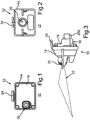
- the Fig. 1 shows a night vision camera 10 for a passenger car.
- the night-vision camera 10 is a camera module, which comprises a housing 12 with a first housing part 14 and a second housing part 16.
- the housing parts 14, 16 are connected to form a receiving space with each other, wherein in the receiving space electronic components of the night vision camera 10 are arranged in particular protected from water.
- a connector terminal 18 is arranged, via which the night-vision camera 10 is to be connected to a plug and above, for example, a vehicle electrical system and with a data bus of the passenger car.
- the night-vision camera 10 can be supplied with electrical energy and electrical signals. It is also possible to remove electrical signals from the night vision camera 10.
- a lens 20 is disposed on a front side of the night vision camera 10, via which light or light reflections can penetrate into the receiving space to optical detection means of the night vision camera 10.
- the night vision camera 10 or its optical detection means have a particularly high photosensitivity, so that they can capture images of the environment even in the dark and display on at least one screen in a cockpit of the passenger car. This benefits the driving safety, since the driver of the passenger car with the human eye is not or only with great difficulty can recognize recognizable elements such as passers-by, barriers and / or the like on the screen.
- the Fig. 3 shows the night-vision camera 10 in its side view, wherein a field of view 22 of the night-vision camera 10 is indicated. Furthermore, in the Fig. 3 to recognize a Steckerabgang 24, which illustrates how to connect the plug via the male connector 18 with the night-vision camera 10.
- a fastening bolt 24 of the night vision camera 10 can be seen, which is formed by the housing 12.
- the housing 12 and thus the fastening bolt 20 are formed for example of a plastic.
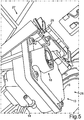
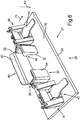
- the night-vision camera 10 can be attached to a fastening element 27 (FIG. Fig. 4 ) of the passenger car and thus be supported on the passenger car.
- the Fig. 4 to 7 show a mounting arrangement 28 of the night vision camera 10 on the at least substantially formed of a plastic fastener 27, which comprises a mounting plate 26. About the fastener 27, the night-vision camera 10 is held on the rest of the passenger car.
- the fastening bolt 24 is formed on the outer peripheral side out of round.
- an anti-rotation device is provided, so that the night vision camera 10 is defined and mounted at an angle to the fastening element 27 in a desired relative position to the mounting plate 26 and thus to the rest of the passenger car and not at least substantially in the vehicle transverse direction or at least substantially parallel to the longitudinal direction of the fastening bolt 24 extending axis of rotation can rotate.
- the fastening element 27 has a arranged on the mounting plate holding member 30 with a receptacle 32.
- the receptacle 32 is partially bounded by a first holding part 34 and partially by a second holding part 36 of the holding element 30.
- the holding parts 34, 36 are integrally formed with the mounting plate 26 of the plastic.
- the fastening bolt 24 is arranged in the mounting assembly 28 against rotation and angularly accurate in the receptacle 32 and is fixed by a force in the receptacle.
- the force is indicated by a first force arrow F1, extends in a first direction at least substantially parallel to the mounting plate 26 and is generated by means of a first spring portion 38 of a spring element 40 of the mounting assembly 28.
- a second spring region 42 of the spring element 40 adjoins the first spring region 38.
- a third spring region 44 of the spring element 40 adjoins the first spring region 38.
- the spring portions 38, 42, 44 are integrally formed with each other, wherein the spring element 40 is thus formed as a one-piece sheet metal component of a metallic material.
- a grip region 46 of the spring element 40 adjoins the first spring region 38 and extends at least essentially obliquely to the first spring region 38.
- the spring element 40 is particularly easy to handle and thus in a simple way with the fastener 27 to clasp and disassemble again from this.
- the first spring portion 38 is disposed between the spring portions 42, 44 and thus constitutes a central spring member, which fixes the fastening bolt 24, which is for example a front fastening bolt of the night vision camera 10 in the receptacle 32. That is, the first spring portion 38 presses the fastening bolt 24 in the first direction in the receptacle 32.
- the receptacle 32 has an undercut 48, so that the fastening bolt 24 and thus the night-vision camera 10 also in an at least substantially perpendicular to the mounting plate 26 extending second direction is held in the receptacle 32.
- the outside spring areas 42, 44 on both sides of the first spring area 38 serve the night-vision camera 10 as a support, so that the night-vision camera 10 is also held in the oblique, in particular perpendicular, to the first direction extending second direction by means of the spring element 40 on the fastening element 27.
- This second direction is indicated by a second force arrow F2 and extends at least substantially perpendicular to the mounting plate 26.
- the one hand, in support system with the housing 12 located spring portions 42, 44 are on the other hand with a night vision camera 10 facing surface 50 of the mounting plate 26 in support system and are used to compensate for example manufacturing tolerances. It is thus possible to align the night-vision camera 10 precisely and precisely relative to the fastening element 27 and thus to the rest of the passenger car so that its field of view 22 is advantageously oriented relative to the rest of the passenger car. This is the functional performance of the night vision camera 10 benefits.
- the spring element 40 due to its three spring portions 38, 42, 44 allows a multi-axis attachment of the night vision camera 10 to the fastener 27. It is possible to support the night-vision camera 10 exclusively by means of a spring element 40 on the fastening element 27.
- the described functional integration of the spring element 40 leads to a low number of parts and thus to a low weight and low cost of the fastening arrangement 28.
Landscapes
- Engineering & Computer Science (AREA)
- Mechanical Engineering (AREA)
- Fittings On The Vehicle Exterior For Carrying Loads, And Devices For Holding Or Mounting Articles (AREA)
- Studio Devices (AREA)
Applications Claiming Priority (2)
| Application Number | Priority Date | Filing Date | Title |
|---|---|---|---|
| DE102011108594A DE102011108594A1 (de) | 2011-07-26 | 2011-07-26 | Befestigungsanordnung eines Sensorelements an einem Befestigungselement eines Kraftwagens |
| PCT/EP2012/002653 WO2013013746A1 (de) | 2011-07-26 | 2012-06-23 | Befestigungsanordnung eines sensorelements an einem befestigungselement eines kraftwagens |
Publications (2)
| Publication Number | Publication Date |
|---|---|
| EP2736769A1 EP2736769A1 (de) | 2014-06-04 |
| EP2736769B1 true EP2736769B1 (de) | 2017-10-25 |
Family
ID=46516666
Family Applications (1)
| Application Number | Title | Priority Date | Filing Date |
|---|---|---|---|
| EP12735780.4A Revoked EP2736769B1 (de) | 2011-07-26 | 2012-06-23 | Befestigungsanordnung eines sensorelements an einem befestigungselement eines kraftwagens |
Country Status (6)
Cited By (1)
| Publication number | Priority date | Publication date | Assignee | Title |
|---|---|---|---|---|
| US10805509B2 (en) | 2016-09-01 | 2020-10-13 | Veoneer Sweden Ab | Imaging system for a motor vehicle |
Families Citing this family (8)
| Publication number | Priority date | Publication date | Assignee | Title |
|---|---|---|---|---|
| US10527523B2 (en) * | 2015-12-18 | 2020-01-07 | Ge Global Sourcing Llc | Vehicle sensor assembly having an RF sensor disposed in the sensor assembly to wirelessly communicate data to outside the sensor assembly |
| US10391523B2 (en) | 2016-09-16 | 2019-08-27 | Methode Electronics, Inc. | Sensor washing device |
| US10682988B2 (en) | 2016-09-16 | 2020-06-16 | Methode Electronics, Inc. | Enhanced washing device for vehicle accessory |
| US10422992B2 (en) | 2016-09-16 | 2019-09-24 | Methode Electronics, Inc. | Camera lens washing device |
| US10268038B2 (en) | 2016-09-16 | 2019-04-23 | Methode Electronics, Inc. | Camera lens washing device |
| DE102019108882A1 (de) | 2019-04-04 | 2020-10-08 | Valeo Schalter Und Sensoren Gmbh | Halterungsbasisteil zur Befestigung wenigstens eines Kameragehäuses an einem Fahrzeugteil eines Fahrzeugs, Kameragehäuse und Kamerasystem |
| US11571773B1 (en) | 2022-02-18 | 2023-02-07 | Ford Global Technologies, Llc | Vehicle sensor assembly |
| US12377790B2 (en) | 2022-05-25 | 2025-08-05 | Ford Global Technologies, Llc | Sensor assembly and method of installing to a vehicle |
Citations (6)
| Publication number | Priority date | Publication date | Assignee | Title |
|---|---|---|---|---|
| DE10256835A1 (de) | 2002-12-04 | 2004-06-24 | Alfred Engelmann Holding Gmbh | Innenspiegelanordnung für ein Kraftfahrzeug |
| EP1810896A2 (de) | 2006-01-19 | 2007-07-25 | TRW Automotive Electronics & Components GmbH & Co. KG | Halteklammer für einen Regensensor |
| US20070205348A1 (en) | 2004-03-26 | 2007-09-06 | Hans-Michael Schmitt | Retaining frame for a support element of a sensor |
| WO2008068573A2 (en) | 2006-12-05 | 2008-06-12 | Fico Mirrors, Sa | Wing rearview mirror with a camera or lightening device |
| DE102008050320A1 (de) | 2008-10-04 | 2010-04-08 | Daimler Ag | Trägervorrichtung zur Befestigung an einer Scheibe eines Kraftwagens |
| US20120099849A1 (en) | 2010-10-25 | 2012-04-26 | Honda Motor Co., Ltd. | Structure for mounting camera on vehicle |
Family Cites Families (12)
| Publication number | Priority date | Publication date | Assignee | Title |
|---|---|---|---|---|
| DE29924838U1 (de) | 1999-07-17 | 2006-01-12 | Robert Bosch Gmbh | Sensor zum optischen Erfassen von Fremdkörpern, insbesondere Regentropfen, auf einer Scheibe |
| DE50209654D1 (de) * | 2002-05-23 | 2007-04-19 | Swarovski Optik Kg | Stativkopf |
| JP2004076789A (ja) * | 2002-08-12 | 2004-03-11 | Ntn Corp | 車輪軸受装置の回転センサ取付構造 |
| US7077582B2 (en) * | 2003-08-20 | 2006-07-18 | Johnson Joseph M | Quick-release clamp for photographic equipment |
| DE102004032749B3 (de) | 2004-07-07 | 2006-01-05 | A. Raymond & Cie | Vorrichtung zum Befestigen eines Regensensors an einem Träger |
| US7374351B2 (en) * | 2005-08-10 | 2008-05-20 | Logitech Europe S.A. | Spring loaded attachment mechanism for camera and base |
| DE202006000853U1 (de) | 2006-01-19 | 2007-05-24 | Trw Automotive Electronics & Components Gmbh & Co. Kg | Halteklammer für einen Regensensor |
| DE202006017362U1 (de) | 2006-11-13 | 2008-03-20 | Trw Automotive Electronics & Components Gmbh & Co. Kg | Regensensor |
| JP4853720B2 (ja) | 2007-04-02 | 2012-01-11 | 株式会社ジェイテクト | 回転検出センサ取付構造 |
| DE102008044840A1 (de) | 2008-08-28 | 2010-03-04 | Leopold Kostal Gmbh & Co. Kg | Sensoranordnung für ein Kraftfahrzeug |
| DE102008044839A1 (de) * | 2008-08-28 | 2010-03-04 | Leopold Kostal Gmbh & Co. Kg | Sensoranordnung für ein Kraftfahrzeug |
| DE102012011596B3 (de) * | 2012-06-13 | 2013-07-04 | Decoma (Germany) Gmbh | Aufnahmevorrichtung |
-
2011
- 2011-07-26 DE DE102011108594A patent/DE102011108594A1/de not_active Withdrawn
-
2012
- 2012-06-23 CN CN201280036794.6A patent/CN103702868B/zh not_active Expired - Fee Related
- 2012-06-23 WO PCT/EP2012/002653 patent/WO2013013746A1/de active Application Filing
- 2012-06-23 US US14/234,787 patent/US9580023B2/en not_active Expired - Fee Related
- 2012-06-23 JP JP2014521966A patent/JP6305922B2/ja not_active Expired - Fee Related
- 2012-06-23 EP EP12735780.4A patent/EP2736769B1/de not_active Revoked
-
2017
- 2017-01-13 US US15/405,565 patent/US20170129420A1/en not_active Abandoned
Patent Citations (7)
| Publication number | Priority date | Publication date | Assignee | Title |
|---|---|---|---|---|
| DE10256835A1 (de) | 2002-12-04 | 2004-06-24 | Alfred Engelmann Holding Gmbh | Innenspiegelanordnung für ein Kraftfahrzeug |
| US20070205348A1 (en) | 2004-03-26 | 2007-09-06 | Hans-Michael Schmitt | Retaining frame for a support element of a sensor |
| EP1810896A2 (de) | 2006-01-19 | 2007-07-25 | TRW Automotive Electronics & Components GmbH & Co. KG | Halteklammer für einen Regensensor |
| DE102006040213A1 (de) | 2006-01-19 | 2007-08-02 | Trw Automotive Electronics & Components Gmbh & Co. Kg | Halteklammer für einen Regensensor |
| WO2008068573A2 (en) | 2006-12-05 | 2008-06-12 | Fico Mirrors, Sa | Wing rearview mirror with a camera or lightening device |
| DE102008050320A1 (de) | 2008-10-04 | 2010-04-08 | Daimler Ag | Trägervorrichtung zur Befestigung an einer Scheibe eines Kraftwagens |
| US20120099849A1 (en) | 2010-10-25 | 2012-04-26 | Honda Motor Co., Ltd. | Structure for mounting camera on vehicle |
Non-Patent Citations (1)
| Title |
|---|
| "Fahrzeugverglasung Kennzeichnung des Herstelldatums", VDA 261, August 1996 (1996-08-01), pages 1 - 2, XP055477709 |
Cited By (1)
| Publication number | Priority date | Publication date | Assignee | Title |
|---|---|---|---|---|
| US10805509B2 (en) | 2016-09-01 | 2020-10-13 | Veoneer Sweden Ab | Imaging system for a motor vehicle |
Also Published As
| Publication number | Publication date |
|---|---|
| EP2736769A1 (de) | 2014-06-04 |
| JP6305922B2 (ja) | 2018-04-04 |
| CN103702868B (zh) | 2016-01-13 |
| DE102011108594A1 (de) | 2013-01-31 |
| US9580023B2 (en) | 2017-02-28 |
| US20170129420A1 (en) | 2017-05-11 |
| JP2014521546A (ja) | 2014-08-28 |
| WO2013013746A1 (de) | 2013-01-31 |
| US20140169866A1 (en) | 2014-06-19 |
| CN103702868A (zh) | 2014-04-02 |
Similar Documents
| Publication | Publication Date | Title |
|---|---|---|
| EP2736769B1 (de) | Befestigungsanordnung eines sensorelements an einem befestigungselement eines kraftwagens | |
| DE102011121003A1 (de) | Trägervorrichtung zur Befestigung an einer Scheibe sowie Befestigungsanordnung einer Kamera oder dergleichen an einer solchen Trägervorrichtung | |
| EP2550556B1 (de) | Display-anordnung und deren montage | |
| DE102018213818A1 (de) | Halteeinrichtung für ein Außenanbauteil eines Kraftfahrzeugs | |
| EP1977127A1 (de) | Elektrische antriebseinheit, insbesondere elektromotor mit getriebe | |
| EP2539180B1 (de) | Halteeinrichtung zur halterung eines innenspiegelmoduls an einer windschutzscheibe | |
| DE10256835B4 (de) | Innenspiegelanordnung für ein Kraftfahrzeug | |
| WO2016150753A1 (de) | Linsenvorrichtung für einen optoelektronischen sensor eines kraftfahrzeugs mit befestigungseinrichtung, optoelektronischer sensor, kraftfahrzeug sowie verfahren | |
| DE102012024274A1 (de) | Halterungsvorrichtung zur Aufnahme und Befestigung eines Spiegels an einer Fahrzeugscheibe, Spiegeleinrichtung und Fahrzeug | |
| DE102020214539B4 (de) | Adapter, Radareinheit und Fahrzeug | |
| DE102012017942A1 (de) | Halteeinrichtung zum Halten einer Sensorvorrichtung an einer Scheibe eines Kraftfahrzeugs | |
| DE102015010295A1 (de) | Anzeigevorrichtung für ein Kraftfahrzeug | |
| EP1707440A2 (de) | Befestigung elektronischer Bauteile im Bereich der Windschutzscheibe eines Fahrzeuges | |
| DE102020004755B4 (de) | Haltesystem und Verwendung des Haltesystems | |
| DE10210383A1 (de) | Befestigungsfeder | |
| DE102017118893A1 (de) | Halterung, insbesondere für eine Anzeigevorrichtung eines Kraftfahrzeug | |
| DE102009010193A1 (de) | Stoßfängeranordnung | |
| DE102005050772A1 (de) | Elektromotor mit Befestigungsadapter | |
| DE102009058815A1 (de) | Haltevorrichtung für Anbauteile, insbesondere für Sonnenblenden, von Fahrzeugen | |
| DE102007050973B4 (de) | Vorrichtung und Verfahren zur Positionierung eines Sensors | |
| DE102016012673B4 (de) | Kraftfahrzeugspiegel | |
| DE102012024275A1 (de) | Befestigungsvorrichtung zum Befestigen von mechanischen, elektrischen und/oder elektronischen Modulen | |
| DE202010007737U1 (de) | Anordnung zur spaltfreien Montage von Karosserie-Anbauelementen eines Fahrzeuges | |
| DE102021133449A1 (de) | Erstes Gehäuseteil für ein Gehäuse für eine Vorrichtung für ein Fahrzeug, Gehäuse, Vorrichtung, Fahrzeug mit wenigstens einer Vorrichtung und Verfahren zur Montage einer Vorrichtung | |
| DE102023124679A1 (de) | Radarsystem für ein Fahrzeug sowie Fahrzeug |
Legal Events
| Date | Code | Title | Description |
|---|---|---|---|
| PUAI | Public reference made under article 153(3) epc to a published international application that has entered the european phase |
Free format text: ORIGINAL CODE: 0009012 |
|
| 17P | Request for examination filed |
Effective date: 20140111 |
|
| AK | Designated contracting states |
Kind code of ref document: A1 Designated state(s): AL AT BE BG CH CY CZ DE DK EE ES FI FR GB GR HR HU IE IS IT LI LT LU LV MC MK MT NL NO PL PT RO RS SE SI SK SM TR |
|
| DAX | Request for extension of the european patent (deleted) | ||
| 17Q | First examination report despatched |
Effective date: 20150521 |
|
| GRAP | Despatch of communication of intention to grant a patent |
Free format text: ORIGINAL CODE: EPIDOSNIGR1 |
|
| STAA | Information on the status of an ep patent application or granted ep patent |
Free format text: STATUS: GRANT OF PATENT IS INTENDED |
|
| INTG | Intention to grant announced |
Effective date: 20170515 |
|
| GRAS | Grant fee paid |
Free format text: ORIGINAL CODE: EPIDOSNIGR3 |
|
| GRAA | (expected) grant |
Free format text: ORIGINAL CODE: 0009210 |
|
| STAA | Information on the status of an ep patent application or granted ep patent |
Free format text: STATUS: THE PATENT HAS BEEN GRANTED |
|
| AK | Designated contracting states |
Kind code of ref document: B1 Designated state(s): AL AT BE BG CH CY CZ DE DK EE ES FI FR GB GR HR HU IE IS IT LI LT LU LV MC MK MT NL NO PL PT RO RS SE SI SK SM TR |
|
| REG | Reference to a national code |
Ref country code: GB Ref legal event code: FG4D Free format text: NOT ENGLISH |
|
| REG | Reference to a national code |
Ref country code: CH Ref legal event code: EP |
|
| REG | Reference to a national code |
Ref country code: AT Ref legal event code: REF Ref document number: 939605 Country of ref document: AT Kind code of ref document: T Effective date: 20171115 |
|
| REG | Reference to a national code |
Ref country code: IE Ref legal event code: FG4D Free format text: LANGUAGE OF EP DOCUMENT: GERMAN |
|
| REG | Reference to a national code |
Ref country code: DE Ref legal event code: R096 Ref document number: 502012011539 Country of ref document: DE |
|
| REG | Reference to a national code |
Ref country code: NL Ref legal event code: MP Effective date: 20171025 |
|
| REG | Reference to a national code |
Ref country code: LT Ref legal event code: MG4D |
|
| PG25 | Lapsed in a contracting state [announced via postgrant information from national office to epo] |
Ref country code: NL Free format text: LAPSE BECAUSE OF FAILURE TO SUBMIT A TRANSLATION OF THE DESCRIPTION OR TO PAY THE FEE WITHIN THE PRESCRIBED TIME-LIMIT Effective date: 20171025 |
|
| PG25 | Lapsed in a contracting state [announced via postgrant information from national office to epo] |
Ref country code: FI Free format text: LAPSE BECAUSE OF FAILURE TO SUBMIT A TRANSLATION OF THE DESCRIPTION OR TO PAY THE FEE WITHIN THE PRESCRIBED TIME-LIMIT Effective date: 20171025 Ref country code: SE Free format text: LAPSE BECAUSE OF FAILURE TO SUBMIT A TRANSLATION OF THE DESCRIPTION OR TO PAY THE FEE WITHIN THE PRESCRIBED TIME-LIMIT Effective date: 20171025 Ref country code: LT Free format text: LAPSE BECAUSE OF FAILURE TO SUBMIT A TRANSLATION OF THE DESCRIPTION OR TO PAY THE FEE WITHIN THE PRESCRIBED TIME-LIMIT Effective date: 20171025 Ref country code: NO Free format text: LAPSE BECAUSE OF FAILURE TO SUBMIT A TRANSLATION OF THE DESCRIPTION OR TO PAY THE FEE WITHIN THE PRESCRIBED TIME-LIMIT Effective date: 20180125 Ref country code: ES Free format text: LAPSE BECAUSE OF FAILURE TO SUBMIT A TRANSLATION OF THE DESCRIPTION OR TO PAY THE FEE WITHIN THE PRESCRIBED TIME-LIMIT Effective date: 20171025 |
|
| PG25 | Lapsed in a contracting state [announced via postgrant information from national office to epo] |
Ref country code: IS Free format text: LAPSE BECAUSE OF FAILURE TO SUBMIT A TRANSLATION OF THE DESCRIPTION OR TO PAY THE FEE WITHIN THE PRESCRIBED TIME-LIMIT Effective date: 20180225 Ref country code: HR Free format text: LAPSE BECAUSE OF FAILURE TO SUBMIT A TRANSLATION OF THE DESCRIPTION OR TO PAY THE FEE WITHIN THE PRESCRIBED TIME-LIMIT Effective date: 20171025 Ref country code: BG Free format text: LAPSE BECAUSE OF FAILURE TO SUBMIT A TRANSLATION OF THE DESCRIPTION OR TO PAY THE FEE WITHIN THE PRESCRIBED TIME-LIMIT Effective date: 20180125 Ref country code: RS Free format text: LAPSE BECAUSE OF FAILURE TO SUBMIT A TRANSLATION OF THE DESCRIPTION OR TO PAY THE FEE WITHIN THE PRESCRIBED TIME-LIMIT Effective date: 20171025 Ref country code: GR Free format text: LAPSE BECAUSE OF FAILURE TO SUBMIT A TRANSLATION OF THE DESCRIPTION OR TO PAY THE FEE WITHIN THE PRESCRIBED TIME-LIMIT Effective date: 20180126 Ref country code: LV Free format text: LAPSE BECAUSE OF FAILURE TO SUBMIT A TRANSLATION OF THE DESCRIPTION OR TO PAY THE FEE WITHIN THE PRESCRIBED TIME-LIMIT Effective date: 20171025 |
|
| REG | Reference to a national code |
Ref country code: FR Ref legal event code: PLFP Year of fee payment: 7 |
|
| REG | Reference to a national code |
Ref country code: DE Ref legal event code: R026 Ref document number: 502012011539 Country of ref document: DE |
|
| PLBI | Opposition filed |
Free format text: ORIGINAL CODE: 0009260 |
|
| PG25 | Lapsed in a contracting state [announced via postgrant information from national office to epo] |
Ref country code: SK Free format text: LAPSE BECAUSE OF FAILURE TO SUBMIT A TRANSLATION OF THE DESCRIPTION OR TO PAY THE FEE WITHIN THE PRESCRIBED TIME-LIMIT Effective date: 20171025 Ref country code: DK Free format text: LAPSE BECAUSE OF FAILURE TO SUBMIT A TRANSLATION OF THE DESCRIPTION OR TO PAY THE FEE WITHIN THE PRESCRIBED TIME-LIMIT Effective date: 20171025 Ref country code: EE Free format text: LAPSE BECAUSE OF FAILURE TO SUBMIT A TRANSLATION OF THE DESCRIPTION OR TO PAY THE FEE WITHIN THE PRESCRIBED TIME-LIMIT Effective date: 20171025 Ref country code: CY Free format text: LAPSE BECAUSE OF FAILURE TO SUBMIT A TRANSLATION OF THE DESCRIPTION OR TO PAY THE FEE WITHIN THE PRESCRIBED TIME-LIMIT Effective date: 20171025 Ref country code: CZ Free format text: LAPSE BECAUSE OF FAILURE TO SUBMIT A TRANSLATION OF THE DESCRIPTION OR TO PAY THE FEE WITHIN THE PRESCRIBED TIME-LIMIT Effective date: 20171025 |
|
| PLAX | Notice of opposition and request to file observation + time limit sent |
Free format text: ORIGINAL CODE: EPIDOSNOBS2 |
|
| 26 | Opposition filed |
Opponent name: PMA/TOOLS AG Effective date: 20180719 |
|
| PG25 | Lapsed in a contracting state [announced via postgrant information from national office to epo] |
Ref country code: IT Free format text: LAPSE BECAUSE OF FAILURE TO SUBMIT A TRANSLATION OF THE DESCRIPTION OR TO PAY THE FEE WITHIN THE PRESCRIBED TIME-LIMIT Effective date: 20171025 Ref country code: PL Free format text: LAPSE BECAUSE OF FAILURE TO SUBMIT A TRANSLATION OF THE DESCRIPTION OR TO PAY THE FEE WITHIN THE PRESCRIBED TIME-LIMIT Effective date: 20171025 Ref country code: SM Free format text: LAPSE BECAUSE OF FAILURE TO SUBMIT A TRANSLATION OF THE DESCRIPTION OR TO PAY THE FEE WITHIN THE PRESCRIBED TIME-LIMIT Effective date: 20171025 Ref country code: RO Free format text: LAPSE BECAUSE OF FAILURE TO SUBMIT A TRANSLATION OF THE DESCRIPTION OR TO PAY THE FEE WITHIN THE PRESCRIBED TIME-LIMIT Effective date: 20171025 |
|
| PGFP | Annual fee paid to national office [announced via postgrant information from national office to epo] |
Ref country code: BE Payment date: 20180628 Year of fee payment: 7 Ref country code: FR Payment date: 20180629 Year of fee payment: 7 |
|
| PG25 | Lapsed in a contracting state [announced via postgrant information from national office to epo] |
Ref country code: MT Free format text: LAPSE BECAUSE OF FAILURE TO SUBMIT A TRANSLATION OF THE DESCRIPTION OR TO PAY THE FEE WITHIN THE PRESCRIBED TIME-LIMIT Effective date: 20171025 |
|
| PGFP | Annual fee paid to national office [announced via postgrant information from national office to epo] |
Ref country code: DE Payment date: 20180831 Year of fee payment: 7 Ref country code: GB Payment date: 20180629 Year of fee payment: 7 |
|
| PG25 | Lapsed in a contracting state [announced via postgrant information from national office to epo] |
Ref country code: SI Free format text: LAPSE BECAUSE OF FAILURE TO SUBMIT A TRANSLATION OF THE DESCRIPTION OR TO PAY THE FEE WITHIN THE PRESCRIBED TIME-LIMIT Effective date: 20171025 |
|
| PLBB | Reply of patent proprietor to notice(s) of opposition received |
Free format text: ORIGINAL CODE: EPIDOSNOBS3 |
|
| RDAF | Communication despatched that patent is revoked |
Free format text: ORIGINAL CODE: EPIDOSNREV1 |
|
| REG | Reference to a national code |
Ref country code: DE Ref legal event code: R064 Ref document number: 502012011539 Country of ref document: DE Ref country code: DE Ref legal event code: R103 Ref document number: 502012011539 Country of ref document: DE |
|
| REG | Reference to a national code |
Ref country code: CH Ref legal event code: PL |
|
| REG | Reference to a national code |
Ref country code: IE Ref legal event code: MM4A |
|
| PG25 | Lapsed in a contracting state [announced via postgrant information from national office to epo] |
Ref country code: LU Free format text: LAPSE BECAUSE OF NON-PAYMENT OF DUE FEES Effective date: 20180623 Ref country code: MC Free format text: LAPSE BECAUSE OF FAILURE TO SUBMIT A TRANSLATION OF THE DESCRIPTION OR TO PAY THE FEE WITHIN THE PRESCRIBED TIME-LIMIT Effective date: 20171025 |
|
| RDAG | Patent revoked |
Free format text: ORIGINAL CODE: 0009271 |
|
| STAA | Information on the status of an ep patent application or granted ep patent |
Free format text: STATUS: PATENT REVOKED |
|
| PG25 | Lapsed in a contracting state [announced via postgrant information from national office to epo] |
Ref country code: CH Free format text: LAPSE BECAUSE OF NON-PAYMENT OF DUE FEES Effective date: 20180630 Ref country code: LI Free format text: LAPSE BECAUSE OF NON-PAYMENT OF DUE FEES Effective date: 20180630 Ref country code: IE Free format text: LAPSE BECAUSE OF NON-PAYMENT OF DUE FEES Effective date: 20180623 |
|
| 27W | Patent revoked |
Effective date: 20181230 |
|
| GBPR | Gb: patent revoked under art. 102 of the ep convention designating the uk as contracting state |
Effective date: 20181230 |
|
| REG | Reference to a national code |
Ref country code: AT Ref legal event code: MA03 Ref document number: 939605 Country of ref document: AT Kind code of ref document: T Effective date: 20181230 |
|
| PG25 | Lapsed in a contracting state [announced via postgrant information from national office to epo] |
Ref country code: PT Free format text: LAPSE BECAUSE OF FAILURE TO SUBMIT A TRANSLATION OF THE DESCRIPTION OR TO PAY THE FEE WITHIN THE PRESCRIBED TIME-LIMIT Effective date: 20171025 |
|
| PG25 | Lapsed in a contracting state [announced via postgrant information from national office to epo] |
Ref country code: MK Free format text: LAPSE BECAUSE OF NON-PAYMENT OF DUE FEES Effective date: 20171025 |
|
| PG25 | Lapsed in a contracting state [announced via postgrant information from national office to epo] |
Ref country code: AL Free format text: LAPSE BECAUSE OF FAILURE TO SUBMIT A TRANSLATION OF THE DESCRIPTION OR TO PAY THE FEE WITHIN THE PRESCRIBED TIME-LIMIT Effective date: 20171025 |
|
| PG25 | Lapsed in a contracting state [announced via postgrant information from national office to epo] |
Ref country code: TR Free format text: LAPSE BECAUSE OF FAILURE TO SUBMIT A TRANSLATION OF THE DESCRIPTION OR TO PAY THE FEE WITHIN THE PRESCRIBED TIME-LIMIT Effective date: 20171025 |