US10268038B2 - Camera lens washing device - Google Patents
Camera lens washing device Download PDFInfo
- Publication number
- US10268038B2 US10268038B2 US15/267,938 US201615267938A US10268038B2 US 10268038 B2 US10268038 B2 US 10268038B2 US 201615267938 A US201615267938 A US 201615267938A US 10268038 B2 US10268038 B2 US 10268038B2
- Authority
- US
- United States
- Prior art keywords
- camera lens
- outer housing
- inner ring
- washing device
- lens washing
- Prior art date
- Legal status (The legal status is an assumption and is not a legal conclusion. Google has not performed a legal analysis and makes no representation as to the accuracy of the status listed.)
- Expired - Fee Related, expires
Links
Images


Classifications
-
- B—PERFORMING OPERATIONS; TRANSPORTING
- B60—VEHICLES IN GENERAL
- B60S—SERVICING, CLEANING, REPAIRING, SUPPORTING, LIFTING, OR MANOEUVRING OF VEHICLES, NOT OTHERWISE PROVIDED FOR
- B60S1/00—Cleaning of vehicles
- B60S1/02—Cleaning windscreens, windows or optical devices
- B60S1/56—Cleaning windscreens, windows or optical devices specially adapted for cleaning other parts or devices than front windows or windscreens
-
- G—PHYSICS
- G02—OPTICS
- G02B—OPTICAL ELEMENTS, SYSTEMS OR APPARATUS
- G02B27/00—Optical systems or apparatus not provided for by any of the groups G02B1/00 - G02B26/00, G02B30/00
- G02B27/0006—Optical systems or apparatus not provided for by any of the groups G02B1/00 - G02B26/00, G02B30/00 with means to keep optical surfaces clean, e.g. by preventing or removing dirt, stains, contamination, condensation
-
- G—PHYSICS
- G02—OPTICS
- G02B—OPTICAL ELEMENTS, SYSTEMS OR APPARATUS
- G02B7/00—Mountings, adjusting means, or light-tight connections, for optical elements
- G02B7/02—Mountings, adjusting means, or light-tight connections, for optical elements for lenses
- G02B7/026—Mountings, adjusting means, or light-tight connections, for optical elements for lenses using retaining rings or springs
-
- G—PHYSICS
- G03—PHOTOGRAPHY; CINEMATOGRAPHY; ANALOGOUS TECHNIQUES USING WAVES OTHER THAN OPTICAL WAVES; ELECTROGRAPHY; HOLOGRAPHY
- G03B—APPARATUS OR ARRANGEMENTS FOR TAKING PHOTOGRAPHS OR FOR PROJECTING OR VIEWING THEM; APPARATUS OR ARRANGEMENTS EMPLOYING ANALOGOUS TECHNIQUES USING WAVES OTHER THAN OPTICAL WAVES; ACCESSORIES THEREFOR
- G03B17/00—Details of cameras or camera bodies; Accessories therefor
- G03B17/02—Bodies
-
- G—PHYSICS
- G03—PHOTOGRAPHY; CINEMATOGRAPHY; ANALOGOUS TECHNIQUES USING WAVES OTHER THAN OPTICAL WAVES; ELECTROGRAPHY; HOLOGRAPHY
- G03B—APPARATUS OR ARRANGEMENTS FOR TAKING PHOTOGRAPHS OR FOR PROJECTING OR VIEWING THEM; APPARATUS OR ARRANGEMENTS EMPLOYING ANALOGOUS TECHNIQUES USING WAVES OTHER THAN OPTICAL WAVES; ACCESSORIES THEREFOR
- G03B17/00—Details of cameras or camera bodies; Accessories therefor
- G03B17/56—Accessories
Definitions
- the present invention relates to a device for effectively and efficiently washing a lens of a camera, such as a camera located on a vehicle, that has a simplified design with no impact on the angle of view.
- the present invention may provide a camera lens washing device that includes an outer housing that has a main opening for receiving a camera lens, an attachment end configured to mount to a camera housing of the camera lens, and an exposed end remote from the attachment end.
- the exposed end includes an end face that has a recessed area extending inwardly therefrom.
- An inner ring is received in the recessed area of the outer housing which is configured to frame the camera lens.
- a plurality of nozzles are defined between the outer housing and the inner ring. The plurality of nozzles are configured to discharge fluid radially inwardly towards the camera lens.
- the inner ring may be substantially stationary with respect to the outer housing.
- the present invention may also provide a camera lens washing device that includes an outer housing that has a main opening for receiving a camera lens.
- the main opening has opposite top and bottom sides.
- the outer housing also has an attachment end configured to mount to a camera housing of the camera lens and an exposed end remote from the attachment end.
- the exposed end includes an end face that has a recessed area extending inwardly therefrom.
- An inner ring is received in the recessed area of the outer housing which is configured to frame the camera lens.
- a plurality of nozzles are defined between the outer housing and the inner ring.
- the plurality of nozzles may be disposed at or near the top side of the main opening of the outer housing such that the plurality of nozzles are configured to discharge fluid radially inwardly towards the bottom side of the main opening of the outer housing.
- FIG. 1 is a perspective view of a camera lens washing device according to an exemplary embodiment of the present invention
- FIG. 2 is side elevational cross-sectional view of the camera lens washing device illustrated in FIG. 1 ;
- FIG. 3 is an exploded perspective view of the camera lens washing device illustrated in FIG. 1 ;
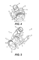
- FIG. 4 is a perspective view of a housing subassembly of the camera lens washing device illustrated in FIG. 1 ;
- FIG. 5 is an exploded perspective view of the housing subassembly illustrated in FIG. 4 ;
- FIG. 6 is a perspective view of a camera lens washing device according to an alternative exemplary embodiment of the present invention.
- FIG. 7 is an exploded perspective view of the camera lens washing device illustrated in FIG. 6 .
- the present invention relates to a washing device 100 and 100 ′ for a camera lens 10 , such as for a camera mounted on a vehicle.
- the camera lens washing device 100 and 100 ′ has a simplified design while providing improving washing and field of view of the lens.
- the camera lens washing device 100 and 100 ′ includes an outer housing 102 and an inner ring 104 that cooperate with one another to form multiple nozzles 106 therebetween that are preferably disposed around a top side of the camera lens 10 for discharging fluid, such as water or other lens washing fluid, radially inwardly and toward the camera lens 10 for cleaning the same.
- the washing fluid is preferably under pressure to be distributed through the nozzles 106 creating multiple fluid jets from different locations toward the center of the camera lens 10 .
- the camera lens washing device 100 and 100 ′ has an improved compact design and camera field of view.
- Outer housing 102 generally includes a main body 110 that may be substantially ring shaped and includes a main opening 112 therein for receiving the camera lens 10 .
- One end of main body 110 is an attachment end 114 configured to mount to a camera housing 12 of the lens 10 .
- the other end of main body 110 is an exposed end 116 , as best seen in FIG. 1 .
- attachment end 114 includes one or more latching arms 118 that extend from main body 110 in a direction away from exposed end 116 for snap fitting onto the camera housing 12 .
- attachment end 114 may include other known methods of attachment, such as screw fastening or adhesive.
- Main opening 112 of outer housing 102 includes a top side 120 and an opposite bottom side 122 .
- a fluid source attachment 124 is provided in the outer housing 102 that is configured for engagement with a fluid source, such as a water hose or line.
- Fluid source attachment 124 may be an extension with an inner bore 126 in fluid communication with the nozzles 106 .
- Fluid source attachment 124 is preferably located at the top side 120 of main opening 112 in outer housing 102 to allow the fluid to flow downwardly towards the nozzles 106 .
- Exposed end 116 of outer housing 102 includes an end face 130 .
- a recessed area 132 extends inwardly from end face 130 for accepting inner ring 104 .
- Extending inwardly from main opening 112 are spaced tabs 134 which define fluid path slots 136 therebetween, as best seen in FIGS. 4 and 5 , which are in fluid communication with fluid source attachment 124 .
- Spaces tabs 134 may be located adjacent to recessed area 132 .
- an alignment member 138 Remote from the spaced tabs 134 on main body 110 is an alignment member 138 for aligning inner ring 104 with respect to outer housing 102 .
- Inner ring 104 is configured and sized to frame the camera lens 10 , as best seen in FIG. 1 .
- Inner ring 104 is preferably formed separately from outer housing 102 and is received in recessed area 132 of outer housing 102 .
- Inner ring 104 may be fixed to outer housing 102 , such as by laser welding inner ring 104 in recessed area 132 or by other known attachments.
- Inner ring 104 includes a mounting face 140 ( FIG. 5 ) that engages recessed area 132 and an opposite exposed face ( FIG. 1 ) 142 .
- An inner diameter surface 144 of inner ring 104 is between mounting face 140 and exposed face 142 .
- exposed face 142 of inner ring 104 does not extend beyond and is substantially flush with end face 130 of outer housing 102 , as seen in FIG. 2 , thereby not negatively impacting the camera's field of view.
- a plurality of channels 150 are provided in inner diameter surface 144 of inner ring 104 , as best seen in FIGS. 4 and 5 .
- Channels 150 substantially align with fluid path slots 136 of outer housing 102 to form the nozzles 106 .
- Each channel 150 substantially aligns with one of the fluid path slots 136 to form one of the nozzles 106 .
- Each channel 150 preferably extends into mounting face 140 of inner ring 104 and may include a step 152 to facilitate fluid flow through nozzles 106 .
- alignment member 154 Remote from channels 150 is an alignment member 154 that corresponds to alignment member 138 of outer housing 102 to ensure proper alignment between inner ring 104 and outer housing 104 to form the nozzles 106 .
- alignment member 154 may be a protruding flange ( FIG. 5 ), for example, and alignment member 138 may be a cut-out in main body 110 sized to accept flange 154 , or vice versa.
- the alignment member 138 preferably includes a channel that allows the fluid or water from the fluid source attachment 126 to pass therethrough to the channels 150 and slots 136 of nozzles 106 .
- Nozzles 106 are preferably located at or near the top side 120 of main opening 112 such that fluid from fluid source attachment 124 can flow downwardly through slots 136 and channels 150 so that nozzles 106 discharge the fluid directly onto the camera lens 10 . And because nozzles 106 are on the top of the lens 10 , gravity will subsequently wash away the fluid from the lens 10 . In a preferred embodiment, none of the nozzles 106 are located at the bottom, that is the bottom side 122 of the main opening 112 such that the nozzles 106 are only provided near or at top side 120 . The nozzles 106 may be evenly spaced from one another and radially arranged with respect to the lens 10 , as best seen in FIG. 4 .
- a sealing member 160 ( FIG. 3 ), such as a seal ring, may be provided on attachment end 114 to seal the plurality of channels 150 and slots 136 between inner ring 104 and outer housing 102 .
- FIGS. 6 and 7 illustrate an alternative embodiment of the camera lens washing device 100 ′.
- Camera lens washing device 100 ′ is substantially the same as the camera lens washing device 100 of the first embodiment, except that the outer housing 102 ′ thereof includes shroud extension 200 for attaching to a camera module 14 that supports the camera lens 10 .
- Shroud extension 200 replaces latch arms 118 and may include an engagement member 202 , such as a plurality of teeth, for engaging the camera module 14 .
- Shroud extension 200 is extends away from the exposed end 116 of outer housing 102 ′ and is preferably sized to substantially surround the camera lens.
Abstract
Description
Claims (24)
Priority Applications (7)
| Application Number | Priority Date | Filing Date | Title |
|---|---|---|---|
| US15/267,938 US10268038B2 (en) | 2016-09-16 | 2016-09-16 | Camera lens washing device |
| US15/428,706 US10422992B2 (en) | 2016-09-16 | 2017-02-09 | Camera lens washing device |
| US15/491,551 US10391523B2 (en) | 2016-09-16 | 2017-04-19 | Sensor washing device |
| PCT/US2017/049383 WO2018052715A1 (en) | 2016-09-16 | 2017-09-14 | Camera lens/sensor washing device |
| DE112017004676.9T DE112017004676T5 (en) | 2016-09-16 | 2017-09-14 | Camera Lens / sensor cleaning device |
| US15/802,933 US10682988B2 (en) | 2016-09-16 | 2017-11-03 | Enhanced washing device for vehicle accessory |
| US16/744,782 US20200156596A1 (en) | 2016-09-16 | 2020-01-16 | Enhanced washing device for vehicle accessory |
Applications Claiming Priority (1)
| Application Number | Priority Date | Filing Date | Title |
|---|---|---|---|
| US15/267,938 US10268038B2 (en) | 2016-09-16 | 2016-09-16 | Camera lens washing device |
Related Child Applications (1)
| Application Number | Title | Priority Date | Filing Date |
|---|---|---|---|
| US15/428,706 Continuation-In-Part US10422992B2 (en) | 2016-09-16 | 2017-02-09 | Camera lens washing device |
Publications (2)
| Publication Number | Publication Date |
|---|---|
| US20180081169A1 US20180081169A1 (en) | 2018-03-22 |
| US10268038B2 true US10268038B2 (en) | 2019-04-23 |
Family
ID=61621020
Family Applications (1)
| Application Number | Title | Priority Date | Filing Date |
|---|---|---|---|
| US15/267,938 Expired - Fee Related US10268038B2 (en) | 2016-09-16 | 2016-09-16 | Camera lens washing device |
Country Status (1)
| Country | Link |
|---|---|
| US (1) | US10268038B2 (en) |
Cited By (1)
| Publication number | Priority date | Publication date | Assignee | Title |
|---|---|---|---|---|
| US10928225B1 (en) | 2019-09-19 | 2021-02-23 | Ford Global Technologies, Llc | Vehicle sensor assembly |
Families Citing this family (2)
| Publication number | Priority date | Publication date | Assignee | Title |
|---|---|---|---|---|
| US10232828B2 (en) * | 2016-11-17 | 2019-03-19 | GM Global Technology Operations LLC | Circular spray nozzle system and method for cleaning a cylindrical surface of a component |
| DE102017206265A1 (en) * | 2017-04-12 | 2018-10-18 | Continental Automotive Gmbh | Cleaning device for cleaning a transparent element of an optical or optoelectronic device |
Citations (52)
| Publication number | Priority date | Publication date | Assignee | Title |
|---|---|---|---|---|
| US5588055A (en) | 1995-01-27 | 1996-12-24 | Williamson; Robert | Telephone holder with mounting assembly |
| US5779205A (en) | 1996-12-23 | 1998-07-14 | Ching; Allen | Extensible windshield portable phone holder |
| US20040218042A1 (en) * | 2003-03-31 | 2004-11-04 | Mazda Motor Corporation | Monitoring system for vehicle |
| EP1648737A1 (en) | 2003-07-29 | 2006-04-26 | Valeo Systemes D'essuyage | Rear viewing device for an automobile |
| WO2008014870A1 (en) | 2006-08-02 | 2008-02-07 | A. Raymond Et Cie | Device for securing a camera to a carrier |
| WO2009056510A1 (en) | 2007-10-31 | 2009-05-07 | Huf Hülsbeck & Fürst Gmbh & Co. Kg | Device having a camera unit |
| US20090122141A1 (en) | 2007-11-09 | 2009-05-14 | Akihiro Nakamura | Camera mounting structure, camera mounting method and exterior panel component of a vehicle |
| US20090309971A1 (en) | 2006-08-22 | 2009-12-17 | Heiko Schuetz | Device for opening a vehicle lock and for capturing an image on the exterior of the vehicle |
| US20100040361A1 (en) | 2006-10-09 | 2010-02-18 | Huf Hulsbeck & Furst Gmbh & Co. Kg | Device for a motor vehicle, comprising a rotatably mounted camera unit |
| US20110155874A1 (en) | 2008-08-28 | 2011-06-30 | Leopold Kostal Gmbh & Co. Kg | Sensor arrangement for a vehicle window |
| US20110292212A1 (en) | 2010-05-27 | 2011-12-01 | Asmo Co., Ltd. | Washer nozzle for vehicle mounted camera, vehicle mounted camera, and washer device for vehicle |
| US20120007984A1 (en) | 2009-04-02 | 2012-01-12 | Huf Hulsbeck & Furst Gmbh & Co. Kg | Device having a camera unit for recording images of the outer area of a motor vehicle |
| US20120207461A1 (en) | 2011-02-10 | 2012-08-16 | Denso Corporation | In-vehicle camera |
| US20120315027A1 (en) | 2010-01-15 | 2012-12-13 | Huf Hülsbeck & Fürst Gmbh & Co. Kg | Device for a motor vehicle comprising a movably mounted camera unit and motor vehicle |
| DE102011078230A1 (en) | 2011-06-28 | 2013-01-03 | Kuhnke Automotive Gmbh & Co. Kg | Device for moving object, particularly camera or vehicle camera, at or in vehicle, particularly motor vehicle or automobiles, has drive, particularly electric drive motor for moving object, where object is pivoted around axis |
| US20130182112A1 (en) | 2010-09-13 | 2013-07-18 | Audi Ag | Camera arrangement for a vehicle and method for installing a camera arrangement in a vehicle |
| US20130294758A1 (en) | 2010-11-16 | 2013-11-07 | Huf Hulsbeck & Furst Gmbh & Co. | Device comprising a camera unit and a protection element which has a compact displacement path |
| US20130335624A1 (en) | 2011-02-11 | 2013-12-19 | Huf Hulsbeck & Furst Gmbh & Co. Kg | Component Assembly for Simplified Installation on a Vehicle |
| US8671504B2 (en) | 2010-04-28 | 2014-03-18 | Denso Corporation | Cover of vehicle optical sensor and vehicle optical sensor device |
| US20140085467A1 (en) | 2011-02-11 | 2014-03-27 | Huf Hülsbeck & Fürst Gmbh & Co. Kg | Camera arrangement for a vehicle and an installation method |
| US20140169866A1 (en) | 2011-07-26 | 2014-06-19 | Daimler Ag | Fastening Arrangement of a Sensor Element on a Fastening Element of a Motor Vehicle |
| US8857687B1 (en) | 2011-08-11 | 2014-10-14 | Byungseol An | Car mount for an electronic device |
| US20150008300A1 (en) | 2012-02-02 | 2015-01-08 | Illinois Tool Works Inc. | Vehicle camera-securing assembly |
| US20150030319A1 (en) | 2013-07-23 | 2015-01-29 | Honda Motor Co., Ltd. | Camera unit |
| WO2015011439A1 (en) | 2013-07-22 | 2015-01-29 | Morgan Advanced Materials Plc. | Inorganic fibre compositions |
| US20150042804A1 (en) | 2012-03-28 | 2015-02-12 | Denso Corporation | In-vehicle camera |
| US20150097013A1 (en) | 2013-10-04 | 2015-04-09 | Magna Mirrors Of America, Inc. | Accessory system for a vehicle |
| US20150109447A1 (en) | 2012-03-19 | 2015-04-23 | Denso Corporation | In-vehicle camera |
| US20150185592A1 (en) * | 2012-07-02 | 2015-07-02 | Agricam Ab | Camera housings, camera modules, and monitoring systems |
| CN104768802A (en) | 2012-10-10 | 2015-07-08 | 霍弗·霍斯贝克及弗斯特两合公司 | Device for holding a camera having four joints |
| US20150203077A1 (en) | 2012-07-11 | 2015-07-23 | Nissan Motor Co., Ltd. | Cleaning device for vehicle-mounted camera and method of cleaning vehicle-mounted camera |
| WO2015110439A1 (en) | 2014-01-24 | 2015-07-30 | Bayerische Motoren Werke Aktiengesellschaft | Device for cleaning an optical lens of a parking assistance camera |
| US20150258944A1 (en) | 2012-10-10 | 2015-09-17 | Huf Hülsbeck & Fürst Gmbh & Co. Kg | Device for holding a camera having four joints |
| US20150274089A1 (en) | 2012-10-10 | 2015-10-01 | Huf Hülsbeck & Fürst Gmbh & Co. Kg | Device for holding a camera having a linear guide |
| US9150165B1 (en) | 2014-11-21 | 2015-10-06 | Nissan North America, Inc. | Vehicle camera assembly |
| US20150344001A1 (en) | 2014-05-27 | 2015-12-03 | Fico Transpar, S.A. | Cleaning device and system for vehicle-mounted optic surface and vehicle-mounted optic sensor with cleaning device |
| US20150343999A1 (en) | 2014-05-27 | 2015-12-03 | Fico Transpar, S.A. | System and method for cleaning a vehicle-mounted optic lens |
| US20160001330A1 (en) | 2011-03-10 | 2016-01-07 | Alan Romack | Integrated automotive system, nozzle assembly and remote control method for cleaning an image sensor's exterior or objective lens surface |
| US20160103316A1 (en) | 2014-10-10 | 2016-04-14 | Valeo Systèmes d'Essuyage | Device for cleaning a motor vehicle driving aid camera |
| US20160101735A1 (en) | 2014-10-10 | 2016-04-14 | Valeo Systèmes d'Essuyage | Device for cleaning a motor vehicle driving aid camera |
| WO2016083317A1 (en) | 2014-11-24 | 2016-06-02 | Kautex Textron Gmbh & Co. Kg | Integrated on-board vehicle vision and cleaning system |
| US9380190B2 (en) | 2012-08-06 | 2016-06-28 | Gentex Corporation | Rotating lens apparatus |
| US20160245011A1 (en) | 2015-02-19 | 2016-08-25 | Huf Huelsbeck & Fuerst Gmbh & Co. Kg | Assembly for a vehicle |
| US20160272163A1 (en) * | 2015-03-17 | 2016-09-22 | Magna Electronics Inc. | Vehicle camera with lens washer system |
| WO2016177577A1 (en) | 2015-05-06 | 2016-11-10 | Huf Hülsbeck & Fürst Gmbh & Co. Kg | Device for capturing images of an outer area of a motor vehicle |
| US20160347258A1 (en) | 2014-02-11 | 2016-12-01 | Huf Hülsbeck & Fürst Gmbh & Co. Kg | Camera Device |
| EP3103684A1 (en) | 2015-06-11 | 2016-12-14 | Continental Automotive GmbH | Camera bracket for a vehicle |
| US20170050581A1 (en) | 2014-02-11 | 2017-02-23 | Huf Hulsbeck & Furst Gmbh & Co. Kg | Compact camera device |
| US20170064161A1 (en) | 2014-02-11 | 2017-03-02 | Huf Hülsbeck & GmbH & Co. KG | Camera device with additional function |
| US20170106808A1 (en) | 2015-10-14 | 2017-04-20 | GM Global Technology Operations LLC | Vehicle with camera unit |
| US9910272B2 (en) | 2014-06-10 | 2018-03-06 | Ford Global Technologies, Llc | Integrated camera mounting and image window cleaning device |
| US20180201232A1 (en) * | 2015-09-14 | 2018-07-19 | Conti Temic Microelectronic Gmbh | Cleaning Device for Cleaning a Transparent Camera Cover |
-
2016
- 2016-09-16 US US15/267,938 patent/US10268038B2/en not_active Expired - Fee Related
Patent Citations (67)
| Publication number | Priority date | Publication date | Assignee | Title |
|---|---|---|---|---|
| US5588055A (en) | 1995-01-27 | 1996-12-24 | Williamson; Robert | Telephone holder with mounting assembly |
| US5779205A (en) | 1996-12-23 | 1998-07-14 | Ching; Allen | Extensible windshield portable phone holder |
| US20040218042A1 (en) * | 2003-03-31 | 2004-11-04 | Mazda Motor Corporation | Monitoring system for vehicle |
| EP1648737A1 (en) | 2003-07-29 | 2006-04-26 | Valeo Systemes D'essuyage | Rear viewing device for an automobile |
| WO2008014870A1 (en) | 2006-08-02 | 2008-02-07 | A. Raymond Et Cie | Device for securing a camera to a carrier |
| US8243137B2 (en) | 2006-08-22 | 2012-08-14 | Huf Hulsbeck & Furst Gmbh & Co. Kg | Device for opening a vehicle lock and for capturing an image on the exterior of the vehicle |
| US20090309971A1 (en) | 2006-08-22 | 2009-12-17 | Heiko Schuetz | Device for opening a vehicle lock and for capturing an image on the exterior of the vehicle |
| US20100040361A1 (en) | 2006-10-09 | 2010-02-18 | Huf Hulsbeck & Furst Gmbh & Co. Kg | Device for a motor vehicle, comprising a rotatably mounted camera unit |
| US7891886B2 (en) | 2006-10-09 | 2011-02-22 | Huf Hulsbeck & Furst Gmbh & Co. Kg | Device for a motor vehicle, comprising a rotatably mounted camera unit |
| WO2009056510A1 (en) | 2007-10-31 | 2009-05-07 | Huf Hülsbeck & Fürst Gmbh & Co. Kg | Device having a camera unit |
| US20090122141A1 (en) | 2007-11-09 | 2009-05-14 | Akihiro Nakamura | Camera mounting structure, camera mounting method and exterior panel component of a vehicle |
| US8444329B2 (en) | 2007-11-09 | 2013-05-21 | Sony Corporation | Camera mounting structure, camera mounting method and exterior panel component of a vehicle |
| US20110155874A1 (en) | 2008-08-28 | 2011-06-30 | Leopold Kostal Gmbh & Co. Kg | Sensor arrangement for a vehicle window |
| US8448914B2 (en) | 2008-08-28 | 2013-05-28 | Leopold Kostal Gmbh & Co. Kg | Sensor arrangement for a vehicle window |
| US20120007984A1 (en) | 2009-04-02 | 2012-01-12 | Huf Hulsbeck & Furst Gmbh & Co. Kg | Device having a camera unit for recording images of the outer area of a motor vehicle |
| US8988526B2 (en) | 2009-04-02 | 2015-03-24 | Huf Hulsbeck & Furst Gmbh & Co. Kg | Device having a camera unit for recording images of the outer area of a motor vehicle |
| US20120315027A1 (en) | 2010-01-15 | 2012-12-13 | Huf Hülsbeck & Fürst Gmbh & Co. Kg | Device for a motor vehicle comprising a movably mounted camera unit and motor vehicle |
| US8821043B2 (en) | 2010-01-15 | 2014-09-02 | Huf Hulsbeck & Furst Gmbh & Co. Kg | Device for a motor vehicle comprising a movably mounted camera unit and motor vehicle |
| US8671504B2 (en) | 2010-04-28 | 2014-03-18 | Denso Corporation | Cover of vehicle optical sensor and vehicle optical sensor device |
| US20110292212A1 (en) | 2010-05-27 | 2011-12-01 | Asmo Co., Ltd. | Washer nozzle for vehicle mounted camera, vehicle mounted camera, and washer device for vehicle |
| US20130182112A1 (en) | 2010-09-13 | 2013-07-18 | Audi Ag | Camera arrangement for a vehicle and method for installing a camera arrangement in a vehicle |
| US8836789B2 (en) | 2010-09-13 | 2014-09-16 | Audi Ag | Camera arrangement for a vehicle and method for installing a camera arrangement in a vehicle |
| US8961044B2 (en) | 2010-11-16 | 2015-02-24 | Huf Hulsbeck & Furst Gmbh & Co. Kg | Device comprising a camera unit and a protection element which has a compact displacement path |
| US20130294758A1 (en) | 2010-11-16 | 2013-11-07 | Huf Hulsbeck & Furst Gmbh & Co. | Device comprising a camera unit and a protection element which has a compact displacement path |
| US20120207461A1 (en) | 2011-02-10 | 2012-08-16 | Denso Corporation | In-vehicle camera |
| US9193308B2 (en) | 2011-02-10 | 2015-11-24 | Denso Corporation | In-vehicle camera |
| US9380192B2 (en) | 2011-02-11 | 2016-06-28 | Huf Hulsbeck & Furst Gmbh & Co. Kg | Component assembly for simplified installation on a vehicle |
| US20130335624A1 (en) | 2011-02-11 | 2013-12-19 | Huf Hulsbeck & Furst Gmbh & Co. Kg | Component Assembly for Simplified Installation on a Vehicle |
| US20140085467A1 (en) | 2011-02-11 | 2014-03-27 | Huf Hülsbeck & Fürst Gmbh & Co. Kg | Camera arrangement for a vehicle and an installation method |
| US20160001330A1 (en) | 2011-03-10 | 2016-01-07 | Alan Romack | Integrated automotive system, nozzle assembly and remote control method for cleaning an image sensor's exterior or objective lens surface |
| DE102011078230A1 (en) | 2011-06-28 | 2013-01-03 | Kuhnke Automotive Gmbh & Co. Kg | Device for moving object, particularly camera or vehicle camera, at or in vehicle, particularly motor vehicle or automobiles, has drive, particularly electric drive motor for moving object, where object is pivoted around axis |
| US20140169866A1 (en) | 2011-07-26 | 2014-06-19 | Daimler Ag | Fastening Arrangement of a Sensor Element on a Fastening Element of a Motor Vehicle |
| US9580023B2 (en) | 2011-07-26 | 2017-02-28 | Daimler Ag | Fastening arrangement of a camera on a fastening element of a motor vehicle |
| US8857687B1 (en) | 2011-08-11 | 2014-10-14 | Byungseol An | Car mount for an electronic device |
| US20150008300A1 (en) | 2012-02-02 | 2015-01-08 | Illinois Tool Works Inc. | Vehicle camera-securing assembly |
| US9446721B2 (en) | 2012-02-02 | 2016-09-20 | Illinois Tool Works Inc. | Vehicle camera-securing assembly |
| US20150109447A1 (en) | 2012-03-19 | 2015-04-23 | Denso Corporation | In-vehicle camera |
| US20150042804A1 (en) | 2012-03-28 | 2015-02-12 | Denso Corporation | In-vehicle camera |
| US20150185592A1 (en) * | 2012-07-02 | 2015-07-02 | Agricam Ab | Camera housings, camera modules, and monitoring systems |
| US20150203077A1 (en) | 2012-07-11 | 2015-07-23 | Nissan Motor Co., Ltd. | Cleaning device for vehicle-mounted camera and method of cleaning vehicle-mounted camera |
| US9380190B2 (en) | 2012-08-06 | 2016-06-28 | Gentex Corporation | Rotating lens apparatus |
| US20150274089A1 (en) | 2012-10-10 | 2015-10-01 | Huf Hülsbeck & Fürst Gmbh & Co. Kg | Device for holding a camera having a linear guide |
| US20150258944A1 (en) | 2012-10-10 | 2015-09-17 | Huf Hülsbeck & Fürst Gmbh & Co. Kg | Device for holding a camera having four joints |
| CN104768802A (en) | 2012-10-10 | 2015-07-08 | 霍弗·霍斯贝克及弗斯特两合公司 | Device for holding a camera having four joints |
| US9457733B2 (en) | 2012-10-10 | 2016-10-04 | Huf Hülsbeck & Fürst Gmbh & Co. Kg | Device for holding a camera having a linear guide |
| US9725049B2 (en) | 2012-10-10 | 2017-08-08 | Huf Hülsbeck & Fürst Gmbh & Co. Kg | Device for holding a camera having four joints |
| WO2015011439A1 (en) | 2013-07-22 | 2015-01-29 | Morgan Advanced Materials Plc. | Inorganic fibre compositions |
| US20150030319A1 (en) | 2013-07-23 | 2015-01-29 | Honda Motor Co., Ltd. | Camera unit |
| US9487161B2 (en) | 2013-10-04 | 2016-11-08 | Magna Mirrors Of America, Inc. | Accessory system for a vehicle |
| US20150097013A1 (en) | 2013-10-04 | 2015-04-09 | Magna Mirrors Of America, Inc. | Accessory system for a vehicle |
| WO2015110439A1 (en) | 2014-01-24 | 2015-07-30 | Bayerische Motoren Werke Aktiengesellschaft | Device for cleaning an optical lens of a parking assistance camera |
| US20160347258A1 (en) | 2014-02-11 | 2016-12-01 | Huf Hülsbeck & Fürst Gmbh & Co. Kg | Camera Device |
| US20170064161A1 (en) | 2014-02-11 | 2017-03-02 | Huf Hülsbeck & GmbH & Co. KG | Camera device with additional function |
| US20170050581A1 (en) | 2014-02-11 | 2017-02-23 | Huf Hulsbeck & Furst Gmbh & Co. Kg | Compact camera device |
| US20150343999A1 (en) | 2014-05-27 | 2015-12-03 | Fico Transpar, S.A. | System and method for cleaning a vehicle-mounted optic lens |
| US20150344001A1 (en) | 2014-05-27 | 2015-12-03 | Fico Transpar, S.A. | Cleaning device and system for vehicle-mounted optic surface and vehicle-mounted optic sensor with cleaning device |
| US9910272B2 (en) | 2014-06-10 | 2018-03-06 | Ford Global Technologies, Llc | Integrated camera mounting and image window cleaning device |
| US20160103316A1 (en) | 2014-10-10 | 2016-04-14 | Valeo Systèmes d'Essuyage | Device for cleaning a motor vehicle driving aid camera |
| US20160101735A1 (en) | 2014-10-10 | 2016-04-14 | Valeo Systèmes d'Essuyage | Device for cleaning a motor vehicle driving aid camera |
| US9150165B1 (en) | 2014-11-21 | 2015-10-06 | Nissan North America, Inc. | Vehicle camera assembly |
| WO2016083317A1 (en) | 2014-11-24 | 2016-06-02 | Kautex Textron Gmbh & Co. Kg | Integrated on-board vehicle vision and cleaning system |
| US20160245011A1 (en) | 2015-02-19 | 2016-08-25 | Huf Huelsbeck & Fuerst Gmbh & Co. Kg | Assembly for a vehicle |
| US20160272163A1 (en) * | 2015-03-17 | 2016-09-22 | Magna Electronics Inc. | Vehicle camera with lens washer system |
| WO2016177577A1 (en) | 2015-05-06 | 2016-11-10 | Huf Hülsbeck & Fürst Gmbh & Co. Kg | Device for capturing images of an outer area of a motor vehicle |
| EP3103684A1 (en) | 2015-06-11 | 2016-12-14 | Continental Automotive GmbH | Camera bracket for a vehicle |
| US20180201232A1 (en) * | 2015-09-14 | 2018-07-19 | Conti Temic Microelectronic Gmbh | Cleaning Device for Cleaning a Transparent Camera Cover |
| US20170106808A1 (en) | 2015-10-14 | 2017-04-20 | GM Global Technology Operations LLC | Vehicle with camera unit |
Cited By (1)
| Publication number | Priority date | Publication date | Assignee | Title |
|---|---|---|---|---|
| US10928225B1 (en) | 2019-09-19 | 2021-02-23 | Ford Global Technologies, Llc | Vehicle sensor assembly |
Also Published As
| Publication number | Publication date |
|---|---|
| US20180081169A1 (en) | 2018-03-22 |
Similar Documents
| Publication | Publication Date | Title |
|---|---|---|
| US10391523B2 (en) | Sensor washing device | |
| US10268038B2 (en) | Camera lens washing device | |
| US10821941B2 (en) | Foreign material adhesion preventing device and camera device provided with same | |
| CN105128826B (en) | The cleaning device and system of vehicle-mounted optical surface and vehicle-mounted optical sensor with cleaning device | |
| CN108025704B (en) | Cleaning device for cleaning transparent cover of camera | |
| US8792003B2 (en) | Camera device | |
| EP3131785B1 (en) | Integrated multi image sensor and lens washing nozzle assembly and method for simultaneously cleaning multiple image sensors | |
| EP3489098B1 (en) | Integrated automotive system, compact, low-profile nozzle assembly and compact fluidic circuit for cleaning a wide-angle image sensor's exterior surface | |
| US10422992B2 (en) | Camera lens washing device | |
| US20110292212A1 (en) | Washer nozzle for vehicle mounted camera, vehicle mounted camera, and washer device for vehicle | |
| US20090052722A1 (en) | Speaker system and fitting device | |
| CN109312765B (en) | Flow control system, jumper hose element and fluid flow management method | |
| US20180319350A1 (en) | Automobile Accessory Mounting Support | |
| EP3279914B1 (en) | Multi-optical axis photoelectric sensor | |
| US9988020B2 (en) | Washer nozzle for a screen wash system | |
| CN109917606B (en) | Camera assembly and vehicle | |
| CN112660072B (en) | Laser radar base, laser radar device and automatic driving vehicle | |
| CN209746335U (en) | camera subassembly and vehicle | |
| EP3480069B1 (en) | Enhanced washing device for vehicle accessory | |
| US20180267297A1 (en) | Camera module for a motor vehicle | |
| CN209387984U (en) | A kind of lens module | |
| CN214235210U (en) | Cleaning device and camera | |
| CN110858020A (en) | Detachable lens, assembling method thereof and optical imaging device | |
| CN114289411B (en) | Camera assembly | |
| CN210139853U (en) | Cleaning device and automobile |
Legal Events
| Date | Code | Title | Description |
|---|---|---|---|
| AS | Assignment |
Owner name: METHODE ELECTRONICS, INC., ILLINOIS Free format text: ASSIGNMENT OF ASSIGNORS INTEREST;ASSIGNOR:KARASIK, VLADIMIR;REEL/FRAME:039975/0530 Effective date: 20160920 |
|
| STPP | Information on status: patent application and granting procedure in general |
Free format text: PUBLICATIONS -- ISSUE FEE PAYMENT VERIFIED |
|
| STCF | Information on status: patent grant |
Free format text: PATENTED CASE |
|
| FEPP | Fee payment procedure |
Free format text: MAINTENANCE FEE REMINDER MAILED (ORIGINAL EVENT CODE: REM.); ENTITY STATUS OF PATENT OWNER: LARGE ENTITY |
|
| LAPS | Lapse for failure to pay maintenance fees |
Free format text: PATENT EXPIRED FOR FAILURE TO PAY MAINTENANCE FEES (ORIGINAL EVENT CODE: EXP.); ENTITY STATUS OF PATENT OWNER: LARGE ENTITY |
|
| STCH | Information on status: patent discontinuation |
Free format text: PATENT EXPIRED DUE TO NONPAYMENT OF MAINTENANCE FEES UNDER 37 CFR 1.362 |
|
| FP | Lapsed due to failure to pay maintenance fee |
Effective date: 20230423 |