EP2734371B3 - Druckkopf für einen tintenstrahldrucker - Google Patents
Druckkopf für einen tintenstrahldrucker Download PDFInfo
- Publication number
- EP2734371B3 EP2734371B3 EP12735287.0A EP12735287A EP2734371B3 EP 2734371 B3 EP2734371 B3 EP 2734371B3 EP 12735287 A EP12735287 A EP 12735287A EP 2734371 B3 EP2734371 B3 EP 2734371B3
- Authority
- EP
- European Patent Office
- Prior art keywords
- nozzle
- ink
- ram
- supply channel
- print head
- Prior art date
- Legal status (The legal status is an assumption and is not a legal conclusion. Google has not performed a legal analysis and makes no representation as to the accuracy of the status listed.)
- Active
Links
Images

Classifications
-
- B—PERFORMING OPERATIONS; TRANSPORTING
- B41—PRINTING; LINING MACHINES; TYPEWRITERS; STAMPS
- B41J—TYPEWRITERS; SELECTIVE PRINTING MECHANISMS, i.e. MECHANISMS PRINTING OTHERWISE THAN FROM A FORME; CORRECTION OF TYPOGRAPHICAL ERRORS
- B41J2/00—Typewriters or selective printing mechanisms characterised by the printing or marking process for which they are designed
- B41J2/005—Typewriters or selective printing mechanisms characterised by the printing or marking process for which they are designed characterised by bringing liquid or particles selectively into contact with a printing material
- B41J2/01—Ink jet
- B41J2/17—Ink jet characterised by ink handling
- B41J2/175—Ink supply systems ; Circuit parts therefor
-
- B—PERFORMING OPERATIONS; TRANSPORTING
- B41—PRINTING; LINING MACHINES; TYPEWRITERS; STAMPS
- B41J—TYPEWRITERS; SELECTIVE PRINTING MECHANISMS, i.e. MECHANISMS PRINTING OTHERWISE THAN FROM A FORME; CORRECTION OF TYPOGRAPHICAL ERRORS
- B41J2/00—Typewriters or selective printing mechanisms characterised by the printing or marking process for which they are designed
- B41J2/005—Typewriters or selective printing mechanisms characterised by the printing or marking process for which they are designed characterised by bringing liquid or particles selectively into contact with a printing material
- B41J2/01—Ink jet
- B41J2/015—Ink jet characterised by the jet generation process
- B41J2/04—Ink jet characterised by the jet generation process generating single droplets or particles on demand
- B41J2/045—Ink jet characterised by the jet generation process generating single droplets or particles on demand by pressure, e.g. electromechanical transducers
-
- B—PERFORMING OPERATIONS; TRANSPORTING
- B41—PRINTING; LINING MACHINES; TYPEWRITERS; STAMPS
- B41J—TYPEWRITERS; SELECTIVE PRINTING MECHANISMS, i.e. MECHANISMS PRINTING OTHERWISE THAN FROM A FORME; CORRECTION OF TYPOGRAPHICAL ERRORS
- B41J2/00—Typewriters or selective printing mechanisms characterised by the printing or marking process for which they are designed
- B41J2/005—Typewriters or selective printing mechanisms characterised by the printing or marking process for which they are designed characterised by bringing liquid or particles selectively into contact with a printing material
- B41J2/01—Ink jet
- B41J2/135—Nozzles
- B41J2/14—Structure thereof only for on-demand ink jet heads
-
- B—PERFORMING OPERATIONS; TRANSPORTING
- B41—PRINTING; LINING MACHINES; TYPEWRITERS; STAMPS
- B41J—TYPEWRITERS; SELECTIVE PRINTING MECHANISMS, i.e. MECHANISMS PRINTING OTHERWISE THAN FROM A FORME; CORRECTION OF TYPOGRAPHICAL ERRORS
- B41J2/00—Typewriters or selective printing mechanisms characterised by the printing or marking process for which they are designed
- B41J2/005—Typewriters or selective printing mechanisms characterised by the printing or marking process for which they are designed characterised by bringing liquid or particles selectively into contact with a printing material
- B41J2/01—Ink jet
- B41J2/015—Ink jet characterised by the jet generation process
- B41J2/04—Ink jet characterised by the jet generation process generating single droplets or particles on demand
- B41J2002/041—Electromagnetic transducer
-
- B—PERFORMING OPERATIONS; TRANSPORTING
- B41—PRINTING; LINING MACHINES; TYPEWRITERS; STAMPS
- B41J—TYPEWRITERS; SELECTIVE PRINTING MECHANISMS, i.e. MECHANISMS PRINTING OTHERWISE THAN FROM A FORME; CORRECTION OF TYPOGRAPHICAL ERRORS
- B41J2202/00—Embodiments of or processes related to ink-jet or thermal heads
- B41J2202/01—Embodiments of or processes related to ink-jet heads
- B41J2202/05—Heads having a valve
Definitions
- a print head for an inkjet printer comprises an ink supply channel and at least one nozzle, with the nozzle being assigned a movable tappet for effecting ink ejection from the ink supply channel.
- the term “rest position” should be understood to mean that a sealing body assumes a position in the ink supply channel of a print head that depends on the printing process, which means that no ink escapes from the Print head exits accordingly the printing of a substrate does not take place.
- the term “working position” is to be understood in the context in such a way that a closure body assumes a position in the ink supply channel that is dependent on the printing process and enables a substrate to be printed with ink.
- the term “means” is to be understood in the context such that contextually both the singular and the plural of the term can be meant.
- the term “pigments” is understood to mean particles in the ink with solid properties that are not soluble.
- the term “ink channel” is to be understood as synonymous with the term “ink supply channel” in the context.
- Inkjet printing is a widely used printing technique for printing on substrates.
- the printheads of inkjet printing devices generally include at least one ink supply channel and at least one nozzle for ejecting the ink from the ink supply channel.
- At least one piezo element is deformed by applying an electrical voltage to such an extent that the deformation generates a pressure wave in the ink chamber or the ink channel, which causes an ink droplet to be ejected through the nozzle.
- a print head of the type mentioned is, for example, from WO2008/044069 A known.
- nozzles which are in the form of narrow strips with a passage hole for ink, are moved or vibrated in order to cause droplets to be ejected from the nozzle.
- Conventional print heads which contain an ink supply channel and at least one nozzle, with each nozzle being assigned a closure body, include means which open a nozzle during the printing process. In the rest position, the nozzle is sealed by the closure body, so that the excess pressure ink is prevented from escaping from the ink supply channel. In an operative position, the plunger is lifted from the nozzle so that ink can flow into the nozzle and be ejected from the ink supply channel.
- Such a printhead is in the reference EP0445137B1 disclosed.
- the publication describes a print head for an inkjet printer with an ink chamber connected to an ink pressure source, in which several closure bodies are arranged, each closing a nozzle, which are each connected to a pull rod and the closure bodies are moved up and down in the ink chamber with a drive device.
- the closure body In the rest position, the closure body completely closes the ink spray nozzle. If the closure body is moved from the rest position to a working position, it is lifted or pulled back by the nozzle.
- the ink in the ink chamber is permanently pressurized so that the ink can only be ejected from the ink supply channel through the nozzle when the closure body is pulled back. As soon as the closure body has resumed its resting position, the ink injection nozzle is closed.
- FIG. 1 Another printhead is in the reference EP0787587B1 disclosed.
- the publication describes a closure body consisting of a piston with a axially associated locking pin is T-shaped.
- the closure body is located within a cylindrical chamber, with the outer diameter of the cylindrical piston approximately corresponding to the inner diameter of the chamber, so that the piston is moved up and down along the chamber wall in a sealing manner.
- the piston separates the chamber into two sections, with one section at the bottom having a faceplate containing a bored nozzle for ejecting ink drops. This area contains the ink and forms the ink chamber, which is connected to an ink pressure source.
- In the other chamber is a spring that presses against the breech body.
- the locking pin reaches into the drilled hole of the nozzle in the rest position and closes it, with a film of ink between the front plate and the piston. If an overpressure builds up in the ink chamber, the pressure causes the piston and thus the locking pin to be pulled back from the borehole from the rest position to a working position against the restoring force of a spring, whereupon the ink, which has been subjected to overpressure, flows into the borehole and out of the nozzle can be ejected. If the excess pressure is released, the locking pin is returned to the rest position and moves back into the drill hole, displacing the residual ink in the nozzle and closing the drill hole.
- the conventional print heads for carrying out printing processes with a closure body are designed for carrying out printing processes with relatively low printing frequencies, which is reflected in the relatively slow printing processes.
- the closure body When a printing step is carried out, the closure body is brought from the rest position into a working position, with the ink, which is subjected to excess pressure, exiting the ink channel through the nozzle. The flow of ink is stopped by the closure body hitting the nozzle, hitting the nozzle or the inner wall of the ink chamber and sealingly closing the inflow opening of the nozzle.
- the closure body In order to be able to cleanly separate an ink drop from the residual ink, the closure body must completely or sealingly close the inflow opening of the nozzle, with a collision of the closure body with the nozzle and/or the inner wall of the ink chamber being unavoidable. If the inflow opening of the nozzle is not completely closed with the closure body in a rest position, ink can emerge continuously from the ink channel through the nozzle in the form of an ink jet.
- the closure pin of the closure body reaches into the channel of the nozzle and closes it in the rest position, whereby the ink or ink film that can no longer be displaced in the ink chamber is due to the design and process in a section opposite the end face of the breech body piston cannot escape radially outward beyond the outer edge of the breech body piston, since the breech body piston is moved up and down sealingly on the chamber wall, so that the breech body still cannot collide with the ink film takes place. Collision with the ink film is somewhat softer than collision with a solid because, as is well known, a liquid has greater compressibility than a solid, so the lifespan can be increased at least partially.
- the document WO 98/56585 A1 describes a nozzle arrangement for an inkjet printer.
- individual ink droplets are ejected through an outlet opening of the nozzle in the direction of a print medium, in which a piston, which can move in an ink supply channel in the axial direction, is pushed with its end face against the inflow opening of the nozzle.
- a small amount of the ink in the ink supply channel is pressed into the outlet opening of the nozzle and is accelerated to such an extent that an ink drop is finally ejected.
- the piston is pretensioned by a spiral spring in the direction of the inflow opening of the nozzle, so that the face of the piston at the inflow opening of the nozzle - sealing it tightly - is brought to the plant.
- the piston To actuate the piston, it is lifted electromagnetically so that its face is lifted from the inflow opening of the nozzle and the ink can flow from the ink supply channel into the nozzle. If the magnetic field is then switched off again, the piston is again accelerated in the direction of the nozzle under the action of the restoring spring, and thus another drop of ink is ejected.
- This object is achieved according to the invention with a printing device of the type mentioned at the beginning in that the first means limit the movement of a ram end face to a movement between the reversal points and second means are provided for subjecting the ink in the ink supply channel to a negative pressure relative to the ambient air pressure.
- the ink supply channel is subjected to a negative pressure relative to the ambient pressure, at least in the area of the inflow opening of the nozzle.
- the negative pressure prevents ink from accidentally leaking from the ink channel.
- a closure body can be dispensed with.
- a plunger provided in the ink channel is used to eject the ink, the end of which is moved towards the nozzle channel, as a result of which ink is pressed through the nozzle channel and out of it, with a plunger/nozzle distance preferably being maintained throughout the printing process, i.e.
- the end face of the ram has a distance from the inflow opening of greater than zero at a reversal point and the inflow opening of the nozzle remains permanently open throughout the printing process.
- the ram according to the invention therefore does not assume the function of a closure body.
- the plunger does not have to function as a sealing body and the ink and/or pigments pushing between the end face of the plunger and the inlet opening of the nozzle channel do not interfere.
- Said inks can be used with the inventive printhead for texture printing.
- structure printing is understood to mean the application of three-dimensional shapes, lines, structures, etc. to at least one surface with smooth and/or rough areas, e.g. a wooden structure on an MDF/HDF board or tiles, Braille writing, or simulation of embossed writing, etc .
- the nozzle is preferably arranged stationarily on a side wall of the ink supply channel and a plunger is provided which is moved back and forth in the ink supply channel between two reversal points opposite the nozzle.
- the functional and characteristic structure and printing method of the printing device according to the invention is characterized in particular by the fact that means, preferably external means, are provided that generate a negative pressure in the ink supply channel, so that a nozzle can remain open throughout the printing process without ink escaping unintentionally .
- a ram is moved back and forth between two reversal points (U1) and (U2) opposite the nozzle, with the ram/nozzle distance being greater than zero, so that at no time during the printing process, i.e. before and /or periodically occurring collisions of the plunger with the nozzle occur during and/or after the ejection of ink.
- the plunger is not arranged in a sealing manner in the ink supply channel on an ink channel wall, i.e. it never forms a sealing body, with one end face of the plunger being moved from a starting point towards the inflow opening to eject the ink.
- One end of the plunger is only moved towards the inflow opening as far as a first reversal point (U1), this first reversal point (U1) being spaced apart from the inflow opening, so that the ink supply channel is not blocked even at the first reversal point (U1).
- the ink is pressed, starting from a stagnation area between the end face of the plunger and the area of the side wall with nozzle opposite the end face of the plunger, in the direction of the inflow opening of the nozzle, with ink inside of the ink supply channel to the outside, i.e. can flow beyond the outer edge of the plunger.
- ram face and “face” are to be understood as synonymous in the context.
- the face side of the ram does not necessarily mean a continuous area, but two or more areas can also be meant.
- the inventive printing method has shown that the service life of the print head is increased because the plunger avoids collisions with the liquid or liquid film located under the face of the plunger and/or the nozzle and/or the inner wall of the ink supply channel.
- the inventive print head for an inkjet printer comprises at least one ink supply channel and at least one nozzle with nozzle channel and inflow opening, it being possible for ink to be pressed out of the ink supply channel into the nozzle channel and ejected from it through the inflow opening, with the nozzle being arranged stationary on a side wall of the ink supply channel and the at least one nozzle is assigned a tappet with a tappet end face that is in the ink supply channel and is spaced opposite the inflow opening, the print head comprising first means for moving a tappet end face in the ink supply channel between a reversal point (U1) at a minimum distance from the inflow opening of the nozzle and one of the inflow opening of the nozzle at a maximum distance from the reversal point (U2), the first means limiting the movement of a tappet face to a movement between the reversal points (U1,U2) and second means being provided for subjecting the ink in the ink supply channel to a negative pressure relative to the ambient air
- the means for moving a ram include at least one actuator, wherein the at least one actuator can move the ram between two reversal points.
- the means for moving a ram can include at least one actuator and at least one spring.
- other conventional means of moving the ram may also be used.
- the preferred external means for subjecting the ink in the ink supply channel to a negative pressure relative to the ambient air pressure can be, for example, conventional vacuum pumps, with which it is possible to generate a corresponding counter-pressure to the ambient air pressure and the geodetic pressure of the ink in the nozzle channel in order to prevent the ink from leaking out of the to stop the ink supply channel.
- the ink pressure must be set in combination with the capillary pressure in such a way that no air is sucked in through the nozzle channel into the ink supply channel and that no ink escapes from the nozzle channel unintentionally.
- the ink pressure is the sum of the circulatory pressure and the meniscus negative pressure.
- the external means can be conventional pumps such as a circulation pump or a circulation pump. With the means, the ink is pumped through the ink supply channel, preferably permanently.
- the distance between a ram end face and the inflow opening is greater than zero at the minimally spaced reversal point (U1).
- each nozzle can be assigned a tappet.
- no side wall is made in one piece together with the nozzle and an end face of the at least one nozzle surrounding the inflow opening is formed flush with an inner surface of a side wall of the ink supply channel that is in contact with the ink .
- the above-mentioned object can also be achieved according to the invention with a method of the type mentioned at the outset in that the ink is subjected to a negative pressure relative to the ambient air pressure, at least during the time intervals in which printing is not to be carried out, at least in the area of the inflow opening of the nozzle, as a result an outflow of the ink from the nozzle channel is prevented even without a sealing body and that, in order to eject the ink, an end face of the plunger is moved from a starting point towards the inflow opening.
- the inventive printing method for carrying out printing processes includes several steps, in a first step a print head with ink supply channel, tappet and nozzle with nozzle channel and inflow opening, which forms the connection of the nozzle channel to the ink supply channel, is provided and in a second step the ink supply channel is filled with ink, wherein the ink is subjected to a negative pressure at least during the time intervals in which printing is not to be carried out in the ink supply channel, at least in the area of the inflow opening of the nozzle, whereby the ink is prevented from flowing out of the nozzle channel even without a sealing body and wherein, for ejecting the ink, one end face of the Plunger is moved from a starting point to the inflow opening.
- one end face of the ram is only moved towards the inflow opening as far as a first reversal point (U1), this first reversal point (U1) being at a distance from the inflow opening, so that it is not closed even at the first reversal point (U1). a blockage of the ink supply channel.
- the position of the starting point and the subsequent reversal point (U1) is chosen so that the ram stroke a predetermined amount of ink and so that drop size ejects.
- the ink in the printing process, in the step in which the end face of the plunger is moved from a starting point toward the inflow opening for ejecting the ink, the ink is drawn in from a stagnation area between the end face of the plunger and the area of the side wall opposite the end face of the plunger with the nozzle in the direction the inflow opening of the nozzle, whereby at the same time ink inside the ink supply channel can flow outwards, i.e. beyond the outer edge of the plunger, whereby in this preferred printing method the distance from the outer edge of the plunger to a side wall of the ink supply channel is in a direction vertical to the nozzle axis must be greater than zero. Due to the movement of the plunger, there is always a relatively strong flow of ink in the area of the inflow opening of the nozzle, so that sedimentation of the ink in this area can be prevented very efficiently.
- the ink is pumped through the ink supply channel, preferably permanently.
- a stagnation area is that area between the face of the ram and the area of the side wall with the nozzle that is opposite the face of the ram.
- the ink experiences the highest pressure, so that the ink is pressed from this stagnation area in the direction of the inflow opening of the nozzle, with ink inside at the same time of the ink supply channel to the outside, i.e. can flow beyond the outer edge of the plunger.
- the tappet is cylindrical and so is the nozzle, the stagnation area is ideally referred to as the stagnation radius for the sake of simplicity.
- the nozzle remains open throughout the printing process, so that the plunger does not close the inlet opening of the nozzle and does not touch the nozzle and/or the inner wall of the ink supply channel.
- a step (a) of the printing process the face of the ram is moved by means from a reversal point (U2) opposite the inflow opening of the nozzle in a stroke movement in the direction of the inflow opening of the nozzle to a reversal point (U1) opposite the nozzle, with a volume and pressure change occurs in the area near the nozzle, causing ink to be ejected from the nozzle.
- a step (b) the face of the ram is moved by means from a reversal point (U1) in a stroke movement in the opposite direction of the inflow opening of the nozzle to a reversal point (U2), with steps (a) and (b) taking place one after the other and the
- the reversal point (U2) forms the starting point for the subsequent printing cycle, with the ram/nozzle distance being greater than zero throughout the printing process.
- the reversal point (U1) always has a smaller nozzle/ram distance than the reversal point (U2).
- the printing method with the printing device is a DOD printing technique ("Drop on Demand”), in which ink drops are only ejected from a nozzle when they are actually needed.
- DOD printing technique Drop on Demand
- the inventive print head according to a preferred embodiment provides external means for pumping the ink through the ink channel, which pump the ink through the ink supply channel, preferably permanently.
- the inventive printing method for carrying out printing processes with the print head is characterized in that the plunger in the ink supply channel is moved between two reversal points opposite the inflow opening of the nozzle, a reversal point (U1) and a reversal point (U2), with preferably at no time during printing, ie before and/or during and/or after the ejection of ink, the plunger neither touches nor closes the nozzle and/or a side wall of the ink supply channel.
- the solution according to the invention enables, in a simple manner, a mechanically very stable arrangement of the nozzles and a very efficient prevention of ink sedimentation, even when using inks with large pigments.
- the term stationary in the present context is to be understood in such a way that the position of the nozzle relative to the ink channel does not change during operation.
- the nozzle can be removed from the ink channel, for example, the nozzle can be screwed into the ink channel.
- the use of a tappet that interacts with the nozzle makes it possible to dispense with the arrangement of a valve which is opened after an overpressure has been generated in the ink channel.
- Sedimentation on the nozzles can also be very effectively prevented by constructing an end face of the nozzle that has the inflow opening so that it is flush with an inner surface of the side wall of the ink supply channel that is in contact with the ink.
- Ink ejection and self-cleaning of the nozzle are promoted in that a longitudinal center axis of the at least one nozzle runs normal to the surface of the ink supply channel.
- a particularly preferred embodiment of the invention consists in the inflow opening of the nozzle being arranged in a region of the side wall opposite the plunger, which is delimited by a cylindrical boundary surface which forms in the ink when the plunger moves.
- This embodiment of the invention is characterized in that a pump chamber, i.e. the area in which a volume change takes place when the ink is ejected or sucked in, can be realized in which only the two cover surfaces (face of the plunger and the face of the nozzle) are designed as solids and the lateral surfaces are formed by the ink liquid. This significantly reduces the sedimentation and agglomeration of the ink in the pump chamber as well as the maintenance effort.
- a section of the ram opposite the end face is firmly connected to a movable ram rod, which is subjected to a restoring force acting in the direction of the nozzle.
- a movement of the tappet in the direction of the nozzle can be triggered in a simple manner for ejecting ink.
- the restoring force can be caused, for example, by a helical spring, which is compressed when the plunger is pulled back from the nozzle.
- the force required to retract the plunger can be generated by means such as an actuator, for example an electromechanical actuator, in particular an electromagnet, a pneumatic actuator or another suitable actuator.
- the push rod can be connected to the actuator, which generates a force acting against the restoring force.
- the tappet can be moved against the nozzle by the spring when the actuator is in a currentless state.
- the spring and actuator are interchanged in the embodiment just described. It would also be possible to use a second actuator instead of the spring.
- the push rod is movably guided at least in sections in a hollow shaft parallel to a central longitudinal straight line of the hollow shaft, a radially circumferential seal being able to be provided between the guide rod and the hollow shaft.
- This embodiment of the invention allows the flow resistance in the ink channel to be significantly reduced since the hollow shaft, which is also referred to below as the guide shaft, can be made very slim without impairing the guide function for the push rod.
- the seal between the push rod and the guide shaft prevents ink from penetrating the guide shaft.
- the inflow opening of the nozzle is designed conically, in the form of a funnel tapering in the direction of an outlet opening.
- the outlet opening of the nozzle is of cylindrical design.
- the nozzle can have a length in the flow direction which is a multiple, but at least twice, of the maximum diameter of the nozzle amounts.
- the service life of the nozzle and the ram can be increased in that the nozzle is made of ceramic, hard metal or surface-treated steel and/or the end face of the ram is made at least in sections of ceramic, hard metal or surface-treated steel.
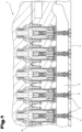
- According to 1 and 2 has a print head 1 according to the invention for an inkjet printer, at least one ink supply channel 2 and at least one nozzle 3 for ejecting the ink from the ink supply channel 2 .
- the ink channels, nozzles 3 and tappets 6 are designed or arranged like the ink channel 2, nozzle 3 and tappet 6 described below.
- the ink channel 2 is used to supply ink to the nozzle 3.
- the ink can flow continuously through the ink channel 2 in order to avoid sedimentation of the ink.
- the pressure drop in the ink channel 2 is favorably very low, which can be achieved by the largest possible cross section of the ink channel.
- the nozzle 3 is arranged in a fixed position on a side wall 4 of the ink supply channel 2 and in the ink supply channel 2 there is a plunger 6 that can be moved back and forth between two reversal points opposite the inflow opening of the nozzle, a reversal point (U1) and a reversal point (U2).
- the nozzle 3 can be arranged on the side wall 4 in an exchangeable manner, for example the nozzle 3 can be screwed into the side wall 4 of the ink supply channel 2 .
- the nozzle 3 can be made of ceramic, hard metal, glass, etc.
- An end face 7 of the nozzle 3 that has the inflow opening 5 can be formed flush with an inner surface 8 of the side wall 4 of the ink supply channel 2 that is in contact with the ink. Due to the flush design of the nozzles 3 on their inner end faces 7 with the inner wall of the ink channel 2, the flow of ink is disturbed as little as possible and sedimentation is avoided.
- a longitudinal center axis a of the nozzle 3 can here run normal to the surface 8 of the ink supply channel 2 .
- a section of the ram 6 opposite an end face 9 of the ram 6 can be fixedly connected to a movable ram rod 10 which is acted upon by a restoring force acting in the direction of the nozzle 3 .
- the plunger 6 can be pulled back from the nozzle by means of an actuator.
- An electromechanical actuator for example in the form of a magnet armature 11 which is connected to the push rod 10 and which interacts with a coil 12 which can be wound around a core 13, can be provided as the actuator for actuating the push rod.
- the plunger 6 can be pulled up by the armature 11 of the pulling magnet. In doing so, an in 1 provided with the reference numeral 14 tensioned spring, which pushes the plunger 6 back down in a currentless state of the actuator.
- the push rod 10 can be movably guided, at least in sections, in a hollow shaft 15 parallel to a central longitudinal straight line of the guide shaft or hollow shaft 15 , it being possible for a radially circumferential seal 16 to be provided between the guide rod 10 and the hollow shaft 15 .
- the guide shaft 15 can protrude into the ink channel 2 from the boundary wall 17 of the ink channel 2 lying opposite the nozzle 3 .
- the sealing of the transition between the guide shaft 15 and the plunger 6 can prevent the ink from penetrating the guide shaft 15 .
- the guide shaft 15 can be designed to be slim in order to cause as little flow resistance as possible in the ink channel. It is particularly favorable here if the guide shaft or hollow shaft 15 has a smooth and/or rounded surface.
- the guide shaft or hollow shaft 15 can have a circular, elliptical or similar cross-section, for example.
- a ceramic part or a part made of a material other than that of the plunger material can be inserted into the end face 9 of the ram in order to obtain a longer service life for the end face 9 in the presence of abrasive pigments.
- the inflow opening 5 of the nozzle 3 can be conical, in the form of a funnel tapering in the direction of an outlet opening 18 .
- the outlet opening 18 of the nozzle 3 can be cylindrical.
- the nozzle 3 can have a length L that is a multiple, but at least twice, of a maximum diameter d of the nozzle 3 .
- the inflow opening 5 of the nozzle 3 is preferably arranged in a region of the side wall 4 opposite the tappet 6, which region lies within a pump chamber 19 and delimits this in one direction.
- the pumping effect that is present and necessary in every inkjet print head which is illustrated by an imaginary pumping chamber 19 and can be formed from a cylindrical space defined by the diameter d1 of the plunger face 9 and the distance a1 from the face of the plunger to the inner face of the nozzle or to the front side of the inflow opening 5 is limited.
- this spatial area does not necessarily have to be cylindrical.
- the pumping chamber 19 is the space in which a change in volume takes place.
- the pump chamber 19 has, as in FIG 4 shown, always two openings 20 and 21, one for the inlet and one for the outlet.
- the plunger 6 moves up and ink flows through the inlet 20 and outlet opening 21 into the space of the pumping chamber 19.
- the plunger 6 moves downwards and ink flows through the inlet 20 and outlet opening 21 from the space of the pump chamber 19.
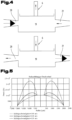
- this pressure curve has its maximum or minimum, according to 3 a cylindrical boundary surface 22 with the so-called stagnation radius rs.
- the ink flows into or out of the ink channel, within this boundary surface 22, the ink flows out of the nozzle or into the nozzle, depending on the direction of movement of the plunger 6.
- the stagnation radius rs depends on the direction of movement and speed of the plunger -ßels 6, from the distance a1 of the plunger 6 to the nozzle and from the pressure at the radius r and at the radius ri. This results in the ink volumes flowing in both directions when the plunger 6 moves up and down.
- the inflow opening 5 of the nozzle 3 can be arranged directly at the outlet opening 21 of the pump chamber 19 .
- the inflow opening 5 of the nozzle 3 is arranged in a region of the side wall 4 opposite the plunger 6, which is delimited when the plunger 6 moves by the associated pressure profile in the ink within the boundary surface 22 forming the ink.
- figure 5 shows a theoretically calculated radius-dependent pressure curve under the ram 6.
- the stagnation radius rs is where the pressure has its maximum value.
- the length L in the direction of flow is usually designed in such a way that the volume of ink in the nozzle roughly corresponds to the volume of the drop. Since the nozzle diameter of a print head for structural printers must be larger than that of standard inkjet print heads in order to achieve the required droplet volume, the capillary pressure is significantly lower and more ink is sucked back through the nozzle 3 into the pump chamber 19 during the refill cycle. For this reason, the length of the nozzle L can be significantly increased so that the nozzle cannot be completely emptied during the refill cycle and air enters the pumping chamber 19.
- the length L of the nozzle consists of the lengths for the cylindrical part 12 and for the conical part 11.
- these or their components are sometimes not to scale and/or enlarged. have been shown enlarged and/or reduced.
- a plurality of ink supply channels 2 are aligned parallel to one another lengthwise in a print head, in each of which a plurality of nozzles 3 with nozzle channel and inflow opening 5 are preferably arranged at equal intervals on the ink supply channel wall.
- First means 23, such as at least one actuator or at least one actuator and at least one spring are provided for the movement of a ram face 9 or the ram 6, which limit the ram face 9 to a movement between the reversal points (U1, U2).
- Second external means such as a vacuum pump, e.g.
- an intermediate ink tank which is connected to the print head via at least one ink supply line, and which pump is arranged in the air space above a liquid level, is used to apply a negative pressure relative to the ink in the ink supply channel 2 provided to the ambient air pressure.
- Third external means such as a circulating pump, is provided, for example, in an intermediate ink tank, which pumps the ink, preferably permanently, through the at least one ink supply line and ink supply channels of the print head.
- the ink in the ink supply channel 2 is subjected to a negative pressure in the range from greater than zero to preferably 5 mbar relative to the ambient pressure with a nozzle inside diameter at the outlet opening of the nozzle of 300 ⁇ m.
- a negative pressure in the range from greater than zero to preferably 5 mbar relative to the ambient pressure means a pressure which is smaller than the ambient air pressure in the range from greater than zero to 5 mbar.
- the ink delivery quantity "X" pumped through the ink supply channel per time unit is greater by a specific factor adapted to the system than the sum of the ink quantity that is pumped during the printing operation can be ejected at most through all nozzles, whereby the rule always applies that the ink pressure in combination with the capillary pressure must be set in such a way that no air is sucked through the nozzle channel into the ink supply channel and that no ink escapes from the nozzle channel unintentionally.
- the plunger 6 is arranged in a non-sealing manner in the ink supply channel 2 on an ink channel wall, with a distance from the outer edge of the plunger to a side wall of the ink supply channel in a direction vertical to the nozzle axis preferably being greater than 1 mm and more preferably greater than 3 mm.
- the plunger 6 has an outside diameter of preferably between 3.0 and 5.0 mm.
- the nozzle 3 has an inside diameter of preferably between 200 and 350 ⁇ m.
- the change in direction at the reversal point (U1) has a frequency of preferably up to 1.1 kHz and more preferably up to 1.0 kHz. If the outside diameter of the ram is smaller, you can print with far higher frequencies.
- the ram/nozzle distance at the reversal point (U1) is greater than zero and preferably up to 100 ⁇ m and the ram/nozzle distance at the reversal point (U2) is greater than 250 ⁇ m and preferably up to 400 ⁇ m.
- At least one ram/nozzle distance at a reversal point should be at least larger than the corresponding particle size "g" in order to avoid collisions of the ram with to avoid the pigments that may be present on the nozzle surface.
- a plurality of printheads can be mounted in a staggered or any other arrangement and thereby arranged such that in the printing process at least one nozzle of one printhead overlaps with at least one nozzle of another printhead in at least one direction and/or that the nozzles of one Row of nozzles of a print head are shifted relative to the nozzles of a row of nozzles of another print head by a certain nozzle distance from each other.
- the nozzle rows of the print heads can be set parallel to one another and at an angle with respect to a sub-scanning direction Y, so that the nozzle spacing between the individual nozzles is
- Print head has a nozzle spacing Y in a main printing direction X, so that one can print in the main scanning direction X with a higher resolution than with the native resolution of a print head.
Landscapes
- Ink Jet (AREA)
- Particle Formation And Scattering Control In Inkjet Printers (AREA)
Priority Applications (1)
| Application Number | Priority Date | Filing Date | Title |
|---|---|---|---|
| PL12735287.0T PL2734371T6 (pl) | 2011-07-22 | 2012-07-11 | Głowica drukująca dla drukarki atramentowej |
Applications Claiming Priority (2)
| Application Number | Priority Date | Filing Date | Title |
|---|---|---|---|
| AT10812011 | 2011-07-22 | ||
| PCT/EP2012/063582 WO2013013983A1 (de) | 2011-07-22 | 2012-07-11 | Druckkopf für einen tintenstrahldrucker |
Publications (3)
| Publication Number | Publication Date |
|---|---|
| EP2734371A1 EP2734371A1 (de) | 2014-05-28 |
| EP2734371B1 EP2734371B1 (de) | 2015-08-26 |
| EP2734371B3 true EP2734371B3 (de) | 2023-08-23 |
Family
ID=46513760
Family Applications (1)
| Application Number | Title | Priority Date | Filing Date |
|---|---|---|---|
| EP12735287.0A Active EP2734371B3 (de) | 2011-07-22 | 2012-07-11 | Druckkopf für einen tintenstrahldrucker |
Country Status (7)
Families Citing this family (21)
| Publication number | Priority date | Publication date | Assignee | Title |
|---|---|---|---|---|
| DE102013006106A1 (de) * | 2013-04-09 | 2014-10-09 | Delo Industrie Klebstoffe Gmbh & Co. Kgaa | Dosiervorrichtung |
| US10391695B2 (en) * | 2014-04-11 | 2019-08-27 | Brian L. Douglass | Retracting extruder barrel with cooling features |
| EP3000602B1 (en) * | 2014-09-26 | 2020-07-22 | Agfa Nv | High viscosity jetting method |
| BR112017008529B1 (pt) | 2015-01-29 | 2022-01-25 | Hewlett-Packard Development Company, Lp | Método, mídia legível por computador não transitória e sistema de impressão |
| ITUB20151950A1 (it) * | 2015-07-08 | 2017-01-08 | System Spa | Dispositivo attuatore, in particolare per una testina di stampa a getto di inchiostro, con isolamento elettromagnetico |
| FR3048624B1 (fr) | 2016-03-10 | 2018-03-09 | Seb S.A. | Procede de fabrication d'un revetement thermostable par impression digitale |
| IT201700098731A1 (it) | 2017-09-04 | 2019-03-04 | Durst Phototechnik Ag | "Dispositivo per il posizionamento di un attuatore" |
| IT201700098743A1 (it) | 2017-09-04 | 2019-03-04 | Durst Phototechnik Ag | "Attuatore per una testina di stampa" |
| DE102017122495A1 (de) | 2017-09-27 | 2019-03-28 | Dürr Systems Ag | Applikator mit einem geringen Düsenabstand |
| DE102017122488A1 (de) * | 2017-09-27 | 2019-03-28 | Dürr Systems Ag | Applikator mit einer Dichtungsmembran |
| DE102017122493A1 (de) | 2017-09-27 | 2019-03-28 | Dürr Systems Ag | Applikator mit geringem Düsenabstand |
| JP7271956B2 (ja) * | 2018-01-16 | 2023-05-12 | 株式会社リコー | 弁型ノズル及び液体を吐出する装置 |
| EP3689842B1 (de) | 2019-01-31 | 2021-07-28 | Durst Phototechnik AG | Glasursuspension |
| PL4031340T3 (pl) | 2019-09-20 | 2024-07-29 | Durst Group Ag | Sposób wytwarzania reliefowego dekoru na powierzchni ceramicznego nośnika druku |
| WO2021052627A1 (de) | 2019-09-20 | 2021-03-25 | Durst Phototechnik Ag | Verfahren zum erzeugen eines reliefartigen dekors auf einer oberfläche eines keramischen druckmediums mittels partikelauftrag |
| DE102019217358A1 (de) * | 2019-11-11 | 2021-05-12 | Robert Bosch Gmbh | Druckkopf für 3D-Drucker mit agiler Druckausübung auf das Ausgangsmaterial |
| AT522763B1 (de) * | 2019-12-05 | 2021-01-15 | Metallconcept Gmbh | Druckkopf |
| CN113103773B (zh) * | 2021-02-27 | 2023-11-14 | 范建波 | 一种服装面料的印花装置 |
| IT202200003539A1 (it) | 2022-02-25 | 2023-08-25 | D3 Am Gmbh | "Metodo per strutturare un oggetto tridimensionale strato per strato" |
| IT202300004104A1 (it) | 2023-03-08 | 2024-09-08 | Durst Group Ag | "Testina di stampa per una stampante a getto d'inchiostro, in particolare per il rivestimento di supporti di stampa" |
| IT202300006870A1 (it) | 2023-04-07 | 2024-10-07 | Durst Group Ag | "Struttura di supporto per Material Jetting" |
Family Cites Families (21)
| Publication number | Priority date | Publication date | Assignee | Title |
|---|---|---|---|---|
| DE3302617C2 (de) * | 1983-01-27 | 1987-04-23 | Domino Printing Sciences Plc, Cambridge | Farbspritzkopf |
| FR2608097B1 (fr) * | 1986-12-12 | 1994-04-08 | Markpoint System Ab | Dispositif a clapet pour imprimantes matricielles |
| JPH01229640A (ja) * | 1988-03-11 | 1989-09-13 | Yoshimichi Yonezawa | レリーフ像の作製方法 |
| JPH02102053A (ja) * | 1988-10-11 | 1990-04-13 | Seiko Epson Corp | インクジェットヘッド |
| US5602575A (en) * | 1988-11-05 | 1997-02-11 | Rea Elektronik Gmbh | Ink jet writing head |
| DE3837680A1 (de) | 1988-11-05 | 1990-05-10 | Rea Elektronik Gmbh | Tintenstrahl-schreibkopf |
| JPH03281252A (ja) * | 1990-03-29 | 1991-12-11 | Matsushita Electric Ind Co Ltd | 液滴吐出装置 |
| JPH06255108A (ja) * | 1993-03-05 | 1994-09-13 | Sharp Corp | インクジェットプリンタのインク噴射ヘッド |
| JPH07125199A (ja) * | 1993-11-08 | 1995-05-16 | Silk Giken Kk | インクジェットプリンタ用ヘッド |
| GB9601947D0 (en) | 1996-01-31 | 1996-04-03 | Neopost Ltd | Ink jet printing device |
| SE507821C2 (sv) * | 1996-04-15 | 1998-07-20 | Jetline Ab | Ventilkonstruktion vid bläckstråleskrivare |
| JP2000177121A (ja) * | 1998-12-17 | 2000-06-27 | Fuji Photo Film Co Ltd | インクジェットヘッド |
| JP2002301414A (ja) * | 2001-04-10 | 2002-10-15 | Matsushita Electric Ind Co Ltd | 流体吐出方法及び流体吐出装置 |
| JP2005088294A (ja) * | 2003-09-16 | 2005-04-07 | Nidec Copal Corp | 硬化剤吐出装置及び印刷システム |
| JP2005153247A (ja) * | 2003-11-25 | 2005-06-16 | Kubota Matsushitadenko Exterior Works Ltd | インクジェット装置 |
| JP2007230061A (ja) * | 2006-02-28 | 2007-09-13 | Fujifilm Corp | インクジェット記録装置 |
| JP2008036930A (ja) * | 2006-08-04 | 2008-02-21 | Konica Minolta Medical & Graphic Inc | インクジェット記録方法 |
| ATE508875T1 (de) | 2006-10-12 | 2011-05-15 | The Technology Partnership Plc | Flüssigkeitsausstossvorrichtung |
| GB0620436D0 (en) | 2006-10-14 | 2006-11-22 | Cyden Ltd | Apparatus and method for stimulation of cartilage |
| JP2008230137A (ja) * | 2007-03-22 | 2008-10-02 | Fujifilm Corp | 液体吐出ヘッドの背圧調整装置 |
| KR101065265B1 (ko) * | 2009-06-01 | 2011-09-16 | 한국기계연구원 | 잉크 공급 및 압력조절 통합장치 |
-
2012
- 2012-07-11 JP JP2014520610A patent/JP6133857B2/ja active Active
- 2012-07-11 WO PCT/EP2012/063582 patent/WO2013013983A1/de active Application Filing
- 2012-07-11 PL PL12735287.0T patent/PL2734371T6/pl unknown
- 2012-07-11 CN CN201280036261.8A patent/CN103826858B/zh active Active
- 2012-07-11 EP EP12735287.0A patent/EP2734371B3/de active Active
- 2012-07-11 US US14/233,933 patent/US20140192117A1/en not_active Abandoned
- 2012-07-11 ES ES12735287T patent/ES2553749T7/es active Active
-
2015
- 2015-08-27 US US14/837,378 patent/US9751313B2/en active Active
-
2017
- 2017-07-05 US US15/641,745 patent/US9994029B2/en active Active
Also Published As
| Publication number | Publication date |
|---|---|
| JP2014520689A (ja) | 2014-08-25 |
| US20150360472A1 (en) | 2015-12-17 |
| ES2553749T3 (es) | 2015-12-11 |
| EP2734371B1 (de) | 2015-08-26 |
| JP6133857B2 (ja) | 2017-05-24 |
| WO2013013983A1 (de) | 2013-01-31 |
| EP2734371A1 (de) | 2014-05-28 |
| ES2553749T7 (es) | 2024-04-23 |
| CN103826858A (zh) | 2014-05-28 |
| US9751313B2 (en) | 2017-09-05 |
| US20140192117A1 (en) | 2014-07-10 |
| CN103826858B (zh) | 2016-08-17 |
| PL2734371T6 (pl) | 2024-12-02 |
| PL2734371T3 (pl) | 2016-04-29 |
| US20170297340A1 (en) | 2017-10-19 |
| US9994029B2 (en) | 2018-06-12 |
Similar Documents
| Publication | Publication Date | Title |
|---|---|---|
| EP2734371B3 (de) | Druckkopf für einen tintenstrahldrucker | |
| DE69702384T2 (de) | Flüssigkeitsversorgungsvorrichtung | |
| EP2118542B1 (de) | Mikroventil | |
| DE69714095T2 (de) | Tintenstrahldruckgerät | |
| EP0556566B1 (de) | Vorrichtung zum dosierten Zuführen einer Analyseflüssigkeit | |
| EP2900390B1 (de) | Dosiersystem, dosierverfahren und herstellungsverfahren | |
| EP3902635B1 (de) | Jet-dosierventil | |
| EP3535063B1 (de) | Druckkopf zur applikation eines beschichtungsmittels auf ein bauteil | |
| WO2005016534A1 (de) | Mikrodosiervorrichtung und verfahren zur dosierten abgabe von flüssigkeiten | |
| DE202012013612U1 (de) | Abgabevorrichtung nach dem Verdrängungsprinzip zur Abgabe diskreter Flüssigkeitsmengen | |
| DE102014013158A1 (de) | Freistrahl-Einrichtung | |
| EP2165769A2 (de) | Austragvorrichtung | |
| EP2065100B1 (de) | Trennmittelsprühvorrichtung für eine Gießmaschine. | |
| EP3687699B1 (de) | Applikator mit einer dichtungsmembran | |
| WO2014048642A1 (de) | Dosiersystem, dosierverfahren und herstellungsverfahren | |
| WO2019063668A1 (de) | Applikator mit einem geringen düsenabstand | |
| WO1999004975A2 (de) | Verfahren und vorrichtung zum abdecken und reinigen der düsen eines tintendruckkopfes | |
| EP2945754B1 (de) | Dosiervorrichtung | |
| EP3362671B1 (de) | Piezo-injektor zur kraftstoffeinspritzung | |
| DE102013224453A1 (de) | Ventil zur Dosierung von Medien im Kleinstmengenbereich | |
| WO2024183949A1 (de) | Druckkopf für einen tintenstahldrucker, insbesondere zum beschichten von druckmedien | |
| DE10218546A1 (de) | Kraftstoffeinspritzvorrichtung zum Anheben eines Nadelventils mit variabler Geschwindigkeit | |
| DE102021100754A1 (de) | Dosierventil | |
| EP2716459B1 (de) | Tintenstrahl-Schreibkopf mit Dichtelement | |
| EP1757807A1 (de) | Mikrodosiersystem |
Legal Events
| Date | Code | Title | Description |
|---|---|---|---|
| PUAI | Public reference made under article 153(3) epc to a published international application that has entered the european phase |
Free format text: ORIGINAL CODE: 0009012 |
|
| 17P | Request for examination filed |
Effective date: 20140220 |
|
| AK | Designated contracting states |
Kind code of ref document: A1 Designated state(s): AL AT BE BG CH CY CZ DE DK EE ES FI FR GB GR HR HU IE IS IT LI LT LU LV MC MK MT NL NO PL PT RO RS SE SI SK SM TR |
|
| DAX | Request for extension of the european patent (deleted) | ||
| GRAP | Despatch of communication of intention to grant a patent |
Free format text: ORIGINAL CODE: EPIDOSNIGR1 |
|
| INTG | Intention to grant announced |
Effective date: 20150407 |
|
| GRAS | Grant fee paid |
Free format text: ORIGINAL CODE: EPIDOSNIGR3 |
|
| GRAA | (expected) grant |
Free format text: ORIGINAL CODE: 0009210 |
|
| RIN1 | Information on inventor provided before grant (corrected) |
Inventor name: OBERTEGGER, FRANZ |
|
| AK | Designated contracting states |
Kind code of ref document: B1 Designated state(s): AL AT BE BG CH CY CZ DE DK EE ES FI FR GB GR HR HU IE IS IT LI LT LU LV MC MK MT NL NO PL PT RO RS SE SI SK SM TR |
|
| REG | Reference to a national code |
Ref country code: GB Ref legal event code: FG4D Free format text: NOT ENGLISH |
|
| REG | Reference to a national code |
Ref country code: CH Ref legal event code: EP |
|
| REG | Reference to a national code |
Ref country code: AT Ref legal event code: REF Ref document number: 744935 Country of ref document: AT Kind code of ref document: T Effective date: 20150915 |
|
| REG | Reference to a national code |
Ref country code: IE Ref legal event code: FG4D Free format text: LANGUAGE OF EP DOCUMENT: GERMAN |
|
| REG | Reference to a national code |
Ref country code: DE Ref legal event code: R096 Ref document number: 502012004319 Country of ref document: DE |
|
| REG | Reference to a national code |
Ref country code: ES Ref legal event code: FG2A Ref document number: 2553749 Country of ref document: ES Kind code of ref document: T3 Effective date: 20151211 |
|
| REG | Reference to a national code |
Ref country code: LT Ref legal event code: MG4D |
|
| PG25 | Lapsed in a contracting state [announced via postgrant information from national office to epo] |
Ref country code: LT Free format text: LAPSE BECAUSE OF FAILURE TO SUBMIT A TRANSLATION OF THE DESCRIPTION OR TO PAY THE FEE WITHIN THE PRESCRIBED TIME-LIMIT Effective date: 20150826 Ref country code: GR Free format text: LAPSE BECAUSE OF FAILURE TO SUBMIT A TRANSLATION OF THE DESCRIPTION OR TO PAY THE FEE WITHIN THE PRESCRIBED TIME-LIMIT Effective date: 20151127 Ref country code: FI Free format text: LAPSE BECAUSE OF FAILURE TO SUBMIT A TRANSLATION OF THE DESCRIPTION OR TO PAY THE FEE WITHIN THE PRESCRIBED TIME-LIMIT Effective date: 20150826 Ref country code: LV Free format text: LAPSE BECAUSE OF FAILURE TO SUBMIT A TRANSLATION OF THE DESCRIPTION OR TO PAY THE FEE WITHIN THE PRESCRIBED TIME-LIMIT Effective date: 20150826 Ref country code: NO Free format text: LAPSE BECAUSE OF FAILURE TO SUBMIT A TRANSLATION OF THE DESCRIPTION OR TO PAY THE FEE WITHIN THE PRESCRIBED TIME-LIMIT Effective date: 20151126 |
|
| REG | Reference to a national code |
Ref country code: NL Ref legal event code: MP Effective date: 20150826 |
|
| PG25 | Lapsed in a contracting state [announced via postgrant information from national office to epo] |
Ref country code: SE Free format text: LAPSE BECAUSE OF FAILURE TO SUBMIT A TRANSLATION OF THE DESCRIPTION OR TO PAY THE FEE WITHIN THE PRESCRIBED TIME-LIMIT Effective date: 20150826 Ref country code: PT Free format text: LAPSE BECAUSE OF FAILURE TO SUBMIT A TRANSLATION OF THE DESCRIPTION OR TO PAY THE FEE WITHIN THE PRESCRIBED TIME-LIMIT Effective date: 20151228 Ref country code: RS Free format text: LAPSE BECAUSE OF FAILURE TO SUBMIT A TRANSLATION OF THE DESCRIPTION OR TO PAY THE FEE WITHIN THE PRESCRIBED TIME-LIMIT Effective date: 20150826 Ref country code: HR Free format text: LAPSE BECAUSE OF FAILURE TO SUBMIT A TRANSLATION OF THE DESCRIPTION OR TO PAY THE FEE WITHIN THE PRESCRIBED TIME-LIMIT Effective date: 20150826 Ref country code: IS Free format text: LAPSE BECAUSE OF FAILURE TO SUBMIT A TRANSLATION OF THE DESCRIPTION OR TO PAY THE FEE WITHIN THE PRESCRIBED TIME-LIMIT Effective date: 20151226 |
|
| PG25 | Lapsed in a contracting state [announced via postgrant information from national office to epo] |
Ref country code: NL Free format text: LAPSE BECAUSE OF FAILURE TO SUBMIT A TRANSLATION OF THE DESCRIPTION OR TO PAY THE FEE WITHIN THE PRESCRIBED TIME-LIMIT Effective date: 20150826 |
|
| PG25 | Lapsed in a contracting state [announced via postgrant information from national office to epo] |
Ref country code: EE Free format text: LAPSE BECAUSE OF FAILURE TO SUBMIT A TRANSLATION OF THE DESCRIPTION OR TO PAY THE FEE WITHIN THE PRESCRIBED TIME-LIMIT Effective date: 20150826 Ref country code: CZ Free format text: LAPSE BECAUSE OF FAILURE TO SUBMIT A TRANSLATION OF THE DESCRIPTION OR TO PAY THE FEE WITHIN THE PRESCRIBED TIME-LIMIT Effective date: 20150826 Ref country code: SK Free format text: LAPSE BECAUSE OF FAILURE TO SUBMIT A TRANSLATION OF THE DESCRIPTION OR TO PAY THE FEE WITHIN THE PRESCRIBED TIME-LIMIT Effective date: 20150826 Ref country code: DK Free format text: LAPSE BECAUSE OF FAILURE TO SUBMIT A TRANSLATION OF THE DESCRIPTION OR TO PAY THE FEE WITHIN THE PRESCRIBED TIME-LIMIT Effective date: 20150826 |
|
| REG | Reference to a national code |
Ref country code: DE Ref legal event code: R097 Ref document number: 502012004319 Country of ref document: DE |
|
| PG25 | Lapsed in a contracting state [announced via postgrant information from national office to epo] |
Ref country code: RO Free format text: LAPSE BECAUSE OF FAILURE TO SUBMIT A TRANSLATION OF THE DESCRIPTION OR TO PAY THE FEE WITHIN THE PRESCRIBED TIME-LIMIT Effective date: 20150826 |
|
| PLBE | No opposition filed within time limit |
Free format text: ORIGINAL CODE: 0009261 |
|
| REG | Reference to a national code |
Ref country code: FR Ref legal event code: PLFP Year of fee payment: 5 |
|
| 26N | No opposition filed |
Effective date: 20160530 |
|
| PG25 | Lapsed in a contracting state [announced via postgrant information from national office to epo] |
Ref country code: SI Free format text: LAPSE BECAUSE OF FAILURE TO SUBMIT A TRANSLATION OF THE DESCRIPTION OR TO PAY THE FEE WITHIN THE PRESCRIBED TIME-LIMIT Effective date: 20150826 |
|
| PG25 | Lapsed in a contracting state [announced via postgrant information from national office to epo] |
Ref country code: BE Free format text: LAPSE BECAUSE OF NON-PAYMENT OF DUE FEES Effective date: 20160731 |
|
| REG | Reference to a national code |
Ref country code: CH Ref legal event code: PL |
|
| PG25 | Lapsed in a contracting state [announced via postgrant information from national office to epo] |
Ref country code: MC Free format text: LAPSE BECAUSE OF FAILURE TO SUBMIT A TRANSLATION OF THE DESCRIPTION OR TO PAY THE FEE WITHIN THE PRESCRIBED TIME-LIMIT Effective date: 20150826 |
|
| PG25 | Lapsed in a contracting state [announced via postgrant information from national office to epo] |
Ref country code: LI Free format text: LAPSE BECAUSE OF NON-PAYMENT OF DUE FEES Effective date: 20160731 Ref country code: CH Free format text: LAPSE BECAUSE OF NON-PAYMENT OF DUE FEES Effective date: 20160731 |
|
| REG | Reference to a national code |
Ref country code: IE Ref legal event code: MM4A |
|
| REG | Reference to a national code |
Ref country code: FR Ref legal event code: PLFP Year of fee payment: 6 |
|
| PG25 | Lapsed in a contracting state [announced via postgrant information from national office to epo] |
Ref country code: IE Free format text: LAPSE BECAUSE OF NON-PAYMENT OF DUE FEES Effective date: 20160711 |
|
| PG25 | Lapsed in a contracting state [announced via postgrant information from national office to epo] |
Ref country code: LU Free format text: LAPSE BECAUSE OF NON-PAYMENT OF DUE FEES Effective date: 20160711 |
|
| PG25 | Lapsed in a contracting state [announced via postgrant information from national office to epo] |
Ref country code: CY Free format text: LAPSE BECAUSE OF FAILURE TO SUBMIT A TRANSLATION OF THE DESCRIPTION OR TO PAY THE FEE WITHIN THE PRESCRIBED TIME-LIMIT Effective date: 20150826 Ref country code: SM Free format text: LAPSE BECAUSE OF FAILURE TO SUBMIT A TRANSLATION OF THE DESCRIPTION OR TO PAY THE FEE WITHIN THE PRESCRIBED TIME-LIMIT Effective date: 20150826 Ref country code: HU Free format text: LAPSE BECAUSE OF FAILURE TO SUBMIT A TRANSLATION OF THE DESCRIPTION OR TO PAY THE FEE WITHIN THE PRESCRIBED TIME-LIMIT; INVALID AB INITIO Effective date: 20120711 |
|
| REG | Reference to a national code |
Ref country code: FR Ref legal event code: PLFP Year of fee payment: 7 |
|
| PG25 | Lapsed in a contracting state [announced via postgrant information from national office to epo] |
Ref country code: MT Free format text: LAPSE BECAUSE OF FAILURE TO SUBMIT A TRANSLATION OF THE DESCRIPTION OR TO PAY THE FEE WITHIN THE PRESCRIBED TIME-LIMIT Effective date: 20150826 Ref country code: MK Free format text: LAPSE BECAUSE OF FAILURE TO SUBMIT A TRANSLATION OF THE DESCRIPTION OR TO PAY THE FEE WITHIN THE PRESCRIBED TIME-LIMIT Effective date: 20150826 |
|
| REG | Reference to a national code |
Ref country code: DE Ref legal event code: R082 Ref document number: 502012004319 Country of ref document: DE Representative=s name: ABP BURGER RECHTSANWALTSGESELLSCHAFT MBH, DE |
|
| PG25 | Lapsed in a contracting state [announced via postgrant information from national office to epo] |
Ref country code: BG Free format text: LAPSE BECAUSE OF FAILURE TO SUBMIT A TRANSLATION OF THE DESCRIPTION OR TO PAY THE FEE WITHIN THE PRESCRIBED TIME-LIMIT Effective date: 20150826 |
|
| PG25 | Lapsed in a contracting state [announced via postgrant information from national office to epo] |
Ref country code: AL Free format text: LAPSE BECAUSE OF FAILURE TO SUBMIT A TRANSLATION OF THE DESCRIPTION OR TO PAY THE FEE WITHIN THE PRESCRIBED TIME-LIMIT Effective date: 20150826 |
|
| REG | Reference to a national code |
Ref country code: DE Ref legal event code: R055 Ref document number: 502012004319 Country of ref document: DE |
|
| PLCP | Request for limitation filed |
Free format text: ORIGINAL CODE: EPIDOSNLIM1 |
|
| PLCQ | Request for limitation of patent found admissible |
Free format text: ORIGINAL CODE: 0009231 |
|
| LIM1 | Request for limitation found admissible |
Free format text: SEQUENCE NO: 1; FILED AFTER OPPOSITION PERIOD Filing date: 20230317 |
|
| REG | Reference to a national code |
Ref country code: DE Ref legal event code: R056 Ref document number: 502012004319 Country of ref document: DE |
|
| P01 | Opt-out of the competence of the unified patent court (upc) registered |
Effective date: 20230523 |
|
| PLCR | Communication despatched that request for limitation of patent was allowed |
Free format text: ORIGINAL CODE: 0009245 |
|
| PLCN | Payment of fee for limitation of patent |
Free format text: ORIGINAL CODE: EPIDOSNRAL3 |
|
| PUAM | (expected) publication of b3 document |
Free format text: ORIGINAL CODE: 0009410 |
|
| STAA | Information on the status of an ep patent application or granted ep patent |
Free format text: STATUS: THE PATENT HAS BEEN LIMITED |
|
| REG | Reference to a national code |
Ref country code: DE Ref legal event code: R081 Ref document number: 502012004319 Country of ref document: DE Owner name: DURST GROUP A.G., IT Free format text: FORMER OWNER: DURST PHOTOTECHNIK A.G., BRIXEN, IT |
|
| REG | Reference to a national code |
Ref country code: AT Ref legal event code: HC Ref document number: 744935 Country of ref document: AT Kind code of ref document: T Owner name: DURST GROUP A.G., IT Effective date: 20231227 |
|
| PGFP | Annual fee paid to national office [announced via postgrant information from national office to epo] |
Ref country code: DE Payment date: 20240719 Year of fee payment: 13 |
|
| PGFP | Annual fee paid to national office [announced via postgrant information from national office to epo] |
Ref country code: GB Payment date: 20240723 Year of fee payment: 13 |
|
| PGFP | Annual fee paid to national office [announced via postgrant information from national office to epo] |
Ref country code: FR Payment date: 20240717 Year of fee payment: 13 |
|
| PGFP | Annual fee paid to national office [announced via postgrant information from national office to epo] |
Ref country code: ES Payment date: 20240816 Year of fee payment: 13 |
|
| PGFP | Annual fee paid to national office [announced via postgrant information from national office to epo] |
Ref country code: AT Payment date: 20240718 Year of fee payment: 13 |
|
| PGFP | Annual fee paid to national office [announced via postgrant information from national office to epo] |
Ref country code: IT Payment date: 20240731 Year of fee payment: 13 |
|
| PGFP | Annual fee paid to national office [announced via postgrant information from national office to epo] |
Ref country code: TR Payment date: 20240702 Year of fee payment: 13 |
|
| PGFP | Annual fee paid to national office [announced via postgrant information from national office to epo] |
Ref country code: PL Payment date: 20250627 Year of fee payment: 14 |