EP2733342A1 - Luftfilteranordnung für ein Arbeitsfahrzeug - Google Patents
Luftfilteranordnung für ein Arbeitsfahrzeug Download PDFInfo
- Publication number
- EP2733342A1 EP2733342A1 EP13191421.0A EP13191421A EP2733342A1 EP 2733342 A1 EP2733342 A1 EP 2733342A1 EP 13191421 A EP13191421 A EP 13191421A EP 2733342 A1 EP2733342 A1 EP 2733342A1
- Authority
- EP
- European Patent Office
- Prior art keywords
- shroud
- air filter
- air
- fan
- inlet
- Prior art date
- Legal status (The legal status is an assumption and is not a legal conclusion. Google has not performed a legal analysis and makes no representation as to the accuracy of the status listed.)
- Granted
Links
- 239000012530 fluid Substances 0.000 claims description 8
- 238000004891 communication Methods 0.000 claims description 2
- 238000001816 cooling Methods 0.000 description 11
- 238000004140 cleaning Methods 0.000 description 7
- 239000000446 fuel Substances 0.000 description 3
- 238000009428 plumbing Methods 0.000 description 3
- 238000001914 filtration Methods 0.000 description 2
- 238000012986 modification Methods 0.000 description 2
- 230000004048 modification Effects 0.000 description 2
- 239000013618 particulate matter Substances 0.000 description 2
- 230000005540 biological transmission Effects 0.000 description 1
- 238000002485 combustion reaction Methods 0.000 description 1
- 238000013461 design Methods 0.000 description 1
- 239000000428 dust Substances 0.000 description 1
- 230000006870 function Effects 0.000 description 1
- 239000000463 material Substances 0.000 description 1
- 238000000034 method Methods 0.000 description 1
- 238000002156 mixing Methods 0.000 description 1
- 239000010705 motor oil Substances 0.000 description 1
- 230000003071 parasitic effect Effects 0.000 description 1
- 238000012546 transfer Methods 0.000 description 1
- 230000007704 transition Effects 0.000 description 1
Images


Classifications
-
- F—MECHANICAL ENGINEERING; LIGHTING; HEATING; WEAPONS; BLASTING
- F01—MACHINES OR ENGINES IN GENERAL; ENGINE PLANTS IN GENERAL; STEAM ENGINES
- F01P—COOLING OF MACHINES OR ENGINES IN GENERAL; COOLING OF INTERNAL-COMBUSTION ENGINES
- F01P11/00—Component parts, details, or accessories not provided for in, or of interest apart from, groups F01P1/00 - F01P9/00
- F01P11/12—Filtering, cooling, or silencing cooling-air
-
- B—PERFORMING OPERATIONS; TRANSPORTING
- B60—VEHICLES IN GENERAL
- B60K—ARRANGEMENT OR MOUNTING OF PROPULSION UNITS OR OF TRANSMISSIONS IN VEHICLES; ARRANGEMENT OR MOUNTING OF PLURAL DIVERSE PRIME-MOVERS IN VEHICLES; AUXILIARY DRIVES FOR VEHICLES; INSTRUMENTATION OR DASHBOARDS FOR VEHICLES; ARRANGEMENTS IN CONNECTION WITH COOLING, AIR INTAKE, GAS EXHAUST OR FUEL SUPPLY OF PROPULSION UNITS IN VEHICLES
- B60K11/00—Arrangement in connection with cooling of propulsion units
- B60K11/06—Arrangement in connection with cooling of propulsion units with air cooling
-
- F—MECHANICAL ENGINEERING; LIGHTING; HEATING; WEAPONS; BLASTING
- F02—COMBUSTION ENGINES; HOT-GAS OR COMBUSTION-PRODUCT ENGINE PLANTS
- F02M—SUPPLYING COMBUSTION ENGINES IN GENERAL WITH COMBUSTIBLE MIXTURES OR CONSTITUENTS THEREOF
- F02M35/00—Combustion-air cleaners, air intakes, intake silencers, or induction systems specially adapted for, or arranged on, internal-combustion engines
- F02M35/02—Air cleaners
- F02M35/04—Air cleaners specially arranged with respect to engine, to intake system or specially adapted to vehicle; Mounting thereon ; Combinations with other devices
- F02M35/06—Air cleaners specially arranged with respect to engine, to intake system or specially adapted to vehicle; Mounting thereon ; Combinations with other devices combined or associated with engine's cooling blower or fan, or with flywheel
-
- F—MECHANICAL ENGINEERING; LIGHTING; HEATING; WEAPONS; BLASTING
- F02—COMBUSTION ENGINES; HOT-GAS OR COMBUSTION-PRODUCT ENGINE PLANTS
- F02M—SUPPLYING COMBUSTION ENGINES IN GENERAL WITH COMBUSTIBLE MIXTURES OR CONSTITUENTS THEREOF
- F02M35/00—Combustion-air cleaners, air intakes, intake silencers, or induction systems specially adapted for, or arranged on, internal-combustion engines
- F02M35/16—Combustion-air cleaners, air intakes, intake silencers, or induction systems specially adapted for, or arranged on, internal-combustion engines characterised by use in vehicles
- F02M35/161—Arrangement of the air intake system in the engine compartment, e.g. with respect to the bonnet or the vehicle front face
-
- F—MECHANICAL ENGINEERING; LIGHTING; HEATING; WEAPONS; BLASTING
- F02—COMBUSTION ENGINES; HOT-GAS OR COMBUSTION-PRODUCT ENGINE PLANTS
- F02M—SUPPLYING COMBUSTION ENGINES IN GENERAL WITH COMBUSTIBLE MIXTURES OR CONSTITUENTS THEREOF
- F02M35/00—Combustion-air cleaners, air intakes, intake silencers, or induction systems specially adapted for, or arranged on, internal-combustion engines
- F02M35/16—Combustion-air cleaners, air intakes, intake silencers, or induction systems specially adapted for, or arranged on, internal-combustion engines characterised by use in vehicles
- F02M35/164—Heavy duty vehicles, e.g. trucks, trains, agricultural or construction machines
-
- F—MECHANICAL ENGINEERING; LIGHTING; HEATING; WEAPONS; BLASTING
- F01—MACHINES OR ENGINES IN GENERAL; ENGINE PLANTS IN GENERAL; STEAM ENGINES
- F01P—COOLING OF MACHINES OR ENGINES IN GENERAL; COOLING OF INTERNAL-COMBUSTION ENGINES
- F01P3/00—Liquid cooling
- F01P3/18—Arrangements or mounting of liquid-to-air heat-exchangers
-
- F—MECHANICAL ENGINEERING; LIGHTING; HEATING; WEAPONS; BLASTING
- F02—COMBUSTION ENGINES; HOT-GAS OR COMBUSTION-PRODUCT ENGINE PLANTS
- F02M—SUPPLYING COMBUSTION ENGINES IN GENERAL WITH COMBUSTIBLE MIXTURES OR CONSTITUENTS THEREOF
- F02M35/00—Combustion-air cleaners, air intakes, intake silencers, or induction systems specially adapted for, or arranged on, internal-combustion engines
- F02M35/02—Air cleaners
- F02M35/04—Air cleaners specially arranged with respect to engine, to intake system or specially adapted to vehicle; Mounting thereon ; Combinations with other devices
- F02M35/048—Arranging or mounting on or with respect to engines or vehicle bodies
-
- F—MECHANICAL ENGINEERING; LIGHTING; HEATING; WEAPONS; BLASTING
- F02—COMBUSTION ENGINES; HOT-GAS OR COMBUSTION-PRODUCT ENGINE PLANTS
- F02M—SUPPLYING COMBUSTION ENGINES IN GENERAL WITH COMBUSTIBLE MIXTURES OR CONSTITUENTS THEREOF
- F02M35/00—Combustion-air cleaners, air intakes, intake silencers, or induction systems specially adapted for, or arranged on, internal-combustion engines
- F02M35/10—Air intakes; Induction systems
- F02M35/10006—Air intakes; Induction systems characterised by the position of elements of the air intake system in direction of the air intake flow, i.e. between ambient air inlet and supply to the combustion chamber
- F02M35/10013—Means upstream of the air filter; Connection to the ambient air
Definitions
- the present subject matter relates generally to work vehicles and, more particularly, to an air filter arrangement for a work vehicle.
- work vehicles typically include a large number of under-hood components, such as the various components included within the air intake, air cleaning, fuel supply, electrical, cooling and exhaust systems of a work vehicle. As such, these components must be carefully designed to fit within the limited space of the vehicle's engine compartment.
- the air filter of the vehicle's air cleaning system is one of the last components designed into the engine compartment.
- air filters are typically engine-mounted or body-mounted where space permits.
- positioning of the air filter often requires a complex piping scheme, with large amounts of plumbing, to route dirty intake air to the air filter and cleaned air from the filter to the engine.
- an air filter arrangement for a work vehicle that reduces the total amount of plumbing required to route air from the intake location to the engine and/or that provides additional open space within the engine compartment for other under-hood components of the work vehicle.
- the present subject matter discloses an air filter arrangement for a work vehicle.
- the air filter arrangement may include a fan shroud extending between a shroud inlet and a shroud outlet and at least one heat exchanger disposed adjacent to the shroud inlet.
- the air filter arrangement may also include a fan disposed within the fan shroud between the shroud inlet and shroud outlet. The fan may be configured to draw air through the heat exchanger and between the shroud inlet and shroud outlet.
- the air filter arrangement may include an air filter disposed within the fan shroud between the fan and the heat exchanger such that the air flowing through at least one heat exchanger and between the shroud inlet and shroud outlet is directed around the air filter.
- the present subject matter discloses an air filter arrangement for a work vehicle.
- the air filter arrangement may include a fan shroud defining a shroud inlet and a shroud outlet and a fan disposed within the fan shroud between the shroud inlet and shroud outlet.
- the fan may be configured to draw air into the shroud inlet.
- the air filter arrangement may also include an air filter disposed within the fan shroud.
- the air filter may be configured to receive and filter dirty air entering a portion of the work vehicle, wherein the dirty air received by the air filter is isolated from the air being drawn into the shroud inlet.
- the present subject matter is directed to a work vehicle including an engine and a hood enclosure surrounding at least a portion of the engine.
- the hood enclosure may include a front grille.
- the work vehicle may also include a fan shroud disposed between the front grille and the engine.
- the fan shroud may include a shroud inlet and a shroud outlet.
- the work vehicle may include at least one heat exchanger disposed adjacent to the shroud inlet and a fan disposed within the fan shroud between the shroud inlet and shroud outlet.
- the fan may be configured to draw air through the heat exchanger and between the shroud inlet and shroud outlet.
- the work vehicle may include an air filter disposed within the fan shroud between the fan and the heat exchanger such that the air flowing through the heat exchanger and between the shroud inlet and shroud outlet is directed around the air filter.
- the present subject matter is directed to an air filter arrangement for a work vehicle.
- the air filter may be positioned within a fan shroud of the cooling system of the work vehicle, such as by positioning the air filter between a shroud inlet of the fan shroud and cooling fan of the work vehicle.
- the inlet and outlet ducts for the air filter may extend from the air filter to a location outside the fan shroud.
- the inlet duct may extend from the air filter and through the fan shroud to a position adjacent to the shroud inlet.
- the air entering the work vehicle may be directed through a front grille of the vehicle and into either the inlet duct of the air filter or the shroud inlet.
- FIG. 1 illustrates a side view of one embodiment of a work vehicle 10 in accordance with aspects of the present subject matter.
- the work vehicle 10 illustrated herein is configured as an agricultural tractor, the work vehicle 10 may generally be configured as any suitable work vehicle known in the art, such as various other agricultural vehicles (e.g., combines), earth-moving vehicles, road vehicles, loaders and/or the like.
- the work vehicle 10 generally include a chassis or frame 12 that is supported by a pair rear wheels 16 and a pair of front wheels 14, with the rear wheels 16 and/or front wheels 14 being configured as drive wheels.
- An operator's compartment or cab 18 may be supported along a rear portion of the frame 12 and a hood enclosure 20 may be supported along a front portion of the frame 12.
- the hood enclosure 20 may generally extend between an aft end 22 disposed adjacent to the cab 18 and a forward end 24 defining a grille 26 at the front of the work vehicle 10.
- the hood enclosure 20 may be configured to least partially surround and/or cover various under-hood components of the work vehicle 10, such as an engine 28, an engine cooling system 30 and an air cleaning system 32 of the work vehicle 10.
- hood enclosure 20 may be formed from a single panel or a plurality of different panels coupled together so as to surround and/or encase the under-hood components of the work vehicle 10.
- FIGS. 2-4 several views of various components of the cooling and air cleaning systems 30, 32 of the work vehicle 10 are illustrated in accordance with aspects of the present subject matter.
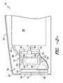
- FIG. 2 illustrates a cross-sectional, internal side view of the hood enclosure 20 of the work vehicle 10, particularly illustrating a simplified view of one embodiment of a suitable air filter arrangement for the work vehicle 10.
- FIGS. 3 and 4 illustrate front and rear perspective views, respectively, of the air filter arrangement shown in FIG. 2 .
- the cooling system 30 may generally include one or more heat exchangers 34 disposed directly adjacent to the front grille 26 of the work vehicle 10.
- the heat exchanger(s) 34 may be configured to cool the engine fluid(s) and/or the other fluid(s) utilized during operation of the work vehicle 10 by transmitting such fluid(s) through a plurality of tubes having suitable heat transfer features (e.g., cooling fins, rods, coils and/or the like) so that heat is transferred from the fluid(s) to an airflow passing over and across the tubes.
- the heat exchanger(s) 34 may comprise one or more radiators, intercoolers, fuel coolers, transmission fluid coolers, engine oil coolers and/or the like.
- the heat exchangers 34 may generally be disposed at any suitable location within the hood enclosure 20 relative to one another. However, in a particular embodiment of the present subject matter, the heat exchangers 34 may be aligned relative to one another so as to have a generally planar orientation at and/or adjacent to the front grille 26, such as by aligning the heat exchangers 34 in a plane that extends generally parallel to the plane defined by the front grille 26.
- the cooling system 30 may also include a fan 36 configured to generate an airflow through the heat exchanger(s) 34.
- the fan 36 may be coupled to an output shaft 38 of the engine 38.
- the fan 36 may be rotatably driven using any other suitable drive means, such as separate drive motor.
- the cooling system 30 may also include a fan shroud 40 configured to encase or otherwise surround the fan 36.
- the fan shroud 40 may be configured to define a passageway for the air drawn through the heat exchanger(s) 34 by the fan 36.
- the fan shroud 40 may define a shroud inlet 42 disposed adjacent to the heat exchanger(s) 34 and a shroud outlet 44 disposed aft of the fan 36.
- the air passing through the heat exchanger(s) 34 may be received by the shroud inlet 42 and expelled from the fan shroud 40 via the shroud outlet 44.
- the fan shroud 40 may be configured to transition from a generally rectangular shape at the shroud inlet 42 to a generally circular shape at the shroud outlet 44.
- the rectangular opening defined by the shroud inlet 42 may be configured to capture the air flowing through the generally rectangular-shaped heat exchanger(s) 34 while the circular portion of the fan shroud 40 extending towards the shroud outlet 44 may be configured to encase or surround the blades of the fan 36.
- the fan shroud 40 may have any other suitable configuration/shape that permits it to function as described herein.
- the air cleaning system 32 of the work vehicle 10 may generally include an air filter 46 configured to receive and clean a portion of the air entering the work vehicle 10 through the front grille 26 and deliver such cleaned air to the engine 28 to be mixed with fuel and combusted.
- the air filter 46 may be disposed within the fan shroud 40.
- the air filter 46 may be disposed between the heat exchanger(s) 34 (or shroud inlet 42) and the fan 36. As such, the air flowing through the heat exchangers 34 and into the shroud inlet 42 may be directed around the air filter 46 prior to be expelled from the shroud outlet 44.
- the air filter 46 may comprise any suitable air filter/cleaner known in the art that is configured to capture, filter or otherwise separate particulate matter, such as dust, dirt or other debris, from the air before such it is delivered to the engine for subsequent mixing/combustion.
- the air filter 46 may generally include a housing 48 configured to encase a suitable filter element 50.
- the filter element 50 may, in several embodiments, be made from a fibrous or mesh material that is configured to allow air to pass therethrough while catching or trapping particulate matter contained within the air.
- the air filter 46 may be configured to be mounted within the fan shroud 40 using any suitable attachment/mounting means known in the art.
- one or more suitable mounting brackets may be coupled between the fan shroud 40 and the air filter 46 to secure the filter 46 within the shroud 40.
- the air cleaning system 32 may also include an inlet duct 54 and an outlet duct 56 in fluid communication with the air filter 46.
- the inlet duct 54 may generally be configured to receive a portion of the air flowing through the front grille 26 (such portion of air being hereinafter referred to as the "dirty air") and direct such dirty air into the air filter 46 for subsequent filtering.
- the inlet duct 54 may extend between an intake end 58, wherein dirty air flowing through the front grille 26 is received within the inlet duct 54, and a filter end 60, wherein the dirty air is supplied into the air filter 46.
- the outlet duct 56 may generally be configured to receive the air exiting the air filter 46 (hereinafter referred to as the "cleaned air”) and direct such cleaned air to the engine 28.
- the outlet duct 56 may extend between a filter end 62, wherein the cleaned air expelled from the air filter 46 is received within the outlet duct 56, and an engine end 64, wherein the cleaned air is supplied into the engine 28.
- the dirty air received by the air filter 46 may be isolated from the air flowing through the heat exchanger(s) 34 and into the fan shroud 40 via the shroud inlet 42.
- the inlet duct 54 may be configured to extend through a portion the fan shroud 40 (e.g., by extending through a wall of the fan shroud 40) such that the intake end 58 of the inlet duct 54 is disposed outside of the fan shroud 40 while the filter end 60 of the inlet duct 54 is disposed inside the fan shroud 40.
- the intake end 58 may generally be configured to extend outside the fan shroud 40 to any suitable location at which a portion of the air entering the work machine 10 via the grille 26 (i.e., the "dirty air") may be directed into the inlet duct 54.
- the inlet duct 54 may be configured to extend through the fan shroud 40 and may be bent or curved forward such that the intake end 58 disposed adjacent to the side of the shroud inlet 42 and/or the heat exchanger(s) 34.
- the outlet duct 56 may also be configured to extend through a portion the fan shroud 40.
- the outlet duct 56 may be configured to extend through the fan shroud 40 at a location adjacent to the fan 36 and may be curved or bent rearwards such that the cleaned air flowing through the outlet duct 56 may be directed into the engine 28.
- the air filter 46 when the air filter 46 is positioned within the fan shroud 40, access may be gained to the air filter 46 in a variety of different ways.
- the heat exchanger(s) 34 may be removed to gain access to the air filter 46.
- the heat exchanger(s) 34 may be pivotally supported within the work vehicle 10 such that the heat exchanger(s) 34 may be rotated away from the shroud inlet 42, thereby providing access to the air filter 46.
- a portion of the fan shroud 40 may be removable or pivotable to allow access to the air filter 42.
Applications Claiming Priority (1)
| Application Number | Priority Date | Filing Date | Title |
|---|---|---|---|
| US201261726809P | 2012-11-15 | 2012-11-15 |
Publications (2)
| Publication Number | Publication Date |
|---|---|
| EP2733342A1 true EP2733342A1 (de) | 2014-05-21 |
| EP2733342B1 EP2733342B1 (de) | 2015-08-19 |
Family
ID=49515271
Family Applications (1)
| Application Number | Title | Priority Date | Filing Date |
|---|---|---|---|
| EP13191421.0A Active EP2733342B1 (de) | 2012-11-15 | 2013-11-04 | Luftfilteranordnung für ein Arbeitsfahrzeug |
Country Status (2)
| Country | Link |
|---|---|
| US (1) | US8991534B2 (de) |
| EP (1) | EP2733342B1 (de) |
Cited By (1)
| Publication number | Priority date | Publication date | Assignee | Title |
|---|---|---|---|---|
| CN110979232A (zh) * | 2019-12-24 | 2020-04-10 | 安徽泗州拖拉机制造有限公司 | 一种带有自清洁功能的防护网及其使用方法 |
Families Citing this family (8)
| Publication number | Priority date | Publication date | Assignee | Title |
|---|---|---|---|---|
| US9222448B2 (en) * | 2014-02-14 | 2015-12-29 | Cnh Industrial America Llc | Air intake system for a work vehicle with improved fan aspiration |
| CN104039576B (zh) * | 2014-03-31 | 2016-08-31 | 株式会社小松制作所 | 作业车辆 |
| US9677517B2 (en) * | 2015-05-01 | 2017-06-13 | Fca Us Llc | Dual path cool air inlet system |
| JP6163518B2 (ja) * | 2015-07-23 | 2017-07-12 | 本田技研工業株式会社 | 冷却装置 |
| JP2017095049A (ja) * | 2015-11-27 | 2017-06-01 | いすゞ自動車株式会社 | 車両用冷却装置 |
| US11352989B2 (en) | 2018-05-22 | 2022-06-07 | Briggs & Stratton, Llc | Engine with low mounted cyclonic air filter assembly |
| US10688861B1 (en) | 2019-03-19 | 2020-06-23 | Cnh Industrial America Llc | Engine airflow adjustment system |
| DE102019205431A1 (de) * | 2019-04-15 | 2020-10-15 | Brose Fahrzeugteile SE & Co. Kommanditgesellschaft, Würzburg | Kühlvorrichtung für ein Kraftfahrzeug |
Citations (4)
| Publication number | Priority date | Publication date | Assignee | Title |
|---|---|---|---|---|
| US20050252635A1 (en) * | 2004-05-14 | 2005-11-17 | Cnh America Llc | Tractor cooling system |
| EP1995103A1 (de) * | 2007-05-23 | 2008-11-26 | Denso Corporation | Kühlmodul |
| EP2048334A2 (de) * | 2007-10-03 | 2009-04-15 | Toyota Jidosha Kabusiki Kaisha | Kühlvorrichtung für Fahrzeug |
| WO2011007235A1 (en) * | 2009-07-16 | 2011-01-20 | Agco Corporation | Agricultural vehicle emission aftertreatment device utilizing heat exchanger ventilation |
Family Cites Families (7)
| Publication number | Priority date | Publication date | Assignee | Title |
|---|---|---|---|---|
| US6857399B2 (en) | 2002-08-12 | 2005-02-22 | Tecumseh Products Company | Air cleaner assembly for internal combustion engines |
| US7278504B2 (en) | 2004-10-25 | 2007-10-09 | Deere & Company | Integrated fan shroud air intake system |
| US7682413B2 (en) | 2006-10-16 | 2010-03-23 | Deere & Company | Air precleaner arrangement for an internal combustion engine comprising two cyclone filters |
| JP4665957B2 (ja) | 2007-11-26 | 2011-04-06 | 株式会社デンソー | エアエレメント収納ケースおよびこれを備えたファンシュラウド部材 |
| US20100071978A1 (en) * | 2008-09-22 | 2010-03-25 | Clark Equipment Company | Combustion air cleaner scavenge system |
| US8807113B2 (en) | 2009-05-04 | 2014-08-19 | Ford Global Technologies, Llc | Device and method for integrating an air cleaner into a radiator fan shroud |
| US7875093B1 (en) | 2010-05-07 | 2011-01-25 | Deere & Company | Air filter arrangement for an agricultural combine having with stationary and rotary filters |
-
2013
- 2013-11-04 EP EP13191421.0A patent/EP2733342B1/de active Active
- 2013-11-12 US US14/077,332 patent/US8991534B2/en active Active
Patent Citations (4)
| Publication number | Priority date | Publication date | Assignee | Title |
|---|---|---|---|---|
| US20050252635A1 (en) * | 2004-05-14 | 2005-11-17 | Cnh America Llc | Tractor cooling system |
| EP1995103A1 (de) * | 2007-05-23 | 2008-11-26 | Denso Corporation | Kühlmodul |
| EP2048334A2 (de) * | 2007-10-03 | 2009-04-15 | Toyota Jidosha Kabusiki Kaisha | Kühlvorrichtung für Fahrzeug |
| WO2011007235A1 (en) * | 2009-07-16 | 2011-01-20 | Agco Corporation | Agricultural vehicle emission aftertreatment device utilizing heat exchanger ventilation |
Cited By (2)
| Publication number | Priority date | Publication date | Assignee | Title |
|---|---|---|---|---|
| CN110979232A (zh) * | 2019-12-24 | 2020-04-10 | 安徽泗州拖拉机制造有限公司 | 一种带有自清洁功能的防护网及其使用方法 |
| CN110979232B (zh) * | 2019-12-24 | 2020-09-29 | 安徽泗州拖拉机制造有限公司 | 一种带有自清洁功能的防护网及其使用方法 |
Also Published As
| Publication number | Publication date |
|---|---|
| US20140182956A1 (en) | 2014-07-03 |
| US8991534B2 (en) | 2015-03-31 |
| EP2733342B1 (de) | 2015-08-19 |
Similar Documents
| Publication | Publication Date | Title |
|---|---|---|
| US8991534B2 (en) | Air filter arrangement for a work vehicle | |
| US7383905B2 (en) | Vehicle cooling system | |
| US9605629B2 (en) | Under-hood mounting configuration for a control unit of a work vehicle | |
| US20100071978A1 (en) | Combustion air cleaner scavenge system | |
| EP2907985B1 (de) | Montageanordnung für einen dieseloxidationskatalysator eines arbeitsfahrzeugs | |
| US11198404B2 (en) | Tractor | |
| JP6500646B2 (ja) | エンジンの吸気装置 | |
| WO2017022217A1 (ja) | 作業車両 | |
| US11092065B2 (en) | Engine air precleaner system | |
| JP2016078608A (ja) | 作業車両 | |
| JP4378604B2 (ja) | 車両の冷却装置 | |
| JP6530999B2 (ja) | トラクタ | |
| JP6416052B2 (ja) | 作業車両 | |
| JP2020152274A (ja) | 車両構造 | |
| JP6530998B2 (ja) | ラジエータ及びこれを備えた作業車両 | |
| KR20210061485A (ko) | 예초기 | |
| JP6309424B2 (ja) | 作業車両 | |
| JP2020152273A (ja) | 車両構造 | |
| KR20210068171A (ko) | 예초기 | |
| WO2016060027A1 (ja) | 作業車両 | |
| JP2017030520A (ja) | トラクタ |
Legal Events
| Date | Code | Title | Description |
|---|---|---|---|
| PUAI | Public reference made under article 153(3) epc to a published international application that has entered the european phase |
Free format text: ORIGINAL CODE: 0009012 |
|
| 17P | Request for examination filed |
Effective date: 20131104 |
|
| AK | Designated contracting states |
Kind code of ref document: A1 Designated state(s): AL AT BE BG CH CY CZ DE DK EE ES FI FR GB GR HR HU IE IS IT LI LT LU LV MC MK MT NL NO PL PT RO RS SE SI SK SM TR |
|
| AX | Request for extension of the european patent |
Extension state: BA ME |
|
| RAP1 | Party data changed (applicant data changed or rights of an application transferred) |
Owner name: CNH INDUSTRIAL ITALIA S.P.A. |
|
| R17P | Request for examination filed (corrected) |
Effective date: 20141121 |
|
| RBV | Designated contracting states (corrected) |
Designated state(s): AL AT BE BG CH CY CZ DE DK EE ES FI FR GB GR HR HU IE IS IT LI LT LU LV MC MK MT NL NO PL PT RO RS SE SI SK SM TR |
|
| GRAP | Despatch of communication of intention to grant a patent |
Free format text: ORIGINAL CODE: EPIDOSNIGR1 |
|
| INTG | Intention to grant announced |
Effective date: 20150407 |
|
| GRAS | Grant fee paid |
Free format text: ORIGINAL CODE: EPIDOSNIGR3 |
|
| GRAA | (expected) grant |
Free format text: ORIGINAL CODE: 0009210 |
|
| AK | Designated contracting states |
Kind code of ref document: B1 Designated state(s): AL AT BE BG CH CY CZ DE DK EE ES FI FR GB GR HR HU IE IS IT LI LT LU LV MC MK MT NL NO PL PT RO RS SE SI SK SM TR |
|
| REG | Reference to a national code |
Ref country code: GB Ref legal event code: FG4D |
|
| REG | Reference to a national code |
Ref country code: CH Ref legal event code: EP |
|
| REG | Reference to a national code |
Ref country code: IE Ref legal event code: FG4D |
|
| REG | Reference to a national code |
Ref country code: AT Ref legal event code: REF Ref document number: 744014 Country of ref document: AT Kind code of ref document: T Effective date: 20150915 |
|
| REG | Reference to a national code |
Ref country code: DE Ref legal event code: R096 Ref document number: 602013002722 Country of ref document: DE |
|
| REG | Reference to a national code |
Ref country code: FR Ref legal event code: PLFP Year of fee payment: 3 |
|
| REG | Reference to a national code |
Ref country code: AT Ref legal event code: MK05 Ref document number: 744014 Country of ref document: AT Kind code of ref document: T Effective date: 20150819 |
|
| REG | Reference to a national code |
Ref country code: LT Ref legal event code: MG4D |
|
| REG | Reference to a national code |
Ref country code: NL Ref legal event code: MP Effective date: 20150819 |
|
| PG25 | Lapsed in a contracting state [announced via postgrant information from national office to epo] |
Ref country code: GR Free format text: LAPSE BECAUSE OF FAILURE TO SUBMIT A TRANSLATION OF THE DESCRIPTION OR TO PAY THE FEE WITHIN THE PRESCRIBED TIME-LIMIT Effective date: 20151120 Ref country code: LV Free format text: LAPSE BECAUSE OF FAILURE TO SUBMIT A TRANSLATION OF THE DESCRIPTION OR TO PAY THE FEE WITHIN THE PRESCRIBED TIME-LIMIT Effective date: 20150819 Ref country code: FI Free format text: LAPSE BECAUSE OF FAILURE TO SUBMIT A TRANSLATION OF THE DESCRIPTION OR TO PAY THE FEE WITHIN THE PRESCRIBED TIME-LIMIT Effective date: 20150819 Ref country code: LT Free format text: LAPSE BECAUSE OF FAILURE TO SUBMIT A TRANSLATION OF THE DESCRIPTION OR TO PAY THE FEE WITHIN THE PRESCRIBED TIME-LIMIT Effective date: 20150819 Ref country code: NO Free format text: LAPSE BECAUSE OF FAILURE TO SUBMIT A TRANSLATION OF THE DESCRIPTION OR TO PAY THE FEE WITHIN THE PRESCRIBED TIME-LIMIT Effective date: 20151119 |
|
| PG25 | Lapsed in a contracting state [announced via postgrant information from national office to epo] |
Ref country code: PL Free format text: LAPSE BECAUSE OF FAILURE TO SUBMIT A TRANSLATION OF THE DESCRIPTION OR TO PAY THE FEE WITHIN THE PRESCRIBED TIME-LIMIT Effective date: 20150819 Ref country code: IS Free format text: LAPSE BECAUSE OF FAILURE TO SUBMIT A TRANSLATION OF THE DESCRIPTION OR TO PAY THE FEE WITHIN THE PRESCRIBED TIME-LIMIT Effective date: 20151219 Ref country code: SE Free format text: LAPSE BECAUSE OF FAILURE TO SUBMIT A TRANSLATION OF THE DESCRIPTION OR TO PAY THE FEE WITHIN THE PRESCRIBED TIME-LIMIT Effective date: 20150819 Ref country code: PT Free format text: LAPSE BECAUSE OF FAILURE TO SUBMIT A TRANSLATION OF THE DESCRIPTION OR TO PAY THE FEE WITHIN THE PRESCRIBED TIME-LIMIT Effective date: 20151221 Ref country code: RS Free format text: LAPSE BECAUSE OF FAILURE TO SUBMIT A TRANSLATION OF THE DESCRIPTION OR TO PAY THE FEE WITHIN THE PRESCRIBED TIME-LIMIT Effective date: 20150819 Ref country code: ES Free format text: LAPSE BECAUSE OF FAILURE TO SUBMIT A TRANSLATION OF THE DESCRIPTION OR TO PAY THE FEE WITHIN THE PRESCRIBED TIME-LIMIT Effective date: 20150819 Ref country code: AT Free format text: LAPSE BECAUSE OF FAILURE TO SUBMIT A TRANSLATION OF THE DESCRIPTION OR TO PAY THE FEE WITHIN THE PRESCRIBED TIME-LIMIT Effective date: 20150819 |
|
| PG25 | Lapsed in a contracting state [announced via postgrant information from national office to epo] |
Ref country code: NL Free format text: LAPSE BECAUSE OF FAILURE TO SUBMIT A TRANSLATION OF THE DESCRIPTION OR TO PAY THE FEE WITHIN THE PRESCRIBED TIME-LIMIT Effective date: 20150819 |
|
| PG25 | Lapsed in a contracting state [announced via postgrant information from national office to epo] |
Ref country code: SK Free format text: LAPSE BECAUSE OF FAILURE TO SUBMIT A TRANSLATION OF THE DESCRIPTION OR TO PAY THE FEE WITHIN THE PRESCRIBED TIME-LIMIT Effective date: 20150819 Ref country code: EE Free format text: LAPSE BECAUSE OF FAILURE TO SUBMIT A TRANSLATION OF THE DESCRIPTION OR TO PAY THE FEE WITHIN THE PRESCRIBED TIME-LIMIT Effective date: 20150819 Ref country code: DK Free format text: LAPSE BECAUSE OF FAILURE TO SUBMIT A TRANSLATION OF THE DESCRIPTION OR TO PAY THE FEE WITHIN THE PRESCRIBED TIME-LIMIT Effective date: 20150819 Ref country code: CZ Free format text: LAPSE BECAUSE OF FAILURE TO SUBMIT A TRANSLATION OF THE DESCRIPTION OR TO PAY THE FEE WITHIN THE PRESCRIBED TIME-LIMIT Effective date: 20150819 |
|
| REG | Reference to a national code |
Ref country code: DE Ref legal event code: R097 Ref document number: 602013002722 Country of ref document: DE |
|
| PG25 | Lapsed in a contracting state [announced via postgrant information from national office to epo] |
Ref country code: RO Free format text: LAPSE BECAUSE OF FAILURE TO SUBMIT A TRANSLATION OF THE DESCRIPTION OR TO PAY THE FEE WITHIN THE PRESCRIBED TIME-LIMIT Effective date: 20150819 |
|
| PLBE | No opposition filed within time limit |
Free format text: ORIGINAL CODE: 0009261 |
|
| STAA | Information on the status of an ep patent application or granted ep patent |
Free format text: STATUS: NO OPPOSITION FILED WITHIN TIME LIMIT |
|
| PG25 | Lapsed in a contracting state [announced via postgrant information from national office to epo] |
Ref country code: MC Free format text: LAPSE BECAUSE OF FAILURE TO SUBMIT A TRANSLATION OF THE DESCRIPTION OR TO PAY THE FEE WITHIN THE PRESCRIBED TIME-LIMIT Effective date: 20150819 Ref country code: LU Free format text: LAPSE BECAUSE OF FAILURE TO SUBMIT A TRANSLATION OF THE DESCRIPTION OR TO PAY THE FEE WITHIN THE PRESCRIBED TIME-LIMIT Effective date: 20151104 |
|
| 26N | No opposition filed |
Effective date: 20160520 |
|
| REG | Reference to a national code |
Ref country code: IE Ref legal event code: MM4A |
|
| PG25 | Lapsed in a contracting state [announced via postgrant information from national office to epo] |
Ref country code: SI Free format text: LAPSE BECAUSE OF FAILURE TO SUBMIT A TRANSLATION OF THE DESCRIPTION OR TO PAY THE FEE WITHIN THE PRESCRIBED TIME-LIMIT Effective date: 20150819 |
|
| REG | Reference to a national code |
Ref country code: FR Ref legal event code: PLFP Year of fee payment: 4 |
|
| PG25 | Lapsed in a contracting state [announced via postgrant information from national office to epo] |
Ref country code: IE Free format text: LAPSE BECAUSE OF NON-PAYMENT OF DUE FEES Effective date: 20151104 |
|
| PG25 | Lapsed in a contracting state [announced via postgrant information from national office to epo] |
Ref country code: BE Free format text: LAPSE BECAUSE OF FAILURE TO SUBMIT A TRANSLATION OF THE DESCRIPTION OR TO PAY THE FEE WITHIN THE PRESCRIBED TIME-LIMIT Effective date: 20150819 |
|
| PG25 | Lapsed in a contracting state [announced via postgrant information from national office to epo] |
Ref country code: HU Free format text: LAPSE BECAUSE OF FAILURE TO SUBMIT A TRANSLATION OF THE DESCRIPTION OR TO PAY THE FEE WITHIN THE PRESCRIBED TIME-LIMIT; INVALID AB INITIO Effective date: 20131104 Ref country code: BG Free format text: LAPSE BECAUSE OF FAILURE TO SUBMIT A TRANSLATION OF THE DESCRIPTION OR TO PAY THE FEE WITHIN THE PRESCRIBED TIME-LIMIT Effective date: 20150819 |
|
| PG25 | Lapsed in a contracting state [announced via postgrant information from national office to epo] |
Ref country code: CY Free format text: LAPSE BECAUSE OF FAILURE TO SUBMIT A TRANSLATION OF THE DESCRIPTION OR TO PAY THE FEE WITHIN THE PRESCRIBED TIME-LIMIT Effective date: 20150819 |
|
| REG | Reference to a national code |
Ref country code: CH Ref legal event code: PL |
|
| PG25 | Lapsed in a contracting state [announced via postgrant information from national office to epo] |
Ref country code: LI Free format text: LAPSE BECAUSE OF NON-PAYMENT OF DUE FEES Effective date: 20161130 Ref country code: CH Free format text: LAPSE BECAUSE OF NON-PAYMENT OF DUE FEES Effective date: 20161130 Ref country code: HR Free format text: LAPSE BECAUSE OF FAILURE TO SUBMIT A TRANSLATION OF THE DESCRIPTION OR TO PAY THE FEE WITHIN THE PRESCRIBED TIME-LIMIT Effective date: 20150819 |
|
| PG25 | Lapsed in a contracting state [announced via postgrant information from national office to epo] |
Ref country code: MT Free format text: LAPSE BECAUSE OF FAILURE TO SUBMIT A TRANSLATION OF THE DESCRIPTION OR TO PAY THE FEE WITHIN THE PRESCRIBED TIME-LIMIT Effective date: 20150819 |
|
| REG | Reference to a national code |
Ref country code: FR Ref legal event code: PLFP Year of fee payment: 5 |
|
| PG25 | Lapsed in a contracting state [announced via postgrant information from national office to epo] |
Ref country code: SM Free format text: LAPSE BECAUSE OF FAILURE TO SUBMIT A TRANSLATION OF THE DESCRIPTION OR TO PAY THE FEE WITHIN THE PRESCRIBED TIME-LIMIT Effective date: 20150819 |
|
| PG25 | Lapsed in a contracting state [announced via postgrant information from national office to epo] |
Ref country code: MK Free format text: LAPSE BECAUSE OF FAILURE TO SUBMIT A TRANSLATION OF THE DESCRIPTION OR TO PAY THE FEE WITHIN THE PRESCRIBED TIME-LIMIT Effective date: 20150819 |
|
| REG | Reference to a national code |
Ref country code: FR Ref legal event code: PLFP Year of fee payment: 6 |
|
| PG25 | Lapsed in a contracting state [announced via postgrant information from national office to epo] |
Ref country code: AL Free format text: LAPSE BECAUSE OF FAILURE TO SUBMIT A TRANSLATION OF THE DESCRIPTION OR TO PAY THE FEE WITHIN THE PRESCRIBED TIME-LIMIT Effective date: 20150819 Ref country code: TR Free format text: LAPSE BECAUSE OF FAILURE TO SUBMIT A TRANSLATION OF THE DESCRIPTION OR TO PAY THE FEE WITHIN THE PRESCRIBED TIME-LIMIT Effective date: 20150819 |
|
| REG | Reference to a national code |
Ref country code: DE Ref legal event code: R082 Ref document number: 602013002722 Country of ref document: DE Representative=s name: MEISSNER BOLTE PATENTANWAELTE RECHTSANWAELTE P, DE |
|
| PGFP | Annual fee paid to national office [announced via postgrant information from national office to epo] |
Ref country code: GB Payment date: 20231123 Year of fee payment: 11 |
|
| PGFP | Annual fee paid to national office [announced via postgrant information from national office to epo] |
Ref country code: IT Payment date: 20231109 Year of fee payment: 11 Ref country code: FR Payment date: 20231127 Year of fee payment: 11 Ref country code: DE Payment date: 20231121 Year of fee payment: 11 |