EP2730980A1 - Uhrmechanismus zur Begrenzung oder Übertragung - Google Patents
Uhrmechanismus zur Begrenzung oder Übertragung Download PDFInfo
- Publication number
- EP2730980A1 EP2730980A1 EP12192026.8A EP12192026A EP2730980A1 EP 2730980 A1 EP2730980 A1 EP 2730980A1 EP 12192026 A EP12192026 A EP 12192026A EP 2730980 A1 EP2730980 A1 EP 2730980A1
- Authority
- EP
- European Patent Office
- Prior art keywords
- bistable
- gallop
- flexible
- section
- silicon
- Prior art date
- Legal status (The legal status is an assumption and is not a legal conclusion. Google has not performed a legal analysis and makes no representation as to the accuracy of the status listed.)
- Granted
Links
- 230000007246 mechanism Effects 0.000 title claims abstract description 95
- 230000005540 biological transmission Effects 0.000 title claims description 30
- 230000033001 locomotion Effects 0.000 claims abstract description 39
- 230000009975 flexible effect Effects 0.000 claims description 99
- VYPSYNLAJGMNEJ-UHFFFAOYSA-N silicon dioxide Inorganic materials O=[Si]=O VYPSYNLAJGMNEJ-UHFFFAOYSA-N 0.000 claims description 89
- XUIMIQQOPSSXEZ-UHFFFAOYSA-N Silicon Chemical compound [Si] XUIMIQQOPSSXEZ-UHFFFAOYSA-N 0.000 claims description 76
- 229910052710 silicon Inorganic materials 0.000 claims description 42
- 239000010703 silicon Substances 0.000 claims description 42
- 239000000377 silicon dioxide Substances 0.000 claims description 37
- 235000012239 silicon dioxide Nutrition 0.000 claims description 33
- 229910004298 SiO 2 Inorganic materials 0.000 claims description 22
- 230000008602 contraction Effects 0.000 claims description 21
- 238000001816 cooling Methods 0.000 claims description 19
- 238000000034 method Methods 0.000 claims description 18
- 230000012010 growth Effects 0.000 claims description 13
- 230000008569 process Effects 0.000 claims description 8
- 239000010453 quartz Substances 0.000 claims description 8
- 229910052814 silicon oxide Inorganic materials 0.000 claims description 7
- 230000000703 anti-shock Effects 0.000 claims description 5
- 230000035939 shock Effects 0.000 claims description 5
- 230000002238 attenuated effect Effects 0.000 claims description 3
- 230000000295 complement effect Effects 0.000 claims description 3
- 238000005452 bending Methods 0.000 claims description 2
- 230000003993 interaction Effects 0.000 claims description 2
- 239000000463 material Substances 0.000 claims description 2
- 238000007254 oxidation reaction Methods 0.000 description 16
- 229910052681 coesite Inorganic materials 0.000 description 13
- 229910052906 cristobalite Inorganic materials 0.000 description 13
- 229910052682 stishovite Inorganic materials 0.000 description 13
- 229910052905 tridymite Inorganic materials 0.000 description 13
- 230000003647 oxidation Effects 0.000 description 11
- 238000005516 engineering process Methods 0.000 description 6
- 230000010355 oscillation Effects 0.000 description 5
- 230000001105 regulatory effect Effects 0.000 description 5
- 238000006073 displacement reaction Methods 0.000 description 4
- 230000015572 biosynthetic process Effects 0.000 description 3
- 229920000297 Rayon Polymers 0.000 description 2
- 230000009471 action Effects 0.000 description 2
- 238000012550 audit Methods 0.000 description 2
- 230000008901 benefit Effects 0.000 description 2
- 230000000694 effects Effects 0.000 description 2
- 238000004519 manufacturing process Methods 0.000 description 2
- BASFCYQUMIYNBI-UHFFFAOYSA-N platinum Chemical compound [Pt] BASFCYQUMIYNBI-UHFFFAOYSA-N 0.000 description 2
- 239000002964 rayon Substances 0.000 description 2
- 238000010521 absorption reaction Methods 0.000 description 1
- WYTGDNHDOZPMIW-RCBQFDQVSA-N alstonine Natural products C1=CC2=C3C=CC=CC3=NC2=C2N1C[C@H]1[C@H](C)OC=C(C(=O)OC)[C@H]1C2 WYTGDNHDOZPMIW-RCBQFDQVSA-N 0.000 description 1
- 210000003423 ankle Anatomy 0.000 description 1
- 230000003042 antagnostic effect Effects 0.000 description 1
- 230000015556 catabolic process Effects 0.000 description 1
- 230000007423 decrease Effects 0.000 description 1
- 238000006731 degradation reaction Methods 0.000 description 1
- 238000011161 development Methods 0.000 description 1
- 238000010586 diagram Methods 0.000 description 1
- 238000005530 etching Methods 0.000 description 1
- 230000005021 gait Effects 0.000 description 1
- 239000010410 layer Substances 0.000 description 1
- 239000006249 magnetic particle Substances 0.000 description 1
- 229910052697 platinum Inorganic materials 0.000 description 1
- 238000012827 research and development Methods 0.000 description 1
- QEVHRUUCFGRFIF-MDEJGZGSSA-N reserpine Chemical compound O([C@H]1[C@@H]([C@H]([C@H]2C[C@@H]3C4=C(C5=CC=C(OC)C=C5N4)CCN3C[C@H]2C1)C(=O)OC)OC)C(=O)C1=CC(OC)=C(OC)C(OC)=C1 QEVHRUUCFGRFIF-MDEJGZGSSA-N 0.000 description 1
- 238000004544 sputter deposition Methods 0.000 description 1
- 239000002344 surface layer Substances 0.000 description 1
Images


Classifications
-
- G—PHYSICS
- G04—HOROLOGY
- G04B—MECHANICALLY-DRIVEN CLOCKS OR WATCHES; MECHANICAL PARTS OF CLOCKS OR WATCHES IN GENERAL; TIME PIECES USING THE POSITION OF THE SUN, MOON OR STARS
- G04B15/00—Escapements
- G04B15/14—Component parts or constructional details, e.g. construction of the lever or the escape wheel
-
- C—CHEMISTRY; METALLURGY
- C30—CRYSTAL GROWTH
- C30B—SINGLE-CRYSTAL GROWTH; UNIDIRECTIONAL SOLIDIFICATION OF EUTECTIC MATERIAL OR UNIDIRECTIONAL DEMIXING OF EUTECTOID MATERIAL; REFINING BY ZONE-MELTING OF MATERIAL; PRODUCTION OF A HOMOGENEOUS POLYCRYSTALLINE MATERIAL WITH DEFINED STRUCTURE; SINGLE CRYSTALS OR HOMOGENEOUS POLYCRYSTALLINE MATERIAL WITH DEFINED STRUCTURE; AFTER-TREATMENT OF SINGLE CRYSTALS OR A HOMOGENEOUS POLYCRYSTALLINE MATERIAL WITH DEFINED STRUCTURE; APPARATUS THEREFOR
- C30B1/00—Single-crystal growth directly from the solid state
- C30B1/10—Single-crystal growth directly from the solid state by solid state reactions or multi-phase diffusion
-
- C—CHEMISTRY; METALLURGY
- C30—CRYSTAL GROWTH
- C30B—SINGLE-CRYSTAL GROWTH; UNIDIRECTIONAL SOLIDIFICATION OF EUTECTIC MATERIAL OR UNIDIRECTIONAL DEMIXING OF EUTECTOID MATERIAL; REFINING BY ZONE-MELTING OF MATERIAL; PRODUCTION OF A HOMOGENEOUS POLYCRYSTALLINE MATERIAL WITH DEFINED STRUCTURE; SINGLE CRYSTALS OR HOMOGENEOUS POLYCRYSTALLINE MATERIAL WITH DEFINED STRUCTURE; AFTER-TREATMENT OF SINGLE CRYSTALS OR A HOMOGENEOUS POLYCRYSTALLINE MATERIAL WITH DEFINED STRUCTURE; APPARATUS THEREFOR
- C30B29/00—Single crystals or homogeneous polycrystalline material with defined structure characterised by the material or by their shape
- C30B29/10—Inorganic compounds or compositions
- C30B29/16—Oxides
- C30B29/18—Quartz
-
- G—PHYSICS
- G04—HOROLOGY
- G04B—MECHANICALLY-DRIVEN CLOCKS OR WATCHES; MECHANICAL PARTS OF CLOCKS OR WATCHES IN GENERAL; TIME PIECES USING THE POSITION OF THE SUN, MOON OR STARS
- G04B15/00—Escapements
- G04B15/06—Free escapements
-
- G—PHYSICS
- G04—HOROLOGY
- G04B—MECHANICALLY-DRIVEN CLOCKS OR WATCHES; MECHANICAL PARTS OF CLOCKS OR WATCHES IN GENERAL; TIME PIECES USING THE POSITION OF THE SUN, MOON OR STARS
- G04B15/00—Escapements
- G04B15/12—Adjusting; Restricting the amplitude of the lever or the like
-
- G—PHYSICS
- G04—HOROLOGY
- G04B—MECHANICALLY-DRIVEN CLOCKS OR WATCHES; MECHANICAL PARTS OF CLOCKS OR WATCHES IN GENERAL; TIME PIECES USING THE POSITION OF THE SUN, MOON OR STARS
- G04B17/00—Mechanisms for stabilising frequency
- G04B17/20—Compensation of mechanisms for stabilising frequency
- G04B17/26—Compensation of mechanisms for stabilising frequency for the effect of variations of the impulses
-
- G—PHYSICS
- G04—HOROLOGY
- G04B—MECHANICALLY-DRIVEN CLOCKS OR WATCHES; MECHANICAL PARTS OF CLOCKS OR WATCHES IN GENERAL; TIME PIECES USING THE POSITION OF THE SUN, MOON OR STARS
- G04B43/00—Protecting clockworks by shields or other means against external influences, e.g. magnetic fields
-
- G—PHYSICS
- G04—HOROLOGY
- G04B—MECHANICALLY-DRIVEN CLOCKS OR WATCHES; MECHANICAL PARTS OF CLOCKS OR WATCHES IN GENERAL; TIME PIECES USING THE POSITION OF THE SUN, MOON OR STARS
- G04B99/00—Subject matter not provided for in other groups of this subclass
Definitions
- the invention relates to a horological limitation or transmission mechanism for limiting or transmitting the angular movement of a mobile of a clockwork movement, said mobile having at least one pin or protruding tooth.
- the invention also relates to a watch movement comprising at least one balance regulator member, and which comprises at least one such horological limiting or transmission mechanism.
- the invention also relates to a timepiece or watch, comprising at least one such movement or at least one such horological limitation or transmission mechanism.
- the invention further relates to two methods of producing a bistable flexible blade.
- the invention relates to the field of watch exhaust mechanisms.
- the exhausts must meet several so-called safety criteria.
- One of the safeties, the anti-gallop mechanism aims to prevent the angular extension of the balance beyond a normal angle of rotation.
- the patent EP 1 801 668 B1 on behalf of Montres Breguet SA proposes a mechanism whose structure is characteristic in that it includes a pinion mounted on the balance shaft. This pinion meshes with a toothed wheel of which at least a spoke abuts against a fixed stop if the pendulum is driven beyond its normal angle of rotation. This mechanism influences the inertia of the balance and thus disrupts its oscillations. In addition, the gear that comprises it has friction that also disturb the control mechanism.
- the document EP 1 666 990 A2 in the name of Breguet Watches SA exposes another anti-gallop mechanism based on the expansion of the hairspring: a locking arm, fixed on the outer turn of the hairspring, is interposed between a finger secured to the balance and two columns integral with the bridge. balance. This blockage occurs only in case of excessive expansion of the hairspring beyond an angle exceeding its normal operating angle. This mechanism limits the angle of rotation only in one direction of rotation.
- the known safety mechanisms each have at least one of the recurring disadvantages: the disturbance of the oscillations by modifying the inertia of the regulating member, the degradation of the yield under the effect of friction, the limitation of the angle of rotation in one direction of rotation only.
- the present invention aims to improve the performance of a watch, and to solve the problems mentioned above, by disturbing only very slightly oscillations of the balance, with a loss of yield negligible or zero, and limiting the angular travel of the balance in both directions of rotation.
- the anti-gallop mechanism according to the invention is based on a principle of memorizing the position of the balance similar to that of the Swiss anchor: an element changes position at the passage of the balance and positions an anti-gallop stop, as do , in the case of the Swiss anchor, the pins of entry and exit limitation or starlets via the fork and its horns.
- the invention relates to a horological limitation or transmission mechanism for limiting or transmitting the angular displacement of a mobile of a watch movement, said mobile having at least one pin or protruding tooth, characterized in that said horological limiting or transmission mechanism comprises limiting or transmission means which are fixed, via at least one bistable flexible element, to another component of said movement or to a rigid structural element of said movement.
- this mechanism is an anti-gallop mechanism, for limiting the angular displacement of a clockwork of a clockwork movement, which balance has a shaft and a peg projecting from said shaft
- the anti-gallop mechanism gallop according to the invention is based on a principle of memorizing the position of the balance similar to that of the Swiss anchor: an element changes position at the passage of the beam and positions an anti-gallop stop, as do, in the case from the Swiss anchor, the pins of entry and exit limitation or starlets via the fork and its horns.
- this anti-gallop mechanism comprises at least one bistable flexible element, carrying at least one anti-gallop stop, and which is fixed, via connecting elements flexible and resilient, to a rigid structural element of said watch movement.
- this mechanism is an anchor mechanism for an escapement mechanism, cooperating with a balance wheel and with an escape wheel, characterized in that said anchor comprises at least one flexible multistable or bistable element, the cooperation of said anchor with said rocker being effected by horns of a first part of said anchor connected by at least one said flexible multistable blade, either to a fixed structure of said movement, or to a second part of said anchor comprising pallets of cooperation with said escape wheel, said pallets being connected by at least one said flexible multistable or bistable leaf, either to a fixed structure of said movement, or to said first part of said anchor comprising said horns.
- the invention also relates to a watch movement comprising at least one balance regulating member, and which comprises at least one such clock limiting or transmission mechanism, and characterized in that said movement comprises a structure to which, or is fixed a said bistable flexible element of said clock mechanism limiting or transmission, or which is constituted by said bistable flexible element.
- the invention also relates to a timepiece or watch, comprising at least one such movement or at least one such horological limitation or transmission mechanism.
- the invention relates to a horological limitation or transmission mechanism 1000 for limiting or transmitting the angular displacement of a mobile 2000 of a watch movement 10, this mobile 2000 comprising at least one protruding pin or tooth 4000, in particular radially in the case of a tooth 5001, or axially in the case of an anchor 4.
- this horological limitation or transmission mechanism 1000 comprises means of limitation or transmission 6000) which are fixed, via the at least one flexible multi-stable element, in particular bistable, 5, to another component of the movement 10 or to a rigid element of structure 7 of the movement 10.
- this horological limitation or transmission mechanism 1000 is an anti-gallop mechanism 1, which is intended to prevent the running of a clockwork 2, which comprises a shaft 3 and an anchor 4 or an element similar salient of this tree 3.
- the anti-gallop mechanism 1 comprises at least one flexible bistable monolithic element, which will be called hereinafter bistable flexible element 5, carrying at least one anti-gallop stop 6, and which is fixed by by means of flexible and elastic connecting elements, to a rigid element of structure 7, such as platinum, bridge, or the like, of a clockwork movement in which is incorporated a regulating member to which the balance 2 belongs.
- this structure 7 contains a self-alignment system with the axis of the balance 2.
- This bistable flexible element 5 carries at least one anti-gallop stop 6, one end 63 or 64 of which, depending on the angular position of the rocker 2, interferes with the trajectory of the pin 4, and performs the function of stop if the balance 2 exceeds its normal angular travel.
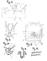
- the figure 1 discloses the schematic diagram, in a particular application, preferred but not limiting, wherein the bistable flexible element 5 and the at least one anti-gallop stop 6 together form a monolithic component.
- the anti-gallop stop 6 comprises two arms 61, 62 whose respective ends 63, 64, may, depending on the position of the rocker 2, interfere with the trajectory of the pin 4, and fill the stop function if the rocker 2 exceeds its normal angular stroke.
- This embodiment with two arms, as shown ensures the limitation of the angle of rotation of the balance 2 in both directions of rotation of the latter.
- the figure 1 shows, in broken line, an interference position with the balance 2, ensuring the limitation of its angular movement.
- the bistable flexible element 5 is here illustrated with these flexible and elastic connecting elements which consist of at least two thin blades 51, 52, each fixed at one end to the structure 7, and connected by a second end to the body of the body. flexible element.
- the bistable flexible element 5 is a bistable flexible pivot.
- the figure 10 schematizes the case where the anti-gallop stop 6 is movable in translation.
- the figure 16 illustrates a more general case where the movement is arbitrary and bistable.
- At least two flexible blades 51, 91, 52, 92 are mounted prestressed in buckling with respect to the structure 7 or with respect to a frame 56 that comprises the bistable flexible element 5.
- Each of the blades 51, 52 can occupy several states, depending on the forces to which it is subjected. Each of these blades is calculated to work in buckling, and can adopt several geometries, according to its buckling mode, as visible on the figure 3 : at rest in 3A, in the first mode of buckling, with a concave or convex shape in 3B, in second mode of buckling with a shape in S or Z in 3C.
- the bistable flexible element 5 may comprise flexible elements with other shapes than these flexible blades 51, 52, illustrated here, without departing from the invention.
- the bistable flexible element 5 may, again, in a particular embodiment, be made in one piece with the structural element 7.
- flexible elements 65, 66 may be included in the arms 61, 62 of the abutment 6 of the anti-gallop mechanism 1, in order to avoid excessive shocks.
- Such a bistable flexible element 5 can be made by silicon technology, "LIGA”, MEMS, or the like. Its inertia is very low compared to that of the pendulum 2, and its actuation weakly disturbs the oscillations of the pendulum 2.
- the figure 2 illustrates a shockproof protection mechanism of the flexible blades 51 and 52 of the bistable flexible element 5. It is useful, even necessary, in cases where the anti-gallop stops 6 must limit the amplitude of the balance 2.
- the purpose is to absorb the shocks in abutment stops 81, 82, which cooperate in abutment abutment with the arms 61, 62, and not to transmit these shocks in the flexible blades 51, 52 to prevent them from breaking.
- the figure 5 has an anti-shock stop 83 coaxial with the flexible pivot.
- the impact stops 81 and 82 comprise substantially cylindrical protrusions which cooperate with grooves of substantially complementary shape on the arms 61 and 62.
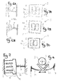
- the flexible bistable pivot 5 can be made according to several principles.
- the figure 3 introduces a bistable state principle studied in this particular case.
- the natural modes of buckling of a stressed beam 9 are used, more particularly the second mode illustrated in 3C.
- a pivot 90 forces the beam 9 to have a node in its middle (center of rotation of the added pivot).
- the center of rotation 50 of the bistable pivot 5 then corresponds to the center of rotation of the pivot 90 added.
- the figure 5 discloses a complete anti-gallop mechanism 1 made according to this principle.
- the flexible bistable pivot 5 comprises at least one prestressed buckling beam 9 according to a second embodiment in which the beam 9 adopts an S or Z shape, a pivot 90 forcing said beam 9 to have a node in the median zone, preferably in its shape. middle.
- the flexible bistable pivot 5 is made by buckling of two prestressed beams 91 and 92 (which together make up the beam 9) by constraining them here via two eccentric screws 94 and 95.
- a third beam 93 fixed to the structure 7 or to a frame 56 of the bistable flexible element 5, force the beam 9 composed of the beams 91 and 92 to deform in the second mode, and plays the role of the pivot 90 of the figure 4 .
- the anti-shock abutment 83 is located in the center of rotation 50 of the flexible bistable pivot 5.
- the figure 11 illustrates an anti-gallop stop 6 comprising at least two levels to maintain the arms 61, 62, of the anti-gallop system in the plane of the balance pin 4: a first upper level with arms 61 and 62 cooperating with this ankle 4, and a second lower level with a stinger 67 cooperating with a notch 21 of the balance 3.
- the anti-gallop mechanism 1 may also advantageously comprise means for creating a force or a repulsion couple between the rocker 2 and the arms 61, 62, of the anti-gallop mechanism 1.
- the figure 14 illustrates the case where this repulsion function is fulfilled by magnets located in a vertical orientation, at the level of the pin 4 and ends 63, 64, arms 61, 62.
- the figure 15 illustrates a similar embodiment, with an orientation in the plane of the magnetic field, we see the north and south poles of these magnets.
- electrons electrostatic charges
- magnets electrostatic charges
- the mechanism works in a similar way to the horns of a Swiss anchor, there is a release then an impulse.
- the rocker 2, or / and at least the arms 61, 62, of the anti-gallop stop 6, or even the anti-gallop mechanism 1 complete when it is monoblock in an advantageous embodiment, is realized in technology silicon from a silicon wafer, with or without growth of silicon oxide, and with a surface layer containing, as the case may be, or magnets or magnetic particles on the one hand, or electrets on the other hand go.
- this particular layer can be produced by a galvanic method, or by sputtering, or by another suitable microtechnical structuring method.
- the creation of stresses in the blades constituting the beams 91 and 92 can be done by oxidation of the silicon.
- the silicon oxide takes a larger volume during its growth to from silicon, as visible on the figure 6 , where pockets 54, 55, of SiO2, are created in a frame 56 made of silicon.
- this frame 56 can also constitute the structure 7, or can be connected very simply by any conventional mechanical fastening technology.
- FIGS. 6A and 6B illustrate, before and after oxidation of silicon, a detail of an area with strong differences in section, and strongly modified after formation of silicon dioxide, and subjecting to a buckling force a straight beam P of smaller section than a head T of which it constitutes an extension.
- FIG. 7 illustrates another principle of prestressing by buckling resistance differential between a parallel oxidized silicon beam system and a single beam thus prestressing in buckling, and has a simple mechanism where, in the left part, a parallel structure 94 comprises a bundle of beams parallel 95 which will, after oxidation (in broken line), constrain in bending buckling, in the right part, a flexible element to constrain 96, in this case a beam 9, 91, 92, or the like, which is desired to obtain a deformation, the buckling resistance of the parallel structure 94 being much greater than that of the flexible element to constrain 96.
- FIGS. 7A, 7B, 7C illustrate successive steps of a method of oxidation and buckling of a beam P, formed between two windows F1, F2 of a frame C.
- Figure 7A shows the basic structure resulting from the etching of the silicon, when it is put in an oven.
- the Figure 7B illustrates the development of silicon oxide SiO 2 , inside windows F1 and F2 and thus on the flanks of the beam P, by maintaining the structure at 1100 ° C. for several hours; in known manner, the growth of silicon dioxide SiO 2 is by partial consumption of silicon towards the outside of the component, and therefore in the thin beam P the proportion of silicon dioxide SiO 2 increases when the proportion of silicon decreases over time during this treatment at 1100 ° C.
- the Figure 7C shows the contraction of the structure after cooling to room temperature, about 20 ° C: the lateral uprights M1, M2 of the frame C, parallel to the beam P, which are essentially formed of silicon and a little silicon dioxide , contract more than the beam P, which is then essentially formed of silicon dioxide which has a coefficient of expansion lower than the silicon.
- the beam P is subjected to a buckling force, and takes a bistable state.
- FIG. 12 Another variant is illustrated in the figure 12 .
- the Figures 17A and 17B also illustrate the obtaining of prestressing by meeting the growths of oxide in a coil.
- the Figures 18A and 18B (and their details in Figures 19A and 19B ) show the obtaining of the prestressing by the opening of the angles at the top of a zig-zag profile according to the same principle: the growth of the silicon oxide forces the opening of these angles, and the displacement is amplified by the Z or zig-zag geometry of the structure.
- the Figures 20A and 20B show a variation of angle obtained by the variation of the radius of curvature of the oxidized walls in a zone with a very small radius of curvature.
- the invention also relates to a method by which a bistable flexible blade is produced.
- the structure of the anti-gallop mechanism 1 is made of monocrystalline quartz.
- the central monocrystalline quartz core is coated on its upper and lower faces with a deposit made at a temperature above room temperature, with a coefficient ⁇ smaller than the coefficient ⁇ x, y of quartz. This ⁇ x, y coefficient of quartz is 7.5 ppm / ° C.
- the anti-gallop mechanism 1 illustrated here limits the direction of rotation of the balance in both directions of rotation. It only slightly disturbs the oscillations of the pendulum 2.
- the invention can be used in mechanical watches that do not have an anti-gallop mechanism.
- this horological limiting or transmission mechanism 1000 is an anchor mechanism 3000 for an escape mechanism, in particular but not limited to a Swiss anchor, on the same principle, for its cooperation with a beam 2 and with a escape wheel 5000.
- Such an anchor 3000 comprises at least one flexible element 5 multistable, including bistable. It can be realized according to a flexible anchor execution with constant force according to the request EP12183559.9 the same depositor.
- this anchor 3000 is performed by horns 3001 similar to the ends 63, 64, arms 61 and 62 of the anti-gallop stop 6 described above, these horns 3001, carried by a first part 3100 anchor 3000, are connected by at least one flexible sheet 5 multistable, in particular bistable, either to a fixed structure 7, or preferably to a second part 3200 of the anchor comprising pallets 3002 for cooperation with the teeth 5001 of the escape wheel 5000.
- these pallets 3002 are advantageously constructed analogously to these arms 61 and 62, and are connected by at least one flexible multi-stable blade 5, in particular bistable, or to a fixed structure 7, preferably in the first part 3100 of the anchor comprising the horns 3001.
- the interaction between the horns 3001 and the balance 2 on the one hand, or / and between the pallets 3002 and the escape wheel 5000 on the other hand is achieved without contact or with an attenuated contact, and, for this purpose, the relevant surfaces of the horns 3001 and / or the pallets 3002 are magnetized or electrified to cooperate in repulsion with antagonistic surfaces of the balance or / and respectively of the escape wheel , which are of suitable material, and / or advantageously magnetized or respectively electrified in a complementary manner.
- the invention also relates to a clockwork movement comprising at least one balance regulating member 2, and which comprises at least one watchmaking clock or transmission mechanism 1000 according to the invention.
- the movement 10 comprises a structure 7 to which is fixed a bistable flexible element 5 of this clock-limiting mechanism or transmission 1000, or this bistable flexible element 5 itself constitutes such a structure.
- the invention also relates to a timepiece 100, in particular a watch, comprising at least one such movement 10 or at least one such horological limiting or transmission mechanism 1000.
- the technologies used for producing the device are not limited to silicon technology but also to "LIGA”, MEMS and other micro-manufacturing processes.
Landscapes
- Chemical & Material Sciences (AREA)
- General Physics & Mathematics (AREA)
- Physics & Mathematics (AREA)
- Organic Chemistry (AREA)
- Engineering & Computer Science (AREA)
- Crystallography & Structural Chemistry (AREA)
- Materials Engineering (AREA)
- Metallurgy (AREA)
- Chemical Kinetics & Catalysis (AREA)
- Inorganic Chemistry (AREA)
- Micromachines (AREA)
- Pressure Sensors (AREA)
- Laminated Bodies (AREA)
- Electromechanical Clocks (AREA)
Priority Applications (25)
| Application Number | Priority Date | Filing Date | Title |
|---|---|---|---|
| EP12192026.8A EP2730980B1 (de) | 2012-11-09 | 2012-11-09 | Uhrmechanismus zur Begrenzung oder Übertragung |
| CH02305/12A CH707171A2 (fr) | 2012-11-09 | 2012-11-09 | Mécanisme horloger de limitation ou transmission. |
| US14/071,961 US9317015B2 (en) | 2012-11-09 | 2013-11-05 | Timepiece anti-trip mechanism |
| TW102140096A TWI612398B (zh) | 2012-11-09 | 2013-11-05 | 計時器限制器與使用其之計時器機芯及計時器 |
| KR1020157006271A KR101710288B1 (ko) | 2012-11-09 | 2013-11-06 | 타임피스 이스케이프먼트용 팰릿 메카니즘 |
| JP2015533642A JP5960920B2 (ja) | 2012-11-09 | 2013-11-06 | 計時器用エスケープのためのパレットレバー機構 |
| JP2015532476A JP5925388B2 (ja) | 2012-11-09 | 2013-11-06 | 可撓性多重安定要素を作る方法 |
| PCT/EP2013/073116 WO2014072317A2 (fr) | 2012-11-09 | 2013-11-06 | Procédé de réalisation d'un élément flexible multistable |
| EP13789254.3A EP2917788B1 (de) | 2012-11-09 | 2013-11-06 | Verfahren zur herstellung eines multistabilen flexiblen elements |
| PCT/EP2013/073118 WO2014072319A1 (fr) | 2012-11-09 | 2013-11-06 | Mécanisme à ancre pour échappement d'horlogerie |
| RU2015121974/12A RU2605502C1 (ru) | 2012-11-09 | 2013-11-06 | Способ создания гибкого мультистабильного элемента |
| US14/423,900 US9778620B2 (en) | 2012-11-09 | 2013-11-06 | Method for creating a flexible, multistable element |
| RU2015121916/12A RU2603954C1 (ru) | 2012-11-09 | 2013-11-06 | Анкерное устройство для часового спуска |
| KR1020157003967A KR101694644B1 (ko) | 2012-11-09 | 2013-11-06 | 가요성 다안정 요소의 제조 방법 |
| CN201380058479.8A CN104769510B (zh) | 2012-11-09 | 2013-11-06 | 用于形成柔性多稳态元件的方法 |
| US14/423,918 US9310771B2 (en) | 2012-11-09 | 2013-11-06 | Pallet lever mechanism for timepiece escapement |
| CN201380052681.XA CN104737080B (zh) | 2012-11-09 | 2013-11-06 | 用于钟表擒纵机构的擒纵叉机构 |
| EP13789255.0A EP2917789B1 (de) | 2012-11-09 | 2013-11-06 | Palettenmechanismus für eine uhrenhemmung |
| KR1020130135749A KR101505325B1 (ko) | 2012-11-09 | 2013-11-08 | 타임피스 안티 트립 메카니즘 |
| RU2013150114A RU2629546C2 (ru) | 2012-11-09 | 2013-11-08 | Препятствующий отсоединению механизм часов |
| CN201310726119.2A CN103809421B (zh) | 2012-11-09 | 2013-11-08 | 钟表的防脱扣机构 |
| JP2013231838A JP5726988B2 (ja) | 2012-11-09 | 2013-11-08 | 時計のトリップ防止機構、時計ムーブメント、時計および腕時計 |
| HK14111644.1A HK1198214A1 (en) | 2012-11-09 | 2014-11-18 | Timepiece anti-trip mechanism |
| HK15112384.2A HK1211712A1 (en) | 2012-11-09 | 2015-12-16 | Pallet mechanism for a timepiece escapement |
| HK15112786.6A HK1212046A1 (en) | 2012-11-09 | 2015-12-29 | Method for the production of a multistable flexible element |
Applications Claiming Priority (1)
| Application Number | Priority Date | Filing Date | Title |
|---|---|---|---|
| EP12192026.8A EP2730980B1 (de) | 2012-11-09 | 2012-11-09 | Uhrmechanismus zur Begrenzung oder Übertragung |
Publications (2)
| Publication Number | Publication Date |
|---|---|
| EP2730980A1 true EP2730980A1 (de) | 2014-05-14 |
| EP2730980B1 EP2730980B1 (de) | 2018-08-29 |
Family
ID=47143753
Family Applications (3)
| Application Number | Title | Priority Date | Filing Date |
|---|---|---|---|
| EP12192026.8A Active EP2730980B1 (de) | 2012-11-09 | 2012-11-09 | Uhrmechanismus zur Begrenzung oder Übertragung |
| EP13789255.0A Active EP2917789B1 (de) | 2012-11-09 | 2013-11-06 | Palettenmechanismus für eine uhrenhemmung |
| EP13789254.3A Active EP2917788B1 (de) | 2012-11-09 | 2013-11-06 | Verfahren zur herstellung eines multistabilen flexiblen elements |
Family Applications After (2)
| Application Number | Title | Priority Date | Filing Date |
|---|---|---|---|
| EP13789255.0A Active EP2917789B1 (de) | 2012-11-09 | 2013-11-06 | Palettenmechanismus für eine uhrenhemmung |
| EP13789254.3A Active EP2917788B1 (de) | 2012-11-09 | 2013-11-06 | Verfahren zur herstellung eines multistabilen flexiblen elements |
Country Status (10)
| Country | Link |
|---|---|
| US (3) | US9317015B2 (de) |
| EP (3) | EP2730980B1 (de) |
| JP (3) | JP5960920B2 (de) |
| KR (3) | KR101694644B1 (de) |
| CN (3) | CN104769510B (de) |
| CH (1) | CH707171A2 (de) |
| HK (3) | HK1198214A1 (de) |
| RU (3) | RU2603954C1 (de) |
| TW (1) | TWI612398B (de) |
| WO (2) | WO2014072319A1 (de) |
Cited By (1)
| Publication number | Priority date | Publication date | Assignee | Title |
|---|---|---|---|---|
| WO2017032528A1 (fr) * | 2015-08-21 | 2017-03-02 | Patek Philippe Sa Geneve | Dispositif mécanique bistable, notamment pour l'horlogerie |
Families Citing this family (17)
| Publication number | Priority date | Publication date | Assignee | Title |
|---|---|---|---|---|
| EP2781965B1 (de) * | 2013-03-19 | 2017-11-15 | Nivarox-FAR S.A. | Kassette für Uhrwerksmechanismus |
| EP2799937B1 (de) * | 2013-05-01 | 2020-09-16 | Rolex Sa | Dämpfungskörper eines Unruh-Oszillators einer Uhr |
| EP3032352A1 (de) * | 2014-12-09 | 2016-06-15 | LVMH Swiss Manufactures SA | Uhrregler, Uhrwerk und Uhr mit solch einem Regler |
| CH710692B1 (fr) * | 2015-02-03 | 2021-09-15 | Eta Sa Mft Horlogere Suisse | Mécanisme oscillateur d'horlogerie. |
| EP3176650B1 (de) * | 2015-12-02 | 2019-02-06 | Nivarox-FAR S.A. | Schutz einer uhrkomponente aus mikro-bearbeitbarem material |
| EP3185083B1 (de) * | 2015-12-23 | 2018-11-14 | Montres Breguet S.A. | Mechanischer uhrmechanismus mit einer ankerhemmung |
| FR3048791B1 (fr) * | 2016-03-14 | 2018-05-18 | Lvmh Swiss Manufactures Sa | Mecanisme pour piece d'horlogerie et piece d'horlogerie comprenant un tel mecanisme |
| EP3312682B1 (de) * | 2016-10-18 | 2019-02-20 | ETA SA Manufacture Horlogère Suisse | Qualitativ hochwertiger resonator für mechanische armbanduhr |
| CH713288A1 (fr) * | 2016-12-23 | 2018-06-29 | Sa De La Manufacture Dhorlogerie Audemars Piguet & Cie | Composant monolithique flexible pour pièce d'horlogerie. |
| JP7100650B2 (ja) | 2017-02-13 | 2022-07-13 | パテック フィリップ ソシエテ アノニム ジュネーブ | 時計用駆動部材 |
| EP3425458A1 (de) * | 2017-07-07 | 2019-01-09 | ETA SA Manufacture Horlogère Suisse | Abtrennbares stück eines uhrenoszillators |
| EP3451072B1 (de) * | 2017-08-29 | 2023-10-25 | The Swatch Group Research and Development Ltd | Isochrones drehgelenk für uhrresonator |
| EP3525046A1 (de) * | 2018-02-12 | 2019-08-14 | The Swatch Group Research and Development Ltd | Uhrwerkoszillator, der für winkelbeschleunigungen des tragens unempfindlich ist |
| EP3557334A1 (de) * | 2018-04-17 | 2019-10-23 | Dominique Renaud SA | Uhrhemmungsmechanismus mit ruheanker, und uhr, die mit einem solchen hemmungsmechanismus ausgestattet ist |
| EP3561603B1 (de) * | 2018-04-25 | 2021-01-06 | The Swatch Group Research and Development Ltd | Reguliermechanismus einer uhr mit verbundenen resonatoren |
| EP3812843A1 (de) * | 2019-10-25 | 2021-04-28 | ETA SA Manufacture Horlogère Suisse | Flexible führung und gesamtheit von übereinander angeordneten flexiblen führungen für sich drehenden resonatormechanismus, insbesondere für uhrwerk |
| EP3865954A1 (de) * | 2020-02-12 | 2021-08-18 | Nivarox-FAR S.A. | Herstellungsverfahren einer monoblock-vorrichtung mit federzungen aus silizium, für uhrwerk |
Citations (11)
| Publication number | Priority date | Publication date | Assignee | Title |
|---|---|---|---|---|
| FR2258656A1 (de) * | 1974-01-18 | 1975-08-18 | Far Fab Assortiments Reunies | |
| EP1710636A1 (de) * | 2005-04-06 | 2006-10-11 | Daniel Rochat | Hemmung für eine Uhr |
| WO2007000271A1 (fr) * | 2005-06-28 | 2007-01-04 | Eta Sa Manufacture Horlogere Suisse | Piece de micro-mecanique renforcee |
| EP2037335A2 (de) * | 2007-09-13 | 2009-03-18 | August Enzler | Anker für eine Uhrenhemmung |
| WO2011120180A1 (fr) * | 2010-04-01 | 2011-10-06 | Rolex S.A. | Dispositif de blocage pour roue dentée |
| CH703333A2 (fr) * | 2010-06-22 | 2011-12-30 | Bruno Fragniere | Ancre d'échappement. |
| EP2407831A1 (de) * | 2010-07-12 | 2012-01-18 | Rolex Sa | Spirale für Unruh-Oszillator einer Uhr, und ihr Herstellungsverfahren |
| EP2431823A1 (de) * | 2010-09-16 | 2012-03-21 | Blancpain S.A. | Blancpain-Hemmung mit verbessertem Anker für Uhrwerk |
| EP2450757A1 (de) * | 2010-11-04 | 2012-05-09 | Nivarox-FAR S.A. | Antischwingungsvorrichtung für Uhrenhemmungsmechanismus |
| EP2450756A1 (de) * | 2010-11-04 | 2012-05-09 | Nivarox-FAR S.A. | Antischwingungsvorrichtung für Uhrenhemmungsmechanismus |
| WO2013144236A1 (fr) * | 2012-03-29 | 2013-10-03 | Nivarox-Far S.A. | Mécanisme d'échappement flexible à cadre mobile |
Family Cites Families (15)
| Publication number | Priority date | Publication date | Assignee | Title |
|---|---|---|---|---|
| US3183426A (en) * | 1962-02-14 | 1965-05-11 | Cons Electronics Ind | Magnetically coupled constant speed system |
| DE60035765T2 (de) * | 2000-02-07 | 2008-04-30 | Audemars Piguet (Renaud Et Papi) S.A. | Verriegelungsvorrichtung für ein Zeitmessgerät |
| FR2865724A1 (fr) | 2004-02-04 | 2005-08-05 | St Microelectronics Sa | Microsysteme electromecanique pouvant basculer entre deux positions stables |
| EP1666990B1 (de) | 2004-10-05 | 2011-12-28 | Montres Breguet S.A. | Vorrichtung zum Galoppschutz für Uhrenhemmung |
| EP1708047B1 (de) * | 2005-03-30 | 2008-03-26 | Montres Breguet S.A. | Chronometerhemmung für Uhren |
| EP1770452A1 (de) * | 2005-09-30 | 2007-04-04 | Peter Baumberger | Chronometerhemmung für Uhren |
| ATE388428T1 (de) | 2005-12-20 | 2008-03-15 | Montres Breguet Sa | Vorrichtung zum galoppschutz für uhrenhemmung |
| EP1998236B1 (de) * | 2007-05-30 | 2010-07-28 | Omega SA | Ankerhemmung für Uhren |
| EP2105806B1 (de) * | 2008-03-27 | 2013-11-13 | Sowind S.A. | Hemmungsmechanismus |
| EP2199875B1 (de) * | 2008-12-16 | 2014-09-24 | Rolex Sa | Chronometerhemmung |
| JP5462006B2 (ja) * | 2009-02-17 | 2014-04-02 | セイコーインスツル株式会社 | 脱進調速機、機械式時計、及びアンクル体の製造方法 |
| CH701499B1 (fr) * | 2009-07-23 | 2016-09-15 | Montres Breguet Sa | Procède de fabrication d'une pièce micromécanique en silicium renforcé. |
| CH702930A2 (fr) * | 2010-04-01 | 2011-10-14 | Patek Philippe Sa Geneve | Echappement d'horlogerie à protection contre les chocs. |
| EP2450755B1 (de) * | 2010-11-04 | 2015-01-21 | Nivarox-FAR S.A. | Synchronhemmung für Uhrwerk |
| JP5794613B2 (ja) * | 2011-03-11 | 2015-10-14 | セイコーインスツル株式会社 | 時計用デテント脱進機、及び機械式時計 |
-
2012
- 2012-11-09 CH CH02305/12A patent/CH707171A2/fr not_active Application Discontinuation
- 2012-11-09 EP EP12192026.8A patent/EP2730980B1/de active Active
-
2013
- 2013-11-05 TW TW102140096A patent/TWI612398B/zh active
- 2013-11-05 US US14/071,961 patent/US9317015B2/en active Active
- 2013-11-06 RU RU2015121916/12A patent/RU2603954C1/ru active
- 2013-11-06 EP EP13789255.0A patent/EP2917789B1/de active Active
- 2013-11-06 US US14/423,900 patent/US9778620B2/en active Active
- 2013-11-06 CN CN201380058479.8A patent/CN104769510B/zh active Active
- 2013-11-06 JP JP2015533642A patent/JP5960920B2/ja active Active
- 2013-11-06 WO PCT/EP2013/073118 patent/WO2014072319A1/fr active Application Filing
- 2013-11-06 EP EP13789254.3A patent/EP2917788B1/de active Active
- 2013-11-06 US US14/423,918 patent/US9310771B2/en active Active
- 2013-11-06 CN CN201380052681.XA patent/CN104737080B/zh active Active
- 2013-11-06 WO PCT/EP2013/073116 patent/WO2014072317A2/fr active Application Filing
- 2013-11-06 KR KR1020157003967A patent/KR101694644B1/ko active IP Right Grant
- 2013-11-06 KR KR1020157006271A patent/KR101710288B1/ko active IP Right Grant
- 2013-11-06 RU RU2015121974/12A patent/RU2605502C1/ru active
- 2013-11-06 JP JP2015532476A patent/JP5925388B2/ja active Active
- 2013-11-08 JP JP2013231838A patent/JP5726988B2/ja active Active
- 2013-11-08 CN CN201310726119.2A patent/CN103809421B/zh active Active
- 2013-11-08 RU RU2013150114A patent/RU2629546C2/ru active
- 2013-11-08 KR KR1020130135749A patent/KR101505325B1/ko active IP Right Grant
-
2014
- 2014-11-18 HK HK14111644.1A patent/HK1198214A1/xx unknown
-
2015
- 2015-12-16 HK HK15112384.2A patent/HK1211712A1/xx unknown
- 2015-12-29 HK HK15112786.6A patent/HK1212046A1/xx unknown
Patent Citations (11)
| Publication number | Priority date | Publication date | Assignee | Title |
|---|---|---|---|---|
| FR2258656A1 (de) * | 1974-01-18 | 1975-08-18 | Far Fab Assortiments Reunies | |
| EP1710636A1 (de) * | 2005-04-06 | 2006-10-11 | Daniel Rochat | Hemmung für eine Uhr |
| WO2007000271A1 (fr) * | 2005-06-28 | 2007-01-04 | Eta Sa Manufacture Horlogere Suisse | Piece de micro-mecanique renforcee |
| EP2037335A2 (de) * | 2007-09-13 | 2009-03-18 | August Enzler | Anker für eine Uhrenhemmung |
| WO2011120180A1 (fr) * | 2010-04-01 | 2011-10-06 | Rolex S.A. | Dispositif de blocage pour roue dentée |
| CH703333A2 (fr) * | 2010-06-22 | 2011-12-30 | Bruno Fragniere | Ancre d'échappement. |
| EP2407831A1 (de) * | 2010-07-12 | 2012-01-18 | Rolex Sa | Spirale für Unruh-Oszillator einer Uhr, und ihr Herstellungsverfahren |
| EP2431823A1 (de) * | 2010-09-16 | 2012-03-21 | Blancpain S.A. | Blancpain-Hemmung mit verbessertem Anker für Uhrwerk |
| EP2450757A1 (de) * | 2010-11-04 | 2012-05-09 | Nivarox-FAR S.A. | Antischwingungsvorrichtung für Uhrenhemmungsmechanismus |
| EP2450756A1 (de) * | 2010-11-04 | 2012-05-09 | Nivarox-FAR S.A. | Antischwingungsvorrichtung für Uhrenhemmungsmechanismus |
| WO2013144236A1 (fr) * | 2012-03-29 | 2013-10-03 | Nivarox-Far S.A. | Mécanisme d'échappement flexible à cadre mobile |
Cited By (2)
| Publication number | Priority date | Publication date | Assignee | Title |
|---|---|---|---|---|
| WO2017032528A1 (fr) * | 2015-08-21 | 2017-03-02 | Patek Philippe Sa Geneve | Dispositif mécanique bistable, notamment pour l'horlogerie |
| EP3338144B1 (de) * | 2015-08-21 | 2019-09-25 | Patek Philippe SA Genève | Bistabile mechanische vorrichtung für uhrwerke |
Also Published As
Similar Documents
| Publication | Publication Date | Title |
|---|---|---|
| EP2917789B1 (de) | Palettenmechanismus für eine uhrenhemmung | |
| EP3545365B1 (de) | Sich drehender resonator mit einer flexiblen führung, der von einer freien ankerhemmung gehalten wird | |
| EP2706416B1 (de) | Flexibler Anker mit konstanter Kraft | |
| EP3182213B1 (de) | Einstellmechanismus der mittleren geschwindigkeit in einem uhrwerk, und entsprechendes uhrwerk | |
| EP3040783B1 (de) | Untereinheit für einen mechanismus zur einstellung der geschwindigkeit in einem uhrwerk, und ein solcher mechanismus | |
| EP2690507A1 (de) | Spiralfeder einer Uhr | |
| CH713787A2 (fr) | Dispositif horloger à organe de positionnement. | |
| CH714361A2 (fr) | Résonateur rotatif à guidage flexible entretenu par un échappement libre à ancre. | |
| WO2017102917A1 (fr) | Oscillateur mécanique pour pièce d'horlogerie, mécanisme de réglage comportant cet oscillateur mécanique, et mouvement d'horlogerie | |
| EP3619579B1 (de) | Uhrvorrichtung mit positionierorgan | |
| EP3451073B1 (de) | Uhrwerkoszillator mit flexiblen führungen mit grosser winkelförmiger laufbahn | |
| EP3761122B1 (de) | Drehteil für uhrhemmung, entsprechender hemmungsmechanismus und entsprechendes uhrenteil | |
| EP3479175B1 (de) | Mechanisches uhrwerk | |
| EP3707564A1 (de) | Uhr mit uhrenkomponente und vorrichtung zum translatorischen führen eines beweglichen elements | |
| EP3435171A2 (de) | Uhrwerkoszillator mit flexiblen führungen mit grosser winkelförmiger laufbahn |
Legal Events
| Date | Code | Title | Description |
|---|---|---|---|
| PUAI | Public reference made under article 153(3) epc to a published international application that has entered the european phase |
Free format text: ORIGINAL CODE: 0009012 |
|
| 17P | Request for examination filed |
Effective date: 20121109 |
|
| AK | Designated contracting states |
Kind code of ref document: A1 Designated state(s): AL AT BE BG CH CY CZ DE DK EE ES FI FR GB GR HR HU IE IS IT LI LT LU LV MC MK MT NL NO PL PT RO RS SE SI SK SM TR |
|
| AX | Request for extension of the european patent |
Extension state: BA ME |
|
| R17P | Request for examination filed (corrected) |
Effective date: 20141114 |
|
| RBV | Designated contracting states (corrected) |
Designated state(s): AL AT BE BG CH CY CZ DE DK EE ES FI FR GB GR HR HU IE IS IT LI LT LU LV MC MK MT NL NO PL PT RO RS SE SI SK SM TR |
|
| 17Q | First examination report despatched |
Effective date: 20170323 |
|
| GRAP | Despatch of communication of intention to grant a patent |
Free format text: ORIGINAL CODE: EPIDOSNIGR1 |
|
| INTG | Intention to grant announced |
Effective date: 20180511 |
|
| GRAS | Grant fee paid |
Free format text: ORIGINAL CODE: EPIDOSNIGR3 |
|
| GRAA | (expected) grant |
Free format text: ORIGINAL CODE: 0009210 |
|
| AK | Designated contracting states |
Kind code of ref document: B1 Designated state(s): AL AT BE BG CH CY CZ DE DK EE ES FI FR GB GR HR HU IE IS IT LI LT LU LV MC MK MT NL NO PL PT RO RS SE SI SK SM TR |
|
| REG | Reference to a national code |
Ref country code: GB Ref legal event code: FG4D Free format text: NOT ENGLISH |
|
| REG | Reference to a national code |
Ref country code: CH Ref legal event code: EP |
|
| REG | Reference to a national code |
Ref country code: AT Ref legal event code: REF Ref document number: 1035842 Country of ref document: AT Kind code of ref document: T Effective date: 20180915 |
|
| REG | Reference to a national code |
Ref country code: IE Ref legal event code: FG4D Free format text: LANGUAGE OF EP DOCUMENT: FRENCH |
|
| REG | Reference to a national code |
Ref country code: DE Ref legal event code: R096 Ref document number: 602012050327 Country of ref document: DE |
|
| REG | Reference to a national code |
Ref country code: FR Ref legal event code: PLFP Year of fee payment: 7 |
|
| REG | Reference to a national code |
Ref country code: NL Ref legal event code: MP Effective date: 20180829 |
|
| REG | Reference to a national code |
Ref country code: LT Ref legal event code: MG4D |
|
| PG25 | Lapsed in a contracting state [announced via postgrant information from national office to epo] |
Ref country code: FI Free format text: LAPSE BECAUSE OF FAILURE TO SUBMIT A TRANSLATION OF THE DESCRIPTION OR TO PAY THE FEE WITHIN THE PRESCRIBED TIME-LIMIT Effective date: 20180829 Ref country code: BG Free format text: LAPSE BECAUSE OF FAILURE TO SUBMIT A TRANSLATION OF THE DESCRIPTION OR TO PAY THE FEE WITHIN THE PRESCRIBED TIME-LIMIT Effective date: 20181129 Ref country code: NL Free format text: LAPSE BECAUSE OF FAILURE TO SUBMIT A TRANSLATION OF THE DESCRIPTION OR TO PAY THE FEE WITHIN THE PRESCRIBED TIME-LIMIT Effective date: 20180829 Ref country code: LT Free format text: LAPSE BECAUSE OF FAILURE TO SUBMIT A TRANSLATION OF THE DESCRIPTION OR TO PAY THE FEE WITHIN THE PRESCRIBED TIME-LIMIT Effective date: 20180829 Ref country code: GR Free format text: LAPSE BECAUSE OF FAILURE TO SUBMIT A TRANSLATION OF THE DESCRIPTION OR TO PAY THE FEE WITHIN THE PRESCRIBED TIME-LIMIT Effective date: 20181130 Ref country code: NO Free format text: LAPSE BECAUSE OF FAILURE TO SUBMIT A TRANSLATION OF THE DESCRIPTION OR TO PAY THE FEE WITHIN THE PRESCRIBED TIME-LIMIT Effective date: 20181129 Ref country code: SE Free format text: LAPSE BECAUSE OF FAILURE TO SUBMIT A TRANSLATION OF THE DESCRIPTION OR TO PAY THE FEE WITHIN THE PRESCRIBED TIME-LIMIT Effective date: 20180829 Ref country code: IS Free format text: LAPSE BECAUSE OF FAILURE TO SUBMIT A TRANSLATION OF THE DESCRIPTION OR TO PAY THE FEE WITHIN THE PRESCRIBED TIME-LIMIT Effective date: 20181229 Ref country code: RS Free format text: LAPSE BECAUSE OF FAILURE TO SUBMIT A TRANSLATION OF THE DESCRIPTION OR TO PAY THE FEE WITHIN THE PRESCRIBED TIME-LIMIT Effective date: 20180829 |
|
| REG | Reference to a national code |
Ref country code: AT Ref legal event code: MK05 Ref document number: 1035842 Country of ref document: AT Kind code of ref document: T Effective date: 20180829 |
|
| PG25 | Lapsed in a contracting state [announced via postgrant information from national office to epo] |
Ref country code: AL Free format text: LAPSE BECAUSE OF FAILURE TO SUBMIT A TRANSLATION OF THE DESCRIPTION OR TO PAY THE FEE WITHIN THE PRESCRIBED TIME-LIMIT Effective date: 20180829 Ref country code: HR Free format text: LAPSE BECAUSE OF FAILURE TO SUBMIT A TRANSLATION OF THE DESCRIPTION OR TO PAY THE FEE WITHIN THE PRESCRIBED TIME-LIMIT Effective date: 20180829 Ref country code: LV Free format text: LAPSE BECAUSE OF FAILURE TO SUBMIT A TRANSLATION OF THE DESCRIPTION OR TO PAY THE FEE WITHIN THE PRESCRIBED TIME-LIMIT Effective date: 20180829 |
|
| PG25 | Lapsed in a contracting state [announced via postgrant information from national office to epo] |
Ref country code: IT Free format text: LAPSE BECAUSE OF FAILURE TO SUBMIT A TRANSLATION OF THE DESCRIPTION OR TO PAY THE FEE WITHIN THE PRESCRIBED TIME-LIMIT Effective date: 20180829 Ref country code: AT Free format text: LAPSE BECAUSE OF FAILURE TO SUBMIT A TRANSLATION OF THE DESCRIPTION OR TO PAY THE FEE WITHIN THE PRESCRIBED TIME-LIMIT Effective date: 20180829 Ref country code: EE Free format text: LAPSE BECAUSE OF FAILURE TO SUBMIT A TRANSLATION OF THE DESCRIPTION OR TO PAY THE FEE WITHIN THE PRESCRIBED TIME-LIMIT Effective date: 20180829 Ref country code: PL Free format text: LAPSE BECAUSE OF FAILURE TO SUBMIT A TRANSLATION OF THE DESCRIPTION OR TO PAY THE FEE WITHIN THE PRESCRIBED TIME-LIMIT Effective date: 20180829 Ref country code: RO Free format text: LAPSE BECAUSE OF FAILURE TO SUBMIT A TRANSLATION OF THE DESCRIPTION OR TO PAY THE FEE WITHIN THE PRESCRIBED TIME-LIMIT Effective date: 20180829 Ref country code: CZ Free format text: LAPSE BECAUSE OF FAILURE TO SUBMIT A TRANSLATION OF THE DESCRIPTION OR TO PAY THE FEE WITHIN THE PRESCRIBED TIME-LIMIT Effective date: 20180829 Ref country code: ES Free format text: LAPSE BECAUSE OF FAILURE TO SUBMIT A TRANSLATION OF THE DESCRIPTION OR TO PAY THE FEE WITHIN THE PRESCRIBED TIME-LIMIT Effective date: 20180829 |
|
| PG25 | Lapsed in a contracting state [announced via postgrant information from national office to epo] |
Ref country code: SK Free format text: LAPSE BECAUSE OF FAILURE TO SUBMIT A TRANSLATION OF THE DESCRIPTION OR TO PAY THE FEE WITHIN THE PRESCRIBED TIME-LIMIT Effective date: 20180829 Ref country code: SM Free format text: LAPSE BECAUSE OF FAILURE TO SUBMIT A TRANSLATION OF THE DESCRIPTION OR TO PAY THE FEE WITHIN THE PRESCRIBED TIME-LIMIT Effective date: 20180829 Ref country code: DK Free format text: LAPSE BECAUSE OF FAILURE TO SUBMIT A TRANSLATION OF THE DESCRIPTION OR TO PAY THE FEE WITHIN THE PRESCRIBED TIME-LIMIT Effective date: 20180829 |
|
| REG | Reference to a national code |
Ref country code: DE Ref legal event code: R097 Ref document number: 602012050327 Country of ref document: DE |
|
| PLBE | No opposition filed within time limit |
Free format text: ORIGINAL CODE: 0009261 |
|
| STAA | Information on the status of an ep patent application or granted ep patent |
Free format text: STATUS: NO OPPOSITION FILED WITHIN TIME LIMIT |
|
| PG25 | Lapsed in a contracting state [announced via postgrant information from national office to epo] |
Ref country code: MC Free format text: LAPSE BECAUSE OF FAILURE TO SUBMIT A TRANSLATION OF THE DESCRIPTION OR TO PAY THE FEE WITHIN THE PRESCRIBED TIME-LIMIT Effective date: 20180829 Ref country code: LU Free format text: LAPSE BECAUSE OF NON-PAYMENT OF DUE FEES Effective date: 20181109 |
|
| 26N | No opposition filed |
Effective date: 20190531 |
|
| REG | Reference to a national code |
Ref country code: BE Ref legal event code: MM Effective date: 20181130 |
|
| REG | Reference to a national code |
Ref country code: IE Ref legal event code: MM4A |
|
| PG25 | Lapsed in a contracting state [announced via postgrant information from national office to epo] |
Ref country code: SI Free format text: LAPSE BECAUSE OF FAILURE TO SUBMIT A TRANSLATION OF THE DESCRIPTION OR TO PAY THE FEE WITHIN THE PRESCRIBED TIME-LIMIT Effective date: 20180829 |
|
| PG25 | Lapsed in a contracting state [announced via postgrant information from national office to epo] |
Ref country code: IE Free format text: LAPSE BECAUSE OF NON-PAYMENT OF DUE FEES Effective date: 20181109 |
|
| PG25 | Lapsed in a contracting state [announced via postgrant information from national office to epo] |
Ref country code: BE Free format text: LAPSE BECAUSE OF NON-PAYMENT OF DUE FEES Effective date: 20181130 |
|
| PG25 | Lapsed in a contracting state [announced via postgrant information from national office to epo] |
Ref country code: MT Free format text: LAPSE BECAUSE OF FAILURE TO SUBMIT A TRANSLATION OF THE DESCRIPTION OR TO PAY THE FEE WITHIN THE PRESCRIBED TIME-LIMIT Effective date: 20180829 |
|
| PG25 | Lapsed in a contracting state [announced via postgrant information from national office to epo] |
Ref country code: TR Free format text: LAPSE BECAUSE OF FAILURE TO SUBMIT A TRANSLATION OF THE DESCRIPTION OR TO PAY THE FEE WITHIN THE PRESCRIBED TIME-LIMIT Effective date: 20180829 |
|
| PG25 | Lapsed in a contracting state [announced via postgrant information from national office to epo] |
Ref country code: PT Free format text: LAPSE BECAUSE OF FAILURE TO SUBMIT A TRANSLATION OF THE DESCRIPTION OR TO PAY THE FEE WITHIN THE PRESCRIBED TIME-LIMIT Effective date: 20180829 |
|
| PG25 | Lapsed in a contracting state [announced via postgrant information from national office to epo] |
Ref country code: MK Free format text: LAPSE BECAUSE OF NON-PAYMENT OF DUE FEES Effective date: 20180829 Ref country code: CY Free format text: LAPSE BECAUSE OF FAILURE TO SUBMIT A TRANSLATION OF THE DESCRIPTION OR TO PAY THE FEE WITHIN THE PRESCRIBED TIME-LIMIT Effective date: 20180829 Ref country code: HU Free format text: LAPSE BECAUSE OF FAILURE TO SUBMIT A TRANSLATION OF THE DESCRIPTION OR TO PAY THE FEE WITHIN THE PRESCRIBED TIME-LIMIT; INVALID AB INITIO Effective date: 20121109 |
|
| P01 | Opt-out of the competence of the unified patent court (upc) registered |
Effective date: 20230611 |
|
| PGFP | Annual fee paid to national office [announced via postgrant information from national office to epo] |
Ref country code: GB Payment date: 20231019 Year of fee payment: 12 |
|
| PGFP | Annual fee paid to national office [announced via postgrant information from national office to epo] |
Ref country code: FR Payment date: 20231019 Year of fee payment: 12 Ref country code: DE Payment date: 20231019 Year of fee payment: 12 Ref country code: CH Payment date: 20231201 Year of fee payment: 12 |