EP2727481B1 - Verfahren zur erfassung der lage eines vorbedruckten materialstreifens in einer maschine der tabak verarbeitenden industrie, und maschine der tabak verarbeitenden industrie - Google Patents
Verfahren zur erfassung der lage eines vorbedruckten materialstreifens in einer maschine der tabak verarbeitenden industrie, und maschine der tabak verarbeitenden industrie Download PDFInfo
- Publication number
- EP2727481B1 EP2727481B1 EP13190814.7A EP13190814A EP2727481B1 EP 2727481 B1 EP2727481 B1 EP 2727481B1 EP 13190814 A EP13190814 A EP 13190814A EP 2727481 B1 EP2727481 B1 EP 2727481B1
- Authority
- EP
- European Patent Office
- Prior art keywords
- machine
- material strip
- sensor arrangement
- print pattern
- pattern
- Prior art date
- Legal status (The legal status is an assumption and is not a legal conclusion. Google has not performed a legal analysis and makes no representation as to the accuracy of the status listed.)
- Active
Links
- 239000000463 material Substances 0.000 title claims description 59
- 238000012545 processing Methods 0.000 title claims description 20
- 238000000034 method Methods 0.000 title claims description 17
- 241000208125 Nicotiana Species 0.000 title claims description 14
- 235000002637 Nicotiana tabacum Nutrition 0.000 title claims description 14
- 238000003384 imaging method Methods 0.000 claims description 6
- 238000005259 measurement Methods 0.000 claims description 2
- 230000001360 synchronised effect Effects 0.000 claims description 2
- 235000019504 cigarettes Nutrition 0.000 description 14
- 238000012360 testing method Methods 0.000 description 6
- 238000004519 manufacturing process Methods 0.000 description 5
- 239000000047 product Substances 0.000 description 5
- 230000006870 function Effects 0.000 description 3
- 238000005286 illumination Methods 0.000 description 3
- 230000003287 optical effect Effects 0.000 description 3
- 241000406668 Loxodonta cyclotis Species 0.000 description 2
- 244000061176 Nicotiana tabacum Species 0.000 description 2
- 238000013528 artificial neural network Methods 0.000 description 2
- 239000007795 chemical reaction product Substances 0.000 description 2
- 238000001514 detection method Methods 0.000 description 2
- 238000012544 monitoring process Methods 0.000 description 2
- 230000001105 regulatory effect Effects 0.000 description 2
- 230000004888 barrier function Effects 0.000 description 1
- 239000000109 continuous material Substances 0.000 description 1
- 230000000694 effects Effects 0.000 description 1
- 230000000007 visual effect Effects 0.000 description 1
- 238000012800 visualization Methods 0.000 description 1
Images
Classifications
-
- A—HUMAN NECESSITIES
- A24—TOBACCO; CIGARS; CIGARETTES; SIMULATED SMOKING DEVICES; SMOKERS' REQUISITES
- A24C—MACHINES FOR MAKING CIGARS OR CIGARETTES
- A24C5/00—Making cigarettes; Making tipping materials for, or attaching filters or mouthpieces to, cigars or cigarettes
- A24C5/47—Attaching filters or mouthpieces to cigars or cigarettes, e.g. inserting filters into cigarettes or their mouthpieces
- A24C5/471—Attaching filters or mouthpieces to cigars or cigarettes, e.g. inserting filters into cigarettes or their mouthpieces by means of a connecting band
- A24C5/473—Cutting the connecting band
-
- A—HUMAN NECESSITIES
- A24—TOBACCO; CIGARS; CIGARETTES; SIMULATED SMOKING DEVICES; SMOKERS' REQUISITES
- A24C—MACHINES FOR MAKING CIGARS OR CIGARETTES
- A24C5/00—Making cigarettes; Making tipping materials for, or attaching filters or mouthpieces to, cigars or cigarettes
- A24C5/005—Treatment of cigarette paper
-
- B—PERFORMING OPERATIONS; TRANSPORTING
- B65—CONVEYING; PACKING; STORING; HANDLING THIN OR FILAMENTARY MATERIAL
- B65H—HANDLING THIN OR FILAMENTARY MATERIAL, e.g. SHEETS, WEBS, CABLES
- B65H23/00—Registering, tensioning, smoothing or guiding webs
- B65H23/04—Registering, tensioning, smoothing or guiding webs longitudinally
- B65H23/046—Sensing longitudinal register of web
-
- B—PERFORMING OPERATIONS; TRANSPORTING
- B65—CONVEYING; PACKING; STORING; HANDLING THIN OR FILAMENTARY MATERIAL
- B65H—HANDLING THIN OR FILAMENTARY MATERIAL, e.g. SHEETS, WEBS, CABLES
- B65H35/00—Delivering articles from cutting or line-perforating machines; Article or web delivery apparatus incorporating cutting or line-perforating devices, e.g. adhesive tape dispensers
- B65H35/04—Delivering articles from cutting or line-perforating machines; Article or web delivery apparatus incorporating cutting or line-perforating devices, e.g. adhesive tape dispensers from or with transverse cutters or perforators
-
- A—HUMAN NECESSITIES
- A24—TOBACCO; CIGARS; CIGARETTES; SIMULATED SMOKING DEVICES; SMOKERS' REQUISITES
- A24C—MACHINES FOR MAKING CIGARS OR CIGARETTES
- A24C5/00—Making cigarettes; Making tipping materials for, or attaching filters or mouthpieces to, cigars or cigarettes
- A24C5/32—Separating, ordering, counting or examining cigarettes; Regulating the feeding of tobacco according to rod or cigarette condition
- A24C5/34—Examining cigarettes or the rod, e.g. for regulating the feeding of tobacco; Removing defective cigarettes
- A24C5/3412—Examining cigarettes or the rod, e.g. for regulating the feeding of tobacco; Removing defective cigarettes by means of light, radiation or electrostatic fields
-
- B—PERFORMING OPERATIONS; TRANSPORTING
- B65—CONVEYING; PACKING; STORING; HANDLING THIN OR FILAMENTARY MATERIAL
- B65H—HANDLING THIN OR FILAMENTARY MATERIAL, e.g. SHEETS, WEBS, CABLES
- B65H2511/00—Dimensions; Position; Numbers; Identification; Occurrences
- B65H2511/40—Identification
- B65H2511/413—Identification of image
-
- B—PERFORMING OPERATIONS; TRANSPORTING
- B65—CONVEYING; PACKING; STORING; HANDLING THIN OR FILAMENTARY MATERIAL
- B65H—HANDLING THIN OR FILAMENTARY MATERIAL, e.g. SHEETS, WEBS, CABLES
- B65H2553/00—Sensing or detecting means
- B65H2553/40—Sensing or detecting means using optical, e.g. photographic, elements
- B65H2553/42—Cameras
-
- B—PERFORMING OPERATIONS; TRANSPORTING
- B65—CONVEYING; PACKING; STORING; HANDLING THIN OR FILAMENTARY MATERIAL
- B65H—HANDLING THIN OR FILAMENTARY MATERIAL, e.g. SHEETS, WEBS, CABLES
- B65H2801/00—Application field
- B65H2801/54—Cigarette making
Definitions
- the invention relates to a method for detecting the position of a pre-printed material strip in a machine of the tobacco processing industry, wherein a periodically recurring print pattern on an endlessly processed material strip is detected and recognized by means of an imaging sensor arrangement and the position of the material strip relative to the machine cycle is determined therefrom.
- the invention further relates to a correspondingly configured machine in the tobacco processing industry.
- predetermined, high-contrast print marks are printed on the material strip by the manufacturer. These print marks are usually arranged in such a way that they are covered by material overlap in the finished rod-shaped product, so that the visual impression of the product is not disturbed for the consumer.
- the material must have sufficient covering power, in particular a sufficient material thickness, and must not be transparent, for example.
- a considerable overlap of the material strip must be provided in order to reliably cover the print mark, for which additional material is required.
- any printed material is used more and more in order to stand out from the advertising and to achieve a special recognition value of the respective product.
- the print marks described above considerably limit the area on the material strip available for any printing by the tobacco processor.
- test marks are arranged in the area of a cutting line so that the test marks are covered to the outside after a filter sheet has been applied and are therefore not visible from the outside.
- the DE 102 41 127 A1 discloses a method for monitoring at least one marking on a cigarette or a wrapping paper strip, the contrast being increased by that of the Light rays emanating from the vicinity of the marking are at least partially filtered or masked out by means of an optical unit, for example an aperture.
- the optical unit must be adapted to the shape of the marking on the wrapping paper strip.
- the diaphragm opening has the same shape as the marking.
- the EP 2 486 811 A1 discloses a photocell for detecting the position of a print pattern on the tipping paper conveyed in a filter attachment machine.
- the EP 2 128 793 A1 discloses a sensor with a digital camera for inspecting sheets of paper conveyed by a transport device.
- the EP 1 161 888 A2 discloses a sensor in the form of a light sensor or a double light barrier for detecting perforated sections on the covering paper conveyed in a filter attachment machine.
- the object of the invention is to provide a method for detecting the position of a pre-printed material strip in a machine of the tobacco processing industry and a correspondingly configured machine, which avoid the disadvantages associated with conventional printing marks.
- the invention solves this problem with the features of the independent claims.
- the invention uses a suitable periodically recurring print pattern in a finished product outwardly visible area of the material strip as the print pattern to be recognized.
- This can be any freely definable pattern, which can be provided in particular for advertising purposes. Additional unsightly print marks predefined by the machine manufacturer are no longer required, as a result of which the printable area of the material strip is no longer restricted accordingly.
- the material strip is also no longer subject to any corresponding restrictions, since there is no longer any need to cover a predefined printed mark which is annoying to consumers. A corresponding material overlap can be omitted, which results in considerable material savings.
- the print pattern to be recognized can be freely defined within certain limits. These limits are set in particular by the fact that the print pattern to be recognized must have sufficient contrast and a repetition period corresponding to the product cycle.
- the print pattern to be recognized also differs from the print mark in that, in addition to the print mark function, it performs another function, in particular an advertising function.
- the print pattern to be recognized is advantageously redefined in the sensor arrangement after a format change.
- a print pattern adapted to the new format is redefined. It is therefore a variably adaptable print pattern which is not predefined by the machine manufacturer and which can be defined in particular depending on the format.
- the definition or definition of the print pattern to be recognized is preferably carried out automatically or semi-automatically in an electronic learning step using the sensor arrangement. This can be done, for example, in a test run before the actual production operation, or at the start of the production operation.
- the sensor arrangement preferably has a learning module which is set up to automatically teach in a suitable periodically recurring pattern on the material strip as the printing pattern to be recognized.
- the learning module can comprise, for example, a neural network or another algorithmic learning method.
- the learning module can be implemented by means of software in an electronic data processing device.
- the data processing device can be provided in the sensor arrangement or can be part of the machine control.
- An external sensor arrangement for example in a laboratory device, can also be used to teach in a pattern to be recognized.
- the print pattern to be recognized is preferably stored in the sensor arrangement.
- the print pattern to be recognized is changed after a change in format or is stored in the sensor arrangement
- teaching-in can be carried out by a test run of the machine and automatic or manual selection of a suitable print pattern.
- a database can be provided, for example, in which suitable print patterns that have previously been taught are stored. After a format change, a suitable print pattern assigned to the new format is then selected from the database and defined or stored in the sensor arrangement as the print pattern to be recognized.
- the database can be stored in an external data processing device, in the machine control or in the sensor arrangement.
- the machine can preferably be controlled and / or regulated on the basis of the determined position of the material strip relative to the machine cycle.
- a cutting device of the machine is controlled or regulated for the precise positioning of a cutting line of the material strip.
- the cutting line can then be repeated and precisely positioned at a desired point. If requested or a corresponding specification, it is ensured that the cutting line does not run through the printed area and is at a sufficient distance from it; and / or that the print on the rod-shaped end product is always positioned in exactly the same place.
- Other applications of the position signal provided according to the invention are possible.
- the sensor arrangement comprises a camera system with a line scan camera. Furthermore, the sensor arrangement advantageously has an illumination device in order to facilitate the high-contrast detection of the print pattern.
- the invention is applicable to any machine in the tobacco processing industry in which a printable or printed material strip, in particular a paper strip, is processed endlessly.
- Preferred applications relate, for example, to filter attachments, a cigarette making machine strand unit or bobbin loaders.
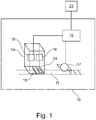
- Fig. 1 shows a machine 10 of the tobacco processing industry, in which a printable or printed material strip 11, for example a paper strip, is processed endlessly.
- the machine 10 comprises a sensor arrangement 14 with an optical camera 15, which is arranged in the machine 10 for imaging the printed side of the material strip 11.
- the camera 15 is a line scan camera.
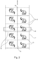
- the line camera 15 extends over the entire width of the material strip 11, as in Fig. 2 is shown.
- the printed side of the material strip 11 would be in the example Fig. 1 directed upwards, ie facing the sensor arrangement 14.
- the machine 10 further comprises a machine control 16 and a cutting device 17 for cutting the material strip 11 along periodically repeating cutting lines 14, see Fig. 2 .
- a preferably touch-sensitive screen terminal 23 is expediently provided for operating the machine 10.
- a covering paper strip 11 printed with an advertising motif 13, here an elephant is shown, which is processed, for example, in a filter applicator 10.
- the topping paper 11 processed here in double width each has areas 12 assigned to a cigarette, the advertising motif 13 being repeated identically in each area 12.
- the advertising motif 13 is thus repeated periodically or equidistantly in the conveying direction.
- the conveying direction of the material strip 11 is in Fig. 2 marked by an arrow as an example.
- the areas 12 are separated from one another by section lines 14 perpendicular to the conveying direction and section lines 35 along the conveying direction.
- the continuous material strip 11 is cut into double-width covering paper sections in the machine 10 by means of the cutting device 17 along the cutting lines 14.
- the advertising motif 13 is arranged in an area of the topping paper that is visible to the outside after the cigarette is finished, in particular in a central region of the corresponding area 12 of the topping paper. Visible from the outside means in particular that the advertising motif 13 is not covered after the cigarette is finished, ie is not covered by a layer of paper.
- the cutting device 17 is continuously controlled by the machine control 16 to ensure that the cutting lines 14 lie exactly at the intended positions between the advertising motifs, and in the worst case the advertising motif is not cut.
- the precise position of the material strip 11 in the machine 10 is continuously determined by means of the sensor arrangement 14.
- the sensor arrangement 14 comprises an electronic data processing device 18 based on, for example, a microprocessor or microcontroller and an electronic memory 19.
- the image 19 of a print pattern (target pattern) to be recognized on the material strip 11 is stored in the memory 19.
- the data processing device 18 contains image recognition software in order to recognize the print pattern stored in the memory in the image data transmitted by the camera system 15 and to determine the position of the print pattern and thus the position of the material strip 11 in the machine 10 therefrom.
- the image recognition software in particular compares the image data recorded with the camera system 15 with the target print pattern stored in the memory 19.
- the determined position of the material strip 11 is sent to the machine control 16, which controls the cutting device 17 precisely on this basis or regulates.
- the measurement resolution of the sensor arrangement 14 is preferably specified by means of an external clock.
- the clock generator can be, for example, a separate rotary encoder 25.
- the cycle can be generated, for example, by a controlled rotary drive of the machine 10, the positional relationship being given by the time-distance relationship
- the sensor arrangement 14 preferably comprises an illumination device 24, preferably a white light source, for illuminating the material strip 11 in the area detected by the sensor arrangement 14.
- the contrast of the image can be significantly increased by the sensor arrangement 14 by means of the illumination device 24.
- no additional printed mark for example a plain-colored rectangle, is used as the print pattern to be recognized by the manufacturer, but rather a suitable, sufficiently high-contrast part of the advertising motif 13, which is present anyway Fig. 2 for example, the trunk, the outstretched leg or the entire elephant.
- An additional print mark is therefore no longer required, and most of the area 12 is available for advertising printing.
- the sensor arrangement 14 does not have to be adapted to the print pattern to be recognized.
- the print pattern to be recognized is in particular a pattern visible to the consumer on the end product.
- the print pattern to be recognized is newly defined in the sensor arrangement 14 and stored in the memory.
- the data processing device 18 preferably comprises a learning module or a learning software for automatically determining a suitable one to be recognized (Target) pressure pattern is set up on the basis of the signal transmitted by the camera system 15.
- a test run of the machine 10 is preferably carried out to teach in the print pattern to be recognized.
- semi-automatic or manual teaching is also possible. In the case of semi-automatic teaching-in, the operator could, for example, see a plurality of possible print patterns on the screen terminal, the operator selecting a print pattern.
- An image of the material strip 11 with the taught-in print pattern can be displayed on the screen terminal 23 in order to facilitate the sensor adjustment, the representation of the switching point and any change in position of the switching point in the conveying direction for the operator. In this way, the operator can easily set the cutting position of the cuts 14 via the screen terminal 23.
- a visualization of the quality of the print pattern to be determined and the reading out of diagnostic data, such as, for example, detection reliability, is also easily possible using the screen terminal 23.
- the learning software used is based, for example, on a neural network or another algorithmic learning method.
- the learning method preferably includes a plausibility check to the effect that the repetition rate of the taught pattern corresponds to the format cycle.
- the learning method can include a filter that only allows a pattern to be taught in from the outset at a repetition rate that corresponds to the format cycle. The repetition rate becomes more general of the format when teaching the pattern into the learning process.
- the determination of the pressure pattern to be recognized in the sensor arrangement 14, in particular after a format change, is not limited to the above method, in particular the sensor arrangement 14 does not necessarily have to comprise a learning module. It is also possible, for example, that a suitable print pattern for each possible format has already been taught in beforehand and has been stored in a database.
- the database can be an external database and / or can be stored in the sensor arrangement 14, in particular in the memory 18, and / or in the machine control 16.
- the described pre-teaching can take place with the sensor arrangement 14, but also with another sensor arrangement, in particular also by means of a laboratory device.
- the print pattern to be recognized can be defined in the sensor arrangement 14 depending on the format.
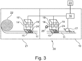
- the machine arrangement 20 here comprises a machine 10 as in FIG Fig. 1 and a bobbin loader 21 with a bobbin 22.
- the bobbin loader 21 is set up for automatically connecting a material strip 11 from an unused bobbin 22 to a material strip from a used bobbin 22 in the production operation.
- a sensor arrangement 14 ' is arranged in the bobbin loader 21, which is constructed in the same way as that in FIG Fig. 1 sensor arrangement 14 shown and with the same Reference to the printable or printed side of the material strip arranged.
- the sensor arrangement 14 ′ can be connected to the machine control 16 of the machine 10.
- the sensor arrangement 14 ′ can be connected to a separate electronic control device of the reel loader 21, which is expediently connected to the control device 16 of the machine 10.
- the sensor arrangement 14 ′ continuously provides a position signal about the position of the material strip 11 in the reel loader 11. In particular after a change of the bobbin 22, this position signal is available as quickly as possible.
- the sensor arrangement 14 is preferably synchronized with the sensor arrangement 14 'on the print pattern to be recognized.
- a print pattern to be recognized by means of the sensor arrangement 14 can in particular be stored in the sensor arrangement 14 ′ via the control device 16 and vice versa.
- the embodiment according to Fig. 3 comprises a plurality of sensor arrangements 14, 14 'in the machine arrangement 20.
- the machine arrangement 20 comprises only one sensor arrangement 14 or 14' in one of the machines 10, 21.
Landscapes
- Wrapping Of Specific Fragile Articles (AREA)
- Length Measuring Devices By Optical Means (AREA)
- Manufacturing Of Cigar And Cigarette Tobacco (AREA)
- Auxiliary Devices For And Details Of Packaging Control (AREA)
Priority Applications (1)
| Application Number | Priority Date | Filing Date | Title |
|---|---|---|---|
| PL13190814T PL2727481T3 (pl) | 2012-11-06 | 2013-10-30 | Sposób odczytu położenia zadrukowanego wstępnie pasa materiału w maszynie przemysłu tytoniowego i maszyna przemysłu tytoniowego |
Applications Claiming Priority (1)
| Application Number | Priority Date | Filing Date | Title |
|---|---|---|---|
| DE102012220155.6A DE102012220155A1 (de) | 2012-11-06 | 2012-11-06 | Verfahren zur Erfassung der Lage eines vorbedruckten Materialstreifens in einer Maschine der Tabak verarbeitenden Industrie, und Maschine der Tabak verarbeitenden Industrie |
Publications (3)
| Publication Number | Publication Date |
|---|---|
| EP2727481A2 EP2727481A2 (de) | 2014-05-07 |
| EP2727481A3 EP2727481A3 (de) | 2018-01-03 |
| EP2727481B1 true EP2727481B1 (de) | 2020-07-01 |
Family
ID=49513796
Family Applications (1)
| Application Number | Title | Priority Date | Filing Date |
|---|---|---|---|
| EP13190814.7A Active EP2727481B1 (de) | 2012-11-06 | 2013-10-30 | Verfahren zur erfassung der lage eines vorbedruckten materialstreifens in einer maschine der tabak verarbeitenden industrie, und maschine der tabak verarbeitenden industrie |
Country Status (4)
| Country | Link |
|---|---|
| EP (1) | EP2727481B1 (pt-PT) |
| CN (1) | CN103808261B (pt-PT) |
| DE (1) | DE102012220155A1 (pt-PT) |
| PL (1) | PL2727481T3 (pt-PT) |
Families Citing this family (7)
| Publication number | Priority date | Publication date | Assignee | Title |
|---|---|---|---|---|
| EP2990366A1 (en) * | 2014-08-12 | 2016-03-02 | Bell and Howell, LLC | Systems, methods, and computer readable media for sheet registration in a tractorless sheet processing device using at least one existing sheet feature |
| DE102016005173A1 (de) * | 2016-04-29 | 2017-11-02 | Focke & Co. (Gmbh & Co. Kg) | Verfahren zur Prüfung von Zigaretten oder Zigarettenpackungen |
| DE102017118083B4 (de) | 2017-08-09 | 2022-11-24 | Sick Ag | Sensor zur Erfassung eines Objekts und Verfahren zum Einstellen eines Schaltpunktes |
| IT201800001948A1 (it) * | 2018-01-30 | 2019-07-30 | Gd Spa | Macchina e metodo per la realizzazione di fascette di incarto per l’industria del tabacco |
| IT201800006360A1 (it) * | 2018-06-18 | 2019-12-18 | Metodo per la lavorazione di un nastro di materiale di incarto per realizzare articoli da fumo | |
| JP7084841B2 (ja) * | 2018-10-12 | 2022-06-15 | 住友重機械工業株式会社 | 制御装置、画像情報取得装置システム、撮像制御システム及び印刷システム |
| EP4101647A1 (de) * | 2021-06-11 | 2022-12-14 | BST GmbH | Verfahren zum digitaldruck auf einer laufenden bedruckstoffbahn |
Family Cites Families (16)
| Publication number | Priority date | Publication date | Assignee | Title |
|---|---|---|---|---|
| DE1805075A1 (de) | 1968-10-25 | 1970-09-03 | Hauni Werke Koerber & Co Kg | Verfahren und Vorrichtung zum UEberwachen von Markierungen auf stabfoermigen Tabakartikeln,vorzugsweise der Druckbilder auf Zigaretten |
| CN1049182C (zh) * | 1992-09-19 | 2000-02-09 | 琳得科株式会社 | 用于印刷装置的模切装置 |
| ITBO940153A1 (it) * | 1994-04-12 | 1995-10-12 | Gd Spa | Metodo per il controllo ottico di prodotti. |
| DE19939667A1 (de) | 1999-08-20 | 2001-02-22 | Hauni Maschinenbau Ag | Verfahren und Vorrichtung zum Prüfen der Qualität eines Aufdruckes |
| DE19951140A1 (de) * | 1999-10-23 | 2001-04-26 | Hauni Maschinenbau Ag | Verfahren und Vorrichtung zum Prüfen der Unversehrtheit einer Packung, insbesondere einer Zigarettenpackung |
| DE10028000A1 (de) * | 2000-06-08 | 2001-12-13 | Hauni Maschinenbau Ag | Verfahren und Vorrichtung zum Zuführen eines abschnittweise perforierten Belagpapierstreifens für ventilierte Zigaretten |
| DE10241127A1 (de) | 2002-09-03 | 2004-03-11 | Hauni Maschinenbau Ag | Druckbildüberwachung und -erkennung auf Zigaretten |
| JP2005081544A (ja) * | 2003-09-04 | 2005-03-31 | Frontier System:Kk | 印刷物の印刷不良検査装置 |
| CN201165081Y (zh) * | 2007-01-19 | 2008-12-17 | 长春市吉海测控技术有限责任公司 | 利用摄像机进行印刷机自动裁切控制的装置 |
| GB0809135D0 (en) * | 2008-05-20 | 2008-06-25 | British American Tobacco Co | Apparatus and method for making a smoking article |
| EP2128793B1 (de) * | 2008-05-28 | 2012-10-17 | Pepperl + Fuchs GmbH | Verfahren und Vorrichtung zum Überprüfen von Druckerzeugnissen, Computerprogramm und Computerprogrammprodukt |
| CN201329696Y (zh) * | 2008-09-08 | 2009-10-21 | 宋宝富 | 模切机定位在线检测控制系统 |
| IT1393013B1 (it) * | 2008-12-18 | 2012-04-11 | Gd Spa | Metodo per la messa a punto e la gestione del dispositivo di controllo in una macchina per la produzione di articoli da fumo. |
| DE202009012142U1 (de) * | 2009-09-07 | 2011-02-03 | Sick Ag | Optoelektronischer Sensor zur Streifenerkennung |
| CN101658327A (zh) * | 2009-09-13 | 2010-03-03 | 周冬莲 | 卷接机在线钢印检测油墨控制与切口自动纠偏系统 |
| CN201571490U (zh) * | 2009-12-17 | 2010-09-08 | 上海烟草(集团)公司 | 针对gd121卷烟机组的烟支钢印在线检测系统 |
-
2012
- 2012-11-06 DE DE102012220155.6A patent/DE102012220155A1/de not_active Ceased
-
2013
- 2013-10-30 PL PL13190814T patent/PL2727481T3/pl unknown
- 2013-10-30 EP EP13190814.7A patent/EP2727481B1/de active Active
- 2013-11-05 CN CN201310612894.5A patent/CN103808261B/zh active Active
Non-Patent Citations (1)
| Title |
|---|
| None * |
Also Published As
| Publication number | Publication date |
|---|---|
| CN103808261A (zh) | 2014-05-21 |
| PL2727481T3 (pl) | 2020-11-30 |
| CN103808261B (zh) | 2019-04-16 |
| DE102012220155A1 (de) | 2014-05-08 |
| EP2727481A3 (de) | 2018-01-03 |
| EP2727481A2 (de) | 2014-05-07 |
Similar Documents
| Publication | Publication Date | Title |
|---|---|---|
| EP2727481B1 (de) | Verfahren zur erfassung der lage eines vorbedruckten materialstreifens in einer maschine der tabak verarbeitenden industrie, und maschine der tabak verarbeitenden industrie | |
| EP2739167B1 (de) | Verfahren und vorrichtung zur optischen prüfung von bei der herstellung und/oder verpackung von zigaretten zu prüfenden objekten | |
| DE3015159A1 (de) | Verfahren und vorrichtung zum einstellen eines druckmusters auf ein material | |
| EP1308274B1 (de) | Vorrichtung und Verfahren zur Positionierung eines Querschnitts auf einem Bedruckstoff in Rollendruckmaschinen | |
| DE102005004972A1 (de) | Registerverfahren | |
| EP2705756B1 (de) | Aufhängevorrichtung sowie Verfahren zum Aufhängen von Würsten, insbesondere Wurstketten | |
| WO2003097357A2 (de) | Vorrichtung und verfahren zum positionieren eines zu bedruckenden substrats | |
| DE102008024104A1 (de) | Materialmarkensensor und Verfahren zum Erfassen einer Markierung auf oder in einem Material | |
| DE102015116198A1 (de) | Verfahren zur automatisierten Einstellung eines Spaltmaßes, diesbezügliche Steueranlage und Stanzvorrichtung | |
| EP2902203B1 (de) | Verfahren und Vorrichtung zur Steuerung und Regelung eines digitalen Druckprozesses | |
| EP1403045B1 (de) | Verfahren und Vorrichtung zur Bestimmung der Position und/oder Form von Marken auf einer bedruckten Papierbahn | |
| DE102011014073A1 (de) | Verfahren zur Regelung eines Druckvorgangs | |
| EP3092970B1 (de) | Verfahren und vorrichtung zur ansteuerung einer operationsleuchte | |
| EP0790187A2 (de) | Verfahren und Vorrichtung zur Kontrolle von Zuschnitten oder Banderolen für Zigarettenpackungen | |
| EP1623943B1 (de) | Vorrichtung und Verfahren zur Erfassung eines Merkmals einer laufenden Materialbahn | |
| DE602004007021T2 (de) | Verfahren zum kalibrieren einer brillenlinsendurchdringungsmaschine, einrichtung zur implementierung eines solchen verfahrens und eine solche einrichtung umfassende brillenlinsenbearbeitungs-vorrichtung | |
| DE102007007828A1 (de) | Verfahren und Vorrichtung zum Beleuchten eines Druckbildes auf einer Materialbahn | |
| DE102005000953A1 (de) | Verfahren zum Kennzeichnen von geräucherten Lebensmitteln | |
| DE19730627A1 (de) | Verfahren und Anordnung zur Steuerung einer Druckmaschine | |
| DE102017120419A1 (de) | Verfahren und Einrichtung zur Herstellung eines Klebebandes | |
| DE102014208206A1 (de) | Verfahren zum Steuern, Parametrisieren oder Kalibrieren einer zur Beleuchtungssteuerung genutzten Sensoreinheit | |
| DE102009017464B4 (de) | Vorrichtung zum optischen Inspizieren einer Oberfläche an einem Gegenstand | |
| DE102013209772B4 (de) | Verfahren zum Nachdrucken mindestens eines individualisierten Druckexemplars | |
| DE102011000316B4 (de) | Verfahren für die Kalibrierung einer vertikalen Hell-Dunkel-Grenze sowie Fahrzeuge mit einer variierbaren Hell-Dunkel-Grenze | |
| WO2020207841A1 (de) | Vorrichtung zur druckbildkontrolle und verfahren zur validierung von inspektionsalgorithmen |
Legal Events
| Date | Code | Title | Description |
|---|---|---|---|
| PUAI | Public reference made under article 153(3) epc to a published international application that has entered the european phase |
Free format text: ORIGINAL CODE: 0009012 |
|
| 17P | Request for examination filed |
Effective date: 20131030 |
|
| AK | Designated contracting states |
Kind code of ref document: A2 Designated state(s): AL AT BE BG CH CY CZ DE DK EE ES FI FR GB GR HR HU IE IS IT LI LT LU LV MC MK MT NL NO PL PT RO RS SE SI SK SM TR |
|
| AX | Request for extension of the european patent |
Extension state: BA ME |
|
| RAP1 | Party data changed (applicant data changed or rights of an application transferred) |
Owner name: HAUNI MASCHINENBAU GMBH |
|
| PUAL | Search report despatched |
Free format text: ORIGINAL CODE: 0009013 |
|
| AK | Designated contracting states |
Kind code of ref document: A3 Designated state(s): AL AT BE BG CH CY CZ DE DK EE ES FI FR GB GR HR HU IE IS IT LI LT LU LV MC MK MT NL NO PL PT RO RS SE SI SK SM TR |
|
| AX | Request for extension of the european patent |
Extension state: BA ME |
|
| RIC1 | Information provided on ipc code assigned before grant |
Ipc: A24C 5/00 20060101ALI20171124BHEP Ipc: A24C 5/34 20060101ALI20171124BHEP Ipc: B65H 43/08 20060101ALI20171124BHEP Ipc: B65H 23/04 20060101ALI20171124BHEP Ipc: A24C 5/47 20060101AFI20171124BHEP Ipc: B65H 35/04 20060101ALI20171124BHEP |
|
| STAA | Information on the status of an ep patent application or granted ep patent |
Free format text: STATUS: REQUEST FOR EXAMINATION WAS MADE |
|
| 17P | Request for examination filed |
Effective date: 20180620 |
|
| RBV | Designated contracting states (corrected) |
Designated state(s): AL AT BE BG CH CY CZ DE DK EE ES FI FR GB GR HR HU IE IS IT LI LT LU LV MC MK MT NL NO PL PT RO RS SE SI SK SM TR |
|
| GRAP | Despatch of communication of intention to grant a patent |
Free format text: ORIGINAL CODE: EPIDOSNIGR1 |
|
| STAA | Information on the status of an ep patent application or granted ep patent |
Free format text: STATUS: GRANT OF PATENT IS INTENDED |
|
| INTG | Intention to grant announced |
Effective date: 20200122 |
|
| GRAS | Grant fee paid |
Free format text: ORIGINAL CODE: EPIDOSNIGR3 |
|
| GRAA | (expected) grant |
Free format text: ORIGINAL CODE: 0009210 |
|
| STAA | Information on the status of an ep patent application or granted ep patent |
Free format text: STATUS: THE PATENT HAS BEEN GRANTED |
|
| AK | Designated contracting states |
Kind code of ref document: B1 Designated state(s): AL AT BE BG CH CY CZ DE DK EE ES FI FR GB GR HR HU IE IS IT LI LT LU LV MC MK MT NL NO PL PT RO RS SE SI SK SM TR |
|
| REG | Reference to a national code |
Ref country code: CH Ref legal event code: EP Ref country code: AT Ref legal event code: REF Ref document number: 1285279 Country of ref document: AT Kind code of ref document: T Effective date: 20200715 |
|
| REG | Reference to a national code |
Ref country code: IE Ref legal event code: FG4D Free format text: LANGUAGE OF EP DOCUMENT: GERMAN |
|
| REG | Reference to a national code |
Ref country code: DE Ref legal event code: R096 Ref document number: 502013014862 Country of ref document: DE |
|
| REG | Reference to a national code |
Ref country code: NL Ref legal event code: FP |
|
| REG | Reference to a national code |
Ref country code: LT Ref legal event code: MG4D |
|
| PG25 | Lapsed in a contracting state [announced via postgrant information from national office to epo] |
Ref country code: BG Free format text: LAPSE BECAUSE OF FAILURE TO SUBMIT A TRANSLATION OF THE DESCRIPTION OR TO PAY THE FEE WITHIN THE PRESCRIBED TIME-LIMIT Effective date: 20201001 |
|
| PG25 | Lapsed in a contracting state [announced via postgrant information from national office to epo] |
Ref country code: PT Free format text: LAPSE BECAUSE OF FAILURE TO SUBMIT A TRANSLATION OF THE DESCRIPTION OR TO PAY THE FEE WITHIN THE PRESCRIBED TIME-LIMIT Effective date: 20201102 Ref country code: HR Free format text: LAPSE BECAUSE OF FAILURE TO SUBMIT A TRANSLATION OF THE DESCRIPTION OR TO PAY THE FEE WITHIN THE PRESCRIBED TIME-LIMIT Effective date: 20200701 Ref country code: SE Free format text: LAPSE BECAUSE OF FAILURE TO SUBMIT A TRANSLATION OF THE DESCRIPTION OR TO PAY THE FEE WITHIN THE PRESCRIBED TIME-LIMIT Effective date: 20200701 Ref country code: ES Free format text: LAPSE BECAUSE OF FAILURE TO SUBMIT A TRANSLATION OF THE DESCRIPTION OR TO PAY THE FEE WITHIN THE PRESCRIBED TIME-LIMIT Effective date: 20200701 Ref country code: LT Free format text: LAPSE BECAUSE OF FAILURE TO SUBMIT A TRANSLATION OF THE DESCRIPTION OR TO PAY THE FEE WITHIN THE PRESCRIBED TIME-LIMIT Effective date: 20200701 Ref country code: CZ Free format text: LAPSE BECAUSE OF FAILURE TO SUBMIT A TRANSLATION OF THE DESCRIPTION OR TO PAY THE FEE WITHIN THE PRESCRIBED TIME-LIMIT Effective date: 20200701 Ref country code: FI Free format text: LAPSE BECAUSE OF FAILURE TO SUBMIT A TRANSLATION OF THE DESCRIPTION OR TO PAY THE FEE WITHIN THE PRESCRIBED TIME-LIMIT Effective date: 20200701 Ref country code: NO Free format text: LAPSE BECAUSE OF FAILURE TO SUBMIT A TRANSLATION OF THE DESCRIPTION OR TO PAY THE FEE WITHIN THE PRESCRIBED TIME-LIMIT Effective date: 20201001 Ref country code: GR Free format text: LAPSE BECAUSE OF FAILURE TO SUBMIT A TRANSLATION OF THE DESCRIPTION OR TO PAY THE FEE WITHIN THE PRESCRIBED TIME-LIMIT Effective date: 20201002 |
|
| PG25 | Lapsed in a contracting state [announced via postgrant information from national office to epo] |
Ref country code: LV Free format text: LAPSE BECAUSE OF FAILURE TO SUBMIT A TRANSLATION OF THE DESCRIPTION OR TO PAY THE FEE WITHIN THE PRESCRIBED TIME-LIMIT Effective date: 20200701 Ref country code: RS Free format text: LAPSE BECAUSE OF FAILURE TO SUBMIT A TRANSLATION OF THE DESCRIPTION OR TO PAY THE FEE WITHIN THE PRESCRIBED TIME-LIMIT Effective date: 20200701 Ref country code: IS Free format text: LAPSE BECAUSE OF FAILURE TO SUBMIT A TRANSLATION OF THE DESCRIPTION OR TO PAY THE FEE WITHIN THE PRESCRIBED TIME-LIMIT Effective date: 20201101 |
|
| REG | Reference to a national code |
Ref country code: DE Ref legal event code: R097 Ref document number: 502013014862 Country of ref document: DE |
|
| PG25 | Lapsed in a contracting state [announced via postgrant information from national office to epo] |
Ref country code: EE Free format text: LAPSE BECAUSE OF FAILURE TO SUBMIT A TRANSLATION OF THE DESCRIPTION OR TO PAY THE FEE WITHIN THE PRESCRIBED TIME-LIMIT Effective date: 20200701 Ref country code: DK Free format text: LAPSE BECAUSE OF FAILURE TO SUBMIT A TRANSLATION OF THE DESCRIPTION OR TO PAY THE FEE WITHIN THE PRESCRIBED TIME-LIMIT Effective date: 20200701 Ref country code: SM Free format text: LAPSE BECAUSE OF FAILURE TO SUBMIT A TRANSLATION OF THE DESCRIPTION OR TO PAY THE FEE WITHIN THE PRESCRIBED TIME-LIMIT Effective date: 20200701 Ref country code: RO Free format text: LAPSE BECAUSE OF FAILURE TO SUBMIT A TRANSLATION OF THE DESCRIPTION OR TO PAY THE FEE WITHIN THE PRESCRIBED TIME-LIMIT Effective date: 20200701 |
|
| PLBE | No opposition filed within time limit |
Free format text: ORIGINAL CODE: 0009261 |
|
| STAA | Information on the status of an ep patent application or granted ep patent |
Free format text: STATUS: NO OPPOSITION FILED WITHIN TIME LIMIT |
|
| PG25 | Lapsed in a contracting state [announced via postgrant information from national office to epo] |
Ref country code: AL Free format text: LAPSE BECAUSE OF FAILURE TO SUBMIT A TRANSLATION OF THE DESCRIPTION OR TO PAY THE FEE WITHIN THE PRESCRIBED TIME-LIMIT Effective date: 20200701 |
|
| REG | Reference to a national code |
Ref country code: CH Ref legal event code: PL |
|
| 26N | No opposition filed |
Effective date: 20210406 |
|
| GBPC | Gb: european patent ceased through non-payment of renewal fee |
Effective date: 20201030 |
|
| PG25 | Lapsed in a contracting state [announced via postgrant information from national office to epo] |
Ref country code: LU Free format text: LAPSE BECAUSE OF NON-PAYMENT OF DUE FEES Effective date: 20201030 Ref country code: MC Free format text: LAPSE BECAUSE OF FAILURE TO SUBMIT A TRANSLATION OF THE DESCRIPTION OR TO PAY THE FEE WITHIN THE PRESCRIBED TIME-LIMIT Effective date: 20200701 Ref country code: SK Free format text: LAPSE BECAUSE OF FAILURE TO SUBMIT A TRANSLATION OF THE DESCRIPTION OR TO PAY THE FEE WITHIN THE PRESCRIBED TIME-LIMIT Effective date: 20200701 |
|
| REG | Reference to a national code |
Ref country code: BE Ref legal event code: MM Effective date: 20201031 |
|
| PG25 | Lapsed in a contracting state [announced via postgrant information from national office to epo] |
Ref country code: FR Free format text: LAPSE BECAUSE OF NON-PAYMENT OF DUE FEES Effective date: 20201031 |
|
| PG25 | Lapsed in a contracting state [announced via postgrant information from national office to epo] |
Ref country code: BE Free format text: LAPSE BECAUSE OF NON-PAYMENT OF DUE FEES Effective date: 20201031 Ref country code: CH Free format text: LAPSE BECAUSE OF NON-PAYMENT OF DUE FEES Effective date: 20201031 Ref country code: SI Free format text: LAPSE BECAUSE OF FAILURE TO SUBMIT A TRANSLATION OF THE DESCRIPTION OR TO PAY THE FEE WITHIN THE PRESCRIBED TIME-LIMIT Effective date: 20200701 Ref country code: LI Free format text: LAPSE BECAUSE OF NON-PAYMENT OF DUE FEES Effective date: 20201031 Ref country code: GB Free format text: LAPSE BECAUSE OF NON-PAYMENT OF DUE FEES Effective date: 20201030 |
|
| PG25 | Lapsed in a contracting state [announced via postgrant information from national office to epo] |
Ref country code: IE Free format text: LAPSE BECAUSE OF NON-PAYMENT OF DUE FEES Effective date: 20201030 |
|
| REG | Reference to a national code |
Ref country code: AT Ref legal event code: MM01 Ref document number: 1285279 Country of ref document: AT Kind code of ref document: T Effective date: 20201030 |
|
| PG25 | Lapsed in a contracting state [announced via postgrant information from national office to epo] |
Ref country code: AT Free format text: LAPSE BECAUSE OF NON-PAYMENT OF DUE FEES Effective date: 20201030 |
|
| PG25 | Lapsed in a contracting state [announced via postgrant information from national office to epo] |
Ref country code: TR Free format text: LAPSE BECAUSE OF FAILURE TO SUBMIT A TRANSLATION OF THE DESCRIPTION OR TO PAY THE FEE WITHIN THE PRESCRIBED TIME-LIMIT Effective date: 20200701 Ref country code: MT Free format text: LAPSE BECAUSE OF FAILURE TO SUBMIT A TRANSLATION OF THE DESCRIPTION OR TO PAY THE FEE WITHIN THE PRESCRIBED TIME-LIMIT Effective date: 20200701 Ref country code: CY Free format text: LAPSE BECAUSE OF FAILURE TO SUBMIT A TRANSLATION OF THE DESCRIPTION OR TO PAY THE FEE WITHIN THE PRESCRIBED TIME-LIMIT Effective date: 20200701 |
|
| PG25 | Lapsed in a contracting state [announced via postgrant information from national office to epo] |
Ref country code: MK Free format text: LAPSE BECAUSE OF FAILURE TO SUBMIT A TRANSLATION OF THE DESCRIPTION OR TO PAY THE FEE WITHIN THE PRESCRIBED TIME-LIMIT Effective date: 20200701 |
|
| REG | Reference to a national code |
Ref country code: DE Ref legal event code: R081 Ref document number: 502013014862 Country of ref document: DE Owner name: KOERBER TECHNOLOGIES GMBH, DE Free format text: FORMER OWNER: HAUNI MASCHINENBAU GMBH, 21033 HAMBURG, DE |
|
| REG | Reference to a national code |
Ref country code: NL Ref legal event code: HC Owner name: KOERBER TECHNOLOGIES GMBH; DE Free format text: DETAILS ASSIGNMENT: CHANGE OF OWNER(S), CHANGE OF OWNER(S) NAME; FORMER OWNER NAME: HAUNI MASCHINENBAU GMBH Effective date: 20221031 |
|
| P01 | Opt-out of the competence of the unified patent court (upc) registered |
Effective date: 20230621 |
|
| PGFP | Annual fee paid to national office [announced via postgrant information from national office to epo] |
Ref country code: PL Payment date: 20230920 Year of fee payment: 11 Ref country code: NL Payment date: 20231023 Year of fee payment: 11 |
|
| PGFP | Annual fee paid to national office [announced via postgrant information from national office to epo] |
Ref country code: IT Payment date: 20231030 Year of fee payment: 11 Ref country code: DE Payment date: 20231030 Year of fee payment: 11 |