EP2721317B1 - Torsionsdämpfer mit in relation zu den führungsscheiben achsversetzten pendelartigen fliehgewichten - Google Patents
Torsionsdämpfer mit in relation zu den führungsscheiben achsversetzten pendelartigen fliehgewichten Download PDFInfo
- Publication number
- EP2721317B1 EP2721317B1 EP12725479.5A EP12725479A EP2721317B1 EP 2721317 B1 EP2721317 B1 EP 2721317B1 EP 12725479 A EP12725479 A EP 12725479A EP 2721317 B1 EP2721317 B1 EP 2721317B1
- Authority
- EP
- European Patent Office
- Prior art keywords
- phasing
- support element
- radial
- axially
- washer
- Prior art date
- Legal status (The legal status is an assumption and is not a legal conclusion. Google has not performed a legal analysis and makes no representation as to the accuracy of the status listed.)
- Active
Links
Images


Classifications
-
- F—MECHANICAL ENGINEERING; LIGHTING; HEATING; WEAPONS; BLASTING
- F16—ENGINEERING ELEMENTS AND UNITS; GENERAL MEASURES FOR PRODUCING AND MAINTAINING EFFECTIVE FUNCTIONING OF MACHINES OR INSTALLATIONS; THERMAL INSULATION IN GENERAL
- F16F—SPRINGS; SHOCK-ABSORBERS; MEANS FOR DAMPING VIBRATION
- F16F15/00—Suppression of vibrations in systems; Means or arrangements for avoiding or reducing out-of-balance forces, e.g. due to motion
- F16F15/10—Suppression of vibrations in rotating systems by making use of members moving with the system
- F16F15/12—Suppression of vibrations in rotating systems by making use of members moving with the system using elastic members or friction-damping members, e.g. between a rotating shaft and a gyratory mass mounted thereon
- F16F15/121—Suppression of vibrations in rotating systems by making use of members moving with the system using elastic members or friction-damping members, e.g. between a rotating shaft and a gyratory mass mounted thereon using springs as elastic members, e.g. metallic springs
- F16F15/123—Wound springs
- F16F15/12353—Combinations of dampers, e.g. with multiple plates, multiple spring sets, i.e. complex configurations
-
- F—MECHANICAL ENGINEERING; LIGHTING; HEATING; WEAPONS; BLASTING
- F16—ENGINEERING ELEMENTS AND UNITS; GENERAL MEASURES FOR PRODUCING AND MAINTAINING EFFECTIVE FUNCTIONING OF MACHINES OR INSTALLATIONS; THERMAL INSULATION IN GENERAL
- F16D—COUPLINGS FOR TRANSMITTING ROTATION; CLUTCHES; BRAKES
- F16D3/00—Yielding couplings, i.e. with means permitting movement between the connected parts during the drive
- F16D3/02—Yielding couplings, i.e. with means permitting movement between the connected parts during the drive adapted to specific functions
- F16D3/12—Yielding couplings, i.e. with means permitting movement between the connected parts during the drive adapted to specific functions specially adapted for accumulation of energy to absorb shocks or vibration
-
- F—MECHANICAL ENGINEERING; LIGHTING; HEATING; WEAPONS; BLASTING
- F16—ENGINEERING ELEMENTS AND UNITS; GENERAL MEASURES FOR PRODUCING AND MAINTAINING EFFECTIVE FUNCTIONING OF MACHINES OR INSTALLATIONS; THERMAL INSULATION IN GENERAL
- F16F—SPRINGS; SHOCK-ABSORBERS; MEANS FOR DAMPING VIBRATION
- F16F15/00—Suppression of vibrations in systems; Means or arrangements for avoiding or reducing out-of-balance forces, e.g. due to motion
- F16F15/10—Suppression of vibrations in rotating systems by making use of members moving with the system
- F16F15/12—Suppression of vibrations in rotating systems by making use of members moving with the system using elastic members or friction-damping members, e.g. between a rotating shaft and a gyratory mass mounted thereon
- F16F15/121—Suppression of vibrations in rotating systems by making use of members moving with the system using elastic members or friction-damping members, e.g. between a rotating shaft and a gyratory mass mounted thereon using springs as elastic members, e.g. metallic springs
- F16F15/123—Wound springs
- F16F15/12353—Combinations of dampers, e.g. with multiple plates, multiple spring sets, i.e. complex configurations
- F16F15/1236—Combinations of dampers, e.g. with multiple plates, multiple spring sets, i.e. complex configurations resulting in a staged spring characteristic, e.g. with multiple intermediate plates
- F16F15/12366—Combinations of dampers, e.g. with multiple plates, multiple spring sets, i.e. complex configurations resulting in a staged spring characteristic, e.g. with multiple intermediate plates acting on multiple sets of springs
- F16F15/12373—Combinations of dampers, e.g. with multiple plates, multiple spring sets, i.e. complex configurations resulting in a staged spring characteristic, e.g. with multiple intermediate plates acting on multiple sets of springs the sets of springs being arranged at substantially the same radius
-
- F—MECHANICAL ENGINEERING; LIGHTING; HEATING; WEAPONS; BLASTING
- F16—ENGINEERING ELEMENTS AND UNITS; GENERAL MEASURES FOR PRODUCING AND MAINTAINING EFFECTIVE FUNCTIONING OF MACHINES OR INSTALLATIONS; THERMAL INSULATION IN GENERAL
- F16F—SPRINGS; SHOCK-ABSORBERS; MEANS FOR DAMPING VIBRATION
- F16F15/00—Suppression of vibrations in systems; Means or arrangements for avoiding or reducing out-of-balance forces, e.g. due to motion
- F16F15/10—Suppression of vibrations in rotating systems by making use of members moving with the system
- F16F15/14—Suppression of vibrations in rotating systems by making use of members moving with the system using masses freely rotating with the system, i.e. uninvolved in transmitting driveline torque, e.g. rotative dynamic dampers
- F16F15/1407—Suppression of vibrations in rotating systems by making use of members moving with the system using masses freely rotating with the system, i.e. uninvolved in transmitting driveline torque, e.g. rotative dynamic dampers the rotation being limited with respect to the driving means
- F16F15/145—Masses mounted with play with respect to driving means thus enabling free movement over a limited range
-
- F—MECHANICAL ENGINEERING; LIGHTING; HEATING; WEAPONS; BLASTING
- F16—ENGINEERING ELEMENTS AND UNITS; GENERAL MEASURES FOR PRODUCING AND MAINTAINING EFFECTIVE FUNCTIONING OF MACHINES OR INSTALLATIONS; THERMAL INSULATION IN GENERAL
- F16H—GEARING
- F16H45/00—Combinations of fluid gearings for conveying rotary motion with couplings or clutches
- F16H45/02—Combinations of fluid gearings for conveying rotary motion with couplings or clutches with mechanical clutches for bridging a fluid gearing of the hydrokinetic type
- F16H2045/0221—Combinations of fluid gearings for conveying rotary motion with couplings or clutches with mechanical clutches for bridging a fluid gearing of the hydrokinetic type with damping means
- F16H2045/0263—Combinations of fluid gearings for conveying rotary motion with couplings or clutches with mechanical clutches for bridging a fluid gearing of the hydrokinetic type with damping means the damper comprising a pendulum
Definitions
- the invention relates to a torsion damping device between a motor shaft and a coaxial axially oriented driven shaft in a temporary coupling system of a motor vehicle comprising first damping means by elastic members, and second means damping by pendulum weights.
- Damping devices of this type are equipped, for example, with clutch assemblies with dry or wet friction, or with clutch systems designed to lock a hydrodynamic converter.
- An internal combustion engine has acyclisms due to the succession of explosions in the engine cylinders.
- the torsion damping means make it possible to filter these acyclisms before transmitting the engine torque to a gearbox. It is indeed necessary to dampen the vibrations before they enter the gearbox and cause an unacceptable noise nuisance.
- the torsion damping device is generally arranged in a clutch system which allows the temporary connection in rotation of the drive shaft with the gearbox shaft.
- the torsion damping device generally comprises first damping means by interposition of circumferentially acting resilient members between a torque input member and a torque output member.
- Such first damping means are advantageously supplemented by second damping means by pendular weights.
- pendulum weights also called pendulum oscillators, extend around the axis of rotation of the drive shaft and are free to oscillate about a fictitious axis substantially parallel to the axis of rotation of the motor shaft.
- the pendular masses react to irregularities of rotation, they oscillate so that the center of gravity of each of these masses pendulum oscillates about an axis substantially parallel to the axis of rotation of the motor shaft.
- the pendulum weights are generally located radially above the first damping means.
- the radial size of the pendulum weights is necessarily limited so as not to excessively decrease the implantation diameter of the elastic members and thereby reduce the efficiency of the first damping means.
- the mass of the pendulum weights can be increased only to the detriment of the effectiveness of the damping means with elastic members.
- the invention proposes a damping device of the type described above, characterized in that the support element is offset axially on one and the same side with respect to the peripheral portions of the two guide washers so that the pendulum weight is axially offset. on the same side with respect to the peripheral portions of the two guide washers.
- the invention also relates to a torque converter comprising a splined hub torque input which is integral in rotation with the torque input element, the converter being equipped with a damping device made according to the teachings of the invention.
- a damping device made according to the teachings of the invention.
- invention characterized in that at least one flyweight is arranged radially vis-à-vis the fluted hub.
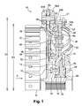
- FIG. 1 a torsion damping device 10 made according to a first embodiment of the invention.
- the damping device 10 is intended to be arranged in a temporary coupling system of a motor vehicle.
- the damping device 10 is here intended to be arranged in a torque converter (not shown) for coupling torsionally damping the casing of the torque converter to a locking clutch of the converter.
- the torsion damping device 10 made according to the teachings of the invention is also applicable to any other type of clutch system.
- the torsion damping device 10 is used to couple a first shaft (not shown) motor and a second shaft (not shown) coaxial driven axis "B" with torsion damping.
- the device 10 comprises a torque output member which is here formed by a radial outlet web 12.
- the sail 12 output has a circular washer shape coaxial with the axis "B".
- the output web 12 is intended to be rotatably connected to the second driven shaft via a driven hub 14.
- the output web 12 is rotatably connected to the driven hub 14 via rivets 15.
- the sail 12 output has three radial tabs (not shown).
- the tabs are arranged regularly around the axis "B" globally at 120 ° from each other.
- Each leg extends radially protruding from the outer peripheral edge 18 of the web 12 output.
- the outer peripheral edge 18 is visible at the figure 1 .
- the damping device 10 further has a torque input member which is formed here by a first radial input washer 20A before and by a second radial input washer 20B rear.
- the input washers 20A, 20B are parallel to each other and they are arranged axially on either side of the web 12 output.
- the rear inlet washer 20B is rotatably connected with the front inlet washer 20A via axial pins 21 which are arranged on an outer edge of the rear inlet washer 20B, as shown in FIG. figure 1 .
- the two input washers 20A, 20B are connected in rotation to the first motor shaft via a hub 22 grooved, also called disc holder, on which is mounted axially movable piston of a clutch lock (not shown, commonly called “lock-up.”
- the "lock-up" piston is movable between a de-coupled position and a bridging position of the converter for coupling the housing of the torque converter to the input shaft.
- the splined hub 22 is arranged at the rear of the damping device 10.
- the rear inlet washer 20B is attached to the splined hub 22 via rivets (not shown).
- Each inlet washer 20A, 20B has a radial flange which is provided with a central passage to allow passage of the driven shaft and the driven hub 14 of the output web 12.
- each inlet washer 20A, 20B further comprises three external pushing tabs 24 which are arranged in coincidence with the tabs of the outlet web 12.
- the legs of the output sail 12 are thus interposed axially between the tabs 24 of the input washers 20A forward and 20B rear.
- the front inlet washer 20A is freely rotatably mounted on a first cylindrical outer face 26 for guiding a central bearing 28.
- the bearing 28 is itself rotatably mounted on an outer cylindrical face 30 of a front section of the driven hub 14.
- the axial displacements of the bearing 28 are limited rearwardly by a shoulder face 32 of the driven hub 14, while they are limited axially forward by an elastic ring 34 which is mounted in a groove of the driven hub 14.
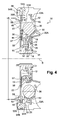
- the inlet washers 20A, 20B and the corrugated hub 22 are furthermore centered with respect to the driven hub 14 via a radial sheet metal plate 57 shown in FIG. figure 4 .
- This plate 57 is sandwiched axially between the splined hub 22 on the one hand and the rear inlet washer 20B on the other.
- the plate 57 is fixed to the spline hub 22 by riveting.
- the plate 57 comprises a central orifice whose periphery is radially in abutment against a bearing surface 59 formed on the hub in order to center the splined hub 22 and the input washers 20A, 20B.
- the damping device 10 further comprises elastic members 36 with circumferential action.
- the damping device 10 here comprises six elastic members 36.
- the elastic members 36 are here formed by helical springs with a main axis of circumferential orientation.
- the elastic members 36 are arranged in a circular row around the peripheral edge 18 of the output web 12.
- the elastic members 36 are here implanted on a circle centered on the axis of rotation "B".
- the resilient members 36 are divided into three groups of two elastic members 36.
- the elastic members 36 of each group are housed circumferentially in series, that is to say end to end, between two legs of the outlet web 12 and between two tabs 24 of the input washers 20A, 20B.
- the two elastic members 36 of each group being connected in series, the two ends facing these two elastic members 36 are able to bear against each other when transmitting a torque between the inlet washers 20A, 20B and the outlet veil 12.
- the guiding and the axial holding in position of the elastic members 36 is carried out by guide washers.
- the guide washers are here formed by the input washers 20A, 20B.
- the inlet washers 20A, 20B are arranged axially on either side of the elastic members 36.
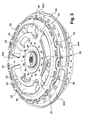
- Each inlet washer 20A, 20B is perforated with three windows 46 each of which is arranged in coincidence with two associated elastic members 36, as shown in FIGS. figures 2 and 3 .
- the windows 46 are separated by the radial tabs 24.
- Each window 46 is capable of housing an axial end portion of the elastic member 36.
- the tongues 50, 52 form axial holding means for the associated elastic member 36.
- the windows 46 thus form housings for receiving the resilient members 36 and the tongues 50, 52 prevent the resilient members 36 to exit axially through the windows 46.
- the elastic members 36 are thus trapped axially between the two inlet washers 20A, 20B.
- each input washer 20A, 20B also forming guide washers, comprises a radial annular peripheral portion 53A, 53B which extends radially outwardly from the outer edge of the windows 46.
- the outer tongue 52 of the windows 46 of the front inlet washer 20A extends axially projecting forward relative to the peripheral portion 53A, while the outer tongue 52 of the windows 46 of the rear inlet washer 20B extends axially projecting rearwardly relative to the peripheral portion 53B,
- Such a phasing member is here formed by a radial phasing washer 38. As illustrated in FIG. figure 1 , the phasing washer 38 is interposed between the input washer 20B back and the veil 12 output.
- the phasing washer 38 is rotatably mounted relative to the outlet web 12, on the one hand, and relative to the input washers 20A, 20B, on the other hand.
- the phasing washer 38 is freely rotatably mounted on a second outer cylindrical surface 42 of the driven hub 14. The phasing washer 38 is thus centered on the driven hub 14.
- the second cylindrical outer face 42 is arranged axially behind the first face cylindrical outer 30.
- the second outer cylindrical face 42 has a diameter smaller than that of the first outer cylindrical face 30 of the driven hub 14.
- the phasing washer 38 is pressed axially rearward against a radial face 44 which is fixed relative to the splined hub 22 or the input washer 20B back. This makes it possible to axially position the phasing washer 38 with respect to the input washers 20A, 20B. In the embodiment shown in detail on the figure 4 , the phasing washer 38 bears against the front face 44 of the plate 57.
- the phasing washer 38 is perforated with three windows 47 which are circumferentially separated from each other by radial tabs 48 of phasing.
- Each window 47 is intended to house two adjacent elastic members 36 each of which belongs to a different group.
- a tab 48 for phasing the phasing washer 38 is interposed circumferentially between the two elastic members 36 in series of each group.
- the resilient members 36 are compressed between the push-in tabs 24 of the input washers 20A, 20B and the tabs of the outlet web 12 so as to damp the sudden torque variations.
- the input washers 20A, 20B rotate at a given angle around the axis "B" relative to the outlet web 12 causing compression of the two elastic members 36 of each group.
- the legs 48 of phasing of the washer of phasing 38 transmit the compressive force of an elastic member 36 to the other. Due to this compression, the phasing washer 38 rotates by half the determined angle relative to the input washers 20A, 20B.
- the damping device 10 is further provided with second torsion damping means of the pendular type.
- Such second damping means comprise at least one pair of pendulum weights 54A, 54B which are mounted oscillating in a radial plane on a support member.
- the two pendulum weights 54A, 54B of a pair are arranged axially vis-à-vis one another.
- the two pendulum weights 54A, 54B of each pair are identical in symmetry with respect to a radial plane.
- the two pendulum weights 54A, 54B of the pair are oscillating mounted on the phasing washer 38, for example by means of axial fixing pins 55 which are slidably received in an oblong guide orifice of the phasing washer 38.
- Such mounting is well known and will not be described in more detail later.
- the support member 56 is rotated by the drive shaft, before or after damping by the resilient members 36.
- the support element 56 is here formed by an outer annular band which is integral in rotation with the phasing washer 38.
- the support element 56 is here made integral with the phasing washer 38.
- each pendulum weight 54A, 54B has a wafer shape which extends in a radial plane.
- Each pendulum weight 54A, 54B is curved, substantially in an arc, which extends here at an angle of about 85 °, so that the outer contour of each pendulum weight 54A, 54B marries the outer peripheral edge of the support member 56.
- the pendulum weights 54A, 54B of a pair are arranged axially on either side of the support element 56.
- the front counterweight 54A is arranged vis-à-vis the front face of the element 56
- the rear counterweight 54B is arranged opposite the rear face of the support element 56.
- the damping device 10 has six pairs of pendulum weights 54A, 54B which are evenly distributed along the annular support element 56 of the phasing washer 38.
- the pendulum weights 54A, 54B are arranged in a circle around the "B" axis of rotation. Thus, the damping device 10 is balanced.
- the support element 56 is axially offset relative to the radial phasing tabs 48 so that the two weights 54A, 54B of each pair are arranged axially on the same side with respect to the phasing tabs 48.
- the support member 56 is offset axially rearwardly with respect to the phasing tabs 48 so that the counterweight 54A, 54B occupy a space located radially outside the corrugated hub 22. .
- the support member 56 is more particularly arranged axially vis-à-vis the peripheral portion 53B of the rear inlet washer 20B.
- the support member 56 is also axially offset backwards relative to the peripheral portions 53A, 53B of the two guide washers 20A, 20B.
- the axial offset of the support element 56 is sufficient for the two pendulum weights 54A, 54B to be axially offset backward relative to the peripheral portions 53A, 53B of the two guide rings 20A, 20B.
- only the rear weight is shifted axially rearwardly relative to the peripheral portion of the rear inlet washer.
- the front weight is then arranged radially vis-à-vis the peripheral portion of one and / or other of the input washers.
- the radially inner end edge 58 of the weights 54A, 54B is arranged at a radial distance "D1" from the axis "B" of rotation which is smaller than the radial space “D2" of the assembly formed by the veil. 12 output and input washers 20A, 20B.
- the axial offset of the support member 56 is obtained by means of an arm 60 which extends at least partially rearwardly from the outer end edge of the phasing lug 48, as can be seen in FIGS. figures 1 and 2 .
- the axial arm 60 is thus arranged radially outwardly with respect to the elastic members 36. This arm 60 passes through the rear guide washer 20B.
- the portion of the phasing washer 38 which carries the phasing tabs 48 is interposed axially between the front and rear inlet washers 20A and 20B while the support element 56 is arranged axially behind the peripheral portion 53B. the input washer 20B rear.
- a radially inner portion of the flyweights is capable of occupying a free space axially behind the rear inlet washer 20B.
- At least one flyweight, here the rear flyweight 54B, is thus arranged radially vis-à-vis the hub 22 corrugated.
- the front weight 54A is here arranged radially opposite the outer tongue 52 of the windows 46.
- the damping device 10 is thus likely to include weights 54A, 54B heavier than those of a device made according to the state of the art. This makes it possible to improve the efficiency of the second damping means without increasing the axial size of the damping device.
- the phasing washer 38 also has means for retaining radially outwardly of the elastic members. These retaining means are formed by flanges 62 which extend circumferentially projecting from the phasing tabs 48, as is particularly visible in FIG. figure 2 . These flanges 62 are here carried by inserts and fixed on the phasing tabs 48. Each insert has two flanges 62 opposite.
- the retaining means are made integrally with the phasing washer.
- the support member 56 is an insert which is fixed on an outer end edge of the phasing washer 38.
- This embodiment makes it possible in particular to be able to test the damping means with elastic members and the means of damping with pendulum weights independently.
- the support member 56 is fixed by means of a rivet 64.
- the support member is fixed by welding.
- the damping device 10 made according to the teachings of the invention thus makes it possible to increase the weight of the pendulum weights 54A, 54B without increasing the radial size of the damping device 10.
Landscapes
- Engineering & Computer Science (AREA)
- General Engineering & Computer Science (AREA)
- Mechanical Engineering (AREA)
- Physics & Mathematics (AREA)
- Acoustics & Sound (AREA)
- Aviation & Aerospace Engineering (AREA)
- Mechanical Operated Clutches (AREA)
Claims (13)
- Torsionsdämpfvorrichtung (10) zwischen einer Antriebswelle und einer angetriebenen koaxialen Welle mit axialer Ausrichtung in einem zeitweiligen Kraftfahrzeug-Kupplungssystem, wobei die Vorrichtung (10) mit ersten Torsionsdämpfmitteln versehen ist, die Folgendes umfassen:- ein Drehmomenteingangselement (20A, 20B) und ein Drehmomentausgangselement (12), die drehend um eine Achse, die zu der der Wellen koaxial ist, montiert sind,- mindestens zwei elastische Organe (36) mit umfänglicher Wirkung, die umfänglich in Serie zwischen dem Eingangselement (20A, 20B) und dem Ausgangselement (12) eingefügt sind,- zwei radiale Führungsunterlegscheiben (20A, 20B), die axial zu beiden Seiten der elastischen Organe (36) eingerichtet sind und Mittel (46, 50, 52) zum axialen Halten der elastischen Organe (36) umfassen, wobei die Führungsunterlegscheiben (20A, 20B) einen umfänglichen Abschnitt umfassen, der sich radial von den Mitteln (46, 50, 52) zum axialen Halten nach außen erstrecken,- mindestens eine radiale Phaseneinstellunterlegscheibe (38), die in Drehung in Bezug auf das Eingangselement (20A, 20B) und in Bezug auf das Ausgangselement (12) frei ist, wobei die Phaseneinstellunterlegscheibe (38) mindestens eine radiale Phaseneinstellpratze (48) umfasst, die umfänglich zwischen die zwei elastischen Organe (36) in Serie eingefügt ist,wobei die Dämpfvorrichtung mit zweiten Torsionsdämpfmitteln versehen ist, die Folgendes umfassen:- mindestens ein pendelartiges Fliehgewicht (54A, 54B), das in einer radialen Ebene oszillierend auf einem Tragelement (56), das in Drehung fest mit der Phaseneinstellunterlegscheibe (38) verbunden ist, montiert ist,dadurch gekennzeichnet, dass das Tragelement (56) axial auf ein und derselben Seite in Bezug auf die umfänglichen Abschnitte der zwei Führungsunterlegscheiben (20A, 20B) derart versetzt ist, dass das pendelartige Fliehgewicht (54A, 54B) axial auf ein und derselben Seite in Bezug auf die peripheren Abschnitte der zwei Führungsunterlegscheiben (20A, 20B) versetzt ist.
- Vorrichtung (10) nach dem vorhergehenden Anspruch, dadurch gekennzeichnet, dass die zweiten Dämpfmittel mindestens ein Paar Fliehgewichte (54A, 54B) umfassen, die axial in Gegenüberlage zu beiden Seiten des Tragelements (56) eingerichtet sind, wobei der axiale Versatz des Tragelements (56) derart ausgeführt wird, dass die zwei Fliehgewichte (54A, 54B) axial auf ein und derselben Seite der peripheren Abschnitte der zwei Führungsunterlegscheiben (20A, 20B) versetzt werden.
- Vorrichtung (10) nach einem der vorhergehenden Ansprüche, dadurch gekennzeichnet, dass die Führungsunterlegscheiben (20A, 20B) die Drehmomenteingangselemente bilden.
- Vorrichtung (10) nach dem vorhergehenden Anspruch, dadurch gekennzeichnet, dass der radial innere Endrand (58) der Fliehgewichte (54A, 54B) in Bezug auf die Rotationsachse (B) in einer radialen Entfernung (D1), die kleiner ist als der radiale Platzbedarf (D2) der Einheit, die aus dem Eingangselement (20A, 20B) und dem Ausgangselement (12) gebildet ist, eingerichtet ist.
- Vorrichtung (10) nach einem der vorhergehenden Ansprüche, dadurch gekennzeichnet, dass das Tragelement (56) aus einem Stück mit der Phaseneinstellunterlegscheibe (38) hergestellt ist.
- Vorrichtung (10) nach einem der Ansprüche 1 bis 4, dadurch gekennzeichnet, dass das Tragelement (56) ein angebautes Teil ist, das auf der Phaseneinstellunterlegscheibe (38) befestigt ist.
- Vorrichtung (10) nach dem vorhergehenden Anspruch, dadurch gekennzeichnet, dass die Phaseneinstellunterlegscheibe (38) mindestens einen umfänglichen Arm (60) umfasst, der sich mindestens teilweise in die axiale Richtung erstreckt, um das axiale Versetzen des Tragelements (56) zu erlauben.
- Vorrichtung (10) nach dem vorhergehenden Anspruch, dadurch gekennzeichnet, dass der axiale Arm (60) radial außerhalb in Bezug auf die elastischen Organe (36) eingerichtet ist.
- Vorrichtung (10) nach einem der Ansprüche 6 bis 8, dadurch gekennzeichnet, dass das Tragelement (56) durch Nieten an der Phaseneinstellunterlegscheibe befestigt ist.
- Vorrichtung (10) nach einem der Ansprüche 6 bis 8, dadurch gekennzeichnet, dass das Tragelement (56) an der Phaseneinstellunterlegscheibe (38) durch Schweißen befestigt ist.
- Vorrichtung (10) nach einem der vorhergehenden Ansprüche, dadurch gekennzeichnet, dass die Phaseneinstellpratze (48) Krempen (62) umfasst, um radial die elastischen Organe (36) zu halten, wobei die Krempen (62) von einem angebauten Teil getragen werden, das an der Phaseneinstellunterlegscheibe (38) befestigt ist.
- Vorrichtung (10) nach einem der vorhergehenden Ansprüche, dadurch gekennzeichnet, dass das Tragelement (56) die Form eines Rings aufweist, der sich in einer radialen Ebene erstreckt.
- Drehmomentwandler, der eine Drehmomenteingangs-Kerbzahnnabe (22) umfasst, die in Drehung fest mit dem Drehmomenteingangselement (20A, 20B) verbunden ist, wobei der Wandler mit einer Dämpfvorrichtung ausgestattet ist, die nach einem der vorhergehenden Ansprüche hergestellt ist, dadurch gekennzeichnet, dass mindestens ein Fliehgewicht (54A) radial in Gegenüberlage zu der Kerbzahnnabe (22) eingerichtet ist.
Applications Claiming Priority (2)
| Application Number | Priority Date | Filing Date | Title |
|---|---|---|---|
| FR1155180A FR2976641B1 (fr) | 2011-06-14 | 2011-06-14 | Dispositif d'amortissement de torsion comportant des masselottes pendulaires decalees axialement par rapport a des rondelles de guidage |
| PCT/FR2012/050918 WO2012172225A1 (fr) | 2011-06-14 | 2012-04-25 | Dispositif d'amortissement de torsion comportant des masselottes pendulaires décalées axialement par rapport à des rondelles de guidage |
Publications (2)
| Publication Number | Publication Date |
|---|---|
| EP2721317A1 EP2721317A1 (de) | 2014-04-23 |
| EP2721317B1 true EP2721317B1 (de) | 2015-09-30 |
Family
ID=46208097
Family Applications (1)
| Application Number | Title | Priority Date | Filing Date |
|---|---|---|---|
| EP12725479.5A Active EP2721317B1 (de) | 2011-06-14 | 2012-04-25 | Torsionsdämpfer mit in relation zu den führungsscheiben achsversetzten pendelartigen fliehgewichten |
Country Status (7)
| Country | Link |
|---|---|
| US (1) | US9683626B2 (de) |
| EP (1) | EP2721317B1 (de) |
| JP (1) | JP6017552B2 (de) |
| KR (1) | KR102032574B1 (de) |
| CN (1) | CN103649582B (de) |
| FR (1) | FR2976641B1 (de) |
| WO (1) | WO2012172225A1 (de) |
Families Citing this family (16)
| Publication number | Priority date | Publication date | Assignee | Title |
|---|---|---|---|---|
| DE112013003505B4 (de) * | 2012-07-10 | 2021-06-17 | Schaeffler Technologies AG & Co. KG | Drehmomentkoppler |
| WO2014122367A1 (fr) | 2013-02-11 | 2014-08-14 | Valeo Embrayages | Dispositif de transmission de couple pour un véhicule automobile |
| FR3009048B1 (fr) | 2013-07-29 | 2016-01-22 | Valeo Embrayages | Disque d'embrayage pour embrayage a friction |
| FR3015380B1 (fr) * | 2013-12-19 | 2016-01-08 | Valeo Embrayages | Ensemble de transmission pour vehicule hybride equipe d'un amortisseur pendulaire |
| FR3015377B1 (fr) | 2013-12-20 | 2016-01-08 | Valeo Embrayages | Ensemble de transmission pour vehicule hybride equipe d'un amortisseur pendulaire |
| FR3018877B1 (fr) * | 2014-03-20 | 2018-04-27 | Valeo Embrayages | Dispositif d'embrayage, notamment pour vehicule automobile |
| JP6702861B2 (ja) * | 2014-06-05 | 2020-06-03 | ヴァレオカペックジャパン株式会社 | 遠心振子式振動吸収装置一体型ダンパ |
| US9360081B2 (en) | 2014-06-16 | 2016-06-07 | Valeo Embrayages | Torsional vibration damper for hydrokinetic torque coupling device |
| FR3027643B1 (fr) * | 2014-10-27 | 2016-11-11 | Valeo Embrayages | Dispositif d'amortissement des vibrations |
| US9482307B2 (en) | 2014-11-26 | 2016-11-01 | Caterpillar Inc. | Multi-cylinder engine crankshaft torsional vibration absorber and balancer and process thereof |
| FR3039238B1 (fr) * | 2015-07-24 | 2018-03-02 | Valeo Embrayages | Dispositif d’amortissement de torsion pour un systeme de transmission de vehicule automobile |
| FR3053092B1 (fr) * | 2016-06-28 | 2019-09-06 | Valeo Embrayages | Dispositif de transmission de couple, notamment pour vehicule automobile |
| DE102018108404A1 (de) | 2018-04-10 | 2019-10-10 | Schaeffler Technologies AG & Co. KG | Drehschwingungsdämpfer |
| FR3083280B1 (fr) * | 2018-06-28 | 2022-01-07 | Valeo Embrayages | Dispositif d'amortissement de torsion equipe d'un dispositif pendulaire |
| DE102019207826A1 (de) * | 2019-05-28 | 2020-12-03 | Zf Friedrichshafen Ag | Segmentierter Schwingungstilger |
| CN218670401U (zh) * | 2019-12-25 | 2023-03-21 | 法雷奥汽车工业和商业股份公司 | 振动阻尼装置 |
Family Cites Families (10)
| Publication number | Priority date | Publication date | Assignee | Title |
|---|---|---|---|---|
| IN189877B (de) * | 1997-08-04 | 2003-05-03 | Luk Lamellen & Kupplungsbau | |
| FR2816686B1 (fr) * | 2000-11-13 | 2003-04-11 | Valeo | Dispositif d'amortissement de vibration en torsion pour embrayage de vehicule automobile |
| EP1780434A3 (de) * | 2005-10-29 | 2009-01-14 | LuK Lamellen und Kupplungsbau Beteiligungs KG | Kupplungseinrichtung |
| DE112008003168B4 (de) * | 2007-11-29 | 2022-01-05 | Schaeffler Technologies AG & Co. KG | Kraftübertragungsvorrichtung, insbesondere zur Leistungsübertragung zwischen einer Antriebsmaschine und einem Abtrieb |
| US8739523B2 (en) * | 2008-06-02 | 2014-06-03 | Schaeffler Technologies AG & Co. KG | Rotary vibration damper with centrifugal force pendulum |
| DE102009030971A1 (de) * | 2008-07-16 | 2010-01-21 | Luk Lamellen Und Kupplungsbau Beteiligungs Kg | Drehmomentübertragungseinrichtung |
| WO2010043194A1 (de) * | 2008-10-16 | 2010-04-22 | Luk Lamellen Und Kupplungsbau Beteiligungs Kg | Hydrodynamischer drehmomentwandler |
| DE102009042825B4 (de) * | 2008-10-30 | 2016-09-15 | Schaeffler Technologies AG & Co. KG | Drehmomentübertragungseinrichtung |
| DE102009002481B4 (de) * | 2008-12-10 | 2022-06-02 | Zf Friedrichshafen Ag | Antriebssystem mit Drehmomentübertragungsanordnung und hydrodynamische Kopplungsanordnung |
| DE202010018604U1 (de) * | 2009-04-27 | 2018-04-27 | Schaeffler Technologies AG & Co. KG | Hydrodynamischer Drehmomentwandler |
-
2011
- 2011-06-14 FR FR1155180A patent/FR2976641B1/fr not_active Expired - Fee Related
-
2012
- 2012-04-25 WO PCT/FR2012/050918 patent/WO2012172225A1/fr active Application Filing
- 2012-04-25 EP EP12725479.5A patent/EP2721317B1/de active Active
- 2012-04-25 CN CN201280029407.6A patent/CN103649582B/zh active Active
- 2012-04-25 KR KR1020137032906A patent/KR102032574B1/ko active IP Right Grant
- 2012-04-25 JP JP2014515248A patent/JP6017552B2/ja active Active
- 2012-04-25 US US14/125,780 patent/US9683626B2/en active Active
Also Published As
| Publication number | Publication date |
|---|---|
| US9683626B2 (en) | 2017-06-20 |
| FR2976641B1 (fr) | 2013-06-07 |
| JP2014519588A (ja) | 2014-08-14 |
| KR20140030251A (ko) | 2014-03-11 |
| WO2012172225A1 (fr) | 2012-12-20 |
| EP2721317A1 (de) | 2014-04-23 |
| CN103649582B (zh) | 2015-11-25 |
| JP6017552B2 (ja) | 2016-11-02 |
| US20140194213A1 (en) | 2014-07-10 |
| FR2976641A1 (fr) | 2012-12-21 |
| KR102032574B1 (ko) | 2019-10-15 |
| CN103649582A (zh) | 2014-03-19 |
Similar Documents
| Publication | Publication Date | Title |
|---|---|---|
| EP2721317B1 (de) | Torsionsdämpfer mit in relation zu den führungsscheiben achsversetzten pendelartigen fliehgewichten | |
| EP2711576B1 (de) | Momentübertragungsvorrichtung für ein Fahrzeug | |
| EP2705273B1 (de) | Drehschwingungsdämpfer mit an einer phasenunterlegscheibe montierten pendelartigen fliehgewichten | |
| EP2718588B1 (de) | Torsionsschwingungsdämpfer, insbesondere für den antriebsstrang eines kraftfahrzeuges | |
| EP2839181B1 (de) | Pendelartige dämpfungsvorrichtung, insbesondere für ein kraftfahrzeuggetriebe | |
| EP2769118B1 (de) | Pendeloszillatorartiges dämpfungssystem mit verbesserter führungsvorrichtung | |
| EP2705275B1 (de) | Torsiondämpfende vorrichtung mit pendelartigen fliegewichten mit hubbegrenzung | |
| EP2719920B1 (de) | Zweimassenschwunggrad mit Fliehkraftpendel | |
| WO2016110646A1 (fr) | Dispositif de transmission de couple a lame elastique equipe d'un amortisseur de torsion a masse centrifuge | |
| FR3011602A1 (fr) | Double volant amortisseur equipe d'un amortisseur pendulaire | |
| WO2013121137A1 (fr) | Dispositif amortisseur de torsion comportant deux voiles de sortie de couple qui sont agences de part et d'autre de rondelles d'entrée de couple | |
| WO2015049477A1 (fr) | Double volant amortisseur equipe d'un amortisseur pendulaire | |
| EP2954224B1 (de) | Drehmomentübertragende vorrichtung für ein kraftfahrzeug | |
| WO2016110648A1 (fr) | Dispositif de transmission de couple a lame elastique equipe d'un amortisseur de torsion a masse centrifuge | |
| FR3046648A1 (fr) | Dispositif d'amortissement pendulaire | |
| FR3011604A1 (fr) | Double volant amortisseur equipe d'un amortisseur pendulaire | |
| FR3051869A1 (fr) | Dispositif de transmission de couple, notamment pour vehicule automobile | |
| EP2705274B1 (de) | Drehschwingungsdämpfer mit elastischen, anhand einer phasenunterlegscheibe einzeln in position gehaltenen elementen | |
| FR3034483B1 (fr) | Dispositif de transmission de couple pour un vehicule automobile | |
| FR3046645A1 (fr) | Ensemble pour convertisseur hydrodynamique de couple | |
| FR3037626A1 (fr) | Dispositif de filtration des vibrations |
Legal Events
| Date | Code | Title | Description |
|---|---|---|---|
| PUAI | Public reference made under article 153(3) epc to a published international application that has entered the european phase |
Free format text: ORIGINAL CODE: 0009012 |
|
| 17P | Request for examination filed |
Effective date: 20131125 |
|
| AK | Designated contracting states |
Kind code of ref document: A1 Designated state(s): AL AT BE BG CH CY CZ DE DK EE ES FI FR GB GR HR HU IE IS IT LI LT LU LV MC MK MT NL NO PL PT RO RS SE SI SK SM TR |
|
| DAX | Request for extension of the european patent (deleted) | ||
| GRAP | Despatch of communication of intention to grant a patent |
Free format text: ORIGINAL CODE: EPIDOSNIGR1 |
|
| INTG | Intention to grant announced |
Effective date: 20150511 |
|
| GRAS | Grant fee paid |
Free format text: ORIGINAL CODE: EPIDOSNIGR3 |
|
| GRAA | (expected) grant |
Free format text: ORIGINAL CODE: 0009210 |
|
| AK | Designated contracting states |
Kind code of ref document: B1 Designated state(s): AL AT BE BG CH CY CZ DE DK EE ES FI FR GB GR HR HU IE IS IT LI LT LU LV MC MK MT NL NO PL PT RO RS SE SI SK SM TR |
|
| REG | Reference to a national code |
Ref country code: CH Ref legal event code: EP Ref country code: GB Ref legal event code: FG4D Free format text: NOT ENGLISH |
|
| REG | Reference to a national code |
Ref country code: AT Ref legal event code: REF Ref document number: 752603 Country of ref document: AT Kind code of ref document: T Effective date: 20151015 |
|
| REG | Reference to a national code |
Ref country code: IE Ref legal event code: FG4D Free format text: LANGUAGE OF EP DOCUMENT: FRENCH |
|
| REG | Reference to a national code |
Ref country code: DE Ref legal event code: R096 Ref document number: 602012011123 Country of ref document: DE |
|
| PG25 | Lapsed in a contracting state [announced via postgrant information from national office to epo] |
Ref country code: LT Free format text: LAPSE BECAUSE OF FAILURE TO SUBMIT A TRANSLATION OF THE DESCRIPTION OR TO PAY THE FEE WITHIN THE PRESCRIBED TIME-LIMIT Effective date: 20150930 Ref country code: LV Free format text: LAPSE BECAUSE OF FAILURE TO SUBMIT A TRANSLATION OF THE DESCRIPTION OR TO PAY THE FEE WITHIN THE PRESCRIBED TIME-LIMIT Effective date: 20150930 Ref country code: FI Free format text: LAPSE BECAUSE OF FAILURE TO SUBMIT A TRANSLATION OF THE DESCRIPTION OR TO PAY THE FEE WITHIN THE PRESCRIBED TIME-LIMIT Effective date: 20150930 Ref country code: GR Free format text: LAPSE BECAUSE OF FAILURE TO SUBMIT A TRANSLATION OF THE DESCRIPTION OR TO PAY THE FEE WITHIN THE PRESCRIBED TIME-LIMIT Effective date: 20151231 Ref country code: NO Free format text: LAPSE BECAUSE OF FAILURE TO SUBMIT A TRANSLATION OF THE DESCRIPTION OR TO PAY THE FEE WITHIN THE PRESCRIBED TIME-LIMIT Effective date: 20151230 |
|
| REG | Reference to a national code |
Ref country code: NL Ref legal event code: MP Effective date: 20150930 |
|
| REG | Reference to a national code |
Ref country code: LT Ref legal event code: MG4D |
|
| REG | Reference to a national code |
Ref country code: AT Ref legal event code: MK05 Ref document number: 752603 Country of ref document: AT Kind code of ref document: T Effective date: 20150930 |
|
| PG25 | Lapsed in a contracting state [announced via postgrant information from national office to epo] |
Ref country code: HR Free format text: LAPSE BECAUSE OF FAILURE TO SUBMIT A TRANSLATION OF THE DESCRIPTION OR TO PAY THE FEE WITHIN THE PRESCRIBED TIME-LIMIT Effective date: 20150930 Ref country code: SE Free format text: LAPSE BECAUSE OF FAILURE TO SUBMIT A TRANSLATION OF THE DESCRIPTION OR TO PAY THE FEE WITHIN THE PRESCRIBED TIME-LIMIT Effective date: 20150930 Ref country code: RS Free format text: LAPSE BECAUSE OF FAILURE TO SUBMIT A TRANSLATION OF THE DESCRIPTION OR TO PAY THE FEE WITHIN THE PRESCRIBED TIME-LIMIT Effective date: 20150930 |
|
| REG | Reference to a national code |
Ref country code: FR Ref legal event code: PLFP Year of fee payment: 5 |
|
| PG25 | Lapsed in a contracting state [announced via postgrant information from national office to epo] |
Ref country code: CZ Free format text: LAPSE BECAUSE OF FAILURE TO SUBMIT A TRANSLATION OF THE DESCRIPTION OR TO PAY THE FEE WITHIN THE PRESCRIBED TIME-LIMIT Effective date: 20150930 Ref country code: ES Free format text: LAPSE BECAUSE OF FAILURE TO SUBMIT A TRANSLATION OF THE DESCRIPTION OR TO PAY THE FEE WITHIN THE PRESCRIBED TIME-LIMIT Effective date: 20150930 Ref country code: IT Free format text: LAPSE BECAUSE OF FAILURE TO SUBMIT A TRANSLATION OF THE DESCRIPTION OR TO PAY THE FEE WITHIN THE PRESCRIBED TIME-LIMIT Effective date: 20150930 Ref country code: IS Free format text: LAPSE BECAUSE OF FAILURE TO SUBMIT A TRANSLATION OF THE DESCRIPTION OR TO PAY THE FEE WITHIN THE PRESCRIBED TIME-LIMIT Effective date: 20160130 Ref country code: SK Free format text: LAPSE BECAUSE OF FAILURE TO SUBMIT A TRANSLATION OF THE DESCRIPTION OR TO PAY THE FEE WITHIN THE PRESCRIBED TIME-LIMIT Effective date: 20150930 Ref country code: EE Free format text: LAPSE BECAUSE OF FAILURE TO SUBMIT A TRANSLATION OF THE DESCRIPTION OR TO PAY THE FEE WITHIN THE PRESCRIBED TIME-LIMIT Effective date: 20150930 Ref country code: NL Free format text: LAPSE BECAUSE OF FAILURE TO SUBMIT A TRANSLATION OF THE DESCRIPTION OR TO PAY THE FEE WITHIN THE PRESCRIBED TIME-LIMIT Effective date: 20150930 |
|
| PG25 | Lapsed in a contracting state [announced via postgrant information from national office to epo] |
Ref country code: PT Free format text: LAPSE BECAUSE OF FAILURE TO SUBMIT A TRANSLATION OF THE DESCRIPTION OR TO PAY THE FEE WITHIN THE PRESCRIBED TIME-LIMIT Effective date: 20160201 Ref country code: PL Free format text: LAPSE BECAUSE OF FAILURE TO SUBMIT A TRANSLATION OF THE DESCRIPTION OR TO PAY THE FEE WITHIN THE PRESCRIBED TIME-LIMIT Effective date: 20150930 Ref country code: RO Free format text: LAPSE BECAUSE OF FAILURE TO SUBMIT A TRANSLATION OF THE DESCRIPTION OR TO PAY THE FEE WITHIN THE PRESCRIBED TIME-LIMIT Effective date: 20150930 Ref country code: AT Free format text: LAPSE BECAUSE OF FAILURE TO SUBMIT A TRANSLATION OF THE DESCRIPTION OR TO PAY THE FEE WITHIN THE PRESCRIBED TIME-LIMIT Effective date: 20150930 |
|
| REG | Reference to a national code |
Ref country code: DE Ref legal event code: R097 Ref document number: 602012011123 Country of ref document: DE |
|
| PLBE | No opposition filed within time limit |
Free format text: ORIGINAL CODE: 0009261 |
|
| STAA | Information on the status of an ep patent application or granted ep patent |
Free format text: STATUS: NO OPPOSITION FILED WITHIN TIME LIMIT |
|
| PG25 | Lapsed in a contracting state [announced via postgrant information from national office to epo] |
Ref country code: DK Free format text: LAPSE BECAUSE OF FAILURE TO SUBMIT A TRANSLATION OF THE DESCRIPTION OR TO PAY THE FEE WITHIN THE PRESCRIBED TIME-LIMIT Effective date: 20150930 Ref country code: BE Free format text: LAPSE BECAUSE OF NON-PAYMENT OF DUE FEES Effective date: 20160430 |
|
| 26N | No opposition filed |
Effective date: 20160701 |
|
| PG25 | Lapsed in a contracting state [announced via postgrant information from national office to epo] |
Ref country code: SI Free format text: LAPSE BECAUSE OF FAILURE TO SUBMIT A TRANSLATION OF THE DESCRIPTION OR TO PAY THE FEE WITHIN THE PRESCRIBED TIME-LIMIT Effective date: 20150930 |
|
| REG | Reference to a national code |
Ref country code: CH Ref legal event code: PL |
|
| GBPC | Gb: european patent ceased through non-payment of renewal fee |
Effective date: 20160425 |
|
| PG25 | Lapsed in a contracting state [announced via postgrant information from national office to epo] |
Ref country code: LU Free format text: LAPSE BECAUSE OF FAILURE TO SUBMIT A TRANSLATION OF THE DESCRIPTION OR TO PAY THE FEE WITHIN THE PRESCRIBED TIME-LIMIT Effective date: 20160425 |
|
| REG | Reference to a national code |
Ref country code: IE Ref legal event code: MM4A |
|
| PG25 | Lapsed in a contracting state [announced via postgrant information from national office to epo] |
Ref country code: GB Free format text: LAPSE BECAUSE OF NON-PAYMENT OF DUE FEES Effective date: 20160425 Ref country code: CH Free format text: LAPSE BECAUSE OF NON-PAYMENT OF DUE FEES Effective date: 20160430 Ref country code: LI Free format text: LAPSE BECAUSE OF NON-PAYMENT OF DUE FEES Effective date: 20160430 |
|
| REG | Reference to a national code |
Ref country code: FR Ref legal event code: PLFP Year of fee payment: 6 |
|
| PG25 | Lapsed in a contracting state [announced via postgrant information from national office to epo] |
Ref country code: IE Free format text: LAPSE BECAUSE OF NON-PAYMENT OF DUE FEES Effective date: 20160425 |
|
| REG | Reference to a national code |
Ref country code: FR Ref legal event code: PLFP Year of fee payment: 7 |
|
| PG25 | Lapsed in a contracting state [announced via postgrant information from national office to epo] |
Ref country code: SM Free format text: LAPSE BECAUSE OF FAILURE TO SUBMIT A TRANSLATION OF THE DESCRIPTION OR TO PAY THE FEE WITHIN THE PRESCRIBED TIME-LIMIT Effective date: 20150930 Ref country code: CY Free format text: LAPSE BECAUSE OF FAILURE TO SUBMIT A TRANSLATION OF THE DESCRIPTION OR TO PAY THE FEE WITHIN THE PRESCRIBED TIME-LIMIT Effective date: 20150930 Ref country code: HU Free format text: LAPSE BECAUSE OF FAILURE TO SUBMIT A TRANSLATION OF THE DESCRIPTION OR TO PAY THE FEE WITHIN THE PRESCRIBED TIME-LIMIT; INVALID AB INITIO Effective date: 20120425 |
|
| PG25 | Lapsed in a contracting state [announced via postgrant information from national office to epo] |
Ref country code: MK Free format text: LAPSE BECAUSE OF FAILURE TO SUBMIT A TRANSLATION OF THE DESCRIPTION OR TO PAY THE FEE WITHIN THE PRESCRIBED TIME-LIMIT Effective date: 20150930 Ref country code: TR Free format text: LAPSE BECAUSE OF FAILURE TO SUBMIT A TRANSLATION OF THE DESCRIPTION OR TO PAY THE FEE WITHIN THE PRESCRIBED TIME-LIMIT Effective date: 20150930 Ref country code: MC Free format text: LAPSE BECAUSE OF FAILURE TO SUBMIT A TRANSLATION OF THE DESCRIPTION OR TO PAY THE FEE WITHIN THE PRESCRIBED TIME-LIMIT Effective date: 20150930 Ref country code: MT Free format text: LAPSE BECAUSE OF FAILURE TO SUBMIT A TRANSLATION OF THE DESCRIPTION OR TO PAY THE FEE WITHIN THE PRESCRIBED TIME-LIMIT Effective date: 20150930 |
|
| PG25 | Lapsed in a contracting state [announced via postgrant information from national office to epo] |
Ref country code: BG Free format text: LAPSE BECAUSE OF FAILURE TO SUBMIT A TRANSLATION OF THE DESCRIPTION OR TO PAY THE FEE WITHIN THE PRESCRIBED TIME-LIMIT Effective date: 20150930 |
|
| PG25 | Lapsed in a contracting state [announced via postgrant information from national office to epo] |
Ref country code: AL Free format text: LAPSE BECAUSE OF FAILURE TO SUBMIT A TRANSLATION OF THE DESCRIPTION OR TO PAY THE FEE WITHIN THE PRESCRIBED TIME-LIMIT Effective date: 20150930 |
|
| P01 | Opt-out of the competence of the unified patent court (upc) registered |
Effective date: 20230528 |
|
| PGFP | Annual fee paid to national office [announced via postgrant information from national office to epo] |
Ref country code: FR Payment date: 20230425 Year of fee payment: 12 Ref country code: DE Payment date: 20230412 Year of fee payment: 12 |