EP2720236A1 - Hochspannungsvorrichtung mit integriertem Metallkondensator und Herstellungsverfahren - Google Patents
Hochspannungsvorrichtung mit integriertem Metallkondensator und Herstellungsverfahren Download PDFInfo
- Publication number
- EP2720236A1 EP2720236A1 EP13183995.3A EP13183995A EP2720236A1 EP 2720236 A1 EP2720236 A1 EP 2720236A1 EP 13183995 A EP13183995 A EP 13183995A EP 2720236 A1 EP2720236 A1 EP 2720236A1
- Authority
- EP
- European Patent Office
- Prior art keywords
- layer
- dielectric layer
- opening
- upper plate
- support layer
- Prior art date
- Legal status (The legal status is an assumption and is not a legal conclusion. Google has not performed a legal analysis and makes no representation as to the accuracy of the status listed.)
- Granted
Links
- 239000003990 capacitor Substances 0.000 title claims abstract description 61
- 229910052751 metal Inorganic materials 0.000 title claims abstract description 25
- 239000002184 metal Substances 0.000 title claims abstract description 25
- 238000000034 method Methods 0.000 title claims description 51
- 238000004519 manufacturing process Methods 0.000 title abstract description 19
- 238000002161 passivation Methods 0.000 claims abstract description 32
- 239000004065 semiconductor Substances 0.000 claims abstract description 5
- 230000015572 biosynthetic process Effects 0.000 claims description 12
- 238000005530 etching Methods 0.000 claims description 5
- 238000001465 metallisation Methods 0.000 claims description 4
- 238000000059 patterning Methods 0.000 claims description 3
- 238000002955 isolation Methods 0.000 abstract description 6
- 230000010354 integration Effects 0.000 abstract 1
- 230000015556 catabolic process Effects 0.000 description 9
- 239000003989 dielectric material Substances 0.000 description 7
- 239000000463 material Substances 0.000 description 7
- 239000012212 insulator Substances 0.000 description 4
- 238000000151 deposition Methods 0.000 description 2
- 230000008021 deposition Effects 0.000 description 2
- 230000003647 oxidation Effects 0.000 description 2
- 238000007254 oxidation reaction Methods 0.000 description 2
- 230000011664 signaling Effects 0.000 description 2
- 229910052581 Si3N4 Inorganic materials 0.000 description 1
- VYPSYNLAJGMNEJ-UHFFFAOYSA-N Silicium dioxide Chemical compound O=[Si]=O VYPSYNLAJGMNEJ-UHFFFAOYSA-N 0.000 description 1
- 230000002411 adverse Effects 0.000 description 1
- 230000003466 anti-cipated effect Effects 0.000 description 1
- 230000004888 barrier function Effects 0.000 description 1
- 230000005540 biological transmission Effects 0.000 description 1
- 229910052802 copper Inorganic materials 0.000 description 1
- 230000008878 coupling Effects 0.000 description 1
- 238000010168 coupling process Methods 0.000 description 1
- 238000005859 coupling reaction Methods 0.000 description 1
- 230000001419 dependent effect Effects 0.000 description 1
- 238000001312 dry etching Methods 0.000 description 1
- 230000005684 electric field Effects 0.000 description 1
- 230000000873 masking effect Effects 0.000 description 1
- 150000002739 metals Chemical class 0.000 description 1
- 150000004767 nitrides Chemical class 0.000 description 1
- HQVNEWCFYHHQES-UHFFFAOYSA-N silicon nitride Chemical compound N12[Si]34N5[Si]62N3[Si]51N64 HQVNEWCFYHHQES-UHFFFAOYSA-N 0.000 description 1
- 229910052814 silicon oxide Inorganic materials 0.000 description 1
- 238000001039 wet etching Methods 0.000 description 1
Images


Classifications
-
- H—ELECTRICITY
- H01—ELECTRIC ELEMENTS
- H01G—CAPACITORS; CAPACITORS, RECTIFIERS, DETECTORS, SWITCHING DEVICES OR LIGHT-SENSITIVE DEVICES, OF THE ELECTROLYTIC TYPE
- H01G4/00—Fixed capacitors; Processes of their manufacture
- H01G4/40—Structural combinations of fixed capacitors with other electric elements, the structure mainly consisting of a capacitor, e.g. RC combinations
-
- H—ELECTRICITY
- H01—ELECTRIC ELEMENTS
- H01L—SEMICONDUCTOR DEVICES NOT COVERED BY CLASS H10
- H01L23/00—Details of semiconductor or other solid state devices
- H01L23/52—Arrangements for conducting electric current within the device in operation from one component to another, i.e. interconnections, e.g. wires, lead frames
- H01L23/522—Arrangements for conducting electric current within the device in operation from one component to another, i.e. interconnections, e.g. wires, lead frames including external interconnections consisting of a multilayer structure of conductive and insulating layers inseparably formed on the semiconductor body
- H01L23/5222—Capacitive arrangements or effects of, or between wiring layers
- H01L23/5223—Capacitor integral with wiring layers
-
- H—ELECTRICITY
- H01—ELECTRIC ELEMENTS
- H01L—SEMICONDUCTOR DEVICES NOT COVERED BY CLASS H10
- H01L28/00—Passive two-terminal components without a potential-jump or surface barrier for integrated circuits; Details thereof; Multistep manufacturing processes therefor
- H01L28/40—Capacitors
- H01L28/60—Electrodes
-
- H—ELECTRICITY
- H01—ELECTRIC ELEMENTS
- H01L—SEMICONDUCTOR DEVICES NOT COVERED BY CLASS H10
- H01L2924/00—Indexing scheme for arrangements or methods for connecting or disconnecting semiconductor or solid-state bodies as covered by H01L24/00
- H01L2924/0001—Technical content checked by a classifier
- H01L2924/0002—Not covered by any one of groups H01L24/00, H01L24/00 and H01L2224/00
-
- Y—GENERAL TAGGING OF NEW TECHNOLOGICAL DEVELOPMENTS; GENERAL TAGGING OF CROSS-SECTIONAL TECHNOLOGIES SPANNING OVER SEVERAL SECTIONS OF THE IPC; TECHNICAL SUBJECTS COVERED BY FORMER USPC CROSS-REFERENCE ART COLLECTIONS [XRACs] AND DIGESTS
- Y02—TECHNOLOGIES OR APPLICATIONS FOR MITIGATION OR ADAPTATION AGAINST CLIMATE CHANGE
- Y02T—CLIMATE CHANGE MITIGATION TECHNOLOGIES RELATED TO TRANSPORTATION
- Y02T10/00—Road transport of goods or passengers
- Y02T10/60—Other road transportation technologies with climate change mitigation effect
- Y02T10/70—Energy storage systems for electromobility, e.g. batteries
Definitions
- aspects of the present disclosure relate to apparatuses, devices, and methods involving integrated capacitors.
- Such capacitors are suited for use in automotive applications, including automotive isolator devices, which are components that allow the safe transmission of electrical signals between different voltage domains.
- a high-voltage signal isolator which can be integrated on a chip.
- the isolator can be of either single chip or multi-chip design.
- This invention is directed to an easy to integrate high-voltage capacitor suitable for use in such automotive isolator applications.
- This invention is not intended to be limited just to such applications, however, and can be employed anywhere there is electrical signaling across different voltage domains, such as in marine and aviation applications.
- signal circuits may be galvanically isolated from one another using capacitive coupling on signal paths between the circuits.
- the circuits operate in separate voltage domains that are not referenced to one another by a common ground voltage level. Consequently, large voltage differences may arise between the different voltage domains.
- Galvanic isolation has been used for signaling between such different voltage domains in a variety of different applications. For instance, galvanic isolation can be provided between multiple integrated circuit chips, which can be located within the same package or in different packages. Signals can be passed between the integrated circuits using galvanic isolation techniques.
- One method of galvanic isolation uses capacitors in the signal paths between two circuits to block DC voltages and attenuate low-frequency signals while transmitting high-frequency signals.
- Such capacitors can be part of the integrated circuit, as elements formed by the Metall to Metal5 (or Metal 6) layers of the integrated circuit fabrication process.
- Metall to Metal5 or Metal 6 layers of the integrated circuit fabrication process.
- capacitors are required that have higher breakdown voltages than can be achieved using this manufacturing technique.
- a parallel plate capacitor may be implemented alongside other circuitry in an integrated circuit (IC) made using conventional processes for fabricating ICs with multiple internal metal layers (e.g., CMOS).
- CMOS complementary metal layers
- Two capacitor plates are implemented in different metallization layers of the IC and are separated by a dielectric layer.
- the breakdown voltage of the resulting parallel plate capacitor is in part dependent upon the thickness of the dielectric layer.
- the thickness of the dielectric layer can be increased to provide a higher breakdown voltage.
- the maximum dielectric thickness that can be achieved is limited to about 5-10 microns. For some applications, this thickness is not adequate to provide a capacitor possessing the breakdown voltage required to insure satisfactory operation.
- This invention describes a capacitor capable of handling high voltages (in to the several kV range), and a method of fabricating the same
- this implementation of a high-voltage capacitor can easily be tuned to handle higher voltages with relatively simple changes in the wafer processing.
- an integrated circuit capacitor includes a support layer having a internal integrated circuit structure, including a lower plate, a bond pad disposed on the support layer, an upper plate disposed on the support layer, the upper plate being arranged above the lower plate, a dielectric layer, at least a portion of which is arranged between the lower and upper plates, and a passivation layer, at least a portion of which covers at least a portion of the upper plate and a portion of the dielectric layer.
- a first opening extends through the passivation layer to the bond pad, and a second opening extends from the surface through the passivation layer to the upper plate.
- the integrated circuit capacitor can be such that, in a lateral view orientation, the first opening and the second opening are offset.
- the integrated circuit capacitor can be such that the support layer is formed by a semiconductor process having a maximum dielectric layer formation thickness, and the dielectric layer has a thickness that is greater than the maximum dielectric layer formation thickness.
- the integrated circuit capacitor can be such that a surface of the passivation layer is substantially planar.
- An automotive isolator device can include such an integrated circuit capacitor.
- a process for forming an integrated circuit capacitor includes the steps of providing a support layer having a surface, the support layer having a internal integrated circuit structure, including a lower plate, providing a bond pad on a portion of the surface of the support layer, providing a dielectric layer on the support layer and the bond pad, and providing an upper plate on a portion of the dielectric layer.
- This process also includes providing a passivation layer on the dielectric layer and the upper plate, forming a first opening through the passivation layer and the dielectric layer to expose at least some of a surface of the bond pad, and forming a second opening through the passivation layer to expose at least some of a surface of the upper plate.
- the steps of forming the first and second openings can be performed together:
- the support layer is formed by a semiconductor process having a maximum dielectric layer formation thickness, and the dielectric layer has a thickness that is greater than the maximum dielectric layer formation thickness.
- the step of providing the upper plate includes metal deposition and patterning of a deposited metal.
- the steps of forming the first and second openings both involve etching.
- the process is performed after a top metal etch and strip process which completes formation of the support layer.
- the invention involves integrating the fabrication of a high-voltage capacitor into an existing IC manufacturing process flow. This is accomplished by providing an additional insulator layer (a dielectric) and another, overlying, metal layer, which can be used as the top plate of the high-voltage capacitor.
- the added insulator layer can be increased in thickness beyond that which is possible using the existing IC manufacturing process, and so can provide a capacitor with a breakdown voltage sufficiently high to handle higher voltages than can be tolerated by capacitors made using conventional IC manufacturing processes.
- the added insulator layer can be increased in thickness to a large extent, beyond that which is possible with the customary IC fabrication process.
- the top metal plate of the formed capacitor only serves as a capacitor plate, and does not have any connections with underlying metal layers.
- a further benefit to this invention is that the insulator layer and top plate are formed after the existing processing steps for the IC, meaning those earlier processing steps are not affected.
- Fig. 1 depicts a capacitor 17 in accordance with this invention.
- the capacitor 17 includes a support layer 1.
- Support layer 1 contains a lower plate 3, located in one of the multiple IC layers (not shown) that were previously formed through the conventional processing.
- the support layer 1 has electrical properties which are sufficiently insulative to prevent the IC layers in support layer 1 and any underlying circuitry (not shown) from being adversely affected by electrical fields from the electrical components that are to be formed on support layer 1, and which electrical components are described below.
- Lower plate 3 is formed within the support layer 1. Together, the support layer 1 and the internal lower plate 3 can be fabricated using a known 5-metal process, in which case the lower plate 3 is part of the metal 5 layer.
- the support layer 1 is manufactured with an internal integrated circuit structure (not shown).
- the lower plate 3 can be made in any of the standard metal layers of the IC. This invention is not limited to use with ICs made by a 5-metal process, it can be used with ICs made by any process.
- Bond pad 15 is formed on the support layer 1, and bond pad 15 is electrically connected, via internal circuitry (not shown), to the lower plate 3. Bond pad 15 is preferably separated laterally from lower plate 3 and upper plate 7 by a distance sufficient to avoid any problems due to the high voltages which will arise when the capacitor 17 is charged.
- a layer of dielectric material 5, of any desired thickness and any suitable composition is formed on the lower plate 3 and support layer 1 Alternatively, a stack of different types of dielectrics can be provided to optimize device characteristics. Since this structure is decoupled from the IC structure in the support layer 1 (which can include standard CMOS elements), there is great flexibility in the choice and thickness of materials that can be used.
- An upper plate 7, of any suitable type, thickness and profile of metal, is formed on the dielectric layer 5, so that the lower and upper plates 3 and 7 and the dielectric layer 5 together define a capacitor.
- the upper plate 7 is preferably arranged so that it has a large overlap with the lower plate 3 in order to maximize the device's capacitance (this is shown in Fig. 1 , a side cross-sectional view).
- a passivation layer 9 is formed over the upper plate 7 and exposed portions of the dielectric layer 5. Passivation material of the type used for CMOS fabrication can be used.
- An opening 11 is formed to extend through the passivation layer 9 and dielectric layer 5 to the lower plate 3 (for clarity, only a single opening 11 is shown, but it will be understood that multiple openings could be provided).
- An opening 13 is formed to extend through the passivation layer 9 to the upper plate 7 (for clarity, only a single opening 13 is shown, but it will be understood that multiple openings could be provided). Openings 11 and 13 can be formed by any suitable manufacturing technique, such as wet or dry etching. Since opening 11 is deeper than opening 13, it may be desired to begin opening 11 before beginning opening 13. The openings 11, 13 also could be opened by separate etching operations. Although the openings 11 and 13 shown in Fig.
- Openings 11 and 13 can be relatively large compared to the size of the lower and upper plates 3 and 7, allowing signal leads (not shown) to be easily bonded to the lower and upper plates 3 and 7 (other suitable lead connection techniques also could be used). Signals then can be sent to or received from the capacitor 17 through those signal leads.
- This configuration enables electrical connections to the lower and upper plates 3 and 7, and all other pads which may be provided for the circuitry in the IC elements of the support layer 1, to be made through the passivation layer 9, and not through the support layer 1 and any circuitry within or under that support layer 1. This protects the support layer 1 and any circuitry within or under support layer 1 from the high-voltage fields which may arise between the upper and lower plates 3, 7 of the capacitor 17.
- the upper plate 7 blocks direct downward access to the lower plate 3. Instead, bond pad 15, which is in electrical connection with the lower plate 3, is provided at a position offset laterally from the lower plate 3 (and associated opening 11). This allows the openings 13 and 11 which electrical connection to those plates, respectively, to be spaced apart and not interfere with each other.
- the upper plate 7 (and associated opening 13) are separated from the bond pad 15 (and associated opening 11) by a distance sufficient to keep a suitable portion of the dielectric layer 5 between those structures that will allow the capacitor 17 to function for the expected voltage levels without breakdown.
- the bond pad 15 could serve as the lower plate of the capacitor, in which case the bond pad would be shaped with a portion underlying the top plate 7 and serving as the capacitor plate, and a portion extending away from the underlying portion (by way of non-limiting example, this structure could be dumbbell-shaped).
- the portion of the bond pad 15 extending beneath opening 11, is exposed by the opening 11 and allows external electrical contact thereto.
- each of the upper and lower capacitor plates 3 and 7, and the thicknesses of the dielectric layer 5 and passivation layer 9 can be chosen as desired.
- the thickness of the elements can be chosen according to the anticipated voltages. This is easily accomplished because the required fabrication steps are separate from the processing of the IC elements of the support layer 1 (e.g., which is done by CMOS processing).
- the capacitor plates 3 and 7 can be formed from any suitable material, such as the typical materials used in CMOS fabrication, e.g., Al and Cu, with suitable barrier layers, etc..
- any suitable dielectric material can be used for dielectric layer 5, such as silicon oxide, silicon nitride, and stacks of multiple material.
- Passivation layer 9 can be formed in the usual CMOS manner, from stacks of oxides, nitrides and P-containing layers.
- a support layer 1 having a internal integrated circuit structure (not shown) is provided.
- Support layer 1 can be formed using a conventional process, such as a 5-metal layer process.
- Support layer 1 includes lower plate 3, which is preferably formed in one of the metal layers produced by normal CMOS processing, e.g., the top metal. but other lower metals (that is, metal layers) could be used.
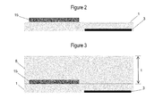
- Fig. 2 shows the last standard processing step of a 5-metal layer process following formation of the lower plate 3 within the support layer 1 and the bond pad 15 on the support layer 1 after top metal etch and strip.
- bond pad 15 could be formed on the support layer 1 using a process subsequent to the conventional process that resulted in the support layer 1.
- a layer of dielectric material 5 is deposited on the exposed portion of support layer 1 and bond pad 15 (by way of non-limiting example, this could be accomplished by deposition and/or subsequent oxidation steps).
- the layer of dielectric material 5 is then planarized to a desired thickness t.
- the layer of dielectric material 5 is a thick layer (e.g., an oxide) that is different from the standard oxide stack that would be formed if metal capacitors were to be formed within the support layer 1 in known fashion (e.g. Metal5 (or Metal6) to Metal1 capacitors).
- an additional thickness of dielectric material will be present between the lower and upper plates.
- a metal deposition step and a subsequent patterning step are performed to provide the upper plate 7 atop the dielectric layer 5.
- the lower and upper plates 3 and 7 and dielectric layer 5 together define a capacitor.
- a partial or full oxide etch could be performed above bond pad 15 to facilitate the later creation of opening 11 in a following step.
- a passivation layer 9 is formed on the upper plate 7 and exposed portions of the dielectric layer 5.
- the top surface of the passivation layer 9 may reflect the shape of the underlying top place 7, and so may not be even.
- openings 11 and 13 extending from the surface of the passivation layer 9 towards the bond pad 15 and upper plate 7, respectively, are formed. Openings 11 and 13 can be formed using known etching techniques, or any other suitable techniques now or hereafter known for the selective removal of material. The openings 11 and 13 can be formed sequentially or simultaneously. Formation of openings 11 and 13 results in exposure of portions of the bond pad 15 and upper plate 7. Electrical signal leads for device operation can then be attached to those exposed portions in any suitable manner now known or hereafter discovered.
- a photoexposure step and an additional etching step can be performed to reduce the thickness of portion of the passivation layer 9 covering the upper plate 7.
- the passivation layer 9 can be planarized to have a flat surface.
- the electrical properties of the capacitor 17 can be controlled by suitably choosing the thickness t of the dielectric layer 5, the material from which dielectric layer 5 is made, and the geometry of the lower and upper plates 3 and 7. For example, by increasing the thickness t of dielectric layer 5 (e.g., by increasing the thickness of the oxide layer during an oxidation step), the breakdown voltage of capacitor 17 can be increased.
- a high-voltage capacitor can be formed with a breakdown voltage which is greater than that possible were the capacitor to be formed using the Metal1 to Metal5 layers of the support layer 1.
Applications Claiming Priority (1)
| Application Number | Priority Date | Filing Date | Title |
|---|---|---|---|
| US13/648,882 US8957500B2 (en) | 2012-10-10 | 2012-10-10 | High-voltage integrated metal capacitor and fabrication method |
Publications (2)
| Publication Number | Publication Date |
|---|---|
| EP2720236A1 true EP2720236A1 (de) | 2014-04-16 |
| EP2720236B1 EP2720236B1 (de) | 2016-08-24 |
Family
ID=49150836
Family Applications (1)
| Application Number | Title | Priority Date | Filing Date |
|---|---|---|---|
| EP13183995.3A Active EP2720236B1 (de) | 2012-10-10 | 2013-09-11 | Hochspannungsvorrichtung mit integriertem Metallkondensator und Herstellungsverfahren |
Country Status (3)
| Country | Link |
|---|---|
| US (1) | US8957500B2 (de) |
| EP (1) | EP2720236B1 (de) |
| CN (1) | CN103730459B (de) |
Cited By (1)
| Publication number | Priority date | Publication date | Assignee | Title |
|---|---|---|---|---|
| US9640607B2 (en) | 2015-03-04 | 2017-05-02 | Tower Semiconductor Ltd. | Die including a high voltage capacitor |
Families Citing this family (8)
| Publication number | Priority date | Publication date | Assignee | Title |
|---|---|---|---|---|
| US9525021B2 (en) | 2014-11-06 | 2016-12-20 | Texas Instruments Incorporated | Methods and apparatus for high voltage integrated circuit capacitors |
| US9806148B2 (en) * | 2015-04-07 | 2017-10-31 | Texas Instruments Incorporated | Device isolator with reduced parasitic capacitance |
| CN107331661B (zh) * | 2017-06-23 | 2020-05-15 | 上海集成电路研发中心有限公司 | 一种cmos兼容的温度探测器及其制造方法 |
| US11049820B2 (en) * | 2018-07-30 | 2021-06-29 | Texas Instruments Incorporated | Crack suppression structure for HV isolation component |
| US11469169B2 (en) | 2020-11-23 | 2022-10-11 | Globalfoundries Singapore Pte. Ltd. | High voltage decoupling capacitor and integration methods |
| US11764273B2 (en) | 2021-06-01 | 2023-09-19 | Globalfoundries Singapore Pte. Ltd. | Semiconductor structures for galvanic isolation |
| US11626366B2 (en) * | 2021-06-22 | 2023-04-11 | Silicon Laboratories Inc. | Shielding using layers with staggered trenches |
| US11791379B2 (en) | 2021-12-16 | 2023-10-17 | Globalfoundries Singapore Pte Ltd | Galvanic isolation using isolation break between redistribution layer electrodes |
Citations (5)
| Publication number | Priority date | Publication date | Assignee | Title |
|---|---|---|---|---|
| US6372570B1 (en) * | 1998-07-21 | 2002-04-16 | Stmicroelectronics S. A. | Method of formation of a capacitor on an integrated circuit |
| US20020149086A1 (en) * | 2001-04-17 | 2002-10-17 | Casio Computer Co., Ltd. | Semiconductor device |
| US20060087029A1 (en) * | 2004-10-22 | 2006-04-27 | Fujitsu Limited | Semiconductor device and method of producing the same |
| US20080290444A1 (en) * | 2007-05-24 | 2008-11-27 | Philip John Crawley | Capacitor structure in a semiconductor device |
| US20100224960A1 (en) * | 2009-03-04 | 2010-09-09 | Kevin John Fischer | Embedded capacitor device and methods of fabrication |
Family Cites Families (7)
| Publication number | Priority date | Publication date | Assignee | Title |
|---|---|---|---|---|
| US20040027783A1 (en) * | 2002-08-08 | 2004-02-12 | United Microelectronics Corp. | Structure of metal-metal capacitor |
| KR100505658B1 (ko) * | 2002-12-11 | 2005-08-03 | 삼성전자주식회사 | MIM(Metal-Insulator-Metal)커패시터를 갖는 반도체 소자 |
| US7009406B2 (en) * | 2003-04-24 | 2006-03-07 | Delphi Technologies, Inc. | Arc fault detector and method |
| US20060186450A1 (en) * | 2005-02-24 | 2006-08-24 | Texas Instruments Inc. | Integrated high voltage capacitor and a method of manufacture therefor |
| US7723201B2 (en) * | 2006-01-09 | 2010-05-25 | International Business Machines Corporation | Structure and method for making on-chip capacitors with various capacitances |
| US8431463B2 (en) * | 2008-08-08 | 2013-04-30 | Texas Instruments Incorporated | Capacitor contact formed concurrently with bond pad metallization |
| US8803286B2 (en) * | 2010-11-05 | 2014-08-12 | Taiwan Semiconductor Manufacturing Company, Ltd. | Low cost metal-insulator-metal capacitors |
-
2012
- 2012-10-10 US US13/648,882 patent/US8957500B2/en active Active
-
2013
- 2013-09-11 EP EP13183995.3A patent/EP2720236B1/de active Active
- 2013-10-08 CN CN201310463826.7A patent/CN103730459B/zh active Active
Patent Citations (5)
| Publication number | Priority date | Publication date | Assignee | Title |
|---|---|---|---|---|
| US6372570B1 (en) * | 1998-07-21 | 2002-04-16 | Stmicroelectronics S. A. | Method of formation of a capacitor on an integrated circuit |
| US20020149086A1 (en) * | 2001-04-17 | 2002-10-17 | Casio Computer Co., Ltd. | Semiconductor device |
| US20060087029A1 (en) * | 2004-10-22 | 2006-04-27 | Fujitsu Limited | Semiconductor device and method of producing the same |
| US20080290444A1 (en) * | 2007-05-24 | 2008-11-27 | Philip John Crawley | Capacitor structure in a semiconductor device |
| US20100224960A1 (en) * | 2009-03-04 | 2010-09-09 | Kevin John Fischer | Embedded capacitor device and methods of fabrication |
Cited By (1)
| Publication number | Priority date | Publication date | Assignee | Title |
|---|---|---|---|---|
| US9640607B2 (en) | 2015-03-04 | 2017-05-02 | Tower Semiconductor Ltd. | Die including a high voltage capacitor |
Also Published As
| Publication number | Publication date |
|---|---|
| CN103730459B (zh) | 2016-09-14 |
| CN103730459A (zh) | 2014-04-16 |
| US8957500B2 (en) | 2015-02-17 |
| US20140097516A1 (en) | 2014-04-10 |
| EP2720236B1 (de) | 2016-08-24 |
Similar Documents
| Publication | Publication Date | Title |
|---|---|---|
| EP2720236B1 (de) | Hochspannungsvorrichtung mit integriertem Metallkondensator und Herstellungsverfahren | |
| US9711502B2 (en) | Double-side process silicon MOS and passive devices for RF front-end modules | |
| US10529796B2 (en) | Galvanic isolation device | |
| US8421238B2 (en) | Stacked semiconductor device with through via | |
| CN106611741B (zh) | 电介质堆叠,隔离设备并形成隔离设备的方法 | |
| US10930619B2 (en) | Multi-wafer bonding structure and bonding method | |
| EP2738828A2 (de) | MIM-Kondensator und Verfahren zu seiner Herstellung | |
| US10580581B2 (en) | High-density metal-insulator-metal capacitors | |
| US10199370B2 (en) | Electronic device with integrated galvanic isolation, and manufacturing method of the same | |
| EP2887387A1 (de) | Halbleitervorrichtung und zugehöriges Verfahren | |
| US11869988B2 (en) | Double-sided stacked DTC structure | |
| CN111295766A (zh) | 高电压隔离结构及方法 | |
| CN115053329A (zh) | 具有电过应力完整性的高电压隔离屏障 | |
| US20230230961A1 (en) | Ic package with multiple dies | |
| CN113161324A (zh) | 半导体装置及其制作方法 | |
| CN115715145A (zh) | 具有增强型底部板极的集成隔离电容器 | |
| CN111446365A (zh) | 一种隔离电容器和用于形成隔离电容的方法 | |
| US7485926B2 (en) | SOI contact structures | |
| US20220384585A1 (en) | Integrated electronic circuit including a field plate for the local reduction of the electric field and related manufacturing process | |
| CN117476613A (zh) | 一种芯片封装结构及其制造方法 | |
| CN116322295A (zh) | 容隔离器的制备方法、容隔离器及其应用 | |
| CN117153827A (zh) | 高压电容器及其制造方法,集成器件 | |
| CN117133758A (zh) | 高压电容器及其制造方法,集成器件 | |
| CN115966511A (zh) | 半导体器件及其制造方法 |
Legal Events
| Date | Code | Title | Description |
|---|---|---|---|
| PUAI | Public reference made under article 153(3) epc to a published international application that has entered the european phase |
Free format text: ORIGINAL CODE: 0009012 |
|
| AK | Designated contracting states |
Kind code of ref document: A1 Designated state(s): AL AT BE BG CH CY CZ DE DK EE ES FI FR GB GR HR HU IE IS IT LI LT LU LV MC MK MT NL NO PL PT RO RS SE SI SK SM TR |
|
| AX | Request for extension of the european patent |
Extension state: BA ME |
|
| 17P | Request for examination filed |
Effective date: 20140326 |
|
| RBV | Designated contracting states (corrected) |
Designated state(s): AL AT BE BG CH CY CZ DE DK EE ES FI FR GB GR HR HU IE IS IT LI LT LU LV MC MK MT NL NO PL PT RO RS SE SI SK SM TR |
|
| GRAP | Despatch of communication of intention to grant a patent |
Free format text: ORIGINAL CODE: EPIDOSNIGR1 |
|
| INTG | Intention to grant announced |
Effective date: 20160307 |
|
| GRAS | Grant fee paid |
Free format text: ORIGINAL CODE: EPIDOSNIGR3 |
|
| GRAA | (expected) grant |
Free format text: ORIGINAL CODE: 0009210 |
|
| AK | Designated contracting states |
Kind code of ref document: B1 Designated state(s): AL AT BE BG CH CY CZ DE DK EE ES FI FR GB GR HR HU IE IS IT LI LT LU LV MC MK MT NL NO PL PT RO RS SE SI SK SM TR |
|
| REG | Reference to a national code |
Ref country code: GB Ref legal event code: FG4D |
|
| REG | Reference to a national code |
Ref country code: CH Ref legal event code: EP |
|
| REG | Reference to a national code |
Ref country code: AT Ref legal event code: REF Ref document number: 823723 Country of ref document: AT Kind code of ref document: T Effective date: 20160915 |
|
| REG | Reference to a national code |
Ref country code: IE Ref legal event code: FG4D Ref country code: FR Ref legal event code: PLFP Year of fee payment: 4 |
|
| REG | Reference to a national code |
Ref country code: DE Ref legal event code: R096 Ref document number: 602013010550 Country of ref document: DE |
|
| REG | Reference to a national code |
Ref country code: LT Ref legal event code: MG4D |
|
| REG | Reference to a national code |
Ref country code: NL Ref legal event code: MP Effective date: 20160824 |
|
| REG | Reference to a national code |
Ref country code: AT Ref legal event code: MK05 Ref document number: 823723 Country of ref document: AT Kind code of ref document: T Effective date: 20160824 |
|
| PG25 | Lapsed in a contracting state [announced via postgrant information from national office to epo] |
Ref country code: FI Free format text: LAPSE BECAUSE OF FAILURE TO SUBMIT A TRANSLATION OF THE DESCRIPTION OR TO PAY THE FEE WITHIN THE PRESCRIBED TIME-LIMIT Effective date: 20160824 Ref country code: LT Free format text: LAPSE BECAUSE OF FAILURE TO SUBMIT A TRANSLATION OF THE DESCRIPTION OR TO PAY THE FEE WITHIN THE PRESCRIBED TIME-LIMIT Effective date: 20160824 Ref country code: NO Free format text: LAPSE BECAUSE OF FAILURE TO SUBMIT A TRANSLATION OF THE DESCRIPTION OR TO PAY THE FEE WITHIN THE PRESCRIBED TIME-LIMIT Effective date: 20161124 Ref country code: RS Free format text: LAPSE BECAUSE OF FAILURE TO SUBMIT A TRANSLATION OF THE DESCRIPTION OR TO PAY THE FEE WITHIN THE PRESCRIBED TIME-LIMIT Effective date: 20160824 Ref country code: HR Free format text: LAPSE BECAUSE OF FAILURE TO SUBMIT A TRANSLATION OF THE DESCRIPTION OR TO PAY THE FEE WITHIN THE PRESCRIBED TIME-LIMIT Effective date: 20160824 Ref country code: IT Free format text: LAPSE BECAUSE OF FAILURE TO SUBMIT A TRANSLATION OF THE DESCRIPTION OR TO PAY THE FEE WITHIN THE PRESCRIBED TIME-LIMIT Effective date: 20160824 Ref country code: NL Free format text: LAPSE BECAUSE OF FAILURE TO SUBMIT A TRANSLATION OF THE DESCRIPTION OR TO PAY THE FEE WITHIN THE PRESCRIBED TIME-LIMIT Effective date: 20160824 |
|
| PG25 | Lapsed in a contracting state [announced via postgrant information from national office to epo] |
Ref country code: GR Free format text: LAPSE BECAUSE OF FAILURE TO SUBMIT A TRANSLATION OF THE DESCRIPTION OR TO PAY THE FEE WITHIN THE PRESCRIBED TIME-LIMIT Effective date: 20161125 Ref country code: ES Free format text: LAPSE BECAUSE OF FAILURE TO SUBMIT A TRANSLATION OF THE DESCRIPTION OR TO PAY THE FEE WITHIN THE PRESCRIBED TIME-LIMIT Effective date: 20160824 Ref country code: SE Free format text: LAPSE BECAUSE OF FAILURE TO SUBMIT A TRANSLATION OF THE DESCRIPTION OR TO PAY THE FEE WITHIN THE PRESCRIBED TIME-LIMIT Effective date: 20160824 Ref country code: LV Free format text: LAPSE BECAUSE OF FAILURE TO SUBMIT A TRANSLATION OF THE DESCRIPTION OR TO PAY THE FEE WITHIN THE PRESCRIBED TIME-LIMIT Effective date: 20160824 Ref country code: PT Free format text: LAPSE BECAUSE OF FAILURE TO SUBMIT A TRANSLATION OF THE DESCRIPTION OR TO PAY THE FEE WITHIN THE PRESCRIBED TIME-LIMIT Effective date: 20161226 Ref country code: BE Free format text: LAPSE BECAUSE OF NON-PAYMENT OF DUE FEES Effective date: 20160930 Ref country code: AT Free format text: LAPSE BECAUSE OF FAILURE TO SUBMIT A TRANSLATION OF THE DESCRIPTION OR TO PAY THE FEE WITHIN THE PRESCRIBED TIME-LIMIT Effective date: 20160824 |
|
| PG25 | Lapsed in a contracting state [announced via postgrant information from national office to epo] |
Ref country code: EE Free format text: LAPSE BECAUSE OF FAILURE TO SUBMIT A TRANSLATION OF THE DESCRIPTION OR TO PAY THE FEE WITHIN THE PRESCRIBED TIME-LIMIT Effective date: 20160824 Ref country code: RO Free format text: LAPSE BECAUSE OF FAILURE TO SUBMIT A TRANSLATION OF THE DESCRIPTION OR TO PAY THE FEE WITHIN THE PRESCRIBED TIME-LIMIT Effective date: 20160824 |
|
| REG | Reference to a national code |
Ref country code: CH Ref legal event code: PL |
|
| REG | Reference to a national code |
Ref country code: DE Ref legal event code: R097 Ref document number: 602013010550 Country of ref document: DE |
|
| PG25 | Lapsed in a contracting state [announced via postgrant information from national office to epo] |
Ref country code: PL Free format text: LAPSE BECAUSE OF FAILURE TO SUBMIT A TRANSLATION OF THE DESCRIPTION OR TO PAY THE FEE WITHIN THE PRESCRIBED TIME-LIMIT Effective date: 20160824 Ref country code: CZ Free format text: LAPSE BECAUSE OF FAILURE TO SUBMIT A TRANSLATION OF THE DESCRIPTION OR TO PAY THE FEE WITHIN THE PRESCRIBED TIME-LIMIT Effective date: 20160824 Ref country code: SM Free format text: LAPSE BECAUSE OF FAILURE TO SUBMIT A TRANSLATION OF THE DESCRIPTION OR TO PAY THE FEE WITHIN THE PRESCRIBED TIME-LIMIT Effective date: 20160824 Ref country code: BG Free format text: LAPSE BECAUSE OF FAILURE TO SUBMIT A TRANSLATION OF THE DESCRIPTION OR TO PAY THE FEE WITHIN THE PRESCRIBED TIME-LIMIT Effective date: 20161124 Ref country code: SK Free format text: LAPSE BECAUSE OF FAILURE TO SUBMIT A TRANSLATION OF THE DESCRIPTION OR TO PAY THE FEE WITHIN THE PRESCRIBED TIME-LIMIT Effective date: 20160824 Ref country code: DK Free format text: LAPSE BECAUSE OF FAILURE TO SUBMIT A TRANSLATION OF THE DESCRIPTION OR TO PAY THE FEE WITHIN THE PRESCRIBED TIME-LIMIT Effective date: 20160824 Ref country code: BE Free format text: LAPSE BECAUSE OF FAILURE TO SUBMIT A TRANSLATION OF THE DESCRIPTION OR TO PAY THE FEE WITHIN THE PRESCRIBED TIME-LIMIT Effective date: 20160824 |
|
| REG | Reference to a national code |
Ref country code: IE Ref legal event code: MM4A |
|
| PG25 | Lapsed in a contracting state [announced via postgrant information from national office to epo] |
Ref country code: MC Free format text: LAPSE BECAUSE OF FAILURE TO SUBMIT A TRANSLATION OF THE DESCRIPTION OR TO PAY THE FEE WITHIN THE PRESCRIBED TIME-LIMIT Effective date: 20160824 |
|
| PLBE | No opposition filed within time limit |
Free format text: ORIGINAL CODE: 0009261 |
|
| STAA | Information on the status of an ep patent application or granted ep patent |
Free format text: STATUS: NO OPPOSITION FILED WITHIN TIME LIMIT |
|
| PG25 | Lapsed in a contracting state [announced via postgrant information from national office to epo] |
Ref country code: CH Free format text: LAPSE BECAUSE OF NON-PAYMENT OF DUE FEES Effective date: 20160930 Ref country code: LI Free format text: LAPSE BECAUSE OF NON-PAYMENT OF DUE FEES Effective date: 20160930 Ref country code: IE Free format text: LAPSE BECAUSE OF NON-PAYMENT OF DUE FEES Effective date: 20160911 |
|
| 26N | No opposition filed |
Effective date: 20170526 |
|
| REG | Reference to a national code |
Ref country code: FR Ref legal event code: PLFP Year of fee payment: 5 |
|
| PG25 | Lapsed in a contracting state [announced via postgrant information from national office to epo] |
Ref country code: LU Free format text: LAPSE BECAUSE OF NON-PAYMENT OF DUE FEES Effective date: 20160911 Ref country code: SI Free format text: LAPSE BECAUSE OF FAILURE TO SUBMIT A TRANSLATION OF THE DESCRIPTION OR TO PAY THE FEE WITHIN THE PRESCRIBED TIME-LIMIT Effective date: 20160824 |
|
| PG25 | Lapsed in a contracting state [announced via postgrant information from national office to epo] |
Ref country code: CY Free format text: LAPSE BECAUSE OF FAILURE TO SUBMIT A TRANSLATION OF THE DESCRIPTION OR TO PAY THE FEE WITHIN THE PRESCRIBED TIME-LIMIT Effective date: 20160824 Ref country code: HU Free format text: LAPSE BECAUSE OF FAILURE TO SUBMIT A TRANSLATION OF THE DESCRIPTION OR TO PAY THE FEE WITHIN THE PRESCRIBED TIME-LIMIT; INVALID AB INITIO Effective date: 20130911 |
|
| PG25 | Lapsed in a contracting state [announced via postgrant information from national office to epo] |
Ref country code: MT Free format text: LAPSE BECAUSE OF NON-PAYMENT OF DUE FEES Effective date: 20160930 Ref country code: IS Free format text: LAPSE BECAUSE OF FAILURE TO SUBMIT A TRANSLATION OF THE DESCRIPTION OR TO PAY THE FEE WITHIN THE PRESCRIBED TIME-LIMIT Effective date: 20160824 Ref country code: MK Free format text: LAPSE BECAUSE OF FAILURE TO SUBMIT A TRANSLATION OF THE DESCRIPTION OR TO PAY THE FEE WITHIN THE PRESCRIBED TIME-LIMIT Effective date: 20160824 |
|
| REG | Reference to a national code |
Ref country code: FR Ref legal event code: PLFP Year of fee payment: 6 |
|
| PG25 | Lapsed in a contracting state [announced via postgrant information from national office to epo] |
Ref country code: TR Free format text: LAPSE BECAUSE OF FAILURE TO SUBMIT A TRANSLATION OF THE DESCRIPTION OR TO PAY THE FEE WITHIN THE PRESCRIBED TIME-LIMIT Effective date: 20160824 Ref country code: AL Free format text: LAPSE BECAUSE OF FAILURE TO SUBMIT A TRANSLATION OF THE DESCRIPTION OR TO PAY THE FEE WITHIN THE PRESCRIBED TIME-LIMIT Effective date: 20160824 |
|
| P01 | Opt-out of the competence of the unified patent court (upc) registered |
Effective date: 20230725 |
|
| PGFP | Annual fee paid to national office [announced via postgrant information from national office to epo] |
Ref country code: GB Payment date: 20230823 Year of fee payment: 11 |
|
| PGFP | Annual fee paid to national office [announced via postgrant information from national office to epo] |
Ref country code: FR Payment date: 20230822 Year of fee payment: 11 Ref country code: DE Payment date: 20230822 Year of fee payment: 11 |