EP2719185B1 - Projection system - Google Patents
Projection system Download PDFInfo
- Publication number
- EP2719185B1 EP2719185B1 EP12740240.2A EP12740240A EP2719185B1 EP 2719185 B1 EP2719185 B1 EP 2719185B1 EP 12740240 A EP12740240 A EP 12740240A EP 2719185 B1 EP2719185 B1 EP 2719185B1
- Authority
- EP
- European Patent Office
- Prior art keywords
- screen
- projectors
- digital
- digital projectors
- auditorium
- Prior art date
- Legal status (The legal status is an assumption and is not a legal conclusion. Google has not performed a legal analysis and makes no representation as to the accuracy of the status listed.)
- Active
Links
Images


Classifications
-
- G—PHYSICS
- G03—PHOTOGRAPHY; CINEMATOGRAPHY; ANALOGOUS TECHNIQUES USING WAVES OTHER THAN OPTICAL WAVES; ELECTROGRAPHY; HOLOGRAPHY
- G03B—APPARATUS OR ARRANGEMENTS FOR TAKING PHOTOGRAPHS OR FOR PROJECTING OR VIEWING THEM; APPARATUS OR ARRANGEMENTS EMPLOYING ANALOGOUS TECHNIQUES USING WAVES OTHER THAN OPTICAL WAVES; ACCESSORIES THEREFOR
- G03B21/00—Projectors or projection-type viewers; Accessories therefor
- G03B21/14—Details
- G03B21/147—Optical correction of image distortions, e.g. keystone
-
- G—PHYSICS
- G03—PHOTOGRAPHY; CINEMATOGRAPHY; ANALOGOUS TECHNIQUES USING WAVES OTHER THAN OPTICAL WAVES; ELECTROGRAPHY; HOLOGRAPHY
- G03B—APPARATUS OR ARRANGEMENTS FOR TAKING PHOTOGRAPHS OR FOR PROJECTING OR VIEWING THEM; APPARATUS OR ARRANGEMENTS EMPLOYING ANALOGOUS TECHNIQUES USING WAVES OTHER THAN OPTICAL WAVES; ACCESSORIES THEREFOR
- G03B21/00—Projectors or projection-type viewers; Accessories therefor
- G03B21/14—Details
- G03B21/26—Projecting separately subsidiary matter simultaneously with main image
-
- G—PHYSICS
- G03—PHOTOGRAPHY; CINEMATOGRAPHY; ANALOGOUS TECHNIQUES USING WAVES OTHER THAN OPTICAL WAVES; ELECTROGRAPHY; HOLOGRAPHY
- G03B—APPARATUS OR ARRANGEMENTS FOR TAKING PHOTOGRAPHS OR FOR PROJECTING OR VIEWING THEM; APPARATUS OR ARRANGEMENTS EMPLOYING ANALOGOUS TECHNIQUES USING WAVES OTHER THAN OPTICAL WAVES; ACCESSORIES THEREFOR
- G03B35/00—Stereoscopic photography
- G03B35/18—Stereoscopic photography by simultaneous viewing
- G03B35/20—Stereoscopic photography by simultaneous viewing using two or more projectors
-
- G—PHYSICS
- G03—PHOTOGRAPHY; CINEMATOGRAPHY; ANALOGOUS TECHNIQUES USING WAVES OTHER THAN OPTICAL WAVES; ELECTROGRAPHY; HOLOGRAPHY
- G03B—APPARATUS OR ARRANGEMENTS FOR TAKING PHOTOGRAPHS OR FOR PROJECTING OR VIEWING THEM; APPARATUS OR ARRANGEMENTS EMPLOYING ANALOGOUS TECHNIQUES USING WAVES OTHER THAN OPTICAL WAVES; ACCESSORIES THEREFOR
- G03B37/00—Panoramic or wide-screen photography; Photographing extended surfaces, e.g. for surveying; Photographing internal surfaces, e.g. of pipe
- G03B37/04—Panoramic or wide-screen photography; Photographing extended surfaces, e.g. for surveying; Photographing internal surfaces, e.g. of pipe with cameras or projectors providing touching or overlapping fields of view
-
- H—ELECTRICITY
- H04—ELECTRIC COMMUNICATION TECHNIQUE
- H04N—PICTORIAL COMMUNICATION, e.g. TELEVISION
- H04N13/00—Stereoscopic video systems; Multi-view video systems; Details thereof
- H04N13/30—Image reproducers
- H04N13/332—Displays for viewing with the aid of special glasses or head-mounted displays [HMD]
- H04N13/337—Displays for viewing with the aid of special glasses or head-mounted displays [HMD] using polarisation multiplexing
-
- H—ELECTRICITY
- H04—ELECTRIC COMMUNICATION TECHNIQUE
- H04N—PICTORIAL COMMUNICATION, e.g. TELEVISION
- H04N13/00—Stereoscopic video systems; Multi-view video systems; Details thereof
- H04N13/30—Image reproducers
- H04N13/363—Image reproducers using image projection screens
-
- H—ELECTRICITY
- H04—ELECTRIC COMMUNICATION TECHNIQUE
- H04N—PICTORIAL COMMUNICATION, e.g. TELEVISION
- H04N9/00—Details of colour television systems
- H04N9/12—Picture reproducers
- H04N9/31—Projection devices for colour picture display, e.g. using electronic spatial light modulators [ESLM]
- H04N9/3141—Constructional details thereof
- H04N9/3147—Multi-projection systems
-
- H—ELECTRICITY
- H04—ELECTRIC COMMUNICATION TECHNIQUE
- H04N—PICTORIAL COMMUNICATION, e.g. TELEVISION
- H04N9/00—Details of colour television systems
- H04N9/12—Picture reproducers
- H04N9/31—Projection devices for colour picture display, e.g. using electronic spatial light modulators [ESLM]
- H04N9/3179—Video signal processing therefor
- H04N9/3185—Geometric adjustment, e.g. keystone or convergence
Definitions
- the present invention relates to screens for displays of images and more particularly to screens used for the display and viewing of motion pictures including 3D cinema.
- Screens for viewing cinema and other images are available in a wide range of structures and properties.
- the directivity of a screen relates to the amount or angle of specular reflection of light from the screen.
- the directivity of the viewing screen often has broad Gaussian like properties which reduce the apparent brightness of the screen (to an individual viewer), but maintain a very consistent relative image brightness across the screen at various angles such that image quality is consistent between the front, back, middle, and sides of the typical viewing audience.
- screens with high directivity are utilized because they have the capability of preserving polarization when light is reflected off the screen. Changes in polarization will typically cause crosstalk between the separately polarized left and right eye channels and thereby erode or even destroy the "3D" effect.
- high directivity screens also produce undesirable effects such as hot spots and less uniform relative illumination across the screen. These problems can be exasperated at oblique viewing angles such that some viewing/seating positions in the theater may be less desirable or undesirable.
- Spectral separation provides separation at the projector by filtering the left and right eye spectrally.
- the system differs from anaglyph in that the filters for the left and right eye each pass a portion of the red, green, and blue spectrum, providing for a full color image, and further differs from polarization based systems in that highly directive (or polarization preserving) screens are not needed, but can be utilized if the expense of greater hot spotting is deemed acceptable.
- the band pass spectrum of the left eye filter is complementary to the band pass spectrum of the right eye filter.
- the eyewear consists of filters with the same general spectral characteristics as are used in the projector.
- All of the above methods for providing left/right eye separation for a 3D Stereoscopic presentation can be used with either two projectors (e.g., one for the left eye and one for the right eye), or may be used with a single D-Cinema projector system.
- the projection filter e.g. spectral filter or polarization control
- the projection filter may be static or dynamic and may be located in front of the projection lens or inside the projector.
- the projectors are placed in close proximity to enhance alignment and uniformity of the projected images.
- 009219381 A1 discloses a 3D projection system using 3 projectors itioned behind the audience.
- US 2006/033890 A1 discloses a display apparatus that displays one image plane using plural projection type image display devices.
- the plural projection type image display devices that together form the display apparatus can be disposed in such a manner that at most one projection type image display device among the plural projection type image display devices forms a projection region of an original shape of projection on a screen.
- US 2007/091118 A1 discloses a display system including a display device and a data processing module.
- the display device is configured to display an image and has a processing profile associated therewith.
- the data processing module is remote from and operatively coupled to the display device and is configured to receive input image data for the image to be displayed and generate processed image data from the input image data based on the processing profile of the display device.
- the present inventor has realized the need to reduce hot spotting, particularly with the use of highly directive screens so that they may be more successfully implemented in 2D and 3D displays such as cinema and home theater applications.
- One result of the invention is the provision of higher reflectivity/directivity to a screen being utilized, increasing overall brightness but maintaining uniformity of the relative brightness across the screen.
- the present invention includes the use of multiple projectors located at the edges of an auditorium (or widely spaced) combined with screens having controlled (e.g., non-Gaussian) directivity to allow the use of screen gains in excess of 3 while maintaining reasonable uniformity across the screen when viewed from various seating positions in an auditorium.
- the uniformity is improved to the extent that in some embodiments retro reflection screens may also be used.
- Using this method also reduces crosstalk, particularly at the edges of the screen, for polarization systems (e.g., polarization based 3D cinema). Similar advantages may be obtained with a single projector by having a screen with gain characteristics that vary smoothly with screen position. This type of a screen could be constructed, for example, by smoothly varying the gain across the screen.
- Fig. 1A there is illustrated a diagram of an arrangement of a cinema theater 100 having a seating area and dimensions of approximately 50 ft. x 70 ft. and a 40 ft. screen 110.
- the dimensions will be utilized in Figs. 1D-2C to describe viewing angles and reflection quality using flat normal (e.g., Gaussian like reflecting properties), retro reflective (retro) flat, and curved normal screens for both worst case (front row end) and mid edge seating positions.
- the dimensions will again be utilized in Figs. 3A-4C to describe viewing angles and reflection according to the invention quality using flat normal, normal curved, and retro-reflective flat screens in both worst case and mid edge seats.
- the invention may utilize any of the symmetrically located projector pairs (any of P3/P5, P2/P6, P1/P7) (note: symmetry is a convenience and beneficial, but not a requirement of the invention) and an optional central projector P4.
- the locations are exemplary, and any number of placements for similar or additional effect may be utilized (including ceiling and floor mounted projectors, or projectors located closer to the viewing screen).
- Projectors P3 and P4 are, for example, separated as far apart as practical which includes having a clear shot to illuminate screen 110. In a 50' wide auditorium, this corresponds to a 25 foot distance from the projector to auditorium center.
- Projectors P2 and P6 are, for example, mounted on opposite side walls of the theater and forward of the back wall by 1/10 th a distance to the screen (e.g., approximately 7 feet).
- Projectors P1 and P7 are, for example, mounted on opposite side walls 1/5 th a distance to the screen (e.g., approximately 15 feet forward of the back wall). Other distances forward of the back wall may be utilized.
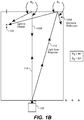
- Fig. 1B is a diagram showing reflections in a cinema theater with a flat normal screen for a worst case viewer 120.
- Light from projector 125 strikes across the screen (e.g., light paths 115 and 116) and reflected to the worst case viewer 120, most notably at a far end of the screen (angle 01, the angle between specular reflection 125A and the viewer) and at screen center (angle ⁇ 2, the angle between specular reflection 125B, along the incident light path, and the viewer).
- ⁇ 1 approximately 90 degrees
- ⁇ 2 approximately 63 degrees.
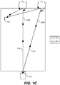
- Fig. 1C is a diagram showing reflections in a cinema theater with a retro reflecting screen for the worst case viewer 120.
- ⁇ 1 the angle between specular reflection 126A and the viewer
- ⁇ 2 the angle between specular reflection 126B and the viewer
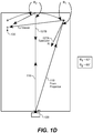
- Fig. 1D is a diagram showing reflections in a cinema theater with a curved normal screen for a worst case viewer.
- the curved screen has, for example, a center of radius of curvature close to the projector location.
- ⁇ 1 the angle between specular reflection 127A, slightly inward from the incident light path, and the viewer
- ⁇ 2 the angle between specular reflection 127B, along incident light path, and the viewer
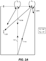
- Fig. 2A is a diagram showing reflections in a cinema theater with a flat normal screen for a mid edge viewer 135.
- Light from projector 125 strikes across the screen and is reflected to the mid edge viewer 220, most notably at a far end of the screen (angle 01, the angle between specular reflection 225A and the viewer) and at screen center (angle ⁇ 2, the angle between specular reflection 225B, along the incident light path, and the viewer).
- ⁇ 1 approximately 65 degrees
- ⁇ 2 approximately 30 degrees.
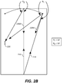
- Fig. 2B is a diagram showing reflections in a cinema theater with a curved normal screen for the mid edge viewer 220.
- ⁇ 1 the angle between specular reflection 226A, slightly inward from the incident light path, and the viewer
- ⁇ 2 the angle between specular reflection 226B, along incident light path, and the viewer
- Fig. 2C is a diagram showing reflections in a cinema theater with a flat retro reflecting screen for a mid edge viewer.
- ⁇ 1 the angle between specular reflection 227A, along the light incident path, and the viewer
- ⁇ 2 the angle between specular reflection 227B, along the incident light path, and the viewer
- Fig. 3A is a diagram showing reflections in a cinema theater using widely spaced dual projectors P1 and P2 with a flat normal screen for a worst case viewer.
- Light from projector P2 strikes across the screen and reflected to the worst case viewer 320, most notably at a far end of the screen (angle 01, the angle between specular reflection 325A, along the light incident path, and the viewer) and at screen center (angle ⁇ 2, the angle between specular reflection 325B and the viewer).
- ⁇ 1 approximately 75 degrees
- ⁇ 2 approximately 47 degrees.
- the viewer would also receive supplemental illumination from the other projector (e.g., 301).
- ⁇ 1 is improved over a single projector by approximately 15 degrees
- ⁇ 2 is improved by approximately 16 degrees.
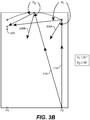
- Fig. 3B is a diagram showing reflections in a cinema theater using widely spaced dual projectors with a curved normal screen for a worst case viewer.
- ⁇ 1 the angle between specular reflection 326A, inward from the incident light path, and the viewer
- ⁇ 2 the angle between specular reflection 326B, outward of the incident light path, and the viewer
- ⁇ 1 is improved over a single projector by approximately 11 degrees
- ⁇ 2 is improved by approximately 15 degrees.
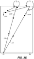
- Fig. 3C is a diagram showing reflections in a cinema theater using widely spaced dual projectors with a retro reflecting screen for a worst case viewer.
- ⁇ 1 the angle between specular reflection 327A, along the light incident path, and the viewer
- ⁇ 2 the angle between specular reflection 327B, along the incident light path, and the viewer
- a retro-reflecting screen has approximately the same qualities as a curved normal screen.
- a worst case viewer viewing a retro-reflecting screen with 2 widely spaced projectors improves over a curved normal screen with one projector such that ⁇ 1 is improved by approximately 14 degrees, and ⁇ 2 is improved by approximately 17 degrees.
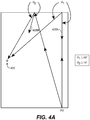
- Fig. 4A is a diagram showing reflections in a cinema theater using widely spaced dual projectors with a flat normal screen for a mid edge viewer.
- Light from projector 402 strikes across the screen and reflected to the mid edge viewer 420, most notably at a far end of the screen (angle ⁇ 1, the angle between specular reflection 425A and the viewer) and at screen center (angle ⁇ 2, the angle between specular reflection 425B and the viewer).
- ⁇ 1 approximately 49 degrees
- ⁇ 2 approximately 14 degrees.
- the viewer would also receive supplemental illumination from the other projector (e.g., 401) .
- Fig. 4B is a diagram showing reflections in a cinema theater using widely spaced dual projectors with a curved normal screen for the mid edge viewer 420.
- ⁇ 1 the angle between specular reflection 426A, inward from the incident light path, and the viewer
- ⁇ 2 the angle between specular reflection 426B, outward of the incident light path, and the viewer
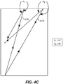
- Fig. 4C is a diagram showing reflections in a cinema theater using widely spaced dual projectors with a retro reflecting screen for a mid edge viewer.
- ⁇ 1 the angle between specular reflection 417A, along the light incident path, and the viewer
- ⁇ 2 the angle between specular reflection 417B, along the incident light path, and the viewer
- a retro-reflecting screen with dual projectors is improved over a curved normal screen with a center projector such that ⁇ 1 improves by approximately 13 degrees (32 degrees - 19 degrees), and ⁇ 2 is improved by approximately 16 degrees (30 degrees - 14 degrees).
- FIG. 1 A projector spacing equivalent to a fractional portion of the width of the viewing screen may be utilized.
- projector spacing may be any of 1/4, 1/3, 1/2, 2/3, and 3/4 a width (or close approximation thereof) of the viewing screen. The best advantage for uniformity and reduced hot spotting occurs with wider spacings.
- the projectors are spaced apart by more than 1 ⁇ 4 the width of the viewing screen. Preferably, the projectors are spaced as far apart as practical.
- the spacing may depend on structural factors of the theater or projection booth in which the projectors are installed.
- the projectors are spaced such that the projectors are adjacent to opposite walls.
- the projectors are spaced at a full width of the viewing screen. In other embodiments, the projectors are both placed apart further than a width of the viewing screen.
- the invention may be practiced with more than 2 projectors.
- 2 projectors at opposite side walls e.g., at a back of a theater or forward of the back wall
- the center projector may project from the back wall (e.g., a traditional theater projection location) or from a ceiling mounted location.
- An array of projectors may be utilized, for example, projectors at opposite side wall locations (e.g.
- ceiling mounted locations e.g., a centrally located ceiling, and/or widely spaced ceiling mounted projectors
- seating area floor mounted projector or projectors e.g., any number of back wall projectors (e.g., widely spaced dual projectors, and/or a center projector, and/or quad projectors).
- the projectors are spaced apart to a maximum amount corresponding to the projectors' (or server's) ability to correct for the trapezoidal effect and maintain a desired resolution of the projected images (and may also be limited by the physical dimensions of the theater).
- the desired resolution is an HD resolution.
- the desired resolution, brightness, contrast, and color gamut is within Visual Dynamic Range (VDR) specifications. Alternatively, the specifications may exceed the normal range of human vision.
- the characteristics of the display are designed to meet a 500 nit brightness level, HD or better resolution, 2000:1 in scene contrast ratio, 10,000:1 dynamic contrast ratio, and a color gamut above the Digital Cinema Initiative (DCI) specification for P3 (a.k.a., DCI-P3).
- the desired resolution is a native resolution of the motion pictures provided to the cinema and/or projectors.
- a first of the dual projectors is configured to alternately project a first channel of a 3D image and then a second channel.
- the second projector also being configured to alternately project the first and second channels.
- the projectors may be inversely synchronized such that when the first projector is projecting the second channel, the second projector is projecting the first channel and visa versa.
- the projections are made onto a screen having high directivity (e.g., greater than 2.0). In various embodiments, the directivity is 3.0 or greater.
- the screen is a retro-reflective screen. In one embodiment, more than 3 projectors are utilized (e.g., 4 projectors that may include 2 projectors projecting from side wall areas of the theater and 2 projectors projecting from a back wall areas of the theater).
- the invention comprises a projection system having a first projector and a second projector spaced apart more than one projector width (e.g., 3 or more projector widths, or spaced apart more than 10 feet), wherein the first projector is configured to project a first direction trapezoidal corrected image and the second projector is configured to project a second (and opposite) direction trapezoidal corrected image.
- the first projector may be closer to a first side wall of a theater than a center of the theater and the second projector may be closer to an opposite side wall of the theater than the center (e.g., the first projector is adjacent to the first side wall and the second projector is adjacent to the opposite side wall).
- the projectors may be positioned at or past the side walls as the lens of each projector only needs a clear path to the screen. Both projectors may also be along the back wall of the theater (e.g., in the projection booth) or at a predetermined location between the screen and the back wall.
- Space between the projectors and any closest wall may comprise solely an operation space for maintaining the projectors.
- the trapezoidal corrections may comprise corrections for image registration errors caused by more than 5 feet of separation between the projectors.
- the trapezoidal corrections may comprise corrections for image registration errors caused by placement of the projectors at opposite side walls of the theater and, for example, more than 5 feet of separation.
- a trapezoidal correction device may be configured to prepare image data and/or cause an image to be modulated that is inversely proportional to trapezoidal distortions that would occur on a viewing screen without the correction due to the projectors being spaced apart more than 1/4 a width of the screen.
- the first and second projectors may be configured to project 3D images.
- the 3D images may comprise left and right channel images separated by polarization.
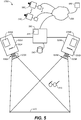
- FIG. 5 is a diagram illustrating widely spaced dual projectors according to embodiments of the present invention.
- a projection system 500 includes a first digital cinema projector 505A and a second digital cinema projector 505B that project 2D or 3D images (e.g. a left channel image and a right channel image). As shown, the projectors are angled so that they illuminate the screen.
- the projectors may comprise, for example, standard bulb illuminated projectors or laser based projectors.
- the 3D embodiments may be, for example, spectrally separated or polarization based systems.
- the projectors may then project through projection filters or polarization converting screens (e.g., filters 530A/B, or z-type screens 525A/B) onto a screen 510 for viewing with glasses 515.
- the filters/screens alternate polarization orientation or spectral properties in time with alternating frames from opposite channels projected from the projectors.
- Glasses 515 include, for example, spectrally separated filters disposed as coatings on each lens of the glasses such that the right lens comprises a filter that matches or encompasses the passbands of the right channel filter and the left lens comprises a filter that matches or encompasses passbands of the left channel filter (each of the left and right channel images are intended to be viewed by a viewer's corresponding left or right eye through the corresponding left or right eye lens/filter of the glasses).
- the glasses 515, and system 500 may, for example, include any of the features, systems, or devices described in Richards et al., a U.S. Patent entitled METHOD AND SYSTEM FOR SHAPED GLASSES AND VIEWING 3D IMAGES, Patent No.
- glasses 515 may also be polarization based (e.g., left and right circularly polarized lenses) matching polarized projections of each corresponding channel.
- polarization based e.g., left and right circularly polarized lenses
- the projectors 505A/B receive image data for projection, for example, from a server 580.
- Content e.g., 3D content
- content may be transmitted to projectors 505A/B over a secure link of network 555 from, for example, an image warehouse or studio 550.
- Multiple other projectors e.g., at theaters around the globe, 560 1 ..560n
- the server 580 may include a color correction module 1775.
- the server 580 may include ghost busting algorithms to be applied to image content to correct, for example, crosstalk issues or other artifacts.
- the server 580 includes image correction capabilities to account for the trapezoidal effect from the spaced apart projectors.
- the trapezoidal effect correction corrects for registration of the two images (to cause the image from projector 505A to be registered with the image projected from projector 505B).
- the correction may be performed by shifting pixel data on modulators of the projectors such that corresponding pixels in an image being projected by each projector illuminate a same pixel area of the screen 510. Such adjustments are performed at the server 580 or by programming/electronics resident in each projector.
- the image data may be pre-shifted before delivery to the server/projectors and/or theaters.
- the screen 510 is a high directivity screen comprising, for example, a directivity rating greater than 2. In one embodiment, the screen 510 has a directivity rating of 2.4. In yet another embodiment, the screen 510 has a directivity rating of 3.0. In still yet another embodiment, the screen 510 is retro-reflective.
- FIG. 6 is a performance graph 600 of left and center isle seating positions in a theater using a single projector and a 1.8 gain screen.
- a gain of left isle seating (encompassing the worst case seating position in the first row) comprises gain curves that equate to increasing rows from a front row 610 1 to a back row 610 n . The curves do not represent every row but show approximately equidistant increments from the first row to the back row.
- a center isle position is shown from a front row 620 1 to a back row 620 n .
- Fig. 7 is a performance graph 700 of left and center isle seating positions in a theater using a single projector and a 2.2 gain screen.
- Fig. 7 shows gain curves for increasing distance from a front row to a back row for the left isle (curves 710 1 to 710 n ) and a center isle (curves 720 1 to 720 n ).
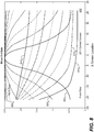
- Fig. 8 is a performance graph 800 of left and center isle seating positions in a theater using a single projector and a 2.4 gain screen.
- Fig. 8 shows gain curves for increasing distance from a front row to a back row for the left isle (curves 810 1 to 810 n ) and a center isle (curves 820 1 to 820 n ).
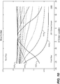
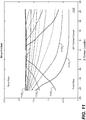
- Figures 9 , 10 and 11 illustrate a flattening of gain for several theater installations and corresponding performance improvements according to embodiments of the present invention.
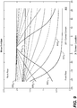
- Fig. 9 is a performance graph 900 of left and center isle seating positions in a theater using a dual projector and a 2.4 gain with the projectors located at opposite sides on the back wall (e.g., 25 feet from the center of the back wall in a 50 ft. wide auditorium).
- the projectors are 1 ⁇ 2 power projectors, so the gain figures can be more easily compared to single projector installations.
- FIG. 9 shows gain curves for increasing distance from a front row to a back row for the left isle (curves 910 1 to 910 n ) and a center isle (curves 920 1 to 920 n ).
- the measured gain is generally lower than in the single projector installation of Fig. 8 , but the gain across all seat locations is substantially flatter.
- Fig. 9 also illustrate higher gain and flatter gain curve than the single projector 2.2 gain screen example in Fig. 7 .
- Fig. 10 is a performance graph 1000 of left and center isle seating positions in a theater using a dual projector and a 2.4 gain with the projectors located on the side walls and 1/10 th a distance to the screen forward of the back wall (e.g., 7 feet forward of the back wall in a 70 ft. length auditorium).
- the projectors modeled are 1 ⁇ 2 power.
- Fig. 10 shows gain curves for increasing distance from a front row to a back row for the left isle (curves 1010 1 to 1010 n ) and a center isle (curves 1020 1 to 1020 n ). As can be seen in Fig. 10 , the curves are substantially flatter (especially in the center). Although the gain goes down (roughly equivalent to the 1.8 gain screen example of Fig. 6 ) it is much flatter.
- Fig. 11 is a performance graph 1100 of left and center isle seating positions in a theater using a triple projector and a 2.4 gain with two projectors located on the side walls and approximately 1/5 th a distance to the screen from the back wall (e.g., 15 feet forward of the back wall in a 70ft. length auditorium), and a third projector located at the center of the back wall.
- the projectors modeled are 1/3 power.
- Fig. 11 shows gain curves for increasing distance from a front row to a back row for the left isle (curves 1110 1 to 1110 n ) and a center isle (curves 1120 1 to 1120 n ).
- the triple projector implementation produces an exceedingly flat gain curve.
- the present invention includes a computer program product which is a storage medium (media) having instructions stored thereon/in which can be used to control, or cause, a computer to perform any of the processes of the present invention.
- the storage medium can include, but is not limited to, any type of disk including floppy disks, mini disks (MD's), optical discs, DVD, HD-DVD, Blue-ray, CD-ROMS, CD or DVD RW+/-, micro-drive, and magneto-optical disks, ROMs, RAMs, EPROMs, EEPROMs, DRAMs, VRAMs, flash memory devices (including flash cards, memory sticks), magnetic or optical cards, SIM cards, MEMS, nanosystems (including molecular memory ICs), RAID devices, remote data storage/archive/warehousing, or any type of media or device suitable for storing instructions and/or data.
- the present invention includes software for controlling both the hardware of the general purpose/specialized computer or microprocessor, and for enabling the computer or microprocessor to interact with a human user or other mechanism utilizing the results of the present invention.
- software may include, but is not limited to, device drivers, operating systems, and user applications.
- computer readable media further includes software for performing the present invention, as described above.
- ⁇ Included in the programming (software) of the general/specialized computer or microprocessor are software modules for implementing the teachings of the present invention, including, but not limited to, calculating and/or correcting for trapezoidal effects, including trapezoidal effects occurring because of spacing between projectors, color correction, energizing modulating devices according to image data and any applied corrections, registration of images, and the display, storage, or communication of results according to the processes of the present invention.
- the present invention may suitably comprise, consist of, or consist essentially of, any of element (the various parts or features of the invention) and their equivalents as described herein. Further, the present invention illustratively disclosed herein may be practiced in the absence of any element, whether or not specifically disclosed herein. Obviously, numerous modifications and variations of the present invention are possible in light of the above teachings. It is therefore to be understood that within the scope of the appended claims, the invention may be practiced otherwise than as specifically described herein.
Landscapes
- Engineering & Computer Science (AREA)
- Multimedia (AREA)
- Signal Processing (AREA)
- Physics & Mathematics (AREA)
- General Physics & Mathematics (AREA)
- Geometry (AREA)
- Projection Apparatus (AREA)
- Transforming Electric Information Into Light Information (AREA)
- Testing, Inspecting, Measuring Of Stereoscopic Televisions And Televisions (AREA)
- Overhead Projectors And Projection Screens (AREA)
Applications Claiming Priority (2)
| Application Number | Priority Date | Filing Date | Title |
|---|---|---|---|
| US201161496497P | 2011-06-13 | 2011-06-13 | |
| PCT/US2012/041230 WO2012173851A2 (en) | 2011-06-13 | 2012-06-07 | High directivity screens |
Publications (2)
| Publication Number | Publication Date |
|---|---|
| EP2719185A2 EP2719185A2 (en) | 2014-04-16 |
| EP2719185B1 true EP2719185B1 (en) | 2020-12-23 |
Family
ID=46582053
Family Applications (1)
| Application Number | Title | Priority Date | Filing Date |
|---|---|---|---|
| EP12740240.2A Active EP2719185B1 (en) | 2011-06-13 | 2012-06-07 | Projection system |
Country Status (6)
| Country | Link |
|---|---|
| US (1) | US9335614B2 (enExample) |
| EP (1) | EP2719185B1 (enExample) |
| JP (2) | JP6388830B2 (enExample) |
| CN (1) | CN103621071B (enExample) |
| ES (1) | ES2844325T3 (enExample) |
| WO (1) | WO2012173851A2 (enExample) |
Families Citing this family (5)
| Publication number | Priority date | Publication date | Assignee | Title |
|---|---|---|---|---|
| KR101598057B1 (ko) * | 2013-11-29 | 2016-02-26 | 씨제이씨지브이 주식회사 | 다면 상영관의 컨텐츠 사이즈 노멀라이징 방법, 장치 및 컴퓨터로 판독 가능한 기록 매체 |
| CN105391995A (zh) * | 2015-12-17 | 2016-03-09 | 广州玖的数码科技有限公司 | 一种双通道融合投影校准方法和系统 |
| US10809543B2 (en) | 2017-01-23 | 2020-10-20 | Dolby Laboratories Licensing Corporation | Glasses for spectral and 3D imaging |
| JP6872178B2 (ja) * | 2017-12-28 | 2021-05-19 | ウシオ電機株式会社 | 投影システム |
| CN115776557A (zh) | 2018-05-16 | 2023-03-10 | 杜比实验室特许公司 | 投影仪控制器及投影控制方法 |
Citations (2)
| Publication number | Priority date | Publication date | Assignee | Title |
|---|---|---|---|---|
| US20070091118A1 (en) * | 2005-10-26 | 2007-04-26 | Allen William J | Image display system and method |
| US20090231551A1 (en) * | 2008-03-11 | 2009-09-17 | Robe Show Lighting S.R.O. | Digital imaging system |
Family Cites Families (29)
| Publication number | Priority date | Publication date | Assignee | Title |
|---|---|---|---|---|
| US4025160A (en) | 1973-09-19 | 1977-05-24 | Robert H. Reibel | Dual purpose projection screen |
| US6392689B1 (en) | 1991-02-21 | 2002-05-21 | Eugene Dolgoff | System for displaying moving images pseudostereoscopically |
| US5189452A (en) | 1991-12-09 | 1993-02-23 | General Electric Company | Real image projection system |
| US5175575A (en) | 1992-01-28 | 1992-12-29 | Contraves Usa-Ssi | Segmented ellipsoidal projection system |
| US5376980A (en) | 1992-01-28 | 1994-12-27 | Contraves Usa-Ssi | Segmented torus screen |
| JP2740994B2 (ja) * | 1992-07-24 | 1998-04-15 | 株式会社有沢製作所 | 再帰反射スクリーン |
| JPH06276465A (ja) * | 1993-03-19 | 1994-09-30 | Matsushita Electric Ind Co Ltd | 投写型画像表示装置 |
| US5541769A (en) | 1994-11-18 | 1996-07-30 | Hughes Training, Inc. | Uniform-brightness, high-gain display structures and methods |
| EP0778483A4 (en) | 1995-06-26 | 1998-09-30 | Nissho Giken Kk | PROJECTION APPARATUS |
| US6381068B1 (en) | 1999-03-19 | 2002-04-30 | 3M Innovative Properties Company | Reflective projection screen and projection system |
| US6483643B1 (en) | 1999-04-08 | 2002-11-19 | Larry Zuchowski | Controlled gain projection screen |
| US6771272B2 (en) | 2000-03-17 | 2004-08-03 | Sun Microsystems, Inc. | Graphics system having a super-sampled sample buffer with hot spot correction |
| JP2001339742A (ja) | 2000-03-21 | 2001-12-07 | Olympus Optical Co Ltd | 立体映像プロジェクション装置、及びその補正量演算装置 |
| MXPA05003106A (es) | 2002-09-20 | 2005-06-22 | Honeywell Int Inc | Pantalla de visualizacion de alta eficiencia. |
| JP4050672B2 (ja) | 2003-08-08 | 2008-02-20 | オリンパス株式会社 | 再帰性光学スクリーン及びそれを用いた観察装置 |
| JP2005080261A (ja) | 2003-09-04 | 2005-03-24 | Nec Viewtechnology Ltd | 映像投射方法、及び、この方法に適用されるプロジェクタ |
| JP2005107011A (ja) * | 2003-09-29 | 2005-04-21 | Daicel Chem Ind Ltd | 反射スクリーン、それを用いた表示方法および表示装置 |
| EP1692566A4 (en) | 2003-10-09 | 2009-02-25 | Merlin Technology Ltd Liabilit | PROJECTION RECEPTION SURFACE, WHICH WORKS IN AMBIENT LIGHT |
| JP3960325B2 (ja) * | 2004-08-11 | 2007-08-15 | セイコーエプソン株式会社 | ディスプレイ装置およびディスプレイ装置における画像情報生成方法 |
| JP2006337639A (ja) * | 2005-06-01 | 2006-12-14 | Tadashi Yamauchi | 指向性スクリーン及び画像投影システム |
| JP2008102193A (ja) * | 2006-10-17 | 2008-05-01 | Seiko Epson Corp | 偏光変換素子、照明装置及び画像表示装置 |
| US7670004B2 (en) * | 2006-10-18 | 2010-03-02 | Real D | Dual ZScreen® projection |
| US7784938B2 (en) | 2007-05-09 | 2010-08-31 | Dolby Laboratories Licensing Corporation | Method and system for shaped glasses and viewing 3D images |
| GB2452347A (en) | 2007-08-27 | 2009-03-04 | Hae-Yong Choi | Portable data projector and curved reflective screen combination in case. |
| TW200921254A (en) * | 2007-11-06 | 2009-05-16 | Bright View Technologies Inc | Portable front projection screens |
| US8267524B2 (en) * | 2008-01-18 | 2012-09-18 | Seiko Epson Corporation | Projection system and projector with widened projection of light for projection onto a close object |
| EP2240825B1 (en) | 2008-01-28 | 2017-07-19 | RealD Inc. | Polarization preserving front projection screen |
| US20090219381A1 (en) * | 2008-03-03 | 2009-09-03 | Disney Enterprises, Inc., A Delaware Corporation | System and/or method for processing three dimensional images |
| HU0900478D0 (en) * | 2009-07-31 | 2009-09-28 | Holografika Hologrameloeallito | Method and apparatus for displaying 3d images |
-
2012
- 2012-06-07 JP JP2014515879A patent/JP6388830B2/ja active Active
- 2012-06-07 ES ES12740240T patent/ES2844325T3/es active Active
- 2012-06-07 CN CN201280029063.9A patent/CN103621071B/zh active Active
- 2012-06-07 WO PCT/US2012/041230 patent/WO2012173851A2/en not_active Ceased
- 2012-06-07 US US14/123,951 patent/US9335614B2/en active Active
- 2012-06-07 EP EP12740240.2A patent/EP2719185B1/en active Active
-
2016
- 2016-11-04 JP JP2016215757A patent/JP6546142B2/ja active Active
Patent Citations (2)
| Publication number | Priority date | Publication date | Assignee | Title |
|---|---|---|---|---|
| US20070091118A1 (en) * | 2005-10-26 | 2007-04-26 | Allen William J | Image display system and method |
| US20090231551A1 (en) * | 2008-03-11 | 2009-09-17 | Robe Show Lighting S.R.O. | Digital imaging system |
Also Published As
| Publication number | Publication date |
|---|---|
| ES2844325T3 (es) | 2021-07-21 |
| WO2012173851A3 (en) | 2013-05-10 |
| JP2014525160A (ja) | 2014-09-25 |
| CN103621071B (zh) | 2017-05-31 |
| JP6388830B2 (ja) | 2018-09-12 |
| JP6546142B2 (ja) | 2019-07-17 |
| CN103621071A (zh) | 2014-03-05 |
| US9335614B2 (en) | 2016-05-10 |
| US20140204186A1 (en) | 2014-07-24 |
| WO2012173851A2 (en) | 2012-12-20 |
| JP2017063457A (ja) | 2017-03-30 |
| EP2719185A2 (en) | 2014-04-16 |
Similar Documents
| Publication | Publication Date | Title |
|---|---|---|
| US11668951B2 (en) | 3D projection system using laser light sources | |
| US11585971B2 (en) | System for 3D image projections and viewing | |
| US8403489B2 (en) | Spectral separation filters for 3D stereoscopic D-cinema presentation | |
| JP6546142B2 (ja) | 高指向性のスクリーン | |
| US20080043209A1 (en) | Image display system with channel selection device | |
| US10073328B2 (en) | Reducing angular spread in digital image projection | |
| US20130342814A1 (en) | Multiview projector system | |
| EP2987027B1 (en) | Dual projection in short screen distance | |
| US7995092B2 (en) | Two-dimensional and three-dimensional projecting | |
| HK40028062A (en) | 3d projection system using laser light sources | |
| HK1241615A1 (en) | Laser display system, 3d viewing glasses and method for preparing 3d image | |
| HK1241615B (zh) | 激光显示系统、3d 观看眼镜及3d 图像制备方法 |
Legal Events
| Date | Code | Title | Description |
|---|---|---|---|
| PUAI | Public reference made under article 153(3) epc to a published international application that has entered the european phase |
Free format text: ORIGINAL CODE: 0009012 |
|
| 17P | Request for examination filed |
Effective date: 20140113 |
|
| AK | Designated contracting states |
Kind code of ref document: A2 Designated state(s): AL AT BE BG CH CY CZ DE DK EE ES FI FR GB GR HR HU IE IS IT LI LT LU LV MC MK MT NL NO PL PT RO RS SE SI SK SM TR |
|
| DAX | Request for extension of the european patent (deleted) | ||
| RAP1 | Party data changed (applicant data changed or rights of an application transferred) |
Owner name: DOLBY LABORATORIES LICENSING CORPORATION |
|
| STAA | Information on the status of an ep patent application or granted ep patent |
Free format text: STATUS: EXAMINATION IS IN PROGRESS |
|
| 17Q | First examination report despatched |
Effective date: 20171109 |
|
| GRAP | Despatch of communication of intention to grant a patent |
Free format text: ORIGINAL CODE: EPIDOSNIGR1 |
|
| STAA | Information on the status of an ep patent application or granted ep patent |
Free format text: STATUS: GRANT OF PATENT IS INTENDED |
|
| RIC1 | Information provided on ipc code assigned before grant |
Ipc: H04N 13/337 20180101ALI20200623BHEP Ipc: H04N 13/363 20180101ALI20200623BHEP Ipc: H04N 9/31 20060101AFI20200623BHEP |
|
| INTG | Intention to grant announced |
Effective date: 20200709 |
|
| GRAS | Grant fee paid |
Free format text: ORIGINAL CODE: EPIDOSNIGR3 |
|
| GRAA | (expected) grant |
Free format text: ORIGINAL CODE: 0009210 |
|
| STAA | Information on the status of an ep patent application or granted ep patent |
Free format text: STATUS: THE PATENT HAS BEEN GRANTED |
|
| AK | Designated contracting states |
Kind code of ref document: B1 Designated state(s): AL AT BE BG CH CY CZ DE DK EE ES FI FR GB GR HR HU IE IS IT LI LT LU LV MC MK MT NL NO PL PT RO RS SE SI SK SM TR |
|
| REG | Reference to a national code |
Ref country code: GB Ref legal event code: FG4D |
|
| REG | Reference to a national code |
Ref country code: DE Ref legal event code: R096 Ref document number: 602012073839 Country of ref document: DE |
|
| REG | Reference to a national code |
Ref country code: AT Ref legal event code: REF Ref document number: 1348836 Country of ref document: AT Kind code of ref document: T Effective date: 20210115 |
|
| REG | Reference to a national code |
Ref country code: IE Ref legal event code: FG4D |
|
| PG25 | Lapsed in a contracting state [announced via postgrant information from national office to epo] |
Ref country code: GR Free format text: LAPSE BECAUSE OF FAILURE TO SUBMIT A TRANSLATION OF THE DESCRIPTION OR TO PAY THE FEE WITHIN THE PRESCRIBED TIME-LIMIT Effective date: 20210324 Ref country code: FI Free format text: LAPSE BECAUSE OF FAILURE TO SUBMIT A TRANSLATION OF THE DESCRIPTION OR TO PAY THE FEE WITHIN THE PRESCRIBED TIME-LIMIT Effective date: 20201223 Ref country code: RS Free format text: LAPSE BECAUSE OF FAILURE TO SUBMIT A TRANSLATION OF THE DESCRIPTION OR TO PAY THE FEE WITHIN THE PRESCRIBED TIME-LIMIT Effective date: 20201223 Ref country code: NO Free format text: LAPSE BECAUSE OF FAILURE TO SUBMIT A TRANSLATION OF THE DESCRIPTION OR TO PAY THE FEE WITHIN THE PRESCRIBED TIME-LIMIT Effective date: 20210323 |
|
| REG | Reference to a national code |
Ref country code: AT Ref legal event code: MK05 Ref document number: 1348836 Country of ref document: AT Kind code of ref document: T Effective date: 20201223 |
|
| REG | Reference to a national code |
Ref country code: NL Ref legal event code: MP Effective date: 20201223 |
|
| PG25 | Lapsed in a contracting state [announced via postgrant information from national office to epo] |
Ref country code: BG Free format text: LAPSE BECAUSE OF FAILURE TO SUBMIT A TRANSLATION OF THE DESCRIPTION OR TO PAY THE FEE WITHIN THE PRESCRIBED TIME-LIMIT Effective date: 20210323 Ref country code: LV Free format text: LAPSE BECAUSE OF FAILURE TO SUBMIT A TRANSLATION OF THE DESCRIPTION OR TO PAY THE FEE WITHIN THE PRESCRIBED TIME-LIMIT Effective date: 20201223 Ref country code: SE Free format text: LAPSE BECAUSE OF FAILURE TO SUBMIT A TRANSLATION OF THE DESCRIPTION OR TO PAY THE FEE WITHIN THE PRESCRIBED TIME-LIMIT Effective date: 20201223 |
|
| PG25 | Lapsed in a contracting state [announced via postgrant information from national office to epo] |
Ref country code: NL Free format text: LAPSE BECAUSE OF FAILURE TO SUBMIT A TRANSLATION OF THE DESCRIPTION OR TO PAY THE FEE WITHIN THE PRESCRIBED TIME-LIMIT Effective date: 20201223 Ref country code: HR Free format text: LAPSE BECAUSE OF FAILURE TO SUBMIT A TRANSLATION OF THE DESCRIPTION OR TO PAY THE FEE WITHIN THE PRESCRIBED TIME-LIMIT Effective date: 20201223 |
|
| REG | Reference to a national code |
Ref country code: LT Ref legal event code: MG9D |
|
| REG | Reference to a national code |
Ref country code: ES Ref legal event code: FG2A Ref document number: 2844325 Country of ref document: ES Kind code of ref document: T3 Effective date: 20210721 |
|
| PG25 | Lapsed in a contracting state [announced via postgrant information from national office to epo] |
Ref country code: PT Free format text: LAPSE BECAUSE OF FAILURE TO SUBMIT A TRANSLATION OF THE DESCRIPTION OR TO PAY THE FEE WITHIN THE PRESCRIBED TIME-LIMIT Effective date: 20210423 Ref country code: SK Free format text: LAPSE BECAUSE OF FAILURE TO SUBMIT A TRANSLATION OF THE DESCRIPTION OR TO PAY THE FEE WITHIN THE PRESCRIBED TIME-LIMIT Effective date: 20201223 Ref country code: RO Free format text: LAPSE BECAUSE OF FAILURE TO SUBMIT A TRANSLATION OF THE DESCRIPTION OR TO PAY THE FEE WITHIN THE PRESCRIBED TIME-LIMIT Effective date: 20201223 Ref country code: LT Free format text: LAPSE BECAUSE OF FAILURE TO SUBMIT A TRANSLATION OF THE DESCRIPTION OR TO PAY THE FEE WITHIN THE PRESCRIBED TIME-LIMIT Effective date: 20201223 Ref country code: EE Free format text: LAPSE BECAUSE OF FAILURE TO SUBMIT A TRANSLATION OF THE DESCRIPTION OR TO PAY THE FEE WITHIN THE PRESCRIBED TIME-LIMIT Effective date: 20201223 Ref country code: CZ Free format text: LAPSE BECAUSE OF FAILURE TO SUBMIT A TRANSLATION OF THE DESCRIPTION OR TO PAY THE FEE WITHIN THE PRESCRIBED TIME-LIMIT Effective date: 20201223 Ref country code: SM Free format text: LAPSE BECAUSE OF FAILURE TO SUBMIT A TRANSLATION OF THE DESCRIPTION OR TO PAY THE FEE WITHIN THE PRESCRIBED TIME-LIMIT Effective date: 20201223 |
|
| PG25 | Lapsed in a contracting state [announced via postgrant information from national office to epo] |
Ref country code: AT Free format text: LAPSE BECAUSE OF FAILURE TO SUBMIT A TRANSLATION OF THE DESCRIPTION OR TO PAY THE FEE WITHIN THE PRESCRIBED TIME-LIMIT Effective date: 20201223 Ref country code: PL Free format text: LAPSE BECAUSE OF FAILURE TO SUBMIT A TRANSLATION OF THE DESCRIPTION OR TO PAY THE FEE WITHIN THE PRESCRIBED TIME-LIMIT Effective date: 20201223 |
|
| REG | Reference to a national code |
Ref country code: DE Ref legal event code: R097 Ref document number: 602012073839 Country of ref document: DE |
|
| PG25 | Lapsed in a contracting state [announced via postgrant information from national office to epo] |
Ref country code: IS Free format text: LAPSE BECAUSE OF FAILURE TO SUBMIT A TRANSLATION OF THE DESCRIPTION OR TO PAY THE FEE WITHIN THE PRESCRIBED TIME-LIMIT Effective date: 20210423 |
|
| PG25 | Lapsed in a contracting state [announced via postgrant information from national office to epo] |
Ref country code: AL Free format text: LAPSE BECAUSE OF FAILURE TO SUBMIT A TRANSLATION OF THE DESCRIPTION OR TO PAY THE FEE WITHIN THE PRESCRIBED TIME-LIMIT Effective date: 20201223 |
|
| PLBE | No opposition filed within time limit |
Free format text: ORIGINAL CODE: 0009261 |
|
| STAA | Information on the status of an ep patent application or granted ep patent |
Free format text: STATUS: NO OPPOSITION FILED WITHIN TIME LIMIT |
|
| PG25 | Lapsed in a contracting state [announced via postgrant information from national office to epo] |
Ref country code: DK Free format text: LAPSE BECAUSE OF FAILURE TO SUBMIT A TRANSLATION OF THE DESCRIPTION OR TO PAY THE FEE WITHIN THE PRESCRIBED TIME-LIMIT Effective date: 20201223 |
|
| 26N | No opposition filed |
Effective date: 20210924 |
|
| PG25 | Lapsed in a contracting state [announced via postgrant information from national office to epo] |
Ref country code: MC Free format text: LAPSE BECAUSE OF FAILURE TO SUBMIT A TRANSLATION OF THE DESCRIPTION OR TO PAY THE FEE WITHIN THE PRESCRIBED TIME-LIMIT Effective date: 20201223 |
|
| REG | Reference to a national code |
Ref country code: CH Ref legal event code: PL |
|
| PG25 | Lapsed in a contracting state [announced via postgrant information from national office to epo] |
Ref country code: SI Free format text: LAPSE BECAUSE OF FAILURE TO SUBMIT A TRANSLATION OF THE DESCRIPTION OR TO PAY THE FEE WITHIN THE PRESCRIBED TIME-LIMIT Effective date: 20201223 |
|
| REG | Reference to a national code |
Ref country code: BE Ref legal event code: MM Effective date: 20210630 |
|
| PG25 | Lapsed in a contracting state [announced via postgrant information from national office to epo] |
Ref country code: LU Free format text: LAPSE BECAUSE OF NON-PAYMENT OF DUE FEES Effective date: 20210607 |
|
| PG25 | Lapsed in a contracting state [announced via postgrant information from national office to epo] |
Ref country code: LI Free format text: LAPSE BECAUSE OF NON-PAYMENT OF DUE FEES Effective date: 20210630 Ref country code: IE Free format text: LAPSE BECAUSE OF NON-PAYMENT OF DUE FEES Effective date: 20210607 Ref country code: CH Free format text: LAPSE BECAUSE OF NON-PAYMENT OF DUE FEES Effective date: 20210630 |
|
| PG25 | Lapsed in a contracting state [announced via postgrant information from national office to epo] |
Ref country code: IS Free format text: LAPSE BECAUSE OF FAILURE TO SUBMIT A TRANSLATION OF THE DESCRIPTION OR TO PAY THE FEE WITHIN THE PRESCRIBED TIME-LIMIT Effective date: 20210423 |
|
| PG25 | Lapsed in a contracting state [announced via postgrant information from national office to epo] |
Ref country code: BE Free format text: LAPSE BECAUSE OF NON-PAYMENT OF DUE FEES Effective date: 20210630 |
|
| PG25 | Lapsed in a contracting state [announced via postgrant information from national office to epo] |
Ref country code: HU Free format text: LAPSE BECAUSE OF FAILURE TO SUBMIT A TRANSLATION OF THE DESCRIPTION OR TO PAY THE FEE WITHIN THE PRESCRIBED TIME-LIMIT; INVALID AB INITIO Effective date: 20120607 Ref country code: CY Free format text: LAPSE BECAUSE OF FAILURE TO SUBMIT A TRANSLATION OF THE DESCRIPTION OR TO PAY THE FEE WITHIN THE PRESCRIBED TIME-LIMIT Effective date: 20201223 |
|
| P01 | Opt-out of the competence of the unified patent court (upc) registered |
Effective date: 20230512 |
|
| PG25 | Lapsed in a contracting state [announced via postgrant information from national office to epo] |
Ref country code: MK Free format text: LAPSE BECAUSE OF FAILURE TO SUBMIT A TRANSLATION OF THE DESCRIPTION OR TO PAY THE FEE WITHIN THE PRESCRIBED TIME-LIMIT Effective date: 20201223 |
|
| PG25 | Lapsed in a contracting state [announced via postgrant information from national office to epo] |
Ref country code: MT Free format text: LAPSE BECAUSE OF FAILURE TO SUBMIT A TRANSLATION OF THE DESCRIPTION OR TO PAY THE FEE WITHIN THE PRESCRIBED TIME-LIMIT Effective date: 20201223 |
|
| PGFP | Annual fee paid to national office [announced via postgrant information from national office to epo] |
Ref country code: DE Payment date: 20250520 Year of fee payment: 14 |
|
| PGFP | Annual fee paid to national office [announced via postgrant information from national office to epo] |
Ref country code: GB Payment date: 20250520 Year of fee payment: 14 |
|
| PGFP | Annual fee paid to national office [announced via postgrant information from national office to epo] |
Ref country code: IT Payment date: 20250520 Year of fee payment: 14 |
|
| PGFP | Annual fee paid to national office [announced via postgrant information from national office to epo] |
Ref country code: FR Payment date: 20250520 Year of fee payment: 14 |
|
| PGFP | Annual fee paid to national office [announced via postgrant information from national office to epo] |
Ref country code: ES Payment date: 20250701 Year of fee payment: 14 |
|
| PG25 | Lapsed in a contracting state [announced via postgrant information from national office to epo] |
Ref country code: TR Free format text: LAPSE BECAUSE OF FAILURE TO SUBMIT A TRANSLATION OF THE DESCRIPTION OR TO PAY THE FEE WITHIN THE PRESCRIBED TIME-LIMIT Effective date: 20201223 |