EP2716620A2 - Verfahren und Vorrichtung zur Herstellung von pelletformigem Düngemittel - Google Patents
Verfahren und Vorrichtung zur Herstellung von pelletformigem Düngemittel Download PDFInfo
- Publication number
- EP2716620A2 EP2716620A2 EP13184892.1A EP13184892A EP2716620A2 EP 2716620 A2 EP2716620 A2 EP 2716620A2 EP 13184892 A EP13184892 A EP 13184892A EP 2716620 A2 EP2716620 A2 EP 2716620A2
- Authority
- EP
- European Patent Office
- Prior art keywords
- carrier
- additive
- dispenser
- fertilizing
- dispersion
- Prior art date
- Legal status (The legal status is an assumption and is not a legal conclusion. Google has not performed a legal analysis and makes no representation as to the accuracy of the status listed.)
- Granted
Links
Images
Classifications
-
- B—PERFORMING OPERATIONS; TRANSPORTING
- B01—PHYSICAL OR CHEMICAL PROCESSES OR APPARATUS IN GENERAL
- B01J—CHEMICAL OR PHYSICAL PROCESSES, e.g. CATALYSIS OR COLLOID CHEMISTRY; THEIR RELEVANT APPARATUS
- B01J2/00—Processes or devices for granulating materials, e.g. fertilisers in general; Rendering particulate materials free flowing in general, e.g. making them hydrophobic
- B01J2/20—Processes or devices for granulating materials, e.g. fertilisers in general; Rendering particulate materials free flowing in general, e.g. making them hydrophobic by expressing the material, e.g. through sieves and fragmenting the extruded length
-
- B—PERFORMING OPERATIONS; TRANSPORTING
- B01—PHYSICAL OR CHEMICAL PROCESSES OR APPARATUS IN GENERAL
- B01J—CHEMICAL OR PHYSICAL PROCESSES, e.g. CATALYSIS OR COLLOID CHEMISTRY; THEIR RELEVANT APPARATUS
- B01J2/00—Processes or devices for granulating materials, e.g. fertilisers in general; Rendering particulate materials free flowing in general, e.g. making them hydrophobic
- B01J2/28—Processes or devices for granulating materials, e.g. fertilisers in general; Rendering particulate materials free flowing in general, e.g. making them hydrophobic using special binding agents
-
- C—CHEMISTRY; METALLURGY
- C05—FERTILISERS; MANUFACTURE THEREOF
- C05D—INORGANIC FERTILISERS NOT COVERED BY SUBCLASSES C05B, C05C; FERTILISERS PRODUCING CARBON DIOXIDE
- C05D9/00—Other inorganic fertilisers
- C05D9/02—Other inorganic fertilisers containing trace elements
-
- C—CHEMISTRY; METALLURGY
- C05—FERTILISERS; MANUFACTURE THEREOF
- C05G—MIXTURES OF FERTILISERS COVERED INDIVIDUALLY BY DIFFERENT SUBCLASSES OF CLASS C05; MIXTURES OF ONE OR MORE FERTILISERS WITH MATERIALS NOT HAVING A SPECIFIC FERTILISING ACTIVITY, e.g. PESTICIDES, SOIL-CONDITIONERS, WETTING AGENTS; FERTILISERS CHARACTERISED BY THEIR FORM
- C05G5/00—Fertilisers characterised by their form
- C05G5/10—Solid or semi-solid fertilisers, e.g. powders
- C05G5/12—Granules or flakes
Definitions
- the present invention refers to a process and apparatus for producing a fertilizer in pellet form to be typically used in the agricultural field for recovering untilled or abandoned farmlands or for fertilizing farmlands, and to the fertilizer in pellet form produced in this way.
- fertilizers adapted to create, reform, conserve and/or increase the fertility of farmlands, in other words adapted to correct the nutritional properties of farmlands to cultivate them with excellent or anyway very good crop yields.
- the farmland is enriched with nutritional elements by fertilizers, the physical properties of the farmland are improved by amendments, while the farmland reactions are corrected by corrective fertilizers.
- the fertilizers in pellet form which comprise suitable batched quantities (by weight and percentage) of fertilizing substances are of particular interest.
- fertilizers in pellet form enables a simple deposition and also a correct batching of the fertilizer to be distributed on the farmland so that an operator can, in dependence of the type of treatment, set the most suitable composition and deposit the fertilizer where it is required and with the suitable quantities.
- fertilizing pellets further enables to apply with high accuracy the fertilizer in the desired area: so that it is possible to markedly reduce the quantity of fertilizer used in comparison, for example, with a fertilization performed by liquid solutions applied by means or sprinklers.
- the pellet production is done by supplying a liquid fertilizing dispersion to a pelletizer adapted to form said pellets on a conveyor belt. Then, the liquid (or semi-liquid) pellets are cooled down so that they can be supplied in a solid state ready for their use.
- the above mentioned process makes use of an apparatus having a batch device dedicated to mix the carrier with various additives, and a device separate from the latter for supplying the substance once the dispersion is ready.
- the fertilizer components are introduced in a mixer and then are subjected to a mild intimate mixing process for homogenizing the components; this batch process takes a few tenths of minutes based on the volumes to be prepared. During this step, the pelletizer is inoperative. Once the dispersion is ready, the same is supplied to the pelletizer for its production.
- composition entails to modify the plant (type of mill, distance between the milling surfaces, milling speed, etcetera), and to modify all the process parameters requiring downtime and a new setting.
- a first object of the invention is to provide a process for producing a fertilizer in pellet form, which is extremely flexible and easily enables to modify the quantities of the product and/or the composition of the pellets without requiring deep changes and/or long plant downtimes.
- a further object is to provide an efficient process enabling a fast pellet production in order to enable a reduction of the product costs.
- a further object of the invention is to provide a process for producing a fertilizer in pellet form enabling to correctly mix and supply the fertilizer so that each pellet substantially contains the same quantity of the fertilizing substance and has the same composition.
- An object is also to provide a fertilizer in pellet form which is at the same time economical and practical, by reducing the cost of some components and eventually improving the capabilities of homogenizing the dispersion.
- a further subordinate object is to provide a fertilizing composition wherein the percentage by weight of micronutrients can be increased by reducing the number of other components without compromising the synergy among the substances forming a pellet.
- a further object of the invention is to provide an apparatus for producing a fertilizer in pellet form having the lowest number of components in order to make highly reliable and economical the overall productive system.
- carrier (F) is supplied to dispenser (6) in a liquid or solid form, particularly in a powdery, granular or pellet form.
- carrier (F) when is in a solid form, is liquefied when is mixed in dispenser (6).
- the step of mixing the carrier (F) and additive (A) inside dispenser (6) for obtaining a fertilizing dispersion (C) comprises a sub-step of putting in rotation the mixing element (30) for advancing and mixing together the carrier and additive.
- a rotation axis of the mixing element (30) being substantially parallel to, and particularly substantially coinciding with the advancing direction.
- the mixing element (30) comprises an advancing screw or helix and is movable inside a containment jacket.
- the step of mixing the carrier (F) and additive (A) inside the dispenser (6) for obtaining a fertilizing dispersion (C) comprises a sub-step of mixing by at least one extruder.
- the extruder comprises a single-screw or twin-screw extruder.
- the step of mixing the carrier (F) and additive (A) inside the dispenser (6) for obtaining a fertilizing dispersion (C) comprises a sub-step of pushing the carrier (F) and additive (A) by a mixing element (30).
- the step of pushing the carrier (F) and additive (A), by the mixing element (30), comprises the step of pushing the carrier and additive along and about the advancement direction (10) by following a substantially helical path.
- an inlet (6b) of additive dispenser (6) is upstream, along the advancement direction (10), with respect to a carrier inlet (6a).
- the additive contacts the carrier following its movement along the advancement direction (10) and mixes with the latter inside the extruder (6).
- an inlet (6b) to the additive extruder being upstream, along the advancement direction (10), with respect to a carrier inlet (6a), the additive contacting the carrier following its movement along the advancement direction (10) and mixing with the latter inside the extruder (6).
- the step of continuously supplying the fertilizing dispersion (C) enables to supply a fertilizing dispersion (C) flow rate greater than 8,000 kg/hr.
- the step of continuously supplying the fertilizing dispersion (C) enables to supply a fertilizing dispersion (C) flow rate comprised between 11,000 kg/hr and 15,000 kg/hr.
- the step of continuously sending the carrier (F) to the dispenser (6) comprises a sub-step of batching the flow rate of the latter arriving from the source (4) and entering the dispenser (6), adapted to meter the carrier (F) quantity present in the fertilizing dispersion (C).
- the batching is obtained by controlling an advancement pump (13) by a control unit (9).
- pump (13) is a geared pump.
- the carrier (F) flow rate entering the dispenser (6) is greater than 7,000 kg/hr.
- carrier (F) flow rate entering the dispenser (6) is comprised between 9,000 kg/hr and 10,000 kg/hr.
- the step of continuously sending the additive (A) to the dispenser (6) comprises a sub-step of batching the quantity of the latter arriving from the additive (5) source and entering the dispenser (6), adapted to meter the quantity of additive of the fertilizing dispersion (C).
- the batching is particularly obtained by controlling an additive amount supplied by a gravimetric batcher (25).
- the additive (A) flow rate entering the dispenser (6) is greater than 1,800 kg/hr.
- the additive (A) flow rate entering the dispenser (6) is comprised between 2,000 kg/hr and 2,400 kg/hr.
- the fertilizing dispersion (C) exiting the dispenser (6) has a percentage by weight of carrier (F) greater than 70%.
- the fertilizing dispersion (C), exiting the dispenser (6) has a percentage by weight of carrier (F) greater than 80%.
- the fertilizing dispersion (C), exiting the dispenser (6) has a percentage by weight of carrier (F) greater than 85%.
- the fertilizing dispersion (C), exiting the dispenser (6) has a percentage by weight of additive (A) greater than 2%.
- the fertilizing dispersion (C), exiting the dispenser (6) has a percentage by weight of additive (A) greater than 10%.
- the fertilizing dispersion (C), exiting the dispenser (6) has a percentage by weight of additive (A) greater than 15%.
- the carrier (F) comprises at least one substance comprised in the group of the following components: sulphur, urea, ammonium nitrate, paraffin, natural resin, synthetic resin.
- the additive (A) comprises at least one substance selected from the group of the following substances: clay, urea, sodium sulphates, potassium, calcium, ammonium, sodium phosphates, sodium carbonates, wood ashes, coal, wood shavings, vegetal masses, starches.
- the additive (A) comprises at least one substance adapted to perform a disgregating mechanical function of the pellet, for example in the presence of water or moisture.
- the substance of additive (A), adapted to perform a disgregating mechanical function of the pellet is at least selected from a group comprising bentonite, clay, wood or derivatives thereof, vegetal masses, starch, stubbles or combinations thereof.
- the additive (A) comprises at least one micronutrient substance.
- the micronutrient substance is selected from a group comprising urea, sodium sulphate, potassium, calcium, ammonium, sodium phosphates, sodium carbonates, wood ash or combinations thereof.
- the additive (A) comprises at least one sanitizing substance.
- the sanitizing substance is particularly coal.
- the fertilizing dispersion (C), exiting the dispenser (6) has a percentage by weight of additive greater than 2%.
- the fertilizing dispersion (C), exiting the dispenser (6) has a percentage by weight of additive greater than 10%.
- the fertilizing dispersion (C), exiting the dispenser (6) has a percentage by weight of additive greater than 15%.
- the additive (A) comprises at least one percentage by weight of a substance adapted to perform a disgregating mechanical function of the pellet.
- the substance of additive (A) is adapted to perform a disgregating mechanical function of the pellet for example in the presence of water or moisture.
- the substance of additive (A), adapted to perform a disgregating mechanical function of the pellet is comprised between 2 and 15% wt.
- the substance of additive (A), adapted to perform a disgregating mechanical function of the pellet is equal to or greater than 5% wt.
- the additive (A) comprises at least one percentage by weight of a micronutrient substance.
- the micronutrient substance is comprised between 0 and 15% wt.
- the micronutrient substance is equal to or greater than 2% wt and less than 12% in wt.
- the process comprises a step of heating the carrier (F), particularly in a liquid form, at least before the step of inserting the same inside the dispenser (6).
- the heating step is configured to take the carrier (F) to a temperature comprised between 70°C and 200°C.
- the heating step is configured to take the carrier (F) to a temperature comprised between 80°C and 180°C.
- the heating step is configured to take the carrier (F) to a temperature comprised between 90°C and 150°C.
- the support element is configured to take away the pellets from the pelletizer (7).
- the support element is a conveyor belt (8).
- the pellets forming step comprises at least the sub-step of sending the fertilizing dispersion (C) inside the pelletizer in a liquid or semi-liquid state.
- the pellets forming step comprises at least the sub-step of putting in rotation the pelletizer (7).
- the pellets forming step comprises at least the sub-step of supplying a predetermined quantity of fertilizing dispersion (C) on the support element, particularly on the conveyor belt, by a plurality of depositing nozzles.
- the pellets cooling step enables to take the latter to a temperature less than 70°C.
- the pellets cooling step enables to take the latter to a temperature less than 50°C.
- the pellets cooling step enables to take the latter to a temperature comprised between 20°C and 70°C.
- the pellets cooling step enables to take the latter to a temperature comprised between 20°C and 50°C.
- the process is configured to enable the continuous production of a number of fertilizing pellets greater than 40,000,000 pellets/hr.
- the process is configured to enable the continuous production of a number of fertilizing pellets greater than 42,000,000 pellets/hr.
- the process is configured to enable the continuous production of a number of fertilizing pellets greater than 43,000,000 pellets/hr.
- an apparatus (1) for producing a fertilizer in pellet form comprising:
- the dispenser (6) comprises at least one screw extruder configured to move the carrier (F) and additive (A) along the advancement direction (10) and simultaneously enable their mixing.
- the first supply line (2) is alternatively configured to enable the passage of at least one carrier (F) in a liquid form or carrier (F) in a solid form, particularly in a granular or pellet form.
- the carrier (F) when is in a solid form is liquefied during the mixing in the dispenser (6).
- the apparatus (1) comprises:
- the apparatus (1) comprises at least one pump (13) arranged in the first supply line (2) and adapted to supply the liquid carrier (F) to the dispenser (6).
- the pump (13) is for example a geared pump.
- the pump (13) is adapted to continuously supply the liquid carrier (F) to the dispenser (6).
- the pump (13) is configured to enable to regulate the carrier flow rate entering the dispenser (6).
- the apparatus (1) comprises at least one gravimetric batcher (25) associated to the second reservoir (12) and configured to enable to regulate the quantity of additive (A) exiting said second reservoir (12).
- the gravimetric batcher (25) is configured to particularly enable to adjust the weight of additive (A) exiting said second reservoir (12).
- the fertilizing dispersion (C) has a percentage of carrier (F) greater than 70%.
- the fertilizing dispersion (C) has a percentage of carrier (F) greater than 80%.
- the fertilizing dispersion (C) has a percentage of carrier (F) greater than 85%.
- the fertilizing dispersion (C) has a percentage of additive (A) greater than 2%.
- the fertilizing dispersion (C) has a percentage of additive (A) greater than 10%.
- the fertilizing dispersion (C) has a percentage of additive (A) greater than 15%.
- the carrier (F) comprises at least one comprised in the group of the following components: sulphur, urea, ammonium nitrate, paraffin, natural resin, synthetic resin.
- the additive (A) comprises at least one selected in the group of the following substances: clay, urea, sodium sulphate, potassium, calcium, ammonium, sodium phosphates, sodium carbonates, wood ash, coal, wood shavings, vegetal masses, starches.
- the apparatus (1) comprises a heating device (15) associated to at least said first reservoir (11) and/or supply line (2) and/or dispenser (6), and is configured to heat the carrier (F) present inside the latter.
- the heating device (15) is adapted to take the temperature of carrier (F) to a temperature comprised between 70°C and 200°C.
- the heating device (15) is adapted to take the temperature of carrier (F) to a temperature comprised between 80°C and 180°C.
- the heating device (15) is adapted to take the temperature of carrier (F) to a temperature comprised between 90°C and 150°C.
- the apparatus (1) comprises at least one conveyor belt (8) adapted to receive the fertilizing dispersion (C) drops formed by the pelletizer (7) and move them along an exit line (16).
- the apparatus comprises at least one cooling device associated to the conveyor belt (8).
- the cooling device is configured to lower the temperature of the fertilizing dispersion (C) exiting the pelletizer (6).
- the cooling device is configured to take the pellets moving on the conveyor belt to a temperature less than 70°C.
- the cooling device is configured to take the pellets moving on the conveyor belt to a temperature less than 50°C.
- the cooling device is configured to take the pellets moving on the conveyor belt to a temperature comprised between 20°C and 70°C.
- the cooling device is configured to take the pellets moving on the conveyor belt to a temperature comprised between 20°C and 50°C.
- the apparatus comprises a bypass line (17) hydraulically connected to the first supply line (2), and configured to supply the carrier (F) to the pelletizer (7) by bypassing the dispenser (6).
- the apparatus (1) comprises at least one shut-off element (18) arranged in the first supply line (2) upstream the exit (2b) of the latter.
- the shut-off element is in fluid communication with both the first supply line and bypass line, said shut-off element (18) being configured to define a normal operation condition, wherein the latter enables the passage of the carrier through the overall supply line to the dispenser (6), while prevents the passage of the carrier through the bypass line, said shut-off element (18) being further configured to define a bypass condition, wherein the latter prevents the passage of the carrier (F) by preventing the latter to reach the dispenser, while enables the passage of the fluid through said bypass line; said shut-off element (18), in the bypass condition, preventing the dispenser from receiving the liquid carrier.
- the shut-off element comprises a three-way valve.
- the apparatus (1) comprises at least one volumetric meter (19) associated to the first supply line (2), and configured to control the flow rate of the liquid carrier flowing through said first supply line (2).
- the apparatus comprises an aspirator (20) substantially located at the exit (6c) of the dispenser (6).
- the aspirator (20) is configured to enable at least the removal of gasses and/or vapors generated in said dispenser (6).
- the aspirator (20) comprises:
- the apparatus (1) comprises at least one control unit (9) connected and operative on at least one of the following components of the apparatus:
- control unit (9) is connected to the pelletizer (7) and conveyor belt (8).
- control unit is configured to regulate the supply of the fertilizing dispersion (C) by the management of the dispenser (6).
- control unit (9) is further configured to manage:
- control unit (9) is configured to manage the formation and discharge speeds respectively of the pelletizer (7) and conveyor belt (8), based on the flow rate of the fertilizing dispersion exiting the dispenser (6).
- control unit (9) is connected to the volumetric meter (19) and is configured to monitor the flow rate of carrier flowing from the first supply line (2).
- a process for producing a fertilizer in pellet form comprising the following steps:
- the percentage by weight of the carrier (F) is greater than 80%, particularly greater than 85%.
- the percentage by weight of additive (A) is greater than 10%, particularly greater than 15%.
- the carrier (F) is sulphur or urea.
- the carrier (F) is substantially insoluble in water.
- the substance adapted to have a disgregating mechanical function of pellets absorbs water and/or moisture by increasing the volume for at least partially mechanically disgregating the pellets.
- the additive (A) further comprises at least one micronutrient substance, said micronutrient substance being particularly selected in the group comprising: urea, sodium sulphates, potassium, calcium, ammonium, sodium phosphates, sodium carbonates, wood ash, or combinations thereof.
- the micronutrient substance has a percentage by weight less than 15%, more particularly less than 12% by weight.
- the micronutrient substance has a percentage by weight greater than 5%, more particularly greater than 8% by weight.
- the additive (A) has a percentage by weight less than 20% and particularly less than 16% by weight.
- the additive (A) comprises at least one sanitizing substance, said sanitizing substance being particularly coal.
- the substance adapted to have a disgregating mechanical function of the pellet is present in percentage by weight less than 10% and particularly less than 7% by weight.
- the substance adapted to have a disgregating mechanical function of the pellet is present in percentage by weight greater than 10%.
- the weight of at least 90% of the fertilizer pellets is less than 100 gr, particularly less than 80 gr, still more particularly less than 50 gr.
- the specific weight of the substance adapted to have a disgregating mechanical function of the pellet is less than 1.7 kg/dm 3 , particularly less than 1.5 kg/dm 3 .
- the specific weight of carrier (F) is greater than 1.3 kg/dm 3 , particularly greater than 1.9 kg/dm 3 .
- the substance adapted to have a disgregating mechanical function of the pellet is dispersed in the pellet in a particulate form wherein the particles have a granulometry greater than 50 microns and less than 150 microns, particularly comprised between 80 and 120 microns.
- the process further comprises the steps of:
- the mixing step is performed inside a dispenser (6) and comprises a sub-step of continuously advancing the carrier (F) and additive (A) by pushing them along the advancement direction (10) by at least one mixing element (30), said mixing element (30) mixing the carrier and additive simultaneously with the continuous advancing step.
- the step of mixing the carrier (F) and additive (A) inside the dispenser (6) for obtaining a fertilizing dispersion (C) comprises a sub-step of putting in rotation the mixing element (30) for advancing and mixing together the carrier and additive, a rotation axis of the mixing element (30) being substantially parallel to, and particularly substantially coinciding with the advancing direction.
- the mixing element (30) comprises an advancing screw or helix and is movable inside a containment jacket.
- the mixing step comprises a sub-step of mixing by at least an extruder, for example a single-screw or twin-screw extruder.
- the mixing step comprises a sub-step of pushing the carrier (F) and additive (A), by a mixing element (30), along and around an advancement direction (10) by following a substantially helical path.
- an inlet (6b) of the extruder of the additive is upstream, along the advancement direction (10), with respect to an inlet (6a) of the carrier, the additive contacting the carrier upon its displacement along the advancement direction (10), and mixing with the latter inside the extruder (6).
- the step of continuously supplying the fertilizing dispersion (C) enables to supply a flow rate of the fertilizing dispersion (C) greater than 8,000 kg/hr, particularly comprised between 11,000 kg/hr and 15,000 kg/hr.
- a step of continuously supplying the carrier (F) to the dispenser (6) comprises a sub-step of batching the flow rate of the latter arriving from the source (4) and entering the dispenser (6) adapted to regulate the quantity of fertilizing solution (F) present in the fertilizing dispersion (C), the batching being particularly obtained by controlling, through a control unit (9), an advancement pump (13), for example, a geared pump.
- a step of continuously supplying the additive (A) to a dispenser (6) comprises a sub-step of batching the quantity of the latter arriving from the additive source (5) and entering the dispenser (6) adapted to regulate the quantity of additive in the fertilizing dispersion (C), the batching being particularly obtained by controlling a quantity of additive supplied by a gravimetric batcher (25).
- the process comprises a step of heating the liquid carrier (F) configured to take the liquid carrier (F) to a temperature comprised between 70°C and 200°C, particularly comprised between 80°C and 180°C, still more particularly comprised between 90°C and 150°C.
- the pellets forming step comprises at the least the sub-steps of sending the fertilizing dispersion (C) into the pelletizer in a liquid or semi-liquid state, putting in rotation the pelletizer (7) and supplying a predetermined quantity of the fertilizing dispersion (C) on the conveyor belt through a plurality of depositing nozzles.
- a pellets cooling step enables to take the pellets to a temperature less than 70°C, for example less than 50°C, particularly comprised between 20°C and 70°C, still more particularly comprised between 20°C and 50°C.
- the process is configured to enable the continuous production of a number of fertilizing pellets greater than 40,000,000 pellets/hr, particularly greater than 42,000,000 pellets/hr, still more particularly greater than 43,000,000 pellets/hr.
- each pellet comprising:
- the percentage by weight of the carrier (F) is greater than 80%, particularly greater than 85%.
- the percentage by weight of the additive (A) is greater than 10%, particularly greater than 15%.
- the carrier (F) is sulphur or urea.
- the carrier (F) is substantially insoluble in water.
- the substance adapted to have a disgregating mechanical function of the pellet absorbs water and/or moisture by increasing the volume for at least partially mechanically disgregating the pellet.
- the additive (A) further comprises at least one micronutrient substance, said micronutrient substance being particularly selected in the group comprising urea, sodium sulphates, potassium, calcium, ammonium, sodium phosphates, sodium carbonates, wood ash or combinations thereof.
- the micronutrient substance is comprised in percentage by weight less than 15%, more particularly less than 12% by weight.
- the micronutrient substance is comprised in percentage by weight greater than 5%, more particularly greater than 8% by weight.
- the additive (A) is present in percentage by weight less than 20% and particularly less than 16% by weight.
- the additive (A) comprises at least one sanitizing substance, said sanitizing substance being particularly coal.
- the substance adapted to have a disgregating mechanical function of the pellet is present in percentage less than 10% by weight and particularly less than 7% by weight.
- the substance adapted to have a disgregating mechanical function of the pellet is present in percentage greater than 10% by weight.
- the weight of at least 90% of the fertilizer pellets is less than 100 gr, particularly less than 80 gr, still more particularly less than 50 gr.
- the specific weight of the substance adapted to have a disgregating mechanical function of the pellets is less than 1,7 kg/dm 3 , particularly less than 1.5 kg/dm 3 .
- the specific weight of the carrier (F) is greater than 1.3 kg/dm 3 , more particularly greater than 1.9 kg/dm 3 .
- the substance adapted to have a disgregating mechanical function of the pellet is dispersed in the pellet in a particulate form wherein the particles have a granulometry greater than 50 microns and less than 150 microns, particularly comprised between 80 and 120 microns.
- the fertilizer is obtained by a process according to anyone of aspects 40 - 156.
- the carrier (F) is substantially formed by a material which is in a liquid form when is taken to a temperature of 200°C under an atmospheric pressure.
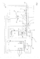
- 1 generally indicates an apparatus for producing a fertilizer in pellet form useful in the agricultural, zootechnical and gardening fields, for treating farmlands.
- Apparatus 1 comprises a source 4 of a carrier F which is adapted to enable to form fertilizing pellets for creating, recovering, conserving and/or increasing the fertility of a farmland, in other words to correct the nutritional properties of the farmland for cultivating it with excellent crop yields.
- the carrier F can be alternatively fed to the dispenser, as described in the following, in a solid form (for example as powder, granules or pellets) and gradually liquefied as the mixing step advances inside the dispenser.
- carrier F is kept at a temperature such to be in a liquid form (generally, the carrier is in a solid form at the environment temperature, that is 25°C) and comprises at least one substance selected in the group of the following substances: sulphur, urea, ammonium nitrate, paraffin, natural resin, synthetic resin or a mixture thereof.
- urea-based and sulphur-based carriers are those mainly used for their chemical properties and their low cost.
- the fertilizing compositions must contain an additive such to absorb water/moisture and increase the volume in order to disgregate (by a mechanical action) at least partially the used fertilizing pellet.
- first reservoir 11 adapted to contain the carrier F in a liquid form.
- first reservoir 11 comprises, in a non limiting way, a silos having a substantially cylindrical shape and extending, in an operative condition of the same, along a vertical direction.
- first reservoir 11 comprises a container having a bottom wall having a circular profile, a side wall having a cylindrical shape perimetrally connected to the bottom wall, and an upper wall located at the top of the side wall.
- first reservoir 11 is provided with a heating device 15 configured to heat carrier F for keeping it at a temperature comprised between 70°C and 200°C, particularly comprised between 80°C and 180°C, still more particularly comprised between 90°C and 150°C.
- the heating device 15 is configured to keep carrier F at a liquid form and enable to manage and moving it outside reservoir 11.
- Figure 1 represents, in a non-limiting way, an arrangement in which the heating device 15 is associated, in a non-limiting way, to the side wall of reservoir 11.
- device 15 can be associated to the bottom wall and/or upper wall of reservoir 11 (such configuration is non illustrated in the attached figures).
- carrier source 4 could consist in any other element adapted to supply a predetermined quantity of carrier in a liquid form.
- first reservoir 11 comprises at least one exit 11a advantageously located on the bottom wall of the latter, and which is configured to enable the carrier F to exit the reservoir 11.
- Exit 11a is hydraulically connected to a first supply line 2: the latter being adapted to enable the carrier F to be withdrawn from the first reservoir 11 and to discharge the same inside a dispenser 6 (dispenser 6 will be better described in the following).
- supply line 2 extends from an inlet 2a at which there is a connector 29 adapted to enable the hydraulic coupling of the first supply line 2 to the first reservoir 11, particularly the exit 11a of the first reservoir 11 to the inlet 2a of the first supply line 2.
- the first supply line 2 is provided with at least one pump 13, for example a geared pump, configured to enable to withdraw the carrier F from the first reservoir 11 and send the same to the dispenser 6.
- a preferred condition of apparatus 1 comprising, in a non-limiting way, a volumetric meter 19 operative on the first supply line 2: the meter 19 enabling to monitor the flow rate (quantity) of carrier F exiting from the first reservoir 11 and flowing through the first supply line 2.
- the volumetric meter 19 is positioned, in a non-limiting way, downstream the pump 13; however there is the possibility of positioning (or omitting) the volumetric meter 19 upstream the pump 13.
- the first supply line 2 further comprises an exit 2b hydraulically connected to the dispenser 6 and which enables to introduce into the latter the liquid carrier F coming from the first reservoir 11.
- the apparatus 1 further comprises at least one further source 5 of at least one additive A in a granular or powdery form.
- additive A is designed to provide suitable chemical-physical properties to the pellets, such as fertilizing, amending properties, etcetera.
- additive A comprises at least one compound selected in the group of the following compounds: clay, urea, sodium sulphates, potassium, calcium, ammonium, sodium phosphates, sodium carbonates, wood ash, coal, wood shavings, vegetal masses, starches, and obviously mixtures thereof.
- Reservoir 12 comprises, in a non-limiting way, a silos which, as for the reservoir 11, comprises a bottom wall, a side wall, and an upper wall.
- apparatus 1 comprises valves 14 associated to reservoir 12 and particularly arranged at the exit 12a of the latter. Valves 14 are configured to enable to supply additive A exiting said second reservoir 12.
- apparatus 1 comprises, in a non-limiting way, a dispenser 25 associated to the supply line 3, particularly positioned between the inlet and exit 3a, 3b of the same supply line 3; dispenser 25 is formed for example by a hopper adapted to receive additive A exiting the reservoir 12 and supply into the dispenser 6.
- dispenser 25 enables to control with high accuracy the quantity of additive A to be mixed with carrier F and consequently facilitates the control of the fertilizing pellets composition.
- a gravimetric-type dispenser can be used.
- the exit 12a of reservoir 12 is connected (in fluid communication with) to a second supply line 3: the latter being adapted to enable to withdraw the additive A from reservoir 12 and introduce the same in the dispenser 6 (dispenser 6 will be better described in the following). More specifically, supply line 3 extends from an inlet 3a, in communication with the exit 12a of reservoir 12, to an exit 3b communicating with dispenser 6.
- apparatus 1 comprises a dispenser 6 connected to the first and second supply lines 2, 3 and configured to receive carrier F and additive A.
- dispenser 6 is configured to move carrier F and additive A along an advancement direction 10 and simultaneously enable to mix them.
- the mixture of carrier F and additive A enables to form a fertilizing dispersion C which will then constitute the fertilizing pellets.
- apparatus 1 is configured to continuously send the carrier F and additive A to the dispenser 6 which continuously mixes and moves the liquid carrier F and additive A: dispenser 6 is configured to form the fertilizing dispersion C during the movement of the carrier F and additive A along the movement direction 10 for enabling to continuously supply the fertilizing dispersion C from the dispenser 6.
- Dispenser 6 comprises a mixing element 30 configured to mix the carrier F and additive A simultaneously with the continuous advancement step.
- mixing element 30 comprises, in a non-limiting way, an extruder 15 having a prevailing extension direction and extending between a first and second ends 31, 32.
- the movement of carrier F and additive A occurs along the advancement line 10 which has a direction starting from the first end 31 pointing to the second end 32 of the extruder 15.
- the dispenser 6 comprises a first and second inlets 6a, 6b fluidically communicating respectively with the exits 2b, 3b of the first and second supply lines 2, 3. Indeed, inlets 6a, 6b enable to introduce the carrier F and additive A in the extruder 15 through the supply lines 2, 3.
- dispenser 6 besides moving the carrier F and additive A, is configured to enable to mix them.
- first and second inlets 6a, 6b are advantageously located at a first half of the extruder 15 receiving said first end 31.
- First inlet 6a is positioned between the first and second ends 31, 32 of the latter, particularly at the center line of the extruder 15.
- Second inlet 6b is advantageously positioned at the first end 31, advantageously downstream the first inlet.
- the additive A inlet is positioned upstream the inlet of the liquid carrier F.
- Introducing the additive A in a granular or powdery form upstream the introduction of the liquid carrier F enables to substantially define a solid plug formed by the granular or powdery additive which is pushed by the dispenser to the exit of the latter.
- the introduction of the liquid carrier from the first inlet enables the latter to be mixed with the solid plug advancing from an exit 6c of the dispenser 6 to form said fertilizing dispersion C.
- carrier F and additive A in the first half of the extruder 15 enables the latter to perform a correct mixing during the movement of the carrier and additive in the direction of the second end 32 for forming the fertilizing dispersion C.
- dispenser 6 further comprises an exit 6c located at the second end 32: the exit 6c being adapted to enable to eject the fertilizing dispersion C outside the extruder 15.
- the exit area of the extruder has a throttling 33 adapted to receive the fertilizing dispersion and increase the pressure before its ejection.
- a nozzle 34 communicating with the throttling 33 has a passage cross-section smaller than the passage cross-section of the extruder substantially at the first and second inlets 6a, 6b.
- Nozzle 34 receives the compressed dispersion C and enables its ejection, particularly nozzle 34 defines the exit 6c of dispenser 6.
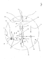
- Extruder 15 has Internally at least one helix or screw (for example shown in Figure 3 ) adapted to rotate inside the extruder 15 around an axis parallel to the prevailing extension direction of the extruder itself: the rotation of the screw or helix enables the extruder 16 to move (push) carrier F (entering from the first inlet 6a) and additive A (entering from the second inlet 6b) along the advancement line 10 and simultaneously enables to mix them.
- a single-screw extruder has been shown in a non-limiting way.
- the extruder 15 can comprise one or more pushing elements (screws or helixes) and define for example a twin--screw element.
- the dispenser 6 advantageously comprises a motor 24 operating the screw or helix adapted to enable its rotation.
- the rotation of the helix or screw 30 drives the dispersion C to the throttling 33 (compression of dispersion C) and then inside the nozzle 34 to be then ejected.
- apparatus 1 further comprises a pelletizer 7 arranged at the exit 6c of dispenser 6; pelletizer 7 is configured to continuously receive the fertilizing dispersion C exiting the nozzle 34 and (also continuously) form fertilizing pellets.
- Pelletizer 7 comprises, in a non-limiting way, a roll adapted to rotate around an axis orthogonal to the advancement line 10. A plurality of ejection nozzles present on the outer surface of the roll enable to expel the fertilizing dispersion C which, exiting the dispenser 6, is introduced into the pelletizer drum. As previously mentioned, dispersion C exiting the dispenser 6 is in a liquid form.
- the drops of the liquid dispersion exiting the pelletizer nozzles are suitably deposited, according to desired quantities and size on a conveyor belt adapted to cool the drops in order to solidify them, in other words they will have a pellet form.
- Apparatus 1 can comprise an aspirator 20 substantially positioned at the exit 6c of the dispenser 6; aspirator 20 is configured to enable the withdrawal of gasses and/or vapors generated during the ejection of the fertilizing dispersion C from the dispenser 6.
- the aspirator 20 comprises at least one collecting hood 21 positioned at the exit 6c of dispenser 6 and adapted to contain the gasses and/or vapors generated during the expulsion of the fertilizing dispersion from said dispenser 6.
- Hood 21 is in fluid communication with at least one discharge line 22 adapted to enable to withdraw and then eject the gasses collected by hood 21.
- the withdrawal and ejection of the gasses is ensured by the presence of at least one ejection device 23 (for example a fan) operative on the discharge line 22 and configured to direct the gasses and/or vapors from collecting hood 21 into the discharge line 22 for ejecting them.
- at least one ejection device 23 for example a fan
- apparatus 1 comprises at least one conveyor belt 8 adapted to receive discrete liquid quantities of the liquid fertilizing dispersion which will form the pellets, cool the latter so that they can be converted from the liquid or semi-liquid form to the solid form and moving them along an exit line 16.
- Conveyor belt 8 ends with a distributor 26 adapted to guide the expulsion of the solidified pellets from the belt 8 itself.
- Apparatus 1 further comprises a cooling device (not shown in the attached figures) associated to the conveyor belt 8; the cooling device, such as a series of sprinkles spraying a refrigerating liquid (for example water) operating on the bottom surface of the conveyor belt, is configured to lower the temperature of the fertilizing dispersion C exiting the dispenser 6, particularly it enables to take the pellets moving on the conveyor belt to a temperature comprised between 20°C and 70°C, still more particularly comprised between 20°C and 50°C.
- a cooling device such as a series of sprinkles spraying a refrigerating liquid (for example water) operating on the bottom surface of the conveyor belt, is configured to lower the temperature of the fertilizing dispersion C exiting the dispenser 6, particularly it enables to take the pellets moving on the conveyor belt to a temperature comprised between 20°C and 70°C, still more particularly comprised between 20°C and 50°C.
- a practical example of the cooling device can be represented by a water circuit adapted to cool down the belt 8 on which the pellets are moved: the belt cooling enables to cool down also the pellets contacting the latter with a consequent formation of pellets in the solid state.
- a further example of the cooling device can be represented by a blowing system positioned above the belt 8: the blowing system generates a cool air flow adapted to hit the pellets moving on belt 8.
- the quantity of carrier F and additive A sent by the respective sources 4, 5 enables to define the ratio between carrier F and additive A present in the fertilizing dispersion C and consequently enables to define the different properties of the pellets. More specifically, the fertilizing dispersion C has a percentage of carrier F greater than 70%, particularly greater than 80%, still more particularly greater than 85%. Referring to the concentrations of additive A, this is present in the dispersion with a percentage greater than 2%, particularly greater than 10%, still more particularly greater than 15%.
- apparatus 1 which is further provided with at least one bypass line 17 (shown for example in Figures 1 and 2 ) hydraulically connected to the first supply line 2 and configured to directly supply carrier F to pelletizer 7 by bypassing the dispenser 6.
- apparatus 1 is provided with at least one shut-off element 18 positioned in the first supply line 2 upstream the exit 2b of the latter; shut-off element 18 being in fluid communication with both the first supply line 2 and bypass line 17.
- the shut-off element 18 is configured to define a normal operative condition wherein this condition enables the carrier to pass through the overall supply line 2 to the dispenser 6 while it shuts off the passage of carrier F thorough the bypass line 17.
- the shut-off element 18 is further configured to define a bypass condition wherein it prevents carrier F to reach dispenser 6 while it enables the fluid to pass through the bypass line 17.
- the shut-off element 18 can comprise a manual valve or a three-way solenoid valve.
- control unit 9 which is connected to at least one among the pump 13, batcher 14 and dispenser 6.
- Control unit 9 is operative at least on said pump 13 and is configured to drive the latter in order to control the flow rate of the liquid carrier F to be sent to the dispenser 6.
- the flow rate control of the solution enables to control the concentration of the latter in the pellets.
- control unit 9 drives the pump 13 and checks by the meter the actual supply of carrier F. By this check, control unit 9 can continuously set the pump 13 based on measurements performed by the meter: in this way, control unit 9 enables an optimal management with reference to the carrier F quantity to be sent to the dispenser 6.
- Control unit 9 as represented in Figure 1 , can be further connected also to the shut-off element 18 and configured to command the latter to position itself in the normal operative condition or bypass condition.
- control unit 9 is at least also connected to the gravimetric batcher 25 and is configured to drive the latter in order to manage the additive A quantity to be sent to dispenser 6: in this way the control unit manages the additive concentration present in pellets.
- Control unit 9 is further connected to dispenser 6 in order to enable to manage the flow rate of the fertilizing dispersion C to be sent to the pelletizer 7. Particularly, control unit 9 is connected to the motor 24 adapted to control the rotation speed of the helix or worm: by the management of motor 24, control unit enables to drive the rotation speed of the helix or screw with a consequent control of the advancement speed of dispersion C.
- control unit 9 is further connected to the pelletizer 7 and belt 8. Indeed, based on the ejection speed of dispersion C, control unit 9 manages the speed of formation of pellets and the transport speed of belt 8.
- control unit 9 can be further connected to the aspirator 20, distributor 26 in order to manage and control respectively the operation of aspirator and the pellets ejection.
- Figure 1 represents, in a non limiting way, a first embodiment of apparatus 1 which is formed by just one dispenser 6 supplied by just one first and second supply lines 2, 3.
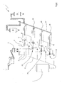
- Figure 2 represents a practical variant consisting of a plurality of supply lines 2, 3 adapted to supply several dispensers 6.
- the embodiment of Figure 2 schematically shows an apparatus 1 comprising several pellet production lines 35. It is possible to configure the production lines 35 so that each of them supplies pellets having different concentrations of carrier F and/or additive A.
- distributor 26 of each production line 35 supplies a switching belt 27 configured to collect pellets exiting each production line 35 and supplies the latter to different collecting reservoirs 28.
- the process comprises a first step of collecting a certain quantity of carrier F in the first reservoir 11.
- the carrier F inside the first reservoir 11 is heated by a heating device 15 and is taken to a temperature comprised between 70°C and 200°C, particularly comprised between 80°C and 180°C, still more particularly comprised between 90°C and 150°C. Heating the carrier F heating enables to make and keep it in the liquid state so that said solution F can be managed in the other process steps.
- the process provides to continuously supply, through the first supply line 2, the liquid solution F by the operation of pump 13 which enables to withdraw said carrier F from first reservoir 11 (first source 4) and (continuously) supply it to the dispenser 6 through the first inlet 6a.
- the pump is configured to continuously supply a carrier F flow rate greater than 7,000 kg/hr, particularly comprised between 9,000 kg/hr and 10,000 kg/hr.
- the process provides to continuously supply the additive A to said dispenser 6 through the second supply line 3.
- the supply step of the additive A provides to operate the valves 14 and gravimetric batcher 25 which enables to withdraw said additive A from second reservoir 12 (second source 5) and (continuously) supply it to the dispenser 6 through the second inlet 6b.
- batcher 25 enables to continuously send to the dispenser a quantity of additive A greater than 1,800 kg/hr, particularly comprised between 2,000 kg/hr and 2,400 kg/hr.
- second inlet 6b of additive A is upstream the first inlet 6a of the carrier; the process therefore provides to introduce the additive upstream the carrier.
- introduction sequence enables to form a solid plug of granular or powdery additive upstream the first inlet 6a.
- the additive A solid plug is pushed by the mixing element in the direction of the exit 6c of the dispenser.
- the carrier introduction through the first inlet positioned downstream the second inlet enables the carrier to hit the solid plug in order to form the fertilizing dispersion C.
- the additive a solid plug of granular or powdery material
- Carrier F and additive A in the dispenser 6 are continuously moved to the exit 6c of the latter along the movement direction 10: the movement is generated by the operation of motor 24 which puts in rotation the helix or screw 30.
- dispenser 6 mixes the latter to obtain the fertilizing dispersion C.
- the helix or screw 30 pushes the fertilizing dispersion C through the throttling 33 from where the dispersion is compelled to pass through the nozzle 34. Indeed, dispersion C is continuously moved inside the dispenser 6 and ejected, still continuously, through the exit 6c.
- the process enables to continuously supply a quantity of the fertilizing dispersion C greater than 8,000 kg/hr, particularly comprised between 11,000 kg/hr and 15,000 kg/hr.
- concentrations of the carrier F and additive A in the dispersion and consequently in the pellets vary as a function of the quantities of the same.
- the dispersion C, exiting the dispenser 6, has a percentage of carrier F greater than 70%, particularly greater than 80%, still more particularly greater than 85%.
- the concentration of additive A present in the fertilizing dispersion C exiting the dispenser 6, is greater than 2%, particularly greater than 10%, still more particularly greater than 15%.
- the process can comprise, in a non-limiting way, a step of sucking said gasses or vapors from the area where the dispersion C exits.
- the process provides a step of turning on the ejection device 23 (for example a fan) which is in communication with the discharge line 22 which in turn is connected to the collecting hood 21.
- the gasses and/or vapors generated when the dispersion C exits the dispenser 6, are contained and collected by the hood 21.
- the operation of the device 23 enables to drive said gasses inside the discharge line 22 and then they are ejected from the same device 23.
- the sucking step is performed in order to take the gasses and/or vapors generated by the dispersion C ejection step, far from the production area.
- the fertilizing dispersion C is generally formed by solutions or chemical compounds which can generate irritant gasses and/or vapors or anyway be removed from the work area: the removal of the gasses enables to keep safe the production site and in optimal working conditions.
- the dispersion C exiting the dispenser 6 is continuously sent to the pelletizer 7 which is configured to enable the formation of pellets formed by said fertilizing dispersion C.
- pelletizer 7 collects the fertilizing dispersion C continuously arriving from the dispenser and manufactures pellets on the conveyor belt.
- the step of pelletizing dispersion C is per se known and can be performed by different types of pelletizing units or pelletizers 7 and therefore will be not further explained.
- Pelletizer 7 continuously manufactures a plurality of dispersion C pellets which are deposited on belt 8 moving the pellets along the exit line 16 and to the distributor 26.
- the pellets moving on belt 8 are cooled down and taken to the solid state.
- the process enables to continuously produce a number of fertilizing pellets greater than 40,000,000 pellets/hr, particularly greater than 42,000,000 pellets/hr, still more particularly greater than 43,000,000 pellets/hr.
- the described process refers, in a non-limiting way, to just one production line 35, in other words to a process using just one dispenser 6 provided with only two supply lines 2 and 3.
- first and second supply lines 2 and 3 adapted to supply several dispensers 6 (condition shown in Figure 2 ).
- Each of said lines 2, 3 can be supplied with different flow rates of the carrier F or additive A so that each dispenser 6 can supply different pellets (different concentrations of the solution F and additive A).
- the process can provide the presence of a control unit 9 which enables, in a non-limiting way, to monitor and manage the overall process.
- the method and the plant, as described, can be obviously used for producing any kind of fertilizer in pellet form.
- the pellet fertilizer comprises a plurality of discrete elements or pellets having a shape and size which are almost similar and have the same composition.
- the weight of at least 90% of the pellets of fertilizer is less than 100 gr, particularly less than 80 gr, still more particularly less than 50 gr.
- Each pellet is substantially formed by a carrier F comprising at least one of the following components: sulphur, urea, ammonium nitrate, paraffin, natural resin, synthetic resin, and it is present in the dispersion in percentage by weight not less than 70% (the percentage by weight of the carrier (F) is generally greater than 80%), particularly greater than 85%).
- a carrier F comprising at least one of the following components: sulphur, urea, ammonium nitrate, paraffin, natural resin, synthetic resin, and it is present in the dispersion in percentage by weight not less than 70% (the percentage by weight of the carrier (F) is generally greater than 80%), particularly greater than 85%).
- composition then provides the presence of at least one additive A homogeneously dispersed in the carrier F; additive A comprises at least one substance adapted to perform a disgregating mechanical function of the pellet, for example in the presence of water or moisture.
- the carrier which at a room temperature (for example 25°C) is in a solid state, is substantially insoluble in water, it is necessary to add a component which causes its disgregation, particularly by a mechanical-type action.
- the more interesting carriers are sulphur or urea.
- the specific weight of carrier F, when consists of urea is greater than 1.3 kg/dm 3
- when consists of sulphur is greater than 1.9 kg/dm 3 .
- the substance adapted to perform the disgregating mechanical function of the pellet in the presence of rain or irrigation comprises vegetal fibers.
- vegetal fibers Illustratively, it is possible to use wood, wood shavings or anyway wood-based waste materials, vegetal masses, starches, stubbles and/or combinations thereof.
- the substance adapted to perform a disgregating mechanical function of the pellet is dispersed in the pellet in a particulate form, whose particles have a granulometry greater than 50 microns and less than 150 microns, particularly comprised between 80 and 120 microns.
- this substance absorbs water and increases the volume. Since this substances are intimately dispersed in the pellet, they cause the disgregation of the fertilizing pellet so that the components can be used for crop farming.
- the specific weight of a substance adapted to perform a disgregating mechanical function of the pellet is less than 1.7 kg/dm 3 , particularly less than 1.5 kg/dm 3 .
- the substance adapted to perform a disgregating mechanical function of the pellet is present in percentage greater than 2% by weight, but less than 10% by weight, and particularly less than 70% by weight.
- the use of vegetal fibers having a low weight enables to reduce the percentage of such components against a possible increment of other additives, particularly micronutrients, as explained in the following.
- the additive can comprise more or less other components such as micronutrients or sanitizing elements.
- the percentage by weight of the additive A is generally greater than 10% and particularly greater than 15% and is in percentage by weight less than 20% and particularly greater than 16% by weight.
- the possible micronutrient substance/substances comprises/comprise urea, sodium sulphates, potassium, calcium, ammonium, sodium phosphates, sodium carbonates, wood ash or combinations thereof and makes/make up in percentage by weight, less than 15%, more particularly less than 12% of the overall weight of the pellet.
- the micronutrient substance is present in percentage by weight greater than 5%, more particularly greater than 8% by weight.
- the additive (A) can comprise at least one sanitizing substance, such as coal.
- the above described apparatus is configured to enable to mix the carrier F and additive A inside the dispenser 6 simultaneously with the displacement of the latter along the advancement line 10 in an extremely quick and effective way.
- the reduced size of the apparatus 1 and the small number of components, besides enabling to reduce the production time, enables to make extremely economical the overall production system and make easier its maintenance and management.
- the process and apparatus are extremely versatile so that they enable to modify the compositions of the fertilizer substantially in real time and without substantial waste.
- composition enables to obtain fertilizing pellets at a cost below than the ones commercially available and wherein the percentage of micronutrients, usually not greater than 5%, can be taken to a percentage of about 10%.
Landscapes
- Chemical & Material Sciences (AREA)
- Organic Chemistry (AREA)
- Chemical Kinetics & Catalysis (AREA)
- Life Sciences & Earth Sciences (AREA)
- Pest Control & Pesticides (AREA)
- Inorganic Chemistry (AREA)
- Fertilizers (AREA)
Priority Applications (2)
| Application Number | Priority Date | Filing Date | Title |
|---|---|---|---|
| RS20200075A RS59856B1 (sr) | 2012-10-02 | 2013-09-18 | Postupak i uređaj za proizvodnju đubriva u obliku peleta |
| EP19204439.4A EP3636624B1 (de) | 2012-10-02 | 2013-09-18 | Verfahren und vorrichtung zur herstellung eines düngemittels in pelletform |
Applications Claiming Priority (1)
| Application Number | Priority Date | Filing Date | Title |
|---|---|---|---|
| IT001648A ITMI20121648A1 (it) | 2012-10-02 | 2012-10-02 | Processo ed apparecchiatura per la produzione di fertilizzante in pastiglie |
Related Child Applications (1)
| Application Number | Title | Priority Date | Filing Date |
|---|---|---|---|
| EP19204439.4A Division EP3636624B1 (de) | 2012-10-02 | 2013-09-18 | Verfahren und vorrichtung zur herstellung eines düngemittels in pelletform |
Publications (3)
| Publication Number | Publication Date |
|---|---|
| EP2716620A2 true EP2716620A2 (de) | 2014-04-09 |
| EP2716620A3 EP2716620A3 (de) | 2017-12-06 |
| EP2716620B1 EP2716620B1 (de) | 2019-11-06 |
Family
ID=47190026
Family Applications (2)
| Application Number | Title | Priority Date | Filing Date |
|---|---|---|---|
| EP19204439.4A Active EP3636624B1 (de) | 2012-10-02 | 2013-09-18 | Verfahren und vorrichtung zur herstellung eines düngemittels in pelletform |
| EP13184892.1A Active EP2716620B1 (de) | 2012-10-02 | 2013-09-18 | Verfahren und Vorrichtung zur Herstellung von pelletformige Düngemittel |
Family Applications Before (1)
| Application Number | Title | Priority Date | Filing Date |
|---|---|---|---|
| EP19204439.4A Active EP3636624B1 (de) | 2012-10-02 | 2013-09-18 | Verfahren und vorrichtung zur herstellung eines düngemittels in pelletform |
Country Status (4)
| Country | Link |
|---|---|
| EP (2) | EP3636624B1 (de) |
| ES (1) | ES2768094T3 (de) |
| IT (1) | ITMI20121648A1 (de) |
| RS (1) | RS59856B1 (de) |
Cited By (14)
| Publication number | Priority date | Publication date | Assignee | Title |
|---|---|---|---|---|
| WO2016073399A1 (en) * | 2014-11-04 | 2016-05-12 | The Procter & Gamble Company | Apparatus and process for forming particles |
| CN105618741A (zh) * | 2016-03-22 | 2016-06-01 | 石家庄荣信科技有限公司 | 一种自动粉末冶金给料机 |
| WO2018054258A1 (zh) * | 2016-09-20 | 2018-03-29 | 五洲丰农业科技有限公司 | 肥料生产系统 |
| CN108854846A (zh) * | 2018-06-27 | 2018-11-23 | 杭州桥福科技有限公司 | 一种高效环保型秸秆加工颗粒机 |
| US10465048B2 (en) | 2017-01-09 | 2019-11-05 | The Procter & Gamble Company | Apparatus and process for forming particles |
| CN110917991A (zh) * | 2019-12-12 | 2020-03-27 | 李智薇 | 一种药丸生产用全自动无菌制粒机 |
| US11040920B2 (en) | 2017-12-15 | 2021-06-22 | Innovations For World Nutrition Llc | Fertilizer and plant growth promoter to increase plant yield and method of increasing plant yield |
| US11192830B2 (en) | 2020-04-15 | 2021-12-07 | Innovations for World Nutrition, LLC | Seed coating to promote plant growth and method of increasing plant yield |
| WO2022079397A1 (fr) * | 2020-10-16 | 2022-04-21 | Institut National Polytechnique De Toulouse | Produit pour l'agriculture, et procédé de préparation |
| US11358909B2 (en) | 2020-04-15 | 2022-06-14 | Innovations for World Nutrition, LLC | Fertilizer containing a seed grind and a method of using the fertilizer to enhance plant growth |
| US11634366B2 (en) | 2020-04-15 | 2023-04-25 | Innovations for World Nutrition, LLC | Plant growth enhancer using carbon dioxide to increase plant yield and method of increasing plant yield |
| US11787749B2 (en) | 2020-04-15 | 2023-10-17 | Innovations for World Nutrition, LLC | Fertilizer and plant growth promoter to increase plant yield and method of increasing plant yield |
| CN118058021A (zh) * | 2024-04-24 | 2024-05-24 | 蒙草生态环境(集团)股份有限公司 | 一种适用于沙地治理的生态包配置系统及其配置方法 |
| US12162809B2 (en) | 2020-04-15 | 2024-12-10 | Innovations for World Nutrition, LLC | Fertilizer using carbon dioxide to increase plant yield and method of increasing plant yield |
Families Citing this family (3)
| Publication number | Priority date | Publication date | Assignee | Title |
|---|---|---|---|---|
| CN109126633B (zh) * | 2018-08-29 | 2023-09-15 | 山东华鲁恒升化工股份有限公司 | 高成品率的尿素造粒塔 |
| US12486206B2 (en) | 2020-04-15 | 2025-12-02 | Innovations for World Nutrition, LLC | Seed coating to promote plant growth and method of increasing plant yield |
| EP4001246A1 (de) | 2020-11-20 | 2022-05-25 | Clariant Produkte (Deutschland) GmbH | Vinassehaltiges düngemittel |
Citations (4)
| Publication number | Priority date | Publication date | Assignee | Title |
|---|---|---|---|---|
| US20070131381A1 (en) | 2005-11-08 | 2007-06-14 | Santrade Ltd. | Method for belt conditioning in pelletizing plants, method for pelletizing urea and pelletizing plant |
| US7700012B2 (en) | 2005-04-18 | 2010-04-20 | Dsm Ip Assets B.V. | Process for the production of urea-comprising particles |
| US20100288005A1 (en) | 2007-12-11 | 2010-11-18 | Hans-Kurt Schromm | Method and drop former for producing tablets and method for producing a sulfurous fertilizer |
| WO2012007331A1 (de) | 2010-07-16 | 2012-01-19 | Sandvik Materials Technology Deutschland Gmbh | Verfahren zum herstellen von ammoniumnitrat enthaltenden pastillen |
Family Cites Families (13)
| Publication number | Priority date | Publication date | Assignee | Title |
|---|---|---|---|---|
| BE513049A (de) * | 1951-07-24 | |||
| FR1356105A (fr) * | 1963-05-03 | 1964-03-20 | Duengemittel Technik A G | Procédé et installation pour la fabrication de produits granulés |
| BE803102Q (en) * | 1968-06-06 | 1973-12-03 | Duengemittel Technik A G | Granulation of powders esp fertilisers - including pregranulation step using water vapour |
| CA1129227A (en) * | 1980-02-29 | 1982-08-10 | Canadian Superior Oil Ltd. | Sulphur-clay prills |
| US4569859A (en) * | 1984-07-10 | 1986-02-11 | Sulpetro Limited | Process for forming prill for sulphur and bentonite |
| US5443764A (en) * | 1987-07-01 | 1995-08-22 | Ici Australia Operations Propietary Limited | Water-dispersible granules |
| US5749936A (en) * | 1996-06-07 | 1998-05-12 | A.J. Sackett And Sons Company | Method of producing dry granular fertilizer and soil amendments using clay slurry and dry chemicals |
| DE19706433A1 (de) | 1997-02-19 | 1998-08-20 | Glatt Ingtech Gmbh | Verfahren zur Herstellung von Schmelzsuspensionen, Emulsionen oder Lösungen |
| IT1295099B1 (it) * | 1997-08-28 | 1999-04-30 | Gian Maria Bercelli | Processo per la produzione di concimi granulari e relativo impianto di granulazione. |
| US6499984B1 (en) | 2000-05-22 | 2002-12-31 | Warner-Lambert Company | Continuous production of pharmaceutical granulation |
| EP1195365A1 (de) | 2000-09-21 | 2002-04-10 | Agra Dünger GmbH | Verfahren zur Herstellung von Methylenharnstoff-Polymeren |
| DE10122615A1 (de) * | 2001-05-10 | 2002-11-14 | Romonta Ceralith Gmbh | Anlage zur Herstellung von Granulaten aus biopolymeren und mineralischen Rohstoffen |
| US6749659B1 (en) * | 2001-10-09 | 2004-06-15 | Enersul, Inc. | Controlled release rate fertilizers and methods of making same |
-
2012
- 2012-10-02 IT IT001648A patent/ITMI20121648A1/it unknown
-
2013
- 2013-09-18 RS RS20200075A patent/RS59856B1/sr unknown
- 2013-09-18 EP EP19204439.4A patent/EP3636624B1/de active Active
- 2013-09-18 EP EP13184892.1A patent/EP2716620B1/de active Active
- 2013-09-18 ES ES13184892T patent/ES2768094T3/es active Active
Patent Citations (4)
| Publication number | Priority date | Publication date | Assignee | Title |
|---|---|---|---|---|
| US7700012B2 (en) | 2005-04-18 | 2010-04-20 | Dsm Ip Assets B.V. | Process for the production of urea-comprising particles |
| US20070131381A1 (en) | 2005-11-08 | 2007-06-14 | Santrade Ltd. | Method for belt conditioning in pelletizing plants, method for pelletizing urea and pelletizing plant |
| US20100288005A1 (en) | 2007-12-11 | 2010-11-18 | Hans-Kurt Schromm | Method and drop former for producing tablets and method for producing a sulfurous fertilizer |
| WO2012007331A1 (de) | 2010-07-16 | 2012-01-19 | Sandvik Materials Technology Deutschland Gmbh | Verfahren zum herstellen von ammoniumnitrat enthaltenden pastillen |
Cited By (20)
| Publication number | Priority date | Publication date | Assignee | Title |
|---|---|---|---|---|
| US9763860B2 (en) | 2014-11-04 | 2017-09-19 | The Procter & Gamble Company | Apparatus and process for forming particles |
| WO2016073399A1 (en) * | 2014-11-04 | 2016-05-12 | The Procter & Gamble Company | Apparatus and process for forming particles |
| US10328000B2 (en) * | 2014-11-04 | 2019-06-25 | The Procter & Gamble Company | Apparatus and process for forming particles |
| CN105618741A (zh) * | 2016-03-22 | 2016-06-01 | 石家庄荣信科技有限公司 | 一种自动粉末冶金给料机 |
| EA036873B1 (ru) * | 2016-09-20 | 2020-12-30 | Учжоуфэн Эгрикалчурал Сайенс Энд Текнолоджи Ко., Лтд | Установка для производства удобрений |
| WO2018054258A1 (zh) * | 2016-09-20 | 2018-03-29 | 五洲丰农业科技有限公司 | 肥料生产系统 |
| US10465048B2 (en) | 2017-01-09 | 2019-11-05 | The Procter & Gamble Company | Apparatus and process for forming particles |
| US11040920B2 (en) | 2017-12-15 | 2021-06-22 | Innovations For World Nutrition Llc | Fertilizer and plant growth promoter to increase plant yield and method of increasing plant yield |
| CN108854846B (zh) * | 2018-06-27 | 2020-07-14 | 宋晴 | 一种高效环保型秸秆加工颗粒机 |
| CN108854846A (zh) * | 2018-06-27 | 2018-11-23 | 杭州桥福科技有限公司 | 一种高效环保型秸秆加工颗粒机 |
| CN110917991A (zh) * | 2019-12-12 | 2020-03-27 | 李智薇 | 一种药丸生产用全自动无菌制粒机 |
| US11192830B2 (en) | 2020-04-15 | 2021-12-07 | Innovations for World Nutrition, LLC | Seed coating to promote plant growth and method of increasing plant yield |
| US11358909B2 (en) | 2020-04-15 | 2022-06-14 | Innovations for World Nutrition, LLC | Fertilizer containing a seed grind and a method of using the fertilizer to enhance plant growth |
| US11634366B2 (en) | 2020-04-15 | 2023-04-25 | Innovations for World Nutrition, LLC | Plant growth enhancer using carbon dioxide to increase plant yield and method of increasing plant yield |
| US11787749B2 (en) | 2020-04-15 | 2023-10-17 | Innovations for World Nutrition, LLC | Fertilizer and plant growth promoter to increase plant yield and method of increasing plant yield |
| US12017964B2 (en) | 2020-04-15 | 2024-06-25 | Innovations for World Nutrition, LLC | Plant growth enhancer using carbon dioxide to increase plant yield |
| US12162809B2 (en) | 2020-04-15 | 2024-12-10 | Innovations for World Nutrition, LLC | Fertilizer using carbon dioxide to increase plant yield and method of increasing plant yield |
| WO2022079397A1 (fr) * | 2020-10-16 | 2022-04-21 | Institut National Polytechnique De Toulouse | Produit pour l'agriculture, et procédé de préparation |
| FR3115282A1 (fr) * | 2020-10-16 | 2022-04-22 | Institut National Polytechnique De Toulouse | Produit pour l’agriculture, et procede de preparation |
| CN118058021A (zh) * | 2024-04-24 | 2024-05-24 | 蒙草生态环境(集团)股份有限公司 | 一种适用于沙地治理的生态包配置系统及其配置方法 |
Also Published As
| Publication number | Publication date |
|---|---|
| EP3636624B1 (de) | 2025-01-08 |
| ITMI20121648A1 (it) | 2014-04-03 |
| EP2716620A3 (de) | 2017-12-06 |
| EP3636624A1 (de) | 2020-04-15 |
| EP3636624C0 (de) | 2025-01-08 |
| ES2768094T3 (es) | 2020-06-19 |
| EP2716620B1 (de) | 2019-11-06 |
| RS59856B1 (sr) | 2020-02-28 |
Similar Documents
| Publication | Publication Date | Title |
|---|---|---|
| EP2716620A2 (de) | Verfahren und Vorrichtung zur Herstellung von pelletformigem Düngemittel | |
| CN103804069B (zh) | 一种缓释肥料及其生产方法 | |
| CN1213964C (zh) | 熔融料浆低塔造粒生产颗粒多元复合肥料的方法及设备 | |
| CN101357859A (zh) | 粒状复合肥及其熔体料浆造粒方法 | |
| CN114874040B (zh) | 一种含有机质含硼掺混肥料、掺拌设备及制造方法 | |
| CN205152100U (zh) | 一种硝酸磷酸混合制取氮磷复合肥装置 | |
| CN216377969U (zh) | app肥的连续生产装置 | |
| CN115869890B (zh) | 磷酸三乙酯连续化生产设备和方法 | |
| CN105399455A (zh) | 一种利用化工尾气生产复合肥的系统及方法 | |
| CN1064657C (zh) | 硝铵复合肥的生产方法和设备 | |
| CN101152622B (zh) | 造粒方法 | |
| CN211255764U (zh) | 一种硝硫铵复合肥的生产装置 | |
| CN209885716U (zh) | 一种水溶复合肥生产装置 | |
| CN117482815B (zh) | 一种高浓度无机水溶肥料制备设备 | |
| CN113912423A (zh) | app肥的连续生产方法及装置 | |
| CN113929541A (zh) | 一步法腐植酸水溶肥连续生产工艺 | |
| CN106518528A (zh) | 一种黄植酸钾马铃薯专用肥及其制备方法 | |
| CN110818475B (zh) | 一种硝硫铵复合肥的生产方法及生产装置 | |
| CN104072246B (zh) | 一种含硝态氮的复合肥的喷浆造粒生产工艺 | |
| ITMI20121649A1 (it) | Processo per la produzione di fertilizzante in pastiglie e fertilizzante in pastiglie cosi¿ prodotto | |
| US20100263420A1 (en) | Process for the continuous granulation of fertilizers | |
| CA2357367A1 (en) | Method for producing methylene urea polymers | |
| CN113511944B (zh) | 一种水溶肥及其生产设备 | |
| CN213761616U (zh) | 一种硼镁肥加料搅拌装置 | |
| CN203904235U (zh) | 一种半化成测土配方肥生产系统 |
Legal Events
| Date | Code | Title | Description |
|---|---|---|---|
| PUAI | Public reference made under article 153(3) epc to a published international application that has entered the european phase |
Free format text: ORIGINAL CODE: 0009012 |
|
| AK | Designated contracting states |
Kind code of ref document: A2 Designated state(s): AL AT BE BG CH CY CZ DE DK EE ES FI FR GB GR HR HU IE IS IT LI LT LU LV MC MK MT NL NO PL PT RO RS SE SI SK SM TR |
|
| AX | Request for extension of the european patent |
Extension state: BA ME |
|
| RAP1 | Party data changed (applicant data changed or rights of an application transferred) |
Owner name: SBS STEEL BELT SYSTEMS S.R.L. |
|
| PUAL | Search report despatched |
Free format text: ORIGINAL CODE: 0009013 |
|
| AK | Designated contracting states |
Kind code of ref document: A3 Designated state(s): AL AT BE BG CH CY CZ DE DK EE ES FI FR GB GR HR HU IE IS IT LI LT LU LV MC MK MT NL NO PL PT RO RS SE SI SK SM TR |
|
| AX | Request for extension of the european patent |
Extension state: BA ME |
|
| RIC1 | Information provided on ipc code assigned before grant |
Ipc: C05G 3/00 20060101AFI20171030BHEP Ipc: B01J 2/22 20060101ALI20171030BHEP Ipc: B01J 2/20 20060101ALI20171030BHEP |
|
| STAA | Information on the status of an ep patent application or granted ep patent |
Free format text: STATUS: REQUEST FOR EXAMINATION WAS MADE |
|
| RBV | Designated contracting states (corrected) |
Designated state(s): AL AT BE BG CH CY CZ DE DK EE ES FI FR GB GR HR HU IE IS IT LI LT LU LV MC MK MT NL NO PL PT RO RS SE SI SK SM TR |
|
| 17P | Request for examination filed |
Effective date: 20180315 |
|
| GRAP | Despatch of communication of intention to grant a patent |
Free format text: ORIGINAL CODE: EPIDOSNIGR1 |
|
| STAA | Information on the status of an ep patent application or granted ep patent |
Free format text: STATUS: GRANT OF PATENT IS INTENDED |
|
| INTG | Intention to grant announced |
Effective date: 20190503 |
|
| GRAS | Grant fee paid |
Free format text: ORIGINAL CODE: EPIDOSNIGR3 |
|
| GRAJ | Information related to disapproval of communication of intention to grant by the applicant or resumption of examination proceedings by the epo deleted |
Free format text: ORIGINAL CODE: EPIDOSDIGR1 |
|
| GRAL | Information related to payment of fee for publishing/printing deleted |
Free format text: ORIGINAL CODE: EPIDOSDIGR3 |
|
| STAA | Information on the status of an ep patent application or granted ep patent |
Free format text: STATUS: REQUEST FOR EXAMINATION WAS MADE |
|
| GRAR | Information related to intention to grant a patent recorded |
Free format text: ORIGINAL CODE: EPIDOSNIGR71 |
|
| STAA | Information on the status of an ep patent application or granted ep patent |
Free format text: STATUS: GRANT OF PATENT IS INTENDED |
|
| INTC | Intention to grant announced (deleted) | ||
| RIN1 | Information on inventor provided before grant (corrected) |
Inventor name: CALAMRA, RENATO Inventor name: VIRGILIO, GIANLUIGI |
|
| GRAA | (expected) grant |
Free format text: ORIGINAL CODE: 0009210 |
|
| STAA | Information on the status of an ep patent application or granted ep patent |
Free format text: STATUS: THE PATENT HAS BEEN GRANTED |
|
| INTG | Intention to grant announced |
Effective date: 20190909 |
|
| AK | Designated contracting states |
Kind code of ref document: B1 Designated state(s): AL AT BE BG CH CY CZ DE DK EE ES FI FR GB GR HR HU IE IS IT LI LT LU LV MC MK MT NL NO PL PT RO RS SE SI SK SM TR |
|
| REG | Reference to a national code |
Ref country code: GB Ref legal event code: FG4D |
|
| REG | Reference to a national code |
Ref country code: CH Ref legal event code: EP Ref country code: AT Ref legal event code: REF Ref document number: 1198553 Country of ref document: AT Kind code of ref document: T Effective date: 20191115 |
|
| REG | Reference to a national code |
Ref country code: IE Ref legal event code: FG4D |
|
| REG | Reference to a national code |
Ref country code: DE Ref legal event code: R096 Ref document number: 602013062474 Country of ref document: DE |
|
| REG | Reference to a national code |
Ref country code: CH Ref legal event code: NV Representative=s name: ING. ALESSANDRO GALASSI C/O PGA S.P.A., MILANO, CH |
|
| REG | Reference to a national code |
Ref country code: SE Ref legal event code: TRGR |
|
| REG | Reference to a national code |
Ref country code: LT Ref legal event code: MG4D |
|
| PG25 | Lapsed in a contracting state [announced via postgrant information from national office to epo] |
Ref country code: PT Free format text: LAPSE BECAUSE OF FAILURE TO SUBMIT A TRANSLATION OF THE DESCRIPTION OR TO PAY THE FEE WITHIN THE PRESCRIBED TIME-LIMIT Effective date: 20200306 Ref country code: LV Free format text: LAPSE BECAUSE OF FAILURE TO SUBMIT A TRANSLATION OF THE DESCRIPTION OR TO PAY THE FEE WITHIN THE PRESCRIBED TIME-LIMIT Effective date: 20191106 Ref country code: LT Free format text: LAPSE BECAUSE OF FAILURE TO SUBMIT A TRANSLATION OF THE DESCRIPTION OR TO PAY THE FEE WITHIN THE PRESCRIBED TIME-LIMIT Effective date: 20191106 Ref country code: PL Free format text: LAPSE BECAUSE OF FAILURE TO SUBMIT A TRANSLATION OF THE DESCRIPTION OR TO PAY THE FEE WITHIN THE PRESCRIBED TIME-LIMIT Effective date: 20191106 Ref country code: FI Free format text: LAPSE BECAUSE OF FAILURE TO SUBMIT A TRANSLATION OF THE DESCRIPTION OR TO PAY THE FEE WITHIN THE PRESCRIBED TIME-LIMIT Effective date: 20191106 Ref country code: NO Free format text: LAPSE BECAUSE OF FAILURE TO SUBMIT A TRANSLATION OF THE DESCRIPTION OR TO PAY THE FEE WITHIN THE PRESCRIBED TIME-LIMIT Effective date: 20200206 Ref country code: BG Free format text: LAPSE BECAUSE OF FAILURE TO SUBMIT A TRANSLATION OF THE DESCRIPTION OR TO PAY THE FEE WITHIN THE PRESCRIBED TIME-LIMIT Effective date: 20200206 |
|
| REG | Reference to a national code |
Ref country code: NL Ref legal event code: FP |
|
| REG | Reference to a national code |
Ref country code: GR Ref legal event code: EP Ref document number: 20200400266 Country of ref document: GR Effective date: 20200511 |
|
| PG25 | Lapsed in a contracting state [announced via postgrant information from national office to epo] |
Ref country code: HR Free format text: LAPSE BECAUSE OF FAILURE TO SUBMIT A TRANSLATION OF THE DESCRIPTION OR TO PAY THE FEE WITHIN THE PRESCRIBED TIME-LIMIT Effective date: 20191106 Ref country code: IS Free format text: LAPSE BECAUSE OF FAILURE TO SUBMIT A TRANSLATION OF THE DESCRIPTION OR TO PAY THE FEE WITHIN THE PRESCRIBED TIME-LIMIT Effective date: 20200306 |
|
| REG | Reference to a national code |
Ref country code: DE Ref legal event code: R026 Ref document number: 602013062474 Country of ref document: DE |
|
| PLBI | Opposition filed |
Free format text: ORIGINAL CODE: 0009260 |
|
| REG | Reference to a national code |
Ref country code: ES Ref legal event code: FG2A Ref document number: 2768094 Country of ref document: ES Kind code of ref document: T3 Effective date: 20200619 |
|
| PG25 | Lapsed in a contracting state [announced via postgrant information from national office to epo] |
Ref country code: AL Free format text: LAPSE BECAUSE OF FAILURE TO SUBMIT A TRANSLATION OF THE DESCRIPTION OR TO PAY THE FEE WITHIN THE PRESCRIBED TIME-LIMIT Effective date: 20191106 |
|
| 26 | Opposition filed |
Opponent name: IPCO GERMANY GMBH Effective date: 20200617 |
|
| PG25 | Lapsed in a contracting state [announced via postgrant information from national office to epo] |
Ref country code: EE Free format text: LAPSE BECAUSE OF FAILURE TO SUBMIT A TRANSLATION OF THE DESCRIPTION OR TO PAY THE FEE WITHIN THE PRESCRIBED TIME-LIMIT Effective date: 20191106 Ref country code: DK Free format text: LAPSE BECAUSE OF FAILURE TO SUBMIT A TRANSLATION OF THE DESCRIPTION OR TO PAY THE FEE WITHIN THE PRESCRIBED TIME-LIMIT Effective date: 20191106 Ref country code: CZ Free format text: LAPSE BECAUSE OF FAILURE TO SUBMIT A TRANSLATION OF THE DESCRIPTION OR TO PAY THE FEE WITHIN THE PRESCRIBED TIME-LIMIT Effective date: 20191106 Ref country code: RO Free format text: LAPSE BECAUSE OF FAILURE TO SUBMIT A TRANSLATION OF THE DESCRIPTION OR TO PAY THE FEE WITHIN THE PRESCRIBED TIME-LIMIT Effective date: 20191106 |
|
| REG | Reference to a national code |
Ref country code: AT Ref legal event code: MK05 Ref document number: 1198553 Country of ref document: AT Kind code of ref document: T Effective date: 20191106 |
|
| PLAX | Notice of opposition and request to file observation + time limit sent |
Free format text: ORIGINAL CODE: EPIDOSNOBS2 |
|
| PG25 | Lapsed in a contracting state [announced via postgrant information from national office to epo] |
Ref country code: SM Free format text: LAPSE BECAUSE OF FAILURE TO SUBMIT A TRANSLATION OF THE DESCRIPTION OR TO PAY THE FEE WITHIN THE PRESCRIBED TIME-LIMIT Effective date: 20191106 Ref country code: SK Free format text: LAPSE BECAUSE OF FAILURE TO SUBMIT A TRANSLATION OF THE DESCRIPTION OR TO PAY THE FEE WITHIN THE PRESCRIBED TIME-LIMIT Effective date: 20191106 |
|
| PG25 | Lapsed in a contracting state [announced via postgrant information from national office to epo] |
Ref country code: SI Free format text: LAPSE BECAUSE OF FAILURE TO SUBMIT A TRANSLATION OF THE DESCRIPTION OR TO PAY THE FEE WITHIN THE PRESCRIBED TIME-LIMIT Effective date: 20191106 Ref country code: AT Free format text: LAPSE BECAUSE OF FAILURE TO SUBMIT A TRANSLATION OF THE DESCRIPTION OR TO PAY THE FEE WITHIN THE PRESCRIBED TIME-LIMIT Effective date: 20191106 |
|
| PLBB | Reply of patent proprietor to notice(s) of opposition received |
Free format text: ORIGINAL CODE: EPIDOSNOBS3 |
|
| PG25 | Lapsed in a contracting state [announced via postgrant information from national office to epo] |
Ref country code: MC Free format text: LAPSE BECAUSE OF FAILURE TO SUBMIT A TRANSLATION OF THE DESCRIPTION OR TO PAY THE FEE WITHIN THE PRESCRIBED TIME-LIMIT Effective date: 20191106 |
|
| GBPC | Gb: european patent ceased through non-payment of renewal fee |
Effective date: 20200918 |
|
| REG | Reference to a national code |
Ref country code: BE Ref legal event code: MM Effective date: 20200930 |
|
| PG25 | Lapsed in a contracting state [announced via postgrant information from national office to epo] |
Ref country code: LU Free format text: LAPSE BECAUSE OF NON-PAYMENT OF DUE FEES Effective date: 20200918 |
|
| PG25 | Lapsed in a contracting state [announced via postgrant information from national office to epo] |
Ref country code: FR Free format text: LAPSE BECAUSE OF NON-PAYMENT OF DUE FEES Effective date: 20200930 |
|
| PG25 | Lapsed in a contracting state [announced via postgrant information from national office to epo] |
Ref country code: BE Free format text: LAPSE BECAUSE OF NON-PAYMENT OF DUE FEES Effective date: 20200930 Ref country code: GB Free format text: LAPSE BECAUSE OF NON-PAYMENT OF DUE FEES Effective date: 20200918 Ref country code: IE Free format text: LAPSE BECAUSE OF NON-PAYMENT OF DUE FEES Effective date: 20200918 |
|
| PG25 | Lapsed in a contracting state [announced via postgrant information from national office to epo] |
Ref country code: MT Free format text: LAPSE BECAUSE OF FAILURE TO SUBMIT A TRANSLATION OF THE DESCRIPTION OR TO PAY THE FEE WITHIN THE PRESCRIBED TIME-LIMIT Effective date: 20191106 Ref country code: CY Free format text: LAPSE BECAUSE OF FAILURE TO SUBMIT A TRANSLATION OF THE DESCRIPTION OR TO PAY THE FEE WITHIN THE PRESCRIBED TIME-LIMIT Effective date: 20191106 |
|
| PG25 | Lapsed in a contracting state [announced via postgrant information from national office to epo] |
Ref country code: MK Free format text: LAPSE BECAUSE OF FAILURE TO SUBMIT A TRANSLATION OF THE DESCRIPTION OR TO PAY THE FEE WITHIN THE PRESCRIBED TIME-LIMIT Effective date: 20191106 |
|
| PLBP | Opposition withdrawn |
Free format text: ORIGINAL CODE: 0009264 |
|
| PLBD | Termination of opposition procedure: decision despatched |
Free format text: ORIGINAL CODE: EPIDOSNOPC1 |
|
| REG | Reference to a national code |
Ref country code: DE Ref legal event code: R100 Ref document number: 602013062474 Country of ref document: DE |
|
| PLBM | Termination of opposition procedure: date of legal effect published |
Free format text: ORIGINAL CODE: 0009276 |
|
| 27C | Opposition proceedings terminated |
Effective date: 20220915 |
|
| P01 | Opt-out of the competence of the unified patent court (upc) registered |
Effective date: 20230528 |
|
| PGFP | Annual fee paid to national office [announced via postgrant information from national office to epo] |
Ref country code: ES Payment date: 20241021 Year of fee payment: 12 |
|
| PGFP | Annual fee paid to national office [announced via postgrant information from national office to epo] |
Ref country code: CH Payment date: 20241001 Year of fee payment: 12 |
|
| REG | Reference to a national code |
Ref country code: CH Ref legal event code: U11 Free format text: ST27 STATUS EVENT CODE: U-0-0-U10-U11 (AS PROVIDED BY THE NATIONAL OFFICE) Effective date: 20251001 |
|
| PGFP | Annual fee paid to national office [announced via postgrant information from national office to epo] |
Ref country code: DE Payment date: 20250926 Year of fee payment: 13 |
|
| PGFP | Annual fee paid to national office [announced via postgrant information from national office to epo] |
Ref country code: GR Payment date: 20250923 Year of fee payment: 13 |
|
| PGFP | Annual fee paid to national office [announced via postgrant information from national office to epo] |
Ref country code: TR Payment date: 20250909 Year of fee payment: 13 Ref country code: NL Payment date: 20250925 Year of fee payment: 13 Ref country code: IT Payment date: 20250922 Year of fee payment: 13 |
|
| PGFP | Annual fee paid to national office [announced via postgrant information from national office to epo] |
Ref country code: SE Payment date: 20250924 Year of fee payment: 13 |
|
| PGFP | Annual fee paid to national office [announced via postgrant information from national office to epo] |
Ref country code: RS Payment date: 20250905 Year of fee payment: 13 |