EP2712969A1 - Vorrichtung zur überwachung des bereichs rund um eine arbeitsmaschine - Google Patents
Vorrichtung zur überwachung des bereichs rund um eine arbeitsmaschine Download PDFInfo
- Publication number
- EP2712969A1 EP2712969A1 EP12785367.9A EP12785367A EP2712969A1 EP 2712969 A1 EP2712969 A1 EP 2712969A1 EP 12785367 A EP12785367 A EP 12785367A EP 2712969 A1 EP2712969 A1 EP 2712969A1
- Authority
- EP
- European Patent Office
- Prior art keywords
- image
- vehicle
- eye view
- front section
- bird
- Prior art date
- Legal status (The legal status is an assumption and is not a legal conclusion. Google has not performed a legal analysis and makes no representation as to the accuracy of the status listed.)
- Withdrawn
Links
- 238000012544 monitoring process Methods 0.000 title claims description 20
- 235000004522 Pentaglottis sempervirens Nutrition 0.000 claims abstract description 66
- 239000002131 composite material Substances 0.000 claims abstract description 18
- 230000009466 transformation Effects 0.000 claims abstract description 12
- 230000008859 change Effects 0.000 claims description 3
- 241000905137 Veronica schmidtiana Species 0.000 abstract description 21
- 239000000463 material Substances 0.000 description 9
- 238000010586 diagram Methods 0.000 description 8
- 230000005540 biological transmission Effects 0.000 description 7
- 238000005452 bending Methods 0.000 description 5
- 238000003702 image correction Methods 0.000 description 5
- 230000007246 mechanism Effects 0.000 description 4
- 230000003287 optical effect Effects 0.000 description 4
- 230000009471 action Effects 0.000 description 3
- 238000012790 confirmation Methods 0.000 description 3
- 230000015572 biosynthetic process Effects 0.000 description 2
- 238000010276 construction Methods 0.000 description 2
- 238000012937 correction Methods 0.000 description 2
- 238000003786 synthesis reaction Methods 0.000 description 2
- 230000007423 decrease Effects 0.000 description 1
- 230000000694 effects Effects 0.000 description 1
- 238000005516 engineering process Methods 0.000 description 1
- 239000011521 glass Substances 0.000 description 1
- 230000006872 improvement Effects 0.000 description 1
- 230000000007 visual effect Effects 0.000 description 1
Images


Classifications
-
- B—PERFORMING OPERATIONS; TRANSPORTING
- B60—VEHICLES IN GENERAL
- B60R—VEHICLES, VEHICLE FITTINGS, OR VEHICLE PARTS, NOT OTHERWISE PROVIDED FOR
- B60R1/00—Optical viewing arrangements; Real-time viewing arrangements for drivers or passengers using optical image capturing systems, e.g. cameras or video systems specially adapted for use in or on vehicles
- B60R1/20—Real-time viewing arrangements for drivers or passengers using optical image capturing systems, e.g. cameras or video systems specially adapted for use in or on vehicles
- B60R1/22—Real-time viewing arrangements for drivers or passengers using optical image capturing systems, e.g. cameras or video systems specially adapted for use in or on vehicles for viewing an area outside the vehicle, e.g. the exterior of the vehicle
- B60R1/23—Real-time viewing arrangements for drivers or passengers using optical image capturing systems, e.g. cameras or video systems specially adapted for use in or on vehicles for viewing an area outside the vehicle, e.g. the exterior of the vehicle with a predetermined field of view
- B60R1/27—Real-time viewing arrangements for drivers or passengers using optical image capturing systems, e.g. cameras or video systems specially adapted for use in or on vehicles for viewing an area outside the vehicle, e.g. the exterior of the vehicle with a predetermined field of view providing all-round vision, e.g. using omnidirectional cameras
-
- E—FIXED CONSTRUCTIONS
- E02—HYDRAULIC ENGINEERING; FOUNDATIONS; SOIL SHIFTING
- E02F—DREDGING; SOIL-SHIFTING
- E02F9/00—Component parts of dredgers or soil-shifting machines, not restricted to one of the kinds covered by groups E02F3/00 - E02F7/00
- E02F9/26—Indicating devices
-
- B—PERFORMING OPERATIONS; TRANSPORTING
- B60—VEHICLES IN GENERAL
- B60R—VEHICLES, VEHICLE FITTINGS, OR VEHICLE PARTS, NOT OTHERWISE PROVIDED FOR
- B60R11/00—Arrangements for holding or mounting articles, not otherwise provided for
- B60R11/04—Mounting of cameras operative during drive; Arrangement of controls thereof relative to the vehicle
-
- E—FIXED CONSTRUCTIONS
- E02—HYDRAULIC ENGINEERING; FOUNDATIONS; SOIL SHIFTING
- E02F—DREDGING; SOIL-SHIFTING
- E02F9/00—Component parts of dredgers or soil-shifting machines, not restricted to one of the kinds covered by groups E02F3/00 - E02F7/00
- E02F9/08—Superstructures; Supports for superstructures
- E02F9/0841—Articulated frame, i.e. having at least one pivot point between two travelling gear units
-
- E—FIXED CONSTRUCTIONS
- E02—HYDRAULIC ENGINEERING; FOUNDATIONS; SOIL SHIFTING
- E02F—DREDGING; SOIL-SHIFTING
- E02F9/00—Component parts of dredgers or soil-shifting machines, not restricted to one of the kinds covered by groups E02F3/00 - E02F7/00
- E02F9/24—Safety devices, e.g. for preventing overload
-
- E—FIXED CONSTRUCTIONS
- E02—HYDRAULIC ENGINEERING; FOUNDATIONS; SOIL SHIFTING
- E02F—DREDGING; SOIL-SHIFTING
- E02F9/00—Component parts of dredgers or soil-shifting machines, not restricted to one of the kinds covered by groups E02F3/00 - E02F7/00
- E02F9/26—Indicating devices
- E02F9/261—Surveying the work-site to be treated
-
- G—PHYSICS
- G06—COMPUTING; CALCULATING OR COUNTING
- G06F—ELECTRIC DIGITAL DATA PROCESSING
- G06F11/00—Error detection; Error correction; Monitoring
- G06F11/30—Monitoring
- G06F11/32—Monitoring with visual or acoustical indication of the functioning of the machine
-
- G—PHYSICS
- G06—COMPUTING; CALCULATING OR COUNTING
- G06V—IMAGE OR VIDEO RECOGNITION OR UNDERSTANDING
- G06V20/00—Scenes; Scene-specific elements
- G06V20/50—Context or environment of the image
- G06V20/56—Context or environment of the image exterior to a vehicle by using sensors mounted on the vehicle
-
- H—ELECTRICITY
- H04—ELECTRIC COMMUNICATION TECHNIQUE
- H04N—PICTORIAL COMMUNICATION, e.g. TELEVISION
- H04N7/00—Television systems
- H04N7/18—Closed-circuit television [CCTV] systems, i.e. systems in which the video signal is not broadcast
- H04N7/181—Closed-circuit television [CCTV] systems, i.e. systems in which the video signal is not broadcast for receiving images from a plurality of remote sources
-
- B—PERFORMING OPERATIONS; TRANSPORTING
- B60—VEHICLES IN GENERAL
- B60R—VEHICLES, VEHICLE FITTINGS, OR VEHICLE PARTS, NOT OTHERWISE PROVIDED FOR
- B60R2300/00—Details of viewing arrangements using cameras and displays, specially adapted for use in a vehicle
- B60R2300/60—Details of viewing arrangements using cameras and displays, specially adapted for use in a vehicle characterised by monitoring and displaying vehicle exterior scenes from a transformed perspective
- B60R2300/607—Details of viewing arrangements using cameras and displays, specially adapted for use in a vehicle characterised by monitoring and displaying vehicle exterior scenes from a transformed perspective from a bird's eye viewpoint
Definitions
- This invention relates to a surroundings monitoring system for a working machine constructed of an articulated vehicle bendable at a pivotal joint, and the surroundings monitoring system is provided to ensure safety or the like for work by the machine.
- a surroundings monitoring system is constructed by mounting cameras on a vehicle and arranging a monitor in an operator's cab at a position forward of an operator's seat in which an operator sits. Images captured by the cameras are displayed as screen images in the form of moving pictures on the monitor. From the images on the monitor, a determination can be made as to whether or not any worker or the like is entered into around the vehicle and also as to whether or not there is any structural object, tree or the like around the vehicle.
- a monitoring image of surroundings is acquired by cameras mounted at predetermined positions on a rear and left side of a hydraulic excavator as the working machine, directing the optical axes of these cameras obliquely downward to acquire images having wide fields of vision at a rear and lateral side of the hydraulic excavator, subjecting the images to viewpoint transformation to form bird's eye view images as viewed from an upper viewpoint, and displaying the bird' s eye view images on a monitor.
- Patent Document 1 WO-A-2006/106685
- an articulated wheel loader, articulated dump truck or the like is provided with a pivotal joint about which a front section and rear section of a vehicle are bendable each other.
- the articulated wheel loader is provided on the vehicle front section with a loader bucket and a drive mechanism therefor, and is provided on the vehicle rear section with an operator's cab and the like.
- the vehicle front section serves as an operator' s cab, and a vessel is arranged in the vehicle rear section.
- the present invention has as an object thereof the provision of a display screen image suitable for an operator to monitor the surroundings of an articulated working machine bendable between a front section and a rear section of a vehicle upon displaying bird's eye view images, which have been transformed from images captured by cameras mounted at various parts of the vehicle, together with an image of the working machine on a monitor.
- the present invention is characterized in that in a surroundings monitoring system for an articulated working machine bendably connected between a vehicle front section and a vehicle rear section with a pivot pin comprising: at least one camera mounted on the vehicle front section, at least one camera mounted on the vehicle rear section and having a field of vision to backward direction of the vehicle, a camera position identifying unit to determine the positions of respective cameras based on an angle of articulation between the vehicle front section and the vehicle rear section about the pivot pin, an image transformation means for converting camera images captured by the cameras to a viewpoint from upward direction for forming bird's eye view images, respectively, an image composing means for converting from the individually acquired bird's eye view images of the respective cameras to a composite bird's eye view image for displaying on the monitor such that the individually acquired bird' s eye view images arranged for positions determined according the position of the corresponding cameras by the camera position identifying unit, and a display image forming means for displaying the composite bird' s eye view image on the display together
- articulated working machine examples include wheel loaders and dump trucks. Even to working machines other these wheel loaders and dump trucks, the present invention can also be applied insofar as a vehicle front section and a vehicle rear section are bendably connected to each other, an operator's cab is mounted on one of the vehicle front section and vehicle rear section, and a working means is mounted on the other.
- both lateral left and right of the vehicle are also included in areas to be monitored.
- a forward field of vision is available for an operator so that a camera with a field of vision directed to a forward of the vehicle is not essentially required. It may, however, be preferable to arrange a forward view camera when the operator' s cab is on the vehicle rear section.
- an image of the vehicle of the working machine is formed in a planar format and is positioned at a center of a screen of the monitor, and images of the backward direction and both the lateral leftward and rightward directions, and if necessary, the forward of the vehicle are composed of and displayed on around the image of the vehicle.
- the image of the vehicle it can be an actually-captured image of the vehicle itself.
- a symbolized character image of the vehicle is desired in viewability.
- the vehicle front section and vehicle rear section are bendable from side to side relative to each other, one of the vehicle front section and vehicle rear section is set as a fixed-side character image, and the other is set as a movable-side character image bendable relative to the fixed-side character image.
- vehicle section should be set as the fixed-side character image
- the vehicle rear section is located on the vehicle rear section
- the operator's cab is on the vehicle front section, on the other hand, it is desired in principle to set the vehicle front section as the fixed-side character image.
- a caution range guideline can also be displayed in combination around the vehicle image.
- the caution range guideline is configured to also change corresponding to the bent angle of the movable-side character image because the vehicle front section and vehicle rear section are bendable relative to each other.
- the fields of vision of the plural cameras can be set such that the fields of vision of at least adjacent two of the cameras overlap partly. It is also possible to set such that, at a place where the fields of vision of the cameras overlap, one of the images is displayed and the other image is not displayed at the overlapping place.
- a display screen image optimal for an operator to monitor the surroundings of the working machine can be displayed on the monitor by displaying the vehicle front section and vehicle rear section, which are in a bendable relationship, as a vehicle image of an actual bent posture and also displaying, together with the vehicle image, a composite bird' s eye view image composed such that the bird' s eye view images acquired from the respective camera images correspond to the positions of the cameras.
- FIGS. 1 to 3 the construction of an articulatedwheel loader as an example of an articulated working machine is shown in FIGS. 1 to 3 .
- numeral 1 designates a vehicle front section
- numeral 2 designates a vehicle rear section
- the vehicle front section 1 has wheels 1a, and on its front part, a loader bucket 3 is mounted as a working means.
- This loader bucket 3 is connected to free ends of arms 4 via connecting pins 5, and is tiltable by a bucket cylinder 6 in an up-and-down direction about the connecting pins 5.
- Arm cylinders 7 are connected to the arms 4, and upon actuation of the arm cylinders 7, the loader bucket 3 moves up or down.
- the vehicle rear section 2 has wheels 2a, and on the vehicle rear section 2, an operator's cab 8 equipped internally with an operator' s seat and various control means is arranged. At a position behind the operator's cab 8, an engine and pump compartment 9 is arranged with an engine and mechanical equipment such as hydraulic pumps accommodated therein.
- vehicle front section 1 and vehicle rear section 2 are connected to each other via a pivot pin 10 so that about the pivot pin 10, the vehicle front section 1 and vehicle rear section 2 are pivotal relative to each other in a horizontal direction.
- a steering wheel (not shown) is arranged as a control means in the operator's cab 8. By operating this steering wheel, the vehicle front section 1 and vehicle rear section 2 are pivoted about the pivot pin 10 to an extent corresponding to its steering angle.
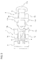
- FIG. 2 One example of a mounting layout of such plural cameras is shown in FIG. 2 .
- a left front-section camera 11a and a right front-section camera 11b are mounted on both a left side position and right side position of the vehicle front section 1 at rear positions of the vehicle front section 1.
- a rear view camera 11c, a left rear-section camera 11d and a right rear-section camera 11e are mounted on the vehicle rear section 2.
- These cameras 11a-11e are all mounted on the corresponding bodies, and their fields of vision are directed obliquely downward.
- Camera pictures captured by the cameras 11a-11e are transformed to bird' s eye view images ranging over angles of view of the cameras 11a-11e.
- each camera 11 when each camera 11 is arranged at a predetermined height position and captures with the optical axis CA of its object glass directed obliquely downward at an angle ⁇ , a camera image P is obtained. From the camera image P having this angle ⁇ , a coordinate-transformed image is formed such that as shown by an imaginary line in the figure, an optical axis VA extends from a virtual viewpoint VF at right angles relative to the camera image P. In this manner, each camera image captured from an obliquely upper viewpoint of an angle ⁇ can be transformed to a bird's eye view image.
- a camera image an image after image corrections such as distortion correction have been performed
- FIG. 4A When a camera image (an image after image corrections such as distortion correction have been performed) shown, for example, in FIG. 4A is subjected to coordinate transformation, a bird' s eye view image such as that shown in FIG. 4B is obtained.
- FIG. 5 One example of a display on the monitor 12 is shown in FIG. 5 .
- a character image 1C of the front section as obtained by characterizing a body image of the vehicle front section 1
- a character image 2C of the rear section as obtained by characterizing a body image of the vehicle rear section 1.
- a vehicle image VC is formed by these character images.
- Designated at signs 11A-11E are the individual bird's eye view images obtained by subjecting the camera images, which have been acquired by the respective cameras 11a-11e, to the coordinate transformation.
- the individual bird's eye view images are displayed, as a composite bird's eye view image composed from them, together with the vehicle image on the monitor 12.
- letter L designates a caution range guideline set around the vehicle image VC, and this caution range guideline L indicates a boundary of a zone set to be dangerous if a personnel or material obstacle such as a human or structural object is located inside.
- the vehicle front section 12 and the vehicle rear section 2 are connected to each other via the pivot pin 10 in the articulated wheel loader (see FIG. 1 ), and as shown in FIG. 6 , the vehicle front section 1 and the vehicle rear section 2 are bendable relative to each other from side to side about the pivot pin 10.
- the articulated wheel loader takes a bent posture during traveling of the vehicle or working, the display of the vehicle image on the monitor 12 is correspondingly brought to the bent state shown in FIG. 7 .
- the vehicle rear section 2 is displayed on the monitor 12 as the fixed-side character image 2C fixed at a predetermined position
- the vehicle front section 1 is displayed on the monitor 12 as the movable-side character image 1C bendable relative to the fixed-side character image 2C.
- the individual bird's eye view images 11A-11E are fixedly displayed, and the individual bird' s eye view images 11A,11B based on the cameras 11a,11b mounted on the vehicle front section 1 are displayed such that they are movable corresponding to the angle of articulation.
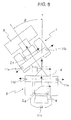
- a coordinate system is set as ⁇ around the pivot axis 10 between the vehicle rear section 2 and the vehicle front section 1, and coordinate systems for the vehicle front section 1 and vehicle rear section 2 are also set as ⁇ f, ⁇ g, all on the screen of the monitor, as shown in FIG. 8 .
- the coordinate axis ⁇ g of the vehicle rear section 2 is fixed because the vehicle rear section 2 is displayed as the fixed-side character image 2C.
- the coordinate system ⁇ and coordinate system ⁇ f rotate over the steering angle ⁇ .
- the vehicle image VC shown in the bent state in FIG. 7 is formed based on the dimensions and steering angle ⁇ upon displaying the vehicle front section 1 and vehicle rear section 2, and is displayed together with the composite bird's eye view image on the monitor 12.
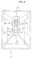
- the cameras 11a-11e are set in position and angle of view such that the individual bird' s eye view images 11A-11E are made sure to partly overlap.
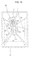
- these cameras are set similarly in position and angle of view irrespective of whether the articulated wheel loader is in the non-bent state shown in FIG. 9 or in a maximally bent state when the articulated wheel loader has been brought into the bent state shown in FIG. 10 .
- actual view field ranges of respective individual bird's eye view images 11A-11E are indicated by FA-FE.
- image signals are processed as will be descried hereafter. At overlapping portions of each two adjacent ones of the individual bird's eye view images, one of the images is used in preference to the other and the other image is processed to bring it to a partly non-displayed state.
- the vehicle rear section 2 is displayed as the fixed-side character image 2C while the vehicle front section 1 is displayed as the movable-side character image 1C.
- the display area on the monitor 12 is, therefore, set such that the respective display areas of the individual bird's eye view images 11C-11E on the side of the fixed-side character image 2C are fixed and the respective display areas of the individual bird's eye view images 11A, 11B on the side of the movable-side character image 1C are changeable.
- the composite bird's eye view image changes from the state shown in FIG. 5 such that as shown in FIG.
- the display area of the individual bird' s eye view image 11A on the left side decreases while the display area of the individual bird's eye view image 11B on the right side increases.
- a monitoring image is displayed all around the articulated wheel loader except for a forward field of vision, where visual recognition is feasible for an operator, irrespective of whether or not the articulated wheel loader is bent.
- a controller 20 of the circuit configuration depicted in FIG. 11 is arranged.
- Camera image signals acquired by the cameras 11a-11e are inputted to the controller 20, where these camera image signals are subjected to image corrections such as distortion correction as needed by an image correction means 21.
- An image transformation means 22 is connected to the image correction means 21, and by this image transformation means 22, the individual camera image signals are coordinate-transformed to bird' s eye view image signals such that the respective optical axes extend at right angles.
- the individual bird's eye view images 11A-11E are formed as described above, and signal processing is performed by an image composing means 23 such that these individual bird's eye view images 11A-11E are displayed at their corresponding display areas.
- the display areas for the individual bird's eye view images 11A-11E are allotted based on the positions of the individual cameras 11a-11e and the posture state of the articulated wheel loader.
- the controller 20 is provided with a camera position identifyingmeans 24.
- Information on the steering angle ⁇ is inputted to the controller 20 via a transmission means 25 for information on the body of the articulated wheel loader (hereinafter called “the vehicle information transmission means 25"), and is then inputted to the camera position identifying means 24.
- the controller is also configured to obtain, from a camera position storage means 26, information on the positions of the individual cameras 11a-11e at the time of the non-bent state.
- the display areas to be allotted to the individual bird's eye view images 11A-11E are determined based on the origin points of the individual cameras 11a-11e and the angle of articulation between the vehicle front section 1 and the vehicle rear section 2, whereby the composite bird's eye view image is formed.
- the angle of bending between the vehicle front section 1 and the vehicle rear section 2 as obtained based on the information concerning the steering angle from the vehicle information transmission means 25 is inputted in a vehicle image creation means 27 upon displaying the vehicle image VC on the monitor 12, whereby the vehicle image VC is formed.
- the above-mentioned composite bird' s eye view image and vehicle image VC are then inputted to a display image creation means 28, and based on image signals transmitted from the display image creation means 28, a monitoring image of the surroundings is displayed on the monitor 12.
- the operator when the operator performs machine operations in the operator's cab on the vehicle rear section 2 of the articulated wheel loader, the operator can confirm, by watching the monitor 12 especially during traveling, whether or not there is any personnel or material obstacle such as a human or structural object in the surroundings. Owing to the display of the composite bird' s eye view image around the vehicle image VC and the additional display of the caution range guideline L over the composite bird's eye view image, the operator can accurately grasp the direction and distance to such a personnel or material obstacle by watching the monitor 12, thereby making it possible to achieve assurance of work safety, an improvement in work efficiency, and the like.
- the vehicle front section 1 and the vehicle rear section 2 are bendably connected to each other, it is necessary to have this bent state reflected to the display on the monitor 12.
- the operator is located in the operator's cab 8 on the vehicle rear section 2, and the working mechanism is arranged on the vehicle front section 1. Therefore, the vehicle front section 1 and the loader bucket 3, which makes up the working mechanism, are visible from the inside of the operator's cab 8. Without watching the monitor 12 in particular, forward movements of the vehicle and work to be performed by driving the working mechanism can hence be performed safely and efficiently.
- FIG. 12 a front view and a plan view of an articulated dump truck as another example of the articulated working machine are shown in FIG. 12 and FIG. 13 , respectively.
- FIG. 14 is a plan view of the articulated dump truck in a bent state.
- a vehicle front section 30 includes an operator's cab 31, and a vessel 33 is arranged in a vehicle rear section 32.
- the vessel 33 is able to tilt rear-ward by hydraulic cylinders 34.
- the vehicle front section 30 is provided with a pair of wheels 35, while the vehicle rear section 32 is provided with two pairs of wheels 36.
- the vehicle front section 30 and a frame 37, which makes up the vehicle rear section 32, are connected to each other via a pivot pin 38, so that the articulated dump truck is displaceable to the non-bent state shown in FIG. 13 and also to the bent state shown in FIG. 14 .
- Cameras 39a,39b are mounted on left and right side portions of the front vehicle section 30 at positions near a connecting part to the vehicle rear section 32 via the pivot pin 38. With respect to the vehicle rear section 32, cameras 39c,39d,39e are also mounted at a position on a rear part of the frame 37 and at left and right side positions between the front and rear wheels 36, 36, respectively. As in the above-described first embodiment, camera images captured by these individual cameras 39a-39e are subjected to coordinate transformation such that upper viewpoint images are formed, whereby individual bird' s eye view images 39A-39E are obtained.
- a composite bird's eye view image formed by composed of individual bird's eye view images 39A-39E is displayed together with a vehicle image of the articulated dump truck on a monitor 40 as shown in FIG. 15 . It is to be noted that the articulated dump truck is shown in a bent state in FIG. 15 .
- the vehicle front section 30 and vehicle rear section 32 are displayed as the fixed-side character image and movable-side character image, respectively, when the operator' s cab 31 is used as a basis. It is, however, possible to configure such that the vehicle rear section 32 is displayed as the fixed-side character image on the monitor 40 at the time of reverse movement, because the vehicle rear section 32 is longer than the vehicle front section 30, and moreover, no rear field of vision can be practically obtained from the operator's cab 31.
- the vehicle rear section 32 is shown as a fixed-side character image 32c
- the vehicle front section 30 is shown as a movable-side character image 30C.
- the vehicle information transmission means 25 is connected to the vehicle image creation means 27 and camera position identifying means 24, and from this vehicle information transmission means 25, not only information on a steering angle but also various other information can be acquired. It is, accordingly, possible to obtain, from the vehicle information transmission means 25, information as to whether the vehicle is moving forward or reverse and then to change the display mode of the monitor 40 based on a signal representing this information.
Applications Claiming Priority (2)
| Application Number | Priority Date | Filing Date | Title |
|---|---|---|---|
| JP2011107815 | 2011-05-13 | ||
| PCT/JP2012/060104 WO2012157379A1 (ja) | 2011-05-13 | 2012-04-13 | 作業機械の周囲監視装置 |
Publications (2)
| Publication Number | Publication Date |
|---|---|
| EP2712969A1 true EP2712969A1 (de) | 2014-04-02 |
| EP2712969A4 EP2712969A4 (de) | 2015-04-29 |
Family
ID=47176719
Family Applications (1)
| Application Number | Title | Priority Date | Filing Date |
|---|---|---|---|
| EP20120785367 Withdrawn EP2712969A4 (de) | 2011-05-13 | 2012-04-13 | Vorrichtung zur überwachung des bereichs rund um eine arbeitsmaschine |
Country Status (7)
| Country | Link |
|---|---|
| US (1) | US20140088824A1 (de) |
| EP (1) | EP2712969A4 (de) |
| JP (1) | JP5779244B2 (de) |
| KR (1) | KR20140043374A (de) |
| CN (1) | CN103547747A (de) |
| AU (1) | AU2012257053A1 (de) |
| WO (1) | WO2012157379A1 (de) |
Cited By (8)
| Publication number | Priority date | Publication date | Assignee | Title |
|---|---|---|---|---|
| EP3064646A1 (de) * | 2015-03-04 | 2016-09-07 | Dynapac GmbH | Strassenbaumaschine und verfahren zum betreiben einer selbstfahrenden strassenbaumschine |
| EP3110142A4 (de) * | 2014-02-17 | 2017-11-29 | Hitachi Construction Machinery Co., Ltd. | Überwachung einer bildanzeigevorrichtung einer industriemaschine |
| CN107431789A (zh) * | 2017-02-09 | 2017-12-01 | 株式会社小松制作所 | 作业车辆的周边监视系统、作业车辆以及作业车辆的周边监视方法 |
| WO2018095489A1 (de) * | 2016-11-25 | 2018-05-31 | Conti Temic Microelectronic Gmbh | Bildverarbeitungssystem und bildverarbeitungsverfahren |
| EP3783156A4 (de) * | 2018-09-14 | 2022-01-26 | Komatsu Ltd. | Anzeigesystem für radlader und steuerverfahren für ein anzeigesystem |
| CN114763701A (zh) * | 2021-01-14 | 2022-07-19 | 现代斗山英维高株式会社 | 工程机械的控制系统及方法 |
| EP4105392A4 (de) * | 2020-03-31 | 2023-07-19 | Kobelco Construction Machinery Co., Ltd. | Peripheriedetektionsvorrichtung für eine arbeitsmaschine |
| EP4254317A1 (de) * | 2022-03-28 | 2023-10-04 | Canon Kabushiki Kaisha | Bildverarbeitungsvorrichtung, bildverarbeitungsverfahren und speichermedium |
Families Citing this family (83)
| Publication number | Priority date | Publication date | Assignee | Title |
|---|---|---|---|---|
| GB2447672B (en) | 2007-03-21 | 2011-12-14 | Ford Global Tech Llc | Vehicle manoeuvring aids |
| WO2011158955A1 (ja) * | 2010-06-18 | 2011-12-22 | 日立建機株式会社 | 作業機械の周囲監視装置 |
| US9500497B2 (en) | 2011-04-19 | 2016-11-22 | Ford Global Technologies, Llc | System and method of inputting an intended backing path |
| US9513103B2 (en) | 2011-04-19 | 2016-12-06 | Ford Global Technologies, Llc | Hitch angle sensor assembly |
| US9374562B2 (en) | 2011-04-19 | 2016-06-21 | Ford Global Technologies, Llc | System and method for calculating a horizontal camera to target distance |
| US9555832B2 (en) | 2011-04-19 | 2017-01-31 | Ford Global Technologies, Llc | Display system utilizing vehicle and trailer dynamics |
| US9854209B2 (en) * | 2011-04-19 | 2017-12-26 | Ford Global Technologies, Llc | Display system utilizing vehicle and trailer dynamics |
| US9434414B2 (en) | 2011-04-19 | 2016-09-06 | Ford Global Technologies, Llc | System and method for determining a hitch angle offset |
| US9969428B2 (en) | 2011-04-19 | 2018-05-15 | Ford Global Technologies, Llc | Trailer backup assist system with waypoint selection |
| US9506774B2 (en) | 2011-04-19 | 2016-11-29 | Ford Global Technologies, Llc | Method of inputting a path for a vehicle and trailer |
| US10196088B2 (en) | 2011-04-19 | 2019-02-05 | Ford Global Technologies, Llc | Target monitoring system and method |
| US9723274B2 (en) | 2011-04-19 | 2017-08-01 | Ford Global Technologies, Llc | System and method for adjusting an image capture setting |
| US9926008B2 (en) | 2011-04-19 | 2018-03-27 | Ford Global Technologies, Llc | Trailer backup assist system with waypoint selection |
| US9683848B2 (en) | 2011-04-19 | 2017-06-20 | Ford Global Technologies, Llc | System for determining hitch angle |
| US9373044B2 (en) | 2011-07-25 | 2016-06-21 | Ford Global Technologies, Llc | Trailer lane departure warning system |
| US8768583B2 (en) * | 2012-03-29 | 2014-07-01 | Harnischfeger Technologies, Inc. | Collision detection and mitigation systems and methods for a shovel |
| US9592851B2 (en) | 2013-02-04 | 2017-03-14 | Ford Global Technologies, Llc | Control modes for a trailer backup assist system |
| US9511799B2 (en) | 2013-02-04 | 2016-12-06 | Ford Global Technologies, Llc | Object avoidance for a trailer backup assist system |
| US9517668B2 (en) | 2014-07-28 | 2016-12-13 | Ford Global Technologies, Llc | Hitch angle warning system and method |
| US9963004B2 (en) | 2014-07-28 | 2018-05-08 | Ford Global Technologies, Llc | Trailer sway warning system and method |
| US9437055B2 (en) * | 2014-08-13 | 2016-09-06 | Bendix Commercial Vehicle Systems Llc | Cabin and trailer body movement determination with camera at the back of the cabin |
| US9714037B2 (en) | 2014-08-18 | 2017-07-25 | Trimble Navigation Limited | Detection of driver behaviors using in-vehicle systems and methods |
| WO2016028816A1 (en) | 2014-08-18 | 2016-02-25 | Trimble Navigation Limited | System and method for modifying onboard event detection and/or image capture strategy using external source data |
| US10161746B2 (en) | 2014-08-18 | 2018-12-25 | Trimble Navigation Limited | Systems and methods for cargo management |
| EP3020868B1 (de) * | 2014-11-14 | 2020-11-04 | Caterpillar Inc. | Maschine mit einem Maschinenkörper und einem hinsichtlich des Körpers beweglichen Werkzeug mit einem System zur Unterstützung eines Benutzers der Maschine |
| US9533683B2 (en) | 2014-12-05 | 2017-01-03 | Ford Global Technologies, Llc | Sensor failure mitigation system and mode management |
| US9522677B2 (en) | 2014-12-05 | 2016-12-20 | Ford Global Technologies, Llc | Mitigation of input device failure and mode management |
| US9607242B2 (en) | 2015-01-16 | 2017-03-28 | Ford Global Technologies, Llc | Target monitoring system with lens cleaning device |
| US9667875B2 (en) | 2015-01-21 | 2017-05-30 | Caterpillar Inc. | Vision system and method of monitoring surroundings of machine |
| US9522699B2 (en) | 2015-02-05 | 2016-12-20 | Ford Global Technologies, Llc | Trailer backup assist system with adaptive steering angle limits |
| US9616923B2 (en) | 2015-03-03 | 2017-04-11 | Ford Global Technologies, Llc | Topographical integration for trailer backup assist system |
| US9804022B2 (en) | 2015-03-24 | 2017-10-31 | Ford Global Technologies, Llc | System and method for hitch angle detection |
| JPWO2016174754A1 (ja) | 2015-04-28 | 2018-02-15 | 株式会社小松製作所 | 作業機械の周辺監視装置及び作業機械の周辺監視方法 |
| US10204159B2 (en) | 2015-08-21 | 2019-02-12 | Trimble Navigation Limited | On-demand system and method for retrieving video from a commercial vehicle |
| EP3344519B1 (de) * | 2015-09-02 | 2020-06-24 | Volvo Truck Corporation | Vorrichtung und ein verfahren zum wenden einer gelenkfahrzeugkombination |
| US9896130B2 (en) | 2015-09-11 | 2018-02-20 | Ford Global Technologies, Llc | Guidance system for a vehicle reversing a trailer along an intended backing path |
| US10611407B2 (en) | 2015-10-19 | 2020-04-07 | Ford Global Technologies, Llc | Speed control for motor vehicles |
| US10384607B2 (en) | 2015-10-19 | 2019-08-20 | Ford Global Technologies, Llc | Trailer backup assist system with hitch angle offset estimation |
| JP2017081238A (ja) * | 2015-10-23 | 2017-05-18 | 株式会社小松製作所 | 表示システムおよび作業車両 |
| US9836060B2 (en) | 2015-10-28 | 2017-12-05 | Ford Global Technologies, Llc | Trailer backup assist system with target management |
| US10017115B2 (en) | 2015-11-11 | 2018-07-10 | Ford Global Technologies, Llc | Trailer monitoring system and method |
| US9610975B1 (en) | 2015-12-17 | 2017-04-04 | Ford Global Technologies, Llc | Hitch angle detection for trailer backup assist system |
| US9827818B2 (en) | 2015-12-17 | 2017-11-28 | Ford Global Technologies, Llc | Multi-stage solution for trailer hitch angle initialization |
| US10155478B2 (en) | 2015-12-17 | 2018-12-18 | Ford Global Technologies, Llc | Centerline method for trailer hitch angle detection |
| US9798953B2 (en) | 2015-12-17 | 2017-10-24 | Ford Global Technologies, Llc | Template matching solution for locating trailer hitch point |
| US9796228B2 (en) | 2015-12-17 | 2017-10-24 | Ford Global Technologies, Llc | Hitch angle detection for trailer backup assist system |
| US10011228B2 (en) | 2015-12-17 | 2018-07-03 | Ford Global Technologies, Llc | Hitch angle detection for trailer backup assist system using multiple imaging devices |
| US9934572B2 (en) | 2015-12-17 | 2018-04-03 | Ford Global Technologies, Llc | Drawbar scan solution for locating trailer hitch point |
| JP6737288B2 (ja) | 2016-01-13 | 2020-08-05 | 株式会社ソシオネクスト | 周囲監視装置、画像処理方法、及び画像処理プログラム |
| US10005492B2 (en) | 2016-02-18 | 2018-06-26 | Ford Global Technologies, Llc | Trailer length and hitch angle bias estimation |
| WO2016137017A1 (ja) * | 2016-03-28 | 2016-09-01 | 株式会社小松製作所 | 評価装置及び評価方法 |
| WO2017077723A1 (ja) | 2016-03-29 | 2017-05-11 | 株式会社小松製作所 | 作業車両 |
| US10112646B2 (en) | 2016-05-05 | 2018-10-30 | Ford Global Technologies, Llc | Turn recovery human machine interface for trailer backup assist |
| US10106193B2 (en) | 2016-07-01 | 2018-10-23 | Ford Global Technologies, Llc | Enhanced yaw rate trailer angle detection initialization |
| US10046800B2 (en) | 2016-08-10 | 2018-08-14 | Ford Global Technologies, Llc | Trailer wheel targetless trailer angle detection |
| JP6886258B2 (ja) * | 2016-08-31 | 2021-06-16 | 株式会社小松製作所 | ホイールローダおよびホイールローダの制御方法 |
| JP2018050119A (ja) * | 2016-09-20 | 2018-03-29 | 国立大学法人 東京大学 | 作業車両の表示システム |
| US10222804B2 (en) | 2016-10-21 | 2019-03-05 | Ford Global Technologies, Llc | Inertial reference for TBA speed limiting |
| US10594934B2 (en) | 2016-11-17 | 2020-03-17 | Bendix Commercial Vehicle Systems Llc | Vehicle display |
| EP3553234A4 (de) * | 2016-12-06 | 2020-03-18 | Sumitomo (S.H.I.) Construction Machinery Co., Ltd. | Baumaschinen |
| JP6662762B2 (ja) * | 2016-12-19 | 2020-03-11 | 株式会社クボタ | 作業車 |
| US20180201132A1 (en) * | 2017-01-13 | 2018-07-19 | Deere & Company | Mobile machine-user protocol system and method |
| EP3385458B1 (de) * | 2017-02-09 | 2023-03-29 | Komatsu Ltd. | Arbeitsfahrzeug und anzeigevorrichtung |
| JP6819462B2 (ja) * | 2017-05-30 | 2021-01-27 | コベルコ建機株式会社 | 作業機械 |
| JP6822427B2 (ja) * | 2017-06-09 | 2021-01-27 | 株式会社デンソー | 地図変化点検出装置 |
| US10710585B2 (en) | 2017-09-01 | 2020-07-14 | Ford Global Technologies, Llc | Trailer backup assist system with predictive hitch angle functionality |
| JP7103796B2 (ja) * | 2018-01-31 | 2022-07-20 | 株式会社小松製作所 | 作業機械 |
| US10883256B2 (en) * | 2018-05-25 | 2021-01-05 | Deere & Company | Object responsive control system for a work machine |
| JP7220027B2 (ja) * | 2018-06-14 | 2023-02-09 | フォルシアクラリオン・エレクトロニクス株式会社 | 運転支援装置 |
| US11077795B2 (en) | 2018-11-26 | 2021-08-03 | Ford Global Technologies, Llc | Trailer angle detection using end-to-end learning |
| US11592813B2 (en) * | 2018-12-17 | 2023-02-28 | Robert Bosch Gmbh | Method and controller for the situational transmission of surroundings information of a vehicle |
| JP7160701B2 (ja) * | 2019-01-23 | 2022-10-25 | 株式会社小松製作所 | 作業機械のシステム及び方法 |
| US10829046B2 (en) | 2019-03-06 | 2020-11-10 | Ford Global Technologies, Llc | Trailer angle detection using end-to-end learning |
| JP7280089B2 (ja) * | 2019-03-29 | 2023-05-23 | 日立建機株式会社 | ホイールローダ |
| JP2020173524A (ja) * | 2019-04-09 | 2020-10-22 | 清水建設株式会社 | 監視システム |
| US10949685B2 (en) | 2019-07-22 | 2021-03-16 | Caterpillar Inc. | Excluding a component of a work machine from a video frame based on motion information |
| JP7055158B2 (ja) * | 2020-02-13 | 2022-04-15 | 株式会社クボタ | 作業車 |
| JP7437195B2 (ja) | 2020-03-13 | 2024-02-22 | 株式会社小松製作所 | モータグレーダおよび表示制御方法 |
| KR102362953B1 (ko) * | 2020-06-04 | 2022-02-16 | (주)에이치브레인 | Fpga 기반 뉴로머신과 svm을 이용한 굴삭기 안전시스템 |
| US11575810B2 (en) * | 2020-09-09 | 2023-02-07 | Deere & Company | Auto-positioning camera for drawn implements |
| US11653587B2 (en) * | 2020-09-17 | 2023-05-23 | Deere & Company | System and method for presenting the surroundings of an agricultural implement |
| JP2023102618A (ja) * | 2022-01-12 | 2023-07-25 | 株式会社小松製作所 | 作業機械、作業機械を制御するための方法、及びシステム |
| KR20240056273A (ko) * | 2022-10-21 | 2024-04-30 | 에이치디현대인프라코어 주식회사 | 건설기계의 제어 시스템 및 방법 |
Family Cites Families (16)
| Publication number | Priority date | Publication date | Assignee | Title |
|---|---|---|---|---|
| DE10035223A1 (de) * | 2000-07-20 | 2002-01-31 | Daimler Chrysler Ag | Vorrichtung und Verfahren zur Überwachung der Umgebung eines Objekts |
| JP2003235036A (ja) * | 2002-02-07 | 2003-08-22 | Nissan Motor Co Ltd | 車両用画像表示装置 |
| JP4332027B2 (ja) * | 2003-12-25 | 2009-09-16 | キャタピラージャパン株式会社 | 表示器制御システム |
| JP2006256544A (ja) * | 2005-03-18 | 2006-09-28 | Aisin Seiki Co Ltd | 後退運転支援装置 |
| JP5054294B2 (ja) * | 2005-08-05 | 2012-10-24 | 株式会社小松製作所 | 作業用車両に搭載される表示装置、及び同表示装置の表示方法 |
| DE102006037600B4 (de) * | 2006-08-10 | 2010-03-04 | Daimler Ag | Verfahren zur auflösungsabhängigen Darstellung der Umgebung eines Kraftfahrzeugs |
| JP4996928B2 (ja) * | 2007-01-05 | 2012-08-08 | 日立建機株式会社 | 作業機械の周囲監視装置 |
| JP4847913B2 (ja) * | 2007-03-30 | 2011-12-28 | 日立建機株式会社 | 作業機械周辺監視装置 |
| JP2009060499A (ja) * | 2007-09-03 | 2009-03-19 | Sanyo Electric Co Ltd | 運転支援システム及び連結車両 |
| JP2009107602A (ja) * | 2007-11-01 | 2009-05-21 | Komatsu Ltd | アーティキュレート式建設機械 |
| KR101078341B1 (ko) * | 2009-02-12 | 2011-11-01 | 볼보 컨스트럭션 이큅먼트 에이비 | 후방 감시수단이 구비된 건설장비 |
| JP5124672B2 (ja) * | 2011-06-07 | 2013-01-23 | 株式会社小松製作所 | 作業車両の周辺監視装置 |
| AU2012268476B2 (en) * | 2011-06-07 | 2014-05-15 | Komatsu Ltd. | Perimeter monitoring device for work vehicle |
| JP5124671B2 (ja) * | 2011-06-07 | 2013-01-23 | 株式会社小松製作所 | 作業車両の周辺監視装置 |
| JP5781978B2 (ja) * | 2012-05-22 | 2015-09-24 | 株式会社小松製作所 | ダンプトラック |
| US9446713B2 (en) * | 2012-09-26 | 2016-09-20 | Magna Electronics Inc. | Trailer angle detection system |
-
2012
- 2012-04-13 US US14/116,884 patent/US20140088824A1/en not_active Abandoned
- 2012-04-13 EP EP20120785367 patent/EP2712969A4/de not_active Withdrawn
- 2012-04-13 AU AU2012257053A patent/AU2012257053A1/en not_active Abandoned
- 2012-04-13 WO PCT/JP2012/060104 patent/WO2012157379A1/ja active Application Filing
- 2012-04-13 CN CN201280022215.2A patent/CN103547747A/zh active Pending
- 2012-04-13 KR KR1020137032343A patent/KR20140043374A/ko not_active Application Discontinuation
- 2012-04-13 JP JP2013515049A patent/JP5779244B2/ja not_active Expired - Fee Related
Cited By (13)
| Publication number | Priority date | Publication date | Assignee | Title |
|---|---|---|---|---|
| EP3110142A4 (de) * | 2014-02-17 | 2017-11-29 | Hitachi Construction Machinery Co., Ltd. | Überwachung einer bildanzeigevorrichtung einer industriemaschine |
| US10650251B2 (en) | 2014-02-17 | 2020-05-12 | Hitachi Construction Machinery Co., Ltd. | Monitoring image display device of industrial machine |
| EP3064646A1 (de) * | 2015-03-04 | 2016-09-07 | Dynapac GmbH | Strassenbaumaschine und verfahren zum betreiben einer selbstfahrenden strassenbaumschine |
| WO2018095489A1 (de) * | 2016-11-25 | 2018-05-31 | Conti Temic Microelectronic Gmbh | Bildverarbeitungssystem und bildverarbeitungsverfahren |
| US10421400B2 (en) | 2017-02-09 | 2019-09-24 | Komatsu Ltd. | Surroundings monitoring system for work vehicle, work vehicle, and surroundings monitoring method for work vehicle |
| CN107431789B (zh) * | 2017-02-09 | 2018-12-21 | 株式会社小松制作所 | 作业车辆的周边监视系统、作业车辆以及作业车辆的周边监视方法 |
| EP3226553A4 (de) * | 2017-02-09 | 2018-01-10 | Komatsu Ltd. | Umgebungsüberwachungssystem für arbeitsfahrzeug, arbeitsfahrzeug und umgebungsüberwachungsverfahren für ein arbeitsfahrzeug |
| CN107431789A (zh) * | 2017-02-09 | 2017-12-01 | 株式会社小松制作所 | 作业车辆的周边监视系统、作业车辆以及作业车辆的周边监视方法 |
| EP3783156A4 (de) * | 2018-09-14 | 2022-01-26 | Komatsu Ltd. | Anzeigesystem für radlader und steuerverfahren für ein anzeigesystem |
| EP4105392A4 (de) * | 2020-03-31 | 2023-07-19 | Kobelco Construction Machinery Co., Ltd. | Peripheriedetektionsvorrichtung für eine arbeitsmaschine |
| CN114763701A (zh) * | 2021-01-14 | 2022-07-19 | 现代斗山英维高株式会社 | 工程机械的控制系统及方法 |
| EP4029998A1 (de) * | 2021-01-14 | 2022-07-20 | Hyundai Doosan Infracore Co., Ltd. | System und verfahren zur steuerung einer baumaschine |
| EP4254317A1 (de) * | 2022-03-28 | 2023-10-04 | Canon Kabushiki Kaisha | Bildverarbeitungsvorrichtung, bildverarbeitungsverfahren und speichermedium |
Also Published As
| Publication number | Publication date |
|---|---|
| KR20140043374A (ko) | 2014-04-09 |
| WO2012157379A1 (ja) | 2012-11-22 |
| JP5779244B2 (ja) | 2015-09-16 |
| EP2712969A4 (de) | 2015-04-29 |
| CN103547747A (zh) | 2014-01-29 |
| JPWO2012157379A1 (ja) | 2014-07-31 |
| US20140088824A1 (en) | 2014-03-27 |
| AU2012257053A1 (en) | 2013-11-21 |
Similar Documents
| Publication | Publication Date | Title |
|---|---|---|
| EP2712969A1 (de) | Vorrichtung zur überwachung des bereichs rund um eine arbeitsmaschine | |
| EP2717570A1 (de) | Vorrichtung zur überwachung des bereichs rund um eine arbeitsmaschine | |
| JP5269026B2 (ja) | 作業機械の周囲監視装置 | |
| US20170341581A1 (en) | Display device for self-propelled industrial machine | |
| JP5546427B2 (ja) | 作業機械の周囲監視装置 | |
| CN113152552B (zh) | 工程机械的控制系统及方法 | |
| EP2757782A1 (de) | Umgebungsüberwachungsvorrichtung für eine arbeitsmaschine | |
| JP5775283B2 (ja) | 作業機械のモニタ装置 | |
| WO2018043091A1 (ja) | ホイールローダおよびホイールローダの制御方法 | |
| CN112112202B (zh) | 操纵辅助系统、操纵辅助方法以及建筑机械 | |
| WO2016140016A1 (ja) | 車両の周囲監視装置 | |
| EP3751845B1 (de) | Steuerungsvorrichtung für arbeitsmaschinen | |
| EP3739131B1 (de) | Baumaschine | |
| US20210246635A1 (en) | Display system for work machine | |
| CN114868382A (zh) | 作业辅助服务器、拍摄装置的选择方法 | |
| WO2022195988A1 (ja) | 遠隔操作支援サーバおよび遠隔操作支援システム | |
| CN113359691B (zh) | 一种非道路移动设备的远程图像显示装置和方法 | |
| US20230304265A1 (en) | Work machine and display system | |
| US20240141621A1 (en) | Display control device, display control method, and work machine | |
| KR20240056262A (ko) | 건설기계의 제어 시스템 및 방법 | |
| KR20240056273A (ko) | 건설기계의 제어 시스템 및 방법 | |
| CN115088251A (zh) | 远程操作装置、远程操作辅助服务器、远程操作辅助系统以及远程操作辅助方法 |
Legal Events
| Date | Code | Title | Description |
|---|---|---|---|
| PUAI | Public reference made under article 153(3) epc to a published international application that has entered the european phase |
Free format text: ORIGINAL CODE: 0009012 |
|
| 17P | Request for examination filed |
Effective date: 20131213 |
|
| AK | Designated contracting states |
Kind code of ref document: A1 Designated state(s): AL AT BE BG CH CY CZ DE DK EE ES FI FR GB GR HR HU IE IS IT LI LT LU LV MC MK MT NL NO PL PT RO RS SE SI SK SM TR |
|
| DAX | Request for extension of the european patent (deleted) | ||
| RA4 | Supplementary search report drawn up and despatched (corrected) |
Effective date: 20150401 |
|
| RIC1 | Information provided on ipc code assigned before grant |
Ipc: E02F 9/26 20060101AFI20150326BHEP Ipc: H04N 7/18 20060101ALI20150326BHEP Ipc: G06F 11/32 20060101ALI20150326BHEP Ipc: E02F 9/08 20060101ALI20150326BHEP Ipc: G06K 9/00 20060101ALI20150326BHEP Ipc: B60R 11/04 20060101ALI20150326BHEP Ipc: E02F 9/24 20060101ALI20150326BHEP |
|
| STAA | Information on the status of an ep patent application or granted ep patent |
Free format text: STATUS: THE APPLICATION HAS BEEN WITHDRAWN |
|
| 18W | Application withdrawn |
Effective date: 20160125 |