EP2712939B1 - Multimedia-Quenchsystem und Verfahren - Google Patents
Multimedia-Quenchsystem und Verfahren Download PDFInfo
- Publication number
- EP2712939B1 EP2712939B1 EP13004630.3A EP13004630A EP2712939B1 EP 2712939 B1 EP2712939 B1 EP 2712939B1 EP 13004630 A EP13004630 A EP 13004630A EP 2712939 B1 EP2712939 B1 EP 2712939B1
- Authority
- EP
- European Patent Office
- Prior art keywords
- quenching
- chamber
- metal
- workload
- vegetable oil
- Prior art date
- Legal status (The legal status is an assumption and is not a legal conclusion. Google has not performed a legal analysis and makes no representation as to the accuracy of the status listed.)
- Active
Links
Images



Classifications
-
- C—CHEMISTRY; METALLURGY
- C21—METALLURGY OF IRON
- C21D—MODIFYING THE PHYSICAL STRUCTURE OF FERROUS METALS; GENERAL DEVICES FOR HEAT TREATMENT OF FERROUS OR NON-FERROUS METALS OR ALLOYS; MAKING METAL MALLEABLE, e.g. BY DECARBURISATION OR TEMPERING
- C21D1/00—General methods or devices for heat treatment, e.g. annealing, hardening, quenching or tempering
- C21D1/18—Hardening; Quenching with or without subsequent tempering
-
- C—CHEMISTRY; METALLURGY
- C21—METALLURGY OF IRON
- C21D—MODIFYING THE PHYSICAL STRUCTURE OF FERROUS METALS; GENERAL DEVICES FOR HEAT TREATMENT OF FERROUS OR NON-FERROUS METALS OR ALLOYS; MAKING METAL MALLEABLE, e.g. BY DECARBURISATION OR TEMPERING
- C21D1/00—General methods or devices for heat treatment, e.g. annealing, hardening, quenching or tempering
- C21D1/56—General methods or devices for heat treatment, e.g. annealing, hardening, quenching or tempering characterised by the quenching agents
- C21D1/58—Oils
-
- C—CHEMISTRY; METALLURGY
- C21—METALLURGY OF IRON
- C21D—MODIFYING THE PHYSICAL STRUCTURE OF FERROUS METALS; GENERAL DEVICES FOR HEAT TREATMENT OF FERROUS OR NON-FERROUS METALS OR ALLOYS; MAKING METAL MALLEABLE, e.g. BY DECARBURISATION OR TEMPERING
- C21D1/00—General methods or devices for heat treatment, e.g. annealing, hardening, quenching or tempering
- C21D1/62—Quenching devices
-
- C—CHEMISTRY; METALLURGY
- C21—METALLURGY OF IRON
- C21D—MODIFYING THE PHYSICAL STRUCTURE OF FERROUS METALS; GENERAL DEVICES FOR HEAT TREATMENT OF FERROUS OR NON-FERROUS METALS OR ALLOYS; MAKING METAL MALLEABLE, e.g. BY DECARBURISATION OR TEMPERING
- C21D1/00—General methods or devices for heat treatment, e.g. annealing, hardening, quenching or tempering
- C21D1/62—Quenching devices
- C21D1/63—Quenching devices for bath quenching
-
- C—CHEMISTRY; METALLURGY
- C21—METALLURGY OF IRON
- C21D—MODIFYING THE PHYSICAL STRUCTURE OF FERROUS METALS; GENERAL DEVICES FOR HEAT TREATMENT OF FERROUS OR NON-FERROUS METALS OR ALLOYS; MAKING METAL MALLEABLE, e.g. BY DECARBURISATION OR TEMPERING
- C21D1/00—General methods or devices for heat treatment, e.g. annealing, hardening, quenching or tempering
- C21D1/62—Quenching devices
- C21D1/63—Quenching devices for bath quenching
- C21D1/64—Quenching devices for bath quenching with circulating liquids
-
- C—CHEMISTRY; METALLURGY
- C21—METALLURGY OF IRON
- C21D—MODIFYING THE PHYSICAL STRUCTURE OF FERROUS METALS; GENERAL DEVICES FOR HEAT TREATMENT OF FERROUS OR NON-FERROUS METALS OR ALLOYS; MAKING METAL MALLEABLE, e.g. BY DECARBURISATION OR TEMPERING
- C21D1/00—General methods or devices for heat treatment, e.g. annealing, hardening, quenching or tempering
- C21D1/68—Temporary coatings or embedding materials applied before or during heat treatment
- C21D1/70—Temporary coatings or embedding materials applied before or during heat treatment while heating or quenching
-
- C—CHEMISTRY; METALLURGY
- C21—METALLURGY OF IRON
- C21D—MODIFYING THE PHYSICAL STRUCTURE OF FERROUS METALS; GENERAL DEVICES FOR HEAT TREATMENT OF FERROUS OR NON-FERROUS METALS OR ALLOYS; MAKING METAL MALLEABLE, e.g. BY DECARBURISATION OR TEMPERING
- C21D11/00—Process control or regulation for heat treatments
- C21D11/005—Process control or regulation for heat treatments for cooling
Definitions
- the invention relates to a quenching process for heat treated metal parts, and in particular to a system and process for quenching and cleaning such metal parts with biodegradable media.
- the key to successfully accomplishing this process is the uniform removal of heat from the surface of the metal part.
- Continuous cooling curves showing the cooling rates for a ferrous alloy are shown in Figure 1 .
- the first curve (1) is designed to provide a combination of martensite and austenite in the as-quenched metal.
- the second curve (2) is designed to provide a fully martensitic structure in the as-quenched metal.
- the third curve (3) is designed to provide a combination of martensite and bainite and the fourth curve (4) is designed to provide a combination of martensite and pearlite in the as-quenched metal.
- quenchants are water, quenching oils, aqueous polymer solutions, molten salts, and high pressure inert gas.
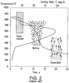
- Quenching in a liquid typically includes three stages which are illustrated in Figure 2 . These stages of liquid quenching may not occur at all points on a part at the same time.
- vapor blanket or film boiling occurs where a thin film of vaporized liquid forms in close proximity to the surface of the metal and prevents the liquid from coming into contact with the surface to thereby cool the metal surface.
- This stage is characterized by a low convective heat transfer.
- nucleate boiling occurs wherein the liquid vaporizes at the surface of the metal part with a very high heat exchange.
- the boiling point of the quenchant determines the end of this stage.
- molten salt quench does not have a vapor stage or a boiling stage. Therefore, like a gas quench, molten salt quenching provides a purely convective heat transfer with the highest heat transfer right at the start of the immersion of the components into the molten salt.
- the salts have to be molten in order to be used, their application temperature is by nature higher than those of water and oil. They are normally used in the range about 140°C to about 350°C. This higher application temperature has the positive effect of reducing the quenching severity in the lower temperature range where martensitic transformation takes place. This is also beneficial for uniform stress distribution which results in very low distortion of the hardened metal components.
- Forced gas quenching is a single-stage quenching of a purely convective type.
- Gas type, gas pressure, and gas velocity are the main control parameters.
- a gas quenching chamber is equipped with a powerful fan and is adapted for injecting a cooling gas at a positive pressure of up to 20 bar.
- the gas quenching chamber may include one or more heat-exchangers using chilled water to quickly remove heat from the quenching gas.
- the most common quenching gas medium is nitrogen gas. However, other gases are also used such as argon gas, helium gas, hydrogen gas, and mixtures thereof.
- Quenching with high pressure gas is preferable for high hardenability alloys.
- Typical grades of steels for which forced gas quenching is suitable include AISI-SAE grades 8620, 5120, and 4118, 17CrNiMo6, SAE grades 9310, 3310, 8822H, 4822, and 8630.
- lower hardenability, plain carbon steels that can be carburized and oil quenched simply cannot be hardened using a gas quench because they will not properly transform under the slower cooling rates of gas quenching.
- Even with high hardenability grades some consideration must be given to core hardness, because the gas quench will produce lower core hardness compared to oil quenched parts.
- HPGQ High Pressure Gas Quench
- HPGQ can sometimes eliminate post-heat treatment straightening or clamp tempering operations, reduce grind stock allowances and hard machining, or replace more costly processes such as press quenching
- gas quenching When properly applied, gas quenching has several recognized advantages, which include safety, overall economics, reduction of secondary manufacturing operations, minimizing of dimensional variation, controllable cooling rates, part cleanliness, and overall environmental impact.
- the peak of the oil cooling rate in the boiling phase is 80°C/s and takes place in the important phase of steel quenching to avoid ferrite or pearlite formation.
- pearlite transformation For gas quenching, the limited quenching speed at high temperature (pearlite transformation) and high rate at low temperature (martensite transformation).
- WO 2009/047211 A1 discloses a heat treatment plant for workpieces that has a rotary hearth furnace (1), a quenching facility (6), and a transport arrangement (10).
- WO 2004/099450 A1 discloses the use of a vegetable oil composition for quenching heat treated metals.
- US 201,2/0247627 A1 discloses a method and apparatus for rapid cooling of heat treated metal parts.
- EP 2 607 503 B1 discloses a quenching apparatus for cooling a heat treated workload.
- a process for cooling a metal workload that has been heated to an elevated temperature includes the steps of providing a metal workload that has been heated to an elevated temperature selected to cause the metal in the workload to transform to austenite and placing the metal workload in a quenching chamber while the metal workload is at the elevated temperature.
- the process also includes the steps of closing the quenching chamber and then quenching the metal workload.
- the quenching step is carried out by performing the following steps: flowing a vegetable oil quenchant over the metal workload and applying a positive pressure of an inert gas in the quenching chamber during said flowing step.
- the vegetable oil flow rate and the positive pressure of the inert gas are selected to provide a cooling rate that is sufficient to transform the metal to a second metallurgical phase within a preselected time period.
- the second metallurgical phase is one or more of martensite, bainite, and pearlite.
- the quenching process of this invention is designed for use on a steel work piece or a batch of such work pieces, (hereinafter, the workload) that has been heated to an elevated temperature at which the steel material transforms to a desired phase, typically austenite.
- the workload is preferably heated to a temperature of about 1400°F-2400°F for this purpose.
- the workload is preferably heated for a time duration selected to provide substantially full transformation to the austenitic phase. The time at temperature depends on the alloy composition and the cross-sectional dimensions of the workload.
- the heating step is conducted with the steel workload in a heating chamber that is connected to a quenching chamber. When the steel workload has been heated for the requisite period of time, the workload is transferred from the heating chamber to the quenching chamber.
- a quenchant comprising a vegetable oil
- a preferred vegetable oil quenchant is soybean oil.
- other vegetable-type oils such as cottonseed oil, canola oil, palm oil, sunflower seed oil, corn oil, and mixtures thereof with or without soybean oil may also be used.
- the vegetable oil quenchant is heated in a separate reservoir that is connected to the quenching chamber.
- the vegetable oil quenchant is preferably heated to a temperature of about 70°F-1000°F depending on the nature of the alloy to be quenched.
- the pressure inside the oil reservoir is raised to a desired level, preferably about 1 to 15 bar, by pumping in an inert gas such as nitrogen gas or argon gas.
- the quenching chamber When the workload has been transferred to the quenching chamber, the quenching chamber is closed and sealed. The vegetable oil quenchant is then allowed to flow from the reservoir into the quenching chamber. Preferably, this occurs by creating a pressure differential between the vegetable oil reservoir and the quenching chamber.
- the quenching chamber is adapted with piping and nozzles above and adjacent to the workload so that the vegetable oil quenchant floods or sprays over the workload and collects in the bottom of the quenching chamber. As the vegetable oil quenchant collects in the bottom of the quenching chamber, it is recirculated by a pump that draws the vegetable oil quenchant from the bottom of the quenching chamber and forces it through the piping and nozzles.
- an inert gas such as nitrogen gas is applied to the quenching chamber.
- the inert gas blanket also helps to inhibit oxidation of the vegetable oil quenchant.
- the inert gas is used at a pressure of up to 15 bar in the quenching chamber.
- the inert gas pressure may be constant through the quenching step.
- the gas pressure is varied during the quenching cycle to provide different cooling rates at different stages in the quenching cycle. Variation of the inert gas pressure provides control of the cooling rate during the quenching step. A lower pressure will reduce the boiling point and thus, the cooling rate. A higher pressure will increase the cooling rate.
- a two-step process can be used wherein the inert gas pressure is increased during the initial cooling of the workload and then the gas pressure is reduced when a desired transformation temperature is reached.
- Such a two-step process simulates the behavior of ideal quenching medium by providing faster cooling at the beginning of the quenching step and slower cooling at a later stage.
- the vegetable oil quenchant would provide high initial quenching speed in the critical hardening range when the pressure of the inert gas is increased and a slower final quenching speed through the low temperature range would be realized by reducing the pressure of the inert gas.
- the quenching process can be adapted to simulate such quenching techniques as martempering, hot oil quenching, and austempering.
- martempering hot oil quench, or austempering
- the inert gas pressure would be increased in the higher temperature range at the beginning of the quenching cycle.
- the inert gas pressure would be lowered during the lower temperature portion of the quenching cycle.
- the invention also includes a combination of vacuum and pressure during the quenching step to vary the cooling rate.
- the quenching step can be carried out with the quenching chamber initially under a positive pressure of inert gas, for example, up to about 10 bar to provide a faster cooling rate.
- the vegetable oil quenchant is removed from the quenching chamber.
- the vegetable oil quenchant is pumped back into the reservoir.
- some residual oil will remain on the as-quenched workload and this residual oil must be removed before the workload can be transferred for further processing. Therefore, the process according to this invention includes a cleaning step after the quenching step.
- a cleaning agent is introduced into the quenching chamber.
- the quenching chamber is preferably pumped down to a vacuum below about 5 torr.
- a solvent-type cleaning agent is injected into the quenching chamber as a mixture of liquid and vapor.
- the cleaning solvent is biodegradable type solvent such as soy methyl ester.
- soy methyl ester and ethyl lactate is expected to provide good cleaning results because it does not leave a film on the surface of the metal parts. The solvent liquid and vapor adheres to the surface of the parts to be cleaned.
- the parts are sprayed or soaked with clean liquid solvent from the solvent supply tank.
- a separate set of spray nozzles is arranged inside the quenching chamber so that the liquid solvent can be applied to multiple sides of the work load.
- a vapor recovery process is preferably carried out.
- the quenching chamber is pumped down again to promote evaporation of the liquid solvent.
- the solvent vapor is evacuated from the quenching chamber by the vacuum pump to a heat exchanger, where it is condensed back to liquid form, From the condenser the liquid solvent is returned to the solvent supply tank.
- the quenching chamber is restored to atmospheric pressure by backfilling the quenching chamber with inert gas.
- the remaining solvent, which would be vaporized is evacuated with a vacuum pump.
- the intake line of the vacuum pump is adapted with an activated carbon filter which adsorbs the solvent vapor to separate it from the inert gas.
- the oil and cleaning agent are preferably separated before they are returned to their respective reservoirs.
- Any known apparatus or system for oil separation can be used in connection with the quenching process and apparatus of the present invention.
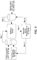
- the quenching apparatus 10 includes a quenching chamber 12.
- the quenching chamber 12 preferably includes a pressure vessel having one or more openings through which a workload can be transferred either into or out of the quenching chamber.
- a preferred embodiment of a quenching chamber is shown and described in copending application No. 13/723,368, filed December 21, 2012 .
- a reservoir or tank 14 for holding a volume of vegetable oil quenchant is operatively connected to the quenching chamber 12.
- the quenching chamber has piping and nozzles that are constructed and arranged inside the quenching chamber to spray or flood the vegetable oil quenchant over a workload in the quenching chamber 12.
- a pump (not shown) is preferably provided for pumping the oil quenchant that collects in the bottom of the quenching chamber through the nozzles so that the vegetable oil quenchant can be recirculated during the quenching cycle.
- a source 16 of inert gas, preferably nitrogen gas, is connected to the reservoir 14 and to the quenching chamber 12 to provide a pressurizing gas when desired.
- a vacuum pump 18 is connected to the quenching chamber 12 and the vegetable oil reservoir 14.
- the piping or other connections arranged between vacuum pump 18, the quenching chamber 12, and the vegetable oil reservoir 14 are adapted with suitable valving so that a vacuum can be drawn on the quenching chamber 12, the vegetable oil reservoir 14, or both,
- a cleaning agent reservoir 20 has an outlet that is operatively connected to the quenching chamber 12 to provide a cleaning fluid to be applied to a workload when the quenching step has been completed.
- the quenching chamber is adapted with piping and spray nozzles for applying the cleaning fluid to the workload.
- the quenching apparatus preferably includes an oil/cleaner separator 22,
- the oil/cleaner separator 22 has an inlet that is connected to a corresponding outlet in the quenching chamber 12 so that the mixture of oil and cleaner that collects in the quenching chamber after a quenching cycle can be transferred to the oil/cleaner separator 22.
- the oil/cleaner separator 22 includes a skimmer that is constructed and arranged to skim the used oil from the oil/cleaner mixture so that the oil and the cleaning agent can be reused.
- the oil/cleaner separator 22 may be realized by a SUPARATOR® brand oil separation system sold by Aqueous Recovery Resources, Inc. of Bedford Hill, New York.
- the oil/cleaner separator 22 has a first outlet that is connected to an inlet of the oil reservoir 1 4 and a second outlet that is connected to an inlet of the cleaning agent reservoir 20.
- the quenching apparatus 10 optionally includes a blower 24 having an exhaust outlet that is coupled to the quenching chamber 12 so that a cooling gas can be blown into the quenching chamber 12 to provide forced gas cooling of the workload instead of vegetable oil quenching.
- An outlet from the quenching chamber 12 is connected to an inlet of the blower 24 to provide a closed loop for the cooling gas.
- a heat exchanger 26 is connected between the quenching chamber outlet and the blower inlet for extracting heat from the cooling gas.
- the quenching process according to the present invention uses a vegetable oil as the primary quenching medium.
- the use of such oils is advantageous because of their biodegradability (up to 100%) and their increased flashpoint and boiling point.
- the vegetable oil quenchants do not show a vapor phase and therefore, provide increased cooling at the initial higher temperature of the quenching step.
- the vegetable oil quenching provides a lower cooling rate at the later lower temperature of the quenching step when the main heat transfer mode is convection. The lower cooling rate provides more uniform cooling through the part which results in producing less part distortion.
- the vegetable oil quenchant used in the process according to the present invention can be subject to oxidative instability if the oil is in contact with air. This oxidation will modify the oil quenching performance and lead to a dark surface on the as-quenched metal part.
- the performance of the quenching process under a blanket of inert gas substantially completely overcomes that disadvantage.
- the application of inert gas pressure at different stages of the quenching step can speed up or slow down the cooling rate so that the actual cooling characteristic can be tailored for the type of metal and the desired microstructure in the as-quenched condition.
Landscapes
- Chemical & Material Sciences (AREA)
- Engineering & Computer Science (AREA)
- Physics & Mathematics (AREA)
- Thermal Sciences (AREA)
- Crystallography & Structural Chemistry (AREA)
- Mechanical Engineering (AREA)
- Materials Engineering (AREA)
- Metallurgy (AREA)
- Organic Chemistry (AREA)
- Oil, Petroleum & Natural Gas (AREA)
- Heat Treatments In General, Especially Conveying And Cooling (AREA)
Claims (7)
- Verfahren zum Abkühlen einer Metallarbeitslast, die auf eine erhöhte Temperatur erhitzt wurde, umfassend die Schritte von:Bereitstellen einer Metallarbeitslast, die auf eine erhöhte Temperatur erhitzt wurde, die ausgewählt wurde, um zu bewirken, dass sich das Metall in der genannten Arbeitslast in Austenit umwandelt;Platzieren der Metallarbeitslast in einer Quenchkammer, während sich das Metallteil auf der erhöhten Temperatur befindet;Schließen der Quenchkammer; und dannQuenchen der Metallarbeitslast durch Ausführen der folgenden Schritte:Fließenlassen eines Pflanzenölquenchmittels über die Metallarbeitslast undAufbringen eines Überdrucks eines Inertgases in der Quenchkammer während des genannten Fließschritts;wobei der Durchfluss des Pflanzenöls und der Überdruck des Inertgases ausgewählt sind, um eine Abkühlungsgeschwindigkeit bereitzustellen, die ausreicht, um das Metall innerhalb eines vorgewählten Zeitraums in eine zweite metallurgische Phase umzuwandeln, undwobei die zweite metallurgische Phase eine oder mehrere aus Martensit, Bainit und Perlit ist.
- Verfahren nach Anspruch 1, wobei der Schritt des Aufbringens des Überdrucks von Inertgas in der Quenchkammer die Schritte umfasst von:Erhöhen des Drucks des Inertgases während einer Anfangsphase des Fließschritts, um eine erste Abkühlungsgeschwindigkeit bereitzustellen, und dannVerringern des Drucks des Inertgases während einer zweiten Stufe des Fließschritts, um eine zweite Abkühlungsgeschwindigkeit bereitzustellen, die langsamer als die erste Abkühlungsgeschwindigkeit ist.
- Verfahren nach Anspruch 1, umfassend den Schritt des Erhitzens des Pflanzenölquenchmittels auf eine Temperatur von 20 °C bis 200 °C, bevor der genannte Fließschritt ausgeführt wird.
- Verfahren nach Anspruch 3, wobei der Erhitzungsschritt in einer zweiten verschließbaren Kammer durchgeführt wird und das Verfahren den Schritt des Druckbeaufschlagens der zweiten verschließbaren Kammer mit dem Inertgas umfasst.
- Verfahren nach Anspruch 1, wobei das Verfahren ferner den Schritt des Entfernens des Pflanzenölquenchmittels von dem Metallteil nach dem Quenchschritt umfasst.
- Verfahren nach Anspruch 5, wobei der Schritt des Entfernens des Pflanzenölquenchmittels von dem Metallteil die Schritte umfasst von:Ablassen des Pflanzenölquenchmittels aus der Kammer;Evakuieren der Kammer, um einen Unterdruck in der Kammer bereitzustellen;Einspritzen eines Reinigungsfluids in die Kammer, sodass das Reinigungsfluid an den Oberflächen des Metallteils haftet; und dannAufbringen einer Reinigungsflüssigkeit auf die Oberfläche des Metallteils, um die Oberfläche des Metallteils zu spülen.
- Verfahren nach Anspruch 6, umfassend die Schritte von
erneutem Evakuieren der Kammer nach dem genannten Reinigungsflüssigkeitsaufbringungsschritt, wobei die Reinigungsflüssigkeit verdampft, um einen Dampf zu bilden; und dann
Ziehen des Dampfes aus der Kammer.
Priority Applications (1)
| Application Number | Priority Date | Filing Date | Title |
|---|---|---|---|
| PL13004630T PL2712939T3 (pl) | 2012-09-28 | 2013-09-24 | System i proces hartowania w wielu ośrodkach |
Applications Claiming Priority (1)
| Application Number | Priority Date | Filing Date | Title |
|---|---|---|---|
| US201261707596P | 2012-09-28 | 2012-09-28 |
Publications (2)
| Publication Number | Publication Date |
|---|---|
| EP2712939A1 EP2712939A1 (de) | 2014-04-02 |
| EP2712939B1 true EP2712939B1 (de) | 2021-08-25 |
Family
ID=49301248
Family Applications (1)
| Application Number | Title | Priority Date | Filing Date |
|---|---|---|---|
| EP13004630.3A Active EP2712939B1 (de) | 2012-09-28 | 2013-09-24 | Multimedia-Quenchsystem und Verfahren |
Country Status (4)
| Country | Link |
|---|---|
| US (1) | US9458519B2 (de) |
| EP (1) | EP2712939B1 (de) |
| JP (1) | JP6302199B2 (de) |
| PL (1) | PL2712939T3 (de) |
Families Citing this family (4)
| Publication number | Priority date | Publication date | Assignee | Title |
|---|---|---|---|---|
| CN105154639A (zh) * | 2015-07-28 | 2015-12-16 | 大连海威石油化工有限公司 | 一种生物热处理油及其制备方法 |
| US20170074589A1 (en) | 2015-09-11 | 2017-03-16 | Ipsen Inc. | System and Method for Facilitating the Maintenance of an Industrial Furnace |
| CN113667805A (zh) * | 2021-07-29 | 2021-11-19 | 宁波晟光金属制品有限公司 | 一种热油热能回收系统 |
| CN113512633B (zh) * | 2021-08-04 | 2022-09-06 | 长春电子科技学院 | 一种热处理的智能水循环装置 |
Citations (2)
| Publication number | Priority date | Publication date | Assignee | Title |
|---|---|---|---|---|
| EP2505676A1 (de) * | 2011-03-28 | 2012-10-03 | Ipsen, Inc. | Abschreckungsverfahren und Vorrichtung zur Ausführung des Verfahrens |
| EP2607503A1 (de) * | 2011-12-22 | 2013-06-26 | Ipsen, Inc. | Löschkammer mit integrierter Zugangstür |
Family Cites Families (21)
| Publication number | Priority date | Publication date | Assignee | Title |
|---|---|---|---|---|
| FR2379607A1 (fr) | 1977-02-03 | 1978-09-01 | Vide & Traitement Sa | Procede pour le traitement thermique de metaux |
| JPS5811726A (ja) | 1981-07-13 | 1983-01-22 | Nittoku Kako Center:Kk | 光輝焼入法 |
| JPS6071077A (ja) * | 1983-09-29 | 1985-04-22 | 椛澤 均 | 洗浄方法および洗浄装置 |
| JPS6443386A (en) * | 1987-08-06 | 1989-02-15 | Nissei Eng Kk | Vacuum washing method and device |
| JPH04180517A (ja) | 1990-11-14 | 1992-06-26 | Nissan Motor Co Ltd | 鋼部材の加工方法 |
| JP3030735B2 (ja) | 1991-12-25 | 2000-04-10 | 光洋サーモシステム株式会社 | 脱脂洗浄方法および装置 |
| DE59309658D1 (de) | 1993-04-21 | 1999-07-22 | Ipsen Ind Int Gmbh | Flexible adaptive Abschreckung |
| US5616549A (en) * | 1995-12-29 | 1997-04-01 | Clark; Lawrence A. | Molecular level cleaning of contaminates from parts utilizing an envronmentally safe solvent |
| JP3895000B2 (ja) | 1996-06-06 | 2007-03-22 | Dowaホールディングス株式会社 | 浸炭焼入焼戻方法及び装置 |
| JPH11153386A (ja) * | 1997-11-25 | 1999-06-08 | Ishikawajima Harima Heavy Ind Co Ltd | 多室式マルチ冷却真空炉 |
| US6120613A (en) | 1998-04-30 | 2000-09-19 | Micell Technologies, Inc. | Carbon dioxide cleaning and separation systems |
| JP2000167498A (ja) * | 1998-12-01 | 2000-06-20 | Honda Motor Co Ltd | 真空洗浄機 |
| JP4837160B2 (ja) | 2000-03-02 | 2011-12-14 | 出光興産株式会社 | 熱処理方法 |
| US6312509B1 (en) | 2000-08-10 | 2001-11-06 | Ebrahim Moradian | Rust preventive coating composition |
| JP2003183728A (ja) * | 2001-12-14 | 2003-07-03 | Jh Corp | 真空熱処理装置 |
| JP4698921B2 (ja) * | 2002-01-22 | 2011-06-08 | 出光興産株式会社 | 焼入れ方法 |
| EP1625240B1 (de) | 2003-05-09 | 2006-12-20 | A. & A. Fratelli Parodi S.R.L. | Abschreckflüssigkeitzusammensetzung |
| DE112005000546B4 (de) * | 2004-03-10 | 2015-01-29 | Idemitsu Kosan Co., Ltd. | Abschrecköl zum Abschrecken unter vermindertem Druck und Verfahren zum Abschrecken |
| DE102005015450B3 (de) * | 2005-04-04 | 2006-08-17 | Ipsen International Gmbh | Verfahren sowie Vorrichtung zur Gasabschreckung |
| DE102007048041A1 (de) | 2007-10-05 | 2009-04-09 | Loi Thermprocess Gmbh | Drehherdofen |
| JP5906005B2 (ja) * | 2010-03-25 | 2016-04-20 | 株式会社Ihi | 熱処理方法 |
-
2013
- 2013-09-11 US US14/023,810 patent/US9458519B2/en active Active
- 2013-09-24 EP EP13004630.3A patent/EP2712939B1/de active Active
- 2013-09-24 PL PL13004630T patent/PL2712939T3/pl unknown
- 2013-09-27 JP JP2013201063A patent/JP6302199B2/ja active Active
Patent Citations (2)
| Publication number | Priority date | Publication date | Assignee | Title |
|---|---|---|---|---|
| EP2505676A1 (de) * | 2011-03-28 | 2012-10-03 | Ipsen, Inc. | Abschreckungsverfahren und Vorrichtung zur Ausführung des Verfahrens |
| EP2607503A1 (de) * | 2011-12-22 | 2013-06-26 | Ipsen, Inc. | Löschkammer mit integrierter Zugangstür |
Also Published As
| Publication number | Publication date |
|---|---|
| JP6302199B2 (ja) | 2018-03-28 |
| PL2712939T3 (pl) | 2022-01-24 |
| US20140090754A1 (en) | 2014-04-03 |
| US9458519B2 (en) | 2016-10-04 |
| EP2712939A1 (de) | 2014-04-02 |
| JP2014111826A (ja) | 2014-06-19 |
Similar Documents
| Publication | Publication Date | Title |
|---|---|---|
| US9458519B2 (en) | Process for cooling a metal workload in a multimedia quench system | |
| CN101368275A (zh) | 42CrMoE热处理工艺 | |
| CN102534465B (zh) | 一种液压件表面硬化碳氮共渗热处理工艺 | |
| CN108118283A (zh) | 一种可提高硬度梯度的表面强化热处理方法 | |
| US20120211126A1 (en) | Method of induction heating and quenching | |
| CN103589839B (zh) | 一种高碳高铬不锈钢的热处理工艺 | |
| WO2025156621A1 (zh) | 提高高强度低合金钢工件韧性的多级多相热处理方法 | |
| CN111500833A (zh) | 一种阀门耐热钢铸件热处理工艺 | |
| CN114959206A (zh) | 一种轴承钢真空气淬工艺 | |
| JP6533146B2 (ja) | 焼入れ方法および焼入れ装置 | |
| US6174389B1 (en) | Fixture and method for selectively quenching a predetermined area of a workpiece | |
| CN114045377A (zh) | 一种中碳钢表面激光相变强化方法 | |
| JP2017186584A (ja) | 熱処理方法、及び、軸受軌道輪の製造方法 | |
| CN113846284B (zh) | 一种25Cr2Ni3Mo材料离子氮化工艺 | |
| US20120325372A1 (en) | Method for reduction of time in a gas carburizing process and cooling apparatus utilizing a high speed quenching oil flow rate | |
| CN1176227C (zh) | 一种提高合金结构钢硬度的热处理方法 | |
| JP2002097520A5 (de) | ||
| JP2005213646A5 (de) | ||
| JP2001089809A (ja) | 高周波焼入れ方法及びその装置 | |
| Chaudhari et al. | Effect of quenching parameters on material characteristics of specimen: An overview | |
| CN112708734A (zh) | 一种具有提高耐磨性的热处理工艺 | |
| CN121718690A (zh) | 铸球淬火方法及淬火剂 | |
| JP6328937B2 (ja) | サブゼロ処理方法及び装置 | |
| JP2005133212A (ja) | 熱処理システム | |
| RU2830082C2 (ru) | Способ обработки карданных колец игольчатых подшипников из стали |
Legal Events
| Date | Code | Title | Description |
|---|---|---|---|
| PUAI | Public reference made under article 153(3) epc to a published international application that has entered the european phase |
Free format text: ORIGINAL CODE: 0009012 |
|
| AK | Designated contracting states |
Kind code of ref document: A1 Designated state(s): AL AT BE BG CH CY CZ DE DK EE ES FI FR GB GR HR HU IE IS IT LI LT LU LV MC MK MT NL NO PL PT RO RS SE SI SK SM TR |
|
| AX | Request for extension of the european patent |
Extension state: BA ME |
|
| STAA | Information on the status of an ep patent application or granted ep patent |
Free format text: STATUS: EXAMINATION IS IN PROGRESS |
|
| 17Q | First examination report despatched |
Effective date: 20161116 |
|
| GRAP | Despatch of communication of intention to grant a patent |
Free format text: ORIGINAL CODE: EPIDOSNIGR1 |
|
| STAA | Information on the status of an ep patent application or granted ep patent |
Free format text: STATUS: GRANT OF PATENT IS INTENDED |
|
| RIC1 | Information provided on ipc code assigned before grant |
Ipc: C21D 1/64 20060101ALI20200603BHEP Ipc: F27D 3/00 20060101ALI20200603BHEP Ipc: C21D 1/58 20060101ALI20200603BHEP Ipc: C21D 11/00 20060101AFI20200603BHEP Ipc: C21D 1/18 20060101ALI20200603BHEP Ipc: F27D 15/02 20060101ALI20200603BHEP Ipc: C21D 1/62 20060101ALI20200603BHEP Ipc: C21D 1/63 20060101ALI20200603BHEP Ipc: C21D 1/70 20060101ALI20200603BHEP |
|
| INTG | Intention to grant announced |
Effective date: 20200706 |
|
| GRAJ | Information related to disapproval of communication of intention to grant by the applicant or resumption of examination proceedings by the epo deleted |
Free format text: ORIGINAL CODE: EPIDOSDIGR1 |
|
| STAA | Information on the status of an ep patent application or granted ep patent |
Free format text: STATUS: EXAMINATION IS IN PROGRESS |
|
| GRAP | Despatch of communication of intention to grant a patent |
Free format text: ORIGINAL CODE: EPIDOSNIGR1 |
|
| STAA | Information on the status of an ep patent application or granted ep patent |
Free format text: STATUS: GRANT OF PATENT IS INTENDED |
|
| INTC | Intention to grant announced (deleted) | ||
| INTG | Intention to grant announced |
Effective date: 20201207 |
|
| GRAJ | Information related to disapproval of communication of intention to grant by the applicant or resumption of examination proceedings by the epo deleted |
Free format text: ORIGINAL CODE: EPIDOSDIGR1 |
|
| STAA | Information on the status of an ep patent application or granted ep patent |
Free format text: STATUS: EXAMINATION IS IN PROGRESS |
|
| GRAJ | Information related to disapproval of communication of intention to grant by the applicant or resumption of examination proceedings by the epo deleted |
Free format text: ORIGINAL CODE: EPIDOSDIGR1 |
|
| STAA | Information on the status of an ep patent application or granted ep patent |
Free format text: STATUS: GRANT OF PATENT IS INTENDED |
|
| GRAJ | Information related to disapproval of communication of intention to grant by the applicant or resumption of examination proceedings by the epo deleted |
Free format text: ORIGINAL CODE: EPIDOSDIGR1 |
|
| GRAP | Despatch of communication of intention to grant a patent |
Free format text: ORIGINAL CODE: EPIDOSNIGR1 |
|
| STAA | Information on the status of an ep patent application or granted ep patent |
Free format text: STATUS: EXAMINATION IS IN PROGRESS |
|
| GRAP | Despatch of communication of intention to grant a patent |
Free format text: ORIGINAL CODE: EPIDOSNIGR1 |
|
| STAA | Information on the status of an ep patent application or granted ep patent |
Free format text: STATUS: GRANT OF PATENT IS INTENDED |
|
| GRAJ | Information related to disapproval of communication of intention to grant by the applicant or resumption of examination proceedings by the epo deleted |
Free format text: ORIGINAL CODE: EPIDOSDIGR1 |
|
| INTC | Intention to grant announced (deleted) | ||
| STAA | Information on the status of an ep patent application or granted ep patent |
Free format text: STATUS: EXAMINATION IS IN PROGRESS |
|
| GRAP | Despatch of communication of intention to grant a patent |
Free format text: ORIGINAL CODE: EPIDOSNIGR1 |
|
| STAA | Information on the status of an ep patent application or granted ep patent |
Free format text: STATUS: GRANT OF PATENT IS INTENDED |
|
| INTG | Intention to grant announced |
Effective date: 20210503 |
|
| INTC | Intention to grant announced (deleted) | ||
| INTG | Intention to grant announced |
Effective date: 20210520 |
|
| GRAS | Grant fee paid |
Free format text: ORIGINAL CODE: EPIDOSNIGR3 |
|
| GRAA | (expected) grant |
Free format text: ORIGINAL CODE: 0009210 |
|
| STAA | Information on the status of an ep patent application or granted ep patent |
Free format text: STATUS: THE PATENT HAS BEEN GRANTED |
|
| AK | Designated contracting states |
Kind code of ref document: B1 Designated state(s): AL AT BE BG CH CY CZ DE DK EE ES FI FR GB GR HR HU IE IS IT LI LT LU LV MC MK MT NL NO PL PT RO RS SE SI SK SM TR |
|
| REG | Reference to a national code |
Ref country code: GB Ref legal event code: FG4D |
|
| REG | Reference to a national code |
Ref country code: CH Ref legal event code: EP |
|
| REG | Reference to a national code |
Ref country code: IE Ref legal event code: FG4D Ref country code: AT Ref legal event code: REF Ref document number: 1423858 Country of ref document: AT Kind code of ref document: T Effective date: 20210915 |
|
| REG | Reference to a national code |
Ref country code: DE Ref legal event code: R096 Ref document number: 602013078917 Country of ref document: DE |
|
| REG | Reference to a national code |
Ref country code: LT Ref legal event code: MG9D |
|
| REG | Reference to a national code |
Ref country code: NL Ref legal event code: MP Effective date: 20210825 |
|
| REG | Reference to a national code |
Ref country code: AT Ref legal event code: MK05 Ref document number: 1423858 Country of ref document: AT Kind code of ref document: T Effective date: 20210825 |
|
| PG25 | Lapsed in a contracting state [announced via postgrant information from national office to epo] |
Ref country code: HR Free format text: LAPSE BECAUSE OF FAILURE TO SUBMIT A TRANSLATION OF THE DESCRIPTION OR TO PAY THE FEE WITHIN THE PRESCRIBED TIME-LIMIT Effective date: 20210825 Ref country code: SE Free format text: LAPSE BECAUSE OF FAILURE TO SUBMIT A TRANSLATION OF THE DESCRIPTION OR TO PAY THE FEE WITHIN THE PRESCRIBED TIME-LIMIT Effective date: 20210825 Ref country code: NO Free format text: LAPSE BECAUSE OF FAILURE TO SUBMIT A TRANSLATION OF THE DESCRIPTION OR TO PAY THE FEE WITHIN THE PRESCRIBED TIME-LIMIT Effective date: 20211125 Ref country code: PT Free format text: LAPSE BECAUSE OF FAILURE TO SUBMIT A TRANSLATION OF THE DESCRIPTION OR TO PAY THE FEE WITHIN THE PRESCRIBED TIME-LIMIT Effective date: 20211227 Ref country code: RS Free format text: LAPSE BECAUSE OF FAILURE TO SUBMIT A TRANSLATION OF THE DESCRIPTION OR TO PAY THE FEE WITHIN THE PRESCRIBED TIME-LIMIT Effective date: 20210825 Ref country code: ES Free format text: LAPSE BECAUSE OF FAILURE TO SUBMIT A TRANSLATION OF THE DESCRIPTION OR TO PAY THE FEE WITHIN THE PRESCRIBED TIME-LIMIT Effective date: 20210825 Ref country code: FI Free format text: LAPSE BECAUSE OF FAILURE TO SUBMIT A TRANSLATION OF THE DESCRIPTION OR TO PAY THE FEE WITHIN THE PRESCRIBED TIME-LIMIT Effective date: 20210825 Ref country code: LT Free format text: LAPSE BECAUSE OF FAILURE TO SUBMIT A TRANSLATION OF THE DESCRIPTION OR TO PAY THE FEE WITHIN THE PRESCRIBED TIME-LIMIT Effective date: 20210825 Ref country code: AT Free format text: LAPSE BECAUSE OF FAILURE TO SUBMIT A TRANSLATION OF THE DESCRIPTION OR TO PAY THE FEE WITHIN THE PRESCRIBED TIME-LIMIT Effective date: 20210825 Ref country code: BG Free format text: LAPSE BECAUSE OF FAILURE TO SUBMIT A TRANSLATION OF THE DESCRIPTION OR TO PAY THE FEE WITHIN THE PRESCRIBED TIME-LIMIT Effective date: 20211125 |
|
| PG25 | Lapsed in a contracting state [announced via postgrant information from national office to epo] |
Ref country code: LV Free format text: LAPSE BECAUSE OF FAILURE TO SUBMIT A TRANSLATION OF THE DESCRIPTION OR TO PAY THE FEE WITHIN THE PRESCRIBED TIME-LIMIT Effective date: 20210825 Ref country code: GR Free format text: LAPSE BECAUSE OF FAILURE TO SUBMIT A TRANSLATION OF THE DESCRIPTION OR TO PAY THE FEE WITHIN THE PRESCRIBED TIME-LIMIT Effective date: 20211126 |
|
| PG25 | Lapsed in a contracting state [announced via postgrant information from national office to epo] |
Ref country code: NL Free format text: LAPSE BECAUSE OF FAILURE TO SUBMIT A TRANSLATION OF THE DESCRIPTION OR TO PAY THE FEE WITHIN THE PRESCRIBED TIME-LIMIT Effective date: 20210825 |
|
| PG25 | Lapsed in a contracting state [announced via postgrant information from national office to epo] |
Ref country code: DK Free format text: LAPSE BECAUSE OF FAILURE TO SUBMIT A TRANSLATION OF THE DESCRIPTION OR TO PAY THE FEE WITHIN THE PRESCRIBED TIME-LIMIT Effective date: 20210825 |
|
| REG | Reference to a national code |
Ref country code: CH Ref legal event code: PL |
|
| REG | Reference to a national code |
Ref country code: BE Ref legal event code: MM Effective date: 20210930 |
|
| REG | Reference to a national code |
Ref country code: DE Ref legal event code: R097 Ref document number: 602013078917 Country of ref document: DE |
|
| PG25 | Lapsed in a contracting state [announced via postgrant information from national office to epo] |
Ref country code: SM Free format text: LAPSE BECAUSE OF FAILURE TO SUBMIT A TRANSLATION OF THE DESCRIPTION OR TO PAY THE FEE WITHIN THE PRESCRIBED TIME-LIMIT Effective date: 20210825 Ref country code: SK Free format text: LAPSE BECAUSE OF FAILURE TO SUBMIT A TRANSLATION OF THE DESCRIPTION OR TO PAY THE FEE WITHIN THE PRESCRIBED TIME-LIMIT Effective date: 20210825 Ref country code: RO Free format text: LAPSE BECAUSE OF FAILURE TO SUBMIT A TRANSLATION OF THE DESCRIPTION OR TO PAY THE FEE WITHIN THE PRESCRIBED TIME-LIMIT Effective date: 20210825 Ref country code: MC Free format text: LAPSE BECAUSE OF FAILURE TO SUBMIT A TRANSLATION OF THE DESCRIPTION OR TO PAY THE FEE WITHIN THE PRESCRIBED TIME-LIMIT Effective date: 20210825 Ref country code: EE Free format text: LAPSE BECAUSE OF FAILURE TO SUBMIT A TRANSLATION OF THE DESCRIPTION OR TO PAY THE FEE WITHIN THE PRESCRIBED TIME-LIMIT Effective date: 20210825 Ref country code: CZ Free format text: LAPSE BECAUSE OF FAILURE TO SUBMIT A TRANSLATION OF THE DESCRIPTION OR TO PAY THE FEE WITHIN THE PRESCRIBED TIME-LIMIT Effective date: 20210825 Ref country code: AL Free format text: LAPSE BECAUSE OF FAILURE TO SUBMIT A TRANSLATION OF THE DESCRIPTION OR TO PAY THE FEE WITHIN THE PRESCRIBED TIME-LIMIT Effective date: 20210825 |
|
| PLBE | No opposition filed within time limit |
Free format text: ORIGINAL CODE: 0009261 |
|
| STAA | Information on the status of an ep patent application or granted ep patent |
Free format text: STATUS: NO OPPOSITION FILED WITHIN TIME LIMIT |
|
| PG25 | Lapsed in a contracting state [announced via postgrant information from national office to epo] |
Ref country code: LU Free format text: LAPSE BECAUSE OF NON-PAYMENT OF DUE FEES Effective date: 20210924 Ref country code: IE Free format text: LAPSE BECAUSE OF NON-PAYMENT OF DUE FEES Effective date: 20210924 Ref country code: BE Free format text: LAPSE BECAUSE OF NON-PAYMENT OF DUE FEES Effective date: 20210930 |
|
| 26N | No opposition filed |
Effective date: 20220527 |
|
| PG25 | Lapsed in a contracting state [announced via postgrant information from national office to epo] |
Ref country code: SI Free format text: LAPSE BECAUSE OF FAILURE TO SUBMIT A TRANSLATION OF THE DESCRIPTION OR TO PAY THE FEE WITHIN THE PRESCRIBED TIME-LIMIT Effective date: 20210825 Ref country code: LI Free format text: LAPSE BECAUSE OF NON-PAYMENT OF DUE FEES Effective date: 20210930 Ref country code: CH Free format text: LAPSE BECAUSE OF NON-PAYMENT OF DUE FEES Effective date: 20210930 |
|
| PG25 | Lapsed in a contracting state [announced via postgrant information from national office to epo] |
Ref country code: HU Free format text: LAPSE BECAUSE OF FAILURE TO SUBMIT A TRANSLATION OF THE DESCRIPTION OR TO PAY THE FEE WITHIN THE PRESCRIBED TIME-LIMIT; INVALID AB INITIO Effective date: 20130924 |
|
| PG25 | Lapsed in a contracting state [announced via postgrant information from national office to epo] |
Ref country code: CY Free format text: LAPSE BECAUSE OF FAILURE TO SUBMIT A TRANSLATION OF THE DESCRIPTION OR TO PAY THE FEE WITHIN THE PRESCRIBED TIME-LIMIT Effective date: 20210825 |
|
| P01 | Opt-out of the competence of the unified patent court (upc) registered |
Effective date: 20230603 |
|
| PG25 | Lapsed in a contracting state [announced via postgrant information from national office to epo] |
Ref country code: MK Free format text: LAPSE BECAUSE OF FAILURE TO SUBMIT A TRANSLATION OF THE DESCRIPTION OR TO PAY THE FEE WITHIN THE PRESCRIBED TIME-LIMIT Effective date: 20210825 |
|
| PG25 | Lapsed in a contracting state [announced via postgrant information from national office to epo] |
Ref country code: MT Free format text: LAPSE BECAUSE OF FAILURE TO SUBMIT A TRANSLATION OF THE DESCRIPTION OR TO PAY THE FEE WITHIN THE PRESCRIBED TIME-LIMIT Effective date: 20210825 |
|
| PGFP | Annual fee paid to national office [announced via postgrant information from national office to epo] |
Ref country code: DE Payment date: 20250919 Year of fee payment: 13 |
|
| PGFP | Annual fee paid to national office [announced via postgrant information from national office to epo] |
Ref country code: PL Payment date: 20250912 Year of fee payment: 13 Ref country code: IT Payment date: 20250923 Year of fee payment: 13 |
|
| PGFP | Annual fee paid to national office [announced via postgrant information from national office to epo] |
Ref country code: GB Payment date: 20250918 Year of fee payment: 13 |
|
| PGFP | Annual fee paid to national office [announced via postgrant information from national office to epo] |
Ref country code: FR Payment date: 20250922 Year of fee payment: 13 |
|
| PG25 | Lapsed in a contracting state [announced via postgrant information from national office to epo] |
Ref country code: TR Free format text: LAPSE BECAUSE OF FAILURE TO SUBMIT A TRANSLATION OF THE DESCRIPTION OR TO PAY THE FEE WITHIN THE PRESCRIBED TIME-LIMIT Effective date: 20210825 |