EP2711510B1 - Mécanisme d'actionnement variable de soupapes pour moteur à combustion interne - Google Patents
Mécanisme d'actionnement variable de soupapes pour moteur à combustion interne Download PDFInfo
- Publication number
- EP2711510B1 EP2711510B1 EP13182323.9A EP13182323A EP2711510B1 EP 2711510 B1 EP2711510 B1 EP 2711510B1 EP 13182323 A EP13182323 A EP 13182323A EP 2711510 B1 EP2711510 B1 EP 2711510B1
- Authority
- EP
- European Patent Office
- Prior art keywords
- arm
- main arm
- plate portions
- variable valve
- valve mechanism
- Prior art date
- Legal status (The legal status is an assumption and is not a legal conclusion. Google has not performed a legal analysis and makes no representation as to the accuracy of the status listed.)
- Not-in-force
Links
Images


Classifications
-
- F—MECHANICAL ENGINEERING; LIGHTING; HEATING; WEAPONS; BLASTING
- F01—MACHINES OR ENGINES IN GENERAL; ENGINE PLANTS IN GENERAL; STEAM ENGINES
- F01L—CYCLICALLY OPERATING VALVES FOR MACHINES OR ENGINES
- F01L1/00—Valve-gear or valve arrangements, e.g. lift-valve gear
- F01L1/34—Valve-gear or valve arrangements, e.g. lift-valve gear characterised by the provision of means for changing the timing of the valves without changing the duration of opening and without affecting the magnitude of the valve lift
-
- F—MECHANICAL ENGINEERING; LIGHTING; HEATING; WEAPONS; BLASTING
- F01—MACHINES OR ENGINES IN GENERAL; ENGINE PLANTS IN GENERAL; STEAM ENGINES
- F01L—CYCLICALLY OPERATING VALVES FOR MACHINES OR ENGINES
- F01L1/00—Valve-gear or valve arrangements, e.g. lift-valve gear
- F01L1/12—Transmitting gear between valve drive and valve
- F01L1/18—Rocking arms or levers
- F01L1/185—Overhead end-pivot rocking arms
-
- F—MECHANICAL ENGINEERING; LIGHTING; HEATING; WEAPONS; BLASTING
- F01—MACHINES OR ENGINES IN GENERAL; ENGINE PLANTS IN GENERAL; STEAM ENGINES
- F01L—CYCLICALLY OPERATING VALVES FOR MACHINES OR ENGINES
- F01L13/00—Modifications of valve-gear to facilitate reversing, braking, starting, changing compression ratio, or other specific operations
- F01L13/0005—Deactivating valves
-
- F—MECHANICAL ENGINEERING; LIGHTING; HEATING; WEAPONS; BLASTING
- F01—MACHINES OR ENGINES IN GENERAL; ENGINE PLANTS IN GENERAL; STEAM ENGINES
- F01L—CYCLICALLY OPERATING VALVES FOR MACHINES OR ENGINES
- F01L1/00—Valve-gear or valve arrangements, e.g. lift-valve gear
- F01L1/12—Transmitting gear between valve drive and valve
- F01L1/18—Rocking arms or levers
- F01L2001/186—Split rocking arms, e.g. rocker arms having two articulated parts and means for varying the relative position of these parts or for selectively connecting the parts to move in unison
-
- F—MECHANICAL ENGINEERING; LIGHTING; HEATING; WEAPONS; BLASTING
- F01—MACHINES OR ENGINES IN GENERAL; ENGINE PLANTS IN GENERAL; STEAM ENGINES
- F01L—CYCLICALLY OPERATING VALVES FOR MACHINES OR ENGINES
- F01L1/00—Valve-gear or valve arrangements, e.g. lift-valve gear
- F01L1/46—Component parts, details, or accessories, not provided for in preceding subgroups
- F01L2001/467—Lost motion springs
-
- F—MECHANICAL ENGINEERING; LIGHTING; HEATING; WEAPONS; BLASTING
- F01—MACHINES OR ENGINES IN GENERAL; ENGINE PLANTS IN GENERAL; STEAM ENGINES
- F01L—CYCLICALLY OPERATING VALVES FOR MACHINES OR ENGINES
- F01L2305/00—Valve arrangements comprising rollers
-
- Y—GENERAL TAGGING OF NEW TECHNOLOGICAL DEVELOPMENTS; GENERAL TAGGING OF CROSS-SECTIONAL TECHNOLOGIES SPANNING OVER SEVERAL SECTIONS OF THE IPC; TECHNICAL SUBJECTS COVERED BY FORMER USPC CROSS-REFERENCE ART COLLECTIONS [XRACs] AND DIGESTS
- Y10—TECHNICAL SUBJECTS COVERED BY FORMER USPC
- Y10T—TECHNICAL SUBJECTS COVERED BY FORMER US CLASSIFICATION
- Y10T74/00—Machine element or mechanism
- Y10T74/20—Control lever and linkage systems
- Y10T74/20576—Elements
- Y10T74/20882—Rocker arms
-
- Y—GENERAL TAGGING OF NEW TECHNOLOGICAL DEVELOPMENTS; GENERAL TAGGING OF CROSS-SECTIONAL TECHNOLOGIES SPANNING OVER SEVERAL SECTIONS OF THE IPC; TECHNICAL SUBJECTS COVERED BY FORMER USPC CROSS-REFERENCE ART COLLECTIONS [XRACs] AND DIGESTS
- Y10—TECHNICAL SUBJECTS COVERED BY FORMER USPC
- Y10T—TECHNICAL SUBJECTS COVERED BY FORMER US CLASSIFICATION
- Y10T74/00—Machine element or mechanism
- Y10T74/21—Elements
- Y10T74/2101—Cams
- Y10T74/2107—Follower
Definitions
- the present invention relates to a variable valve mechanism of an internal combustion engine according to the preamble of claim 1.
- valve mechanisms having a swing rocker arm in which a pressing portion that presses a valve is provided at its tip end, and the rear end of the swing rocker arm is swingably supported.
- valve mechanisms there are valve mechanisms in which the rocker arm has a double structure formed by a main arm and a sub arm, and the valve is switched between the driven state and the stopped state or the working angle (lift amount) of the valve is switched by coupling and decoupling the sub arm to and from the main arm, as shown in DE 10 2004 048289 A , JP 2003-254024 A , US 2005/132990 A ,
- variable valve mechanisms shown in the above documents have the following problems (A) to (F).
- DE 10 2004 029555 A1 shows a generic variable valve mechanism of an internal combustion engine according to the preamble of claim 1.
- This variable valve mechanism comprises a main arm having at a tip end thereof a pressing portion that presses a valve, and having at a rear end thereof a supported portion that is continuously supported swingably by a support member without floating upward; a sub arm which is disposed next to the main arm, which has a tip end to which a roller contacting a cam is rotatably attached, in which a center of the roller is located rearward of the pressing portion and forward of a swing center of the supported portion with respect to a longitudinal direction of the sub arm and the main arm, and a rear end that is swingably supported with respect to the main arm by a support pin, and in which a center of the support pin is located rearward of the center of the roller with respect to a longitudinal direction of the sub arm and the main arm; and a switch pin that can be shifted between a coupling position where the sub arm is coupled to the main arm so as not to allow
- JP H04 116211 A shows a valve operating device for an engine in which, in case respective pins are shifted, restriction of sub rocker arms in relation to a main rocker arm 1 can be released so as to switch between cams.
- the sub rocker arms are swingably supported via a supporting shaft at the main rocker arm.
- the main rocker arm 1 is supported via a common rocker shaft.
- EP 1 972 761 A1 shows a variable valve mechanism that varies amounts of opening and closing of a valve.
- This mechanism includes a rotating cam, a rocker arm, two lash adjusters and a switching mechanism.
- the rocker arm includes an input member (arm) and an output member (arm).
- the two lash adjusters support the rocker arm so that the rocker arm can rock.
- the switching mechanism uses a hydraulic pressure in the hydraulic passage to perform a switching between a coupled state and a released state, and the switching varies the amounts of the opening and the closing of the valve.
- US 5 669 342 A describes a variable valve mechanism in which a rocker arm (sub arm) is supported via a spring by a cam follower (main arm).
- US 6 321 705 B1 shows a variable valve mechanism including a deactivation roller finger follower including an elongate body (main arm) having a valve pallet end and a socket which is configured to receive a stem or a ball member of a hydraulic lash adjuster.
- Said socket is arranged at a bridge member (sub arm) being swingably supported via an arbor pin by the body.
- the socket acting as a support portion is arranged between the center of the arbor pin and a center of a switch pin of a roller contacting a cam along the longitudinal direction of the body (main arm) and the bridge member (sub arm).
- the object of the present invention is to further develop a variable valve mechanism of an internal combustion engine according to the preamble of claim 1 such that the overall size of the variable valve mechanism and its inertial mass upon are reduced.
- variable valve mechanism of an internal combustion engine having the features of claim 1.
- the position of the center of the support pin is not particularly limited more than the above. However, it is preferable that the distance from the center of the support pin to the swing center of the supported portion be 0.5 to 1.5 times the distance from the center of the support pin to the center of the roller as viewed from a side. If the distance from the center of the support pin to the swing center of the supported portion is less than 0.5 times the distance from the center of the support pin to the center of the roller, the support pin is located too close to the supported portion, and the length of the sub arm cannot be sufficiently reduced in the longitudinal direction, and thus the weight of the sub arm cannot be sufficiently reduced.
- the distance from the center of the support pin to the swing center of the supported portion is more preferably 0.6 to 1.3 times, and more preferably 0.7 to 1.1 times the distance from the center of the support pin to the center of the roller. The reason for this is similar to that described above.
- the support member is not particularly limited, examples of the support member include a plunger of a lash adjuster including at its upper end a hemispherical support portion supporting the supported portion, a rocker shaft extending through the rear end of the main arm in the lateral direction.
- the main arm be an outer arm located laterally outward of the sub arm, and the sub arm be an inner arm located laterally inward of the main arm, and the support member be a plunger of a lash adjuster which includes at an upper end thereof a hemispherical support portion that supports the supported portion.
- the supported member supported by the plunger is disposed in the outer arm (main arm) rather than in the inner arm (sub arm).
- the inner arm (sub arm) can be reduced in size in the lateral direction.
- the outer arm (main arm) can also be reduced in size in the lateral direction.
- a shift device that shifts the switch pin and that does not swing together with the main arm and the sub arm is preferably provided outside the main arm and the sub arm.
- the main arm and the sub arm can be reduced in weight and size as compared to the case where the shift device is provided inside the main arm and the sub arm. Since the main arm is reduced in size in the lateral direction, the main arm can be used as a single-valve drive arm.
- the main arm is preferably a single-valve drive arm that drives only one valve.
- the two valves can be driven with separate driving amounts and at separate timings, and two valve clearances can be separately automatically adjusted by respective lash adjusters. Namely, the valve clearance need not be balanced between the two valves.
- a specific form of the main arm is not particularly limited, but the main arm preferably includes two side plate portions arranged side by side at an interval in a lateral direction of the main arm, an arm tip end connecting tip ends of the side plate portions and provided with the pressing portion, and an arm rear end connecting rear ends of the side plate portions and provided with the supported portion.
- a lightweight main arm can be formed.
- a specific form of the sub arm is not particularly limited, but it is preferable that the sub arm include two inner plate portions that are arranged between the side plate portions and side by side at an interval in a lateral direction of the sub arm, and a bottom plate portion connecting lower ends of tip ends of the inner plate portions, the roller be attached between the tip ends of the inner plate portions located above the bottom plate portion, and rear ends of the inner plate portions be swingably supported on the side plate portions by the support pin.
- a lightweight sub arm can be formed.
- the support pin may be a single continuous pin.
- the support pin is preferably configured as follows in order to avoid interference with the roller. That is, it is preferable that the main arm include two side plate portions arranged side by side at an interval in a lateral direction of the main arm, the sub arm include two inner plate portions that are arranged between the side plate portions and side by side at an interval in a lateral direction of the sub arm, and the roller be attached between tip ends of the inner plate portions, the support pin be divided into two support pins, one of the support pins swingably support a rear end of one of the inner plate portions on an adjoining one of the side plate portions, and the other support pin swingably support a rear end of the other inner plate portion on the other adjoining side plate portion, and an outer edge of the roller be placed between the one support pin and the other support pin.
- the main arm and the sub arm may be configured so that only the sub arm contacts the cam.
- the main arm and the sub arm may be configured so that the sub arm contacts the cam and the main arm contacts another cam different from the cam.
- the main arm and the sub arm are not specifically limited, but it is preferable that the main arm include two side plate portions arranged side by side at an interval in the lateral direction of the main arm, the sub arm be placed between the side plate portions, and a slide contact portion that slide-contacts the another cam different from the cam be formed in the upper end of each of the side wall portions by sheet-metal working. This is because a lightweight slide contact portion can be easily formed.
- the another cam may be a low lift cam having a lift amount smaller than that of the cam, or may be an idle cam having only a base circle.
- variable valve mechanism of the present invention the switch pin is inserted through the central portion of the roller. Therefore, the switch pin fits on the centerline of the roller, whereby the main arm and the sub arm can be made compact. Accordingly, the variable valve mechanism of the present invention can solve the problem (A).
- variable valve mechanism of the present invention can solve the problem (B).
- variable valve mechanism of the present invention can solve the problem (C).
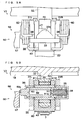
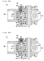
- a variable valve mechanism V1 of an internal combustion engine according to a first embodiment shown in FIGS. 1 to 7B includes a lift cam 10, a lash adjuster 20, a main arm 30, a sub arm 40, and a switching device 50, which will be described below.
- "right” refers to one side of the lateral direction of the main arm 30 and the sub arm 40
- “left” refers to the other side thereof. However, “left” and “right” may be reversed.
- the lift cam 10 is provided on a camshaft 18 extending in the lateral direction, and rotates together with the camshaft 18 according to rotation of the internal combustion engine.
- This lift cam 10 includes a base circular portion 11 having a true circular cross section, and a cam nose portion 12 protruding from the base circular portion 11.
- the lash adjuster 20 is formed by inserting a plunger 22 in a bottomed cylindrical body 21 openingupward.
- the plunger 22 can advance upward and withdraw downward.
- a high pressure oil chamber 23 is formed between the inner bottom of the body 21 and the lower end face of the plunger 22, and a low pressure oil chamber 24 is formed inside the plunger 22.
- the plunger 22 has a through hole 25 in its lower end face so that oil flows from the low pressure oil chamber 24 in the plunger 22 to the high pressure oil chamber 23 therethrough.
- a check valve 26 is disposed below the through hole 25. The check valve 26 opens the lower opening of the through hole 25 when the plunger 22 advances upward, and closes the lower opening of the through hole 25 when the plunger 22 withdraws downward.
- a leakage clearance 27 is formed between the inner peripheral surface of the body 21 and the outer peripheral surface of the plunger 22 so as to allow the oil to leak from the high pressure oil chamber 23 to the low pressure oil chamber 24 when the plunger 22 withdraws.
- the plunger 22 further has a hemispherical support portion 22a at its upper end in order to support a supported portion 33a of the main arm 30.
- the main arm 30 is a single-valve drive arm that drives only one valve 7.
- the main arm 30 is an outer arm disposed laterally outward of the sub arm 40, and is formed by sheet-metal working.
- the main arm 30 includes two side plate portions 31R, 31L arranged side by side at an interval in the lateral direction, an arm tip end 32 connecting the tip ends of the side plate portions 31R, 31L, and an arm rear end 33 connecting the rear ends of the side plate portions 31R, 31L.
- the arm tip end 32 has a pressing portion 32a on its lower surface in order to press the valve 7 downward to open the valve 7.
- the arm rear end 33 has the supported portion 33a that is continuously supported by the hemispherical support portion 22a of the plunger 22 so as to be swingable without floating upward.
- the right side plate portion 31R has an attachment hole 35a extending through its intermediate region in the longitudinal direction.
- a first cylindrical member 35 having a bottomed cylindrical shape is attached to the attachment hole 35a with the opening of the first cylindrical member 35 facing leftward and the bottom of the first cylindrical member 35 protruding rightward.
- the first cylindrical member 35 has an air vent hole 35b extending through its bottom.
- the left side plate portion 31L has an attachment hold 36a extending through its intermediate region in the longitudinal direction.
- a second cylindrical member 36 having a bottomed cylindrical shape is attached to the attachment hole 36a with the opening of the second cylindrical member 36 facing rightward and the bottom of the second cylindrical member 36 protruding leftward.
- the second cylindrical member 36 has a pin protrusion hole 36b extending through its bottom in order to allow a tip end 53a of an intervening pin 53 of the switching device 50 to protrude leftward.
- Each of the side plate portions 31R, 31L has an attachment hole 3 7a extending therethrough in a region rearward of the pressing portion 32a and forward of the first cylindrical member 35 or the second cylindrical member 36.
- a stopper 37 is attached to the attachment hole 37a so that the stopper 37 contacts the sub arm 40 from above.
- Each of the side plate portions 31R, 31L has a spring latch recess 38 in its rear end at a position above the arm rear end 33.
- Each spring latch recess 38 is recessed forward in the rear end of the side plate portion 31R, 31L so as to support a rear part 63 of a lost motion spring 60.
- Each of the side plate portions 31R, 31L has a support hole 34 extending therethrough in a region rearward of the first or second cylindrical member 35, 36 of the side plate portion 31R, 31L and forward of the supported portion 33a in order to support a support pin 47 described below.
- the sub arm 40 is an inner arm that is provided next to the main arm 30 and disposed laterally inward of the main arm 30, and is formed by sheet-metal working.
- the sub arm 40 includes two inner plate portions 41R, 41L that are arranged inward of the side plate portions 31R, 31L of the main arm 30 and side by side at an interval in the lateral direction, and a bottom plate portion 42 connecting the lower ends of the tip ends of the inner plate portions 41R, 41L.
- the bottom plate portion 42 has a weight-reducing hole 42a extending therethrough in order to reduce the weight.
- Each of the inner plate portions 41R, 41L has an attachment hole 43a extending therethrough in a region above the bottom plate portion 42 at the tip end of the inner plate portion 41R, 41L.
- a cylindrical roller shaft 43 is supported by the attachment holes 43a, 43a, and a roller 45 is rotatably supported by the roller shaft 43 via bearings 44, 44.
- the roller 45 contacts the lift cam 10.
- the center of the roller 45 is located rearward of the pressing portion 32a of the main arm 30 and forward of the swing center of the supported portion 33a.
- each of the inner plate portions 41R, 41L has a supported hole 47a extending therethrough.
- the single support pin 47 is inserted through the supported holes 47a, 47a and the support holes 34, 34 of the main arm 30, so that the rear ends of the inner plate portions 41R, 41L are swingably supported by the side plate portions 31R, 31L of the main arm 30.
- Both ends of the support pin 47 protrude on both right and left sides of the side plate portions 31R, 31L of the main arm 30, and cylindrical retaining members 48, 48 are fitted on both ends of the support pin 47.
- the center of the support pin 47 is located rearward of the center of the roller 45 and forward of the swing center of the supported portion 33a.
- the distance L1 from the center of the support pin 47 to the swing center of the supported portion 33a is 0.8 to 1.0 times the distance L2 from the center of the support pin 47 to the center of the roller 45 as viewed from the side.
- the switching device 50 is a device that switches between a coupled state where the sub arm 40 is coupled to the main arm 30 so as not to allow the sub arm 40 to swing relative to the main arm 30, and a non-coupled state where the coupling between the sub arm 40 and the main arm 30 is released.
- the switching device 50 includes a first switch pin 51, a second switch pin 52, the intervening pin 53, a shift device 56, and a return spring 58, which will be described below.
- the first switch pin 51 is a bottomed cylindrical pin, and is inserted in the first cylindrical member 35 with an opening of the first switch pin 51 facing rightward.
- the first switch pin 51 can be shifted between a coupling position where the first switch pin 51 extends from the inner side of the first cylindrical member 35 to the inner side of the roller shaft 43 and a non-coupling position where the first switch pin 51 does not extend from the inner side of the first cylindrical member 35 to the inner side of the roller shaft 43.
- the first switch pin 51 has an air vent hole 51a extending therethrough at its bottom.
- the second switch pin 52 is a cylindrical pin, and is inserted in the roller shaft 43.
- the second switch pin 52 can be shifted between a coupling position where the second switch pin 52 extends from the inner side of the roller shaft 43 to the inner side of the second cylindrical member 36 and a non-coupling position where the second switch pin 52 does not extend from the inner side of the roller shaft 43 to the inner side of the second cylindrical member 36.
- the intervening pin 53 is inserted in the second cylindrical member 36 so that its left tip end 53a having a smaller diameter than the remaining part can protrude leftward from the pin protrusion hole 36b of the second cylindrical member 36.
- the first switch pin 51, the second switch pin 52, and the intervening pin 53 are inserted through the central portion of the roller 45 when in the coupled state.
- the shift device 56 is a device that urges the tip end 53a of the intervening pin 53 rightward from the outside (the left side) of the main arm 30 and the sub arm 40 to shift the switch pins 51, 52 rightward.
- the shift device 56 is provided outside the main arm 30 and the sub arm 40, and therefore does not swing together with the main arm 30 and the sub arm 40.
- the shift device 56 includes a shift portion 57 that contacts the tip end 53a of the intervening pin 53 from the left, and a main body (not shown) that urges the shift portion 57 rightward.
- the shift device 56 may be a hydraulic device that urges the shift portion 57 rightward by an oil pressure, or may be an electromagnetic device that urges the shift portion 57 rightward by a magnetic force.
- the return spring 58 is interposed between the inner bottom surface of the first cylindrical member 35 and the inner bottom surface of the first switch pin 51, and urges the first switch pin 51 leftward by a restoring force.
- the lost motion springs 60, 60 are the springs that cause the sub arm 40 to follow the lift cam 10 when in the non-coupled state.
- the lost motion springs 60 are provided on both sides of the main arm 30 in the lateral direction, one on each side.
- Each lost motion spring 60 includes a coil portion 62 formed in a coil shape, a front portion 61 extending forward from the coil portion 62, and a rear portion 63 extending rearward from the coil portion 62.
- the coil portion 62 of each lost motion spring 60 is fitted on the outer peripheral side of the retaining member 48.
- the front portion 61 of each lost motion spring 60 contacts the lower surface of the inner plate portion 41R, 41L of the sub arm 40, and urges this lower surface upward.
- each lost motion spring 60 is fitted in the spring latch recess 38 in the rear end of the main arm 30, and urges the upper surface of the spring latch recess 38 upward.
- the lost motion springs 60, 60 press the sub arm 40 against the main arm 30 via the switch pins 51, 52 when in the coupled state, and press the sub arm 40 against the lift cam 10 when in the non-coupled state.
- variable valve mechanism V1 in the coupled state and the non-coupled state during operation of the internal combustion engine will be described below.
- the shift portion 57 of the shift device 56 does not urge the intervening pin 53 rightward.
- the first switch pin 51, the second switch pin 52, and the intervening pin 53 are therefore shifted leftward on the centerline of the roller 45 by the restoring force of the return spring 58, and the first switch pin 51 and the second switch pin 52 are placed at the coupling position.
- the sub arm 40 is not allowed to swing relative to the main arm 30. Accordingly, as shown in FIG. 7A , the main arm 30 and the sub arm 40 swing together to drive the valve 7.
- the shift portion 57 of the shift device 56 urges the intervening pin 53 rightward.
- the first switch pin 51, the second switch pin 52, and the intervening pin 53 are therefore shifted rightward on the centerline of the roller 45 against the restoring force of the return spring 58, and the first switch pin 51 and the second switch pin 52 are placed at the non-coupling position.
- the sub arm 40 is allowed to swing relative to the main arm 30. Accordingly, asshowninFIG. 7B, onlythesubarm40swings (swings independently) about the support pin 47, and driving of the valve 7 is stopped.
- the first embodiment can provide the following effects (A) to (G).
- a variable valve mechanism V2 of an internal combustion engine according to a second embodiment shown in FIGS. 8A and 8B is different from the first embodiment in that the longitudinal interval between the roller 45 and the supported portion 33a is shorter than that in the first embodiment, and that the support pin 47 is divided into a right support pin 47R and a left support pin 47L, and the outer edge of the roller 45 is placed between the right support pin 47R and the left support pin 47L.
- the second embodiment is otherwise similar to the first embodiment.
- the right support pin 47R is inserted in both the supported hole 47a in the right inner plate portion 41R of the sub arm 40 and the support hole 34 of the right side plate portion 31R of the main arm 30, thereby swingably supporting the rear end of the right inner plate portion 41R on the right side plate portion 31R.
- the left support pin 47L is inserted in both the supported hole 47a in the left inner plate portion 41L of the sub arm 40 and the support hole 34 of the left side plate portion 31L of the main arm 30, thereby swingably supporting the rear end of the left inner plate portion 41L on the left side plate portion 31L.
- the distance L1 from the center of the support pin 47R, 47L to the swing center of the supported portion 33a is about 0.9 to 1.1 times the distance L2 from the center of the support pin 47R, 47L to the center of the roller 45 as viewed from the side.
- the second embodiment can also be used in the case where the longitudinal interval between the roller 45 and the supported portion 33a so short that there is not enough space between the roller 45 and the supported portion 33a to insert the single support pin 47 as in the first embodiment therethrough.
- a variable valve mechanism V3 of an internal combustion engine according to a third embodiment shown in FIGS. 9 to 11B is different from the first embodiment in that low lift cams 15, 15 whose lift amount is lower than that of the lift cam 10 are provided on the right and left sides of the lift cam 10 on the camshaft 18, and that slide portions 39, 39 contacting the low lift cams 15, 15 are provided at the upper ends of the side plate portions 31R, 31L of the main arm 30.
- the third embodiment is otherwise similar to the first embodiment.
- each low lift cam 15 includes a base circular portion 16 having a true circular cross section, and a cam nose portion 17 protruding from the base circular portion 16.
- a protruding portion formed at the upper end of the intermediate portion in the longitudinal direction of the side plate portion 31R, 31L is formed by bending laterally outward by sheet-metal press work, and the upper surface of the slide contact portion 39 is additionally subjected to a surface treatment as required.
- variable valve mechanism of the third embodiment has the low lift cams 15, 15, driving of the valve is not stopped even in the non-coupled state, and the variable valve mechanism is brought into a low lift drive state where the valve is driven with a smaller lift amount than in the coupled state. Accordingly, the third embodiment can be used in the case where it is desired to switch the variable valve mechanism between the high lift drive state and the low lift drive state, rather than switching the variable valve mechanism between the drive state and the stopped state as in the first embodiment.
Landscapes
- Engineering & Computer Science (AREA)
- Mechanical Engineering (AREA)
- General Engineering & Computer Science (AREA)
- Valve Device For Special Equipments (AREA)
- Valve-Gear Or Valve Arrangements (AREA)
Claims (11)
- Mécanisme de soupape variable d'un moteur à combustion interne, comprenant :un bras principal (30) ayant, au niveau de son extrémité de pointe (31), une partie de pression (32a) qui comprime une soupape (7), et ayant, au niveau de son extrémité arrière (33), une partie de support (33a) qui est supportée en continu de manière oscillante par un élément de support (22) sans flotter vers le haut ;un bras auxiliaire (40) qui est disposé à proximité du bras principal (30), qui a une extrémité de pointe sur laquelle est fixé en rotation un rouleau (45) en contact avec une came (10), dans lequel un centre du rouleau (45) est positionné vers l'arrière de la partie de pression (32a) et vers l'avant d'un centre d'oscillation de la partie supportée (33a) par rapport à une direction longitudinale du bras auxiliaire (40) et du bras principal (30), et une extrémité arrière qui est supportée de manière oscillante par rapport au bras principal (30) par une broche de support (47), et dans laquelle un centre de la broche de support (47) est positionné vers l'arrière du centre du rouleau (45) par rapport à une direction longitudinale du bras auxiliaire (40) et du bras principal (30) ; etune broche de commutation (51, 52) qui peut être décalée entre une position de couplage dans laquelle le bras auxiliaire (40) est couplé au bras principal (30) afin de ne pas permettre au bras auxiliaire (40) d'osciller par rapport au bras principal (30), et une position sans couplage dans laquelle le couplage entre le bras auxiliaire (40) et le bras principal (30) est libéré, et la broche de commutation (51, 52) est insérée dans une partie centrale du rouleau (45),caractérisé en ce que :un centre de la broche de support (47) est positionné vers l'avant du centre d'oscillation de la partie supportée (33a) par rapport à une direction longitudinale du bras auxiliaire (40) et du bras principal (30).
- Mécanisme de soupape variable d'un moteur à combustion interne selon la revendication 1, dans lequel :une distance allant du centre de la broche de support (47) au centre d'oscillation de la partie supportée (33a) représente de 0,5 à 1,5 fois une distance allant du centre de la broche de support (47) au centre du rouleau (45), comme observé à partir d'un côté.
- Mécanisme de soupape variable d'un moteur à combustion interne selon la revendication 1 ou la revendication 2, dans lequel :le bras principal (30) est un bras externe positionné latéralement vers l'extérieur du bras auxiliaire (40), et le bras auxiliaire (40) est un bras interne positionné latéralement vers l'intérieur du bras principal (30), etl'élément de support (22) est un piston plongeur (22) d'un ajusteur de jeu (20) qui comprend, au niveau de son extrémité supérieure, une partie de support hémisphérique (22a) qui supporte la partie supportée (33a).
- Mécanisme de soupape variable d'un moteur à combustion interne selon la revendication 3, comprenant en outre :un dispositif de déplacement (56) qui est prévu à l'extérieur du bras principal (30) et du bras auxiliaire (40), qui déplace la broche de commutation (51, 52) et qui n'oscille pas conjointement avec le bras principal (30) ni avec le bras auxiliaire (40).
- Mécanisme de soupape variable d'un moteur à combustion interne selon la revendication 4, dans lequel :le bras principal (30) est un bras d'entraînement de soupape unique qui entraîne une seule soupape (7).
- Mécanisme de soupape variable d'un moteur à combustion interne selon la revendication 5, dans lequel :le bras principal (30) comprend deux parties de plaque latérales (31R, 31L) agencées côte à côte à un intervalle dans une direction latérale du bras principal (30), une extrémité de pointe de bras (32) raccordant les extrémités de pointe des parties de plaque latérales (31R, 31L) et prévue avec la partie de pression (32a), et une extrémité arrière de bras (33) raccordant les extrémités arrière des parties de plaque latérales (31R, 31L) et prévues avec la partie supportée (32a).
- Mécanisme de soupape variable d'un moteur à combustion interne selon la revendication 6, dans lequel :le bras auxiliaire (40) comprend deux parties de plaque internes (41R, 41L) qui sont agencées entre les parties de plaque latérales (31R, 31L) et côte à côte au niveau d'un intervalle dans une direction latérale du bras auxiliaire (40) et une partie de plaque inférieure (42) raccordant les extrémités inférieures des extrémités de pointe des parties de plaque internes (41R, 41L), le rouleau (45) est fixé entre les extrémités de pointe des parties de plaque internes (41R, 41L) positionnées au-dessus de la partie de plaque inférieure (42), et les extrémités arrière des parties de plaque internes (41R, 41L) sont supportées de manière oscillante sur les parties de plaque latérales (31R, 31L) par la broche de support (51, 52).
- Mécanisme de soupape variable d'un moteur à combustion interne selon l'une quelconque des revendications 1 à 7, dans lequel :le bras principal (30) comprend deux parties de plaque latérales (31R, 31L) agencées côte à côte à un intervalle dans une direction latérale du bras principal (30), le bras auxiliaire (40) comprend deux parties de plaque internes (41R, 41L) qui sont agencées entre les parties de plaque latérales (31R, 31L) et côte à côte à un intervalle dans une direction latérale du bras auxiliaire (40) et le rouleau (45) est fixé entre les extrémités de pointe des parties de plaque interne (41R, 41L),la broche de support (51, 52) est divisée en deux broches de support (51, 52), l'une des broches de support (51, 52) supporte, de manière oscillante, une extrémité arrière de l'une des parties de plaque interne (41R, 41L) sur une partie attenante des parties de plaque latérales (31R, 31L) et l'autre broche de support supporte de manière oscillante une extrémité arrière de l'autre partie de plaque interne sur l'autre partie de plaque latérale attenante, etun bord externe du rouleau (45) est placé entre la une broche de support et l'autre broche de support.
- Mécanisme de soupape variable d'un moteur à combustion interne selon l'une quelconque des revendications 1 à 8, dans lequel :le bras principal (30) comprend deux parties de plaque latérales (31R, 31L) agencées côte à côte à un intervalle dans une direction latérale du bras principal (30) et le bras auxiliaire (40) est placé entre les parties de plaque latérales (31R, 31L), etune partie de contact coulissante (39) qui est en contact coulissant avec une autre came (15) différente de la came (10) est formée dans une extrémité supérieure de chacune des parties de plaque latérales (31R, 31L) par usinage de tôle.
- Mécanisme de soupape variable d'un moteur à combustion interne selon la revendication 9, dans lequel :l'autre came (15) est une came à faible levage (15) ayant une quantité de levage inférieure à celle de la came (10).
- Mécanisme de soupape variable d'un moteur à combustion interne selon la revendication 9, dans lequel :l'autre came est une came de ralenti ayant uniquement un cercle de base.
Applications Claiming Priority (1)
| Application Number | Priority Date | Filing Date | Title |
|---|---|---|---|
| JP2012208136A JP5947175B2 (ja) | 2012-09-21 | 2012-09-21 | 内燃機関の可変動弁機構 |
Publications (2)
| Publication Number | Publication Date |
|---|---|
| EP2711510A1 EP2711510A1 (fr) | 2014-03-26 |
| EP2711510B1 true EP2711510B1 (fr) | 2016-11-30 |
Family
ID=49165505
Family Applications (1)
| Application Number | Title | Priority Date | Filing Date |
|---|---|---|---|
| EP13182323.9A Not-in-force EP2711510B1 (fr) | 2012-09-21 | 2013-08-30 | Mécanisme d'actionnement variable de soupapes pour moteur à combustion interne |
Country Status (3)
| Country | Link |
|---|---|
| US (1) | US8960144B2 (fr) |
| EP (1) | EP2711510B1 (fr) |
| JP (1) | JP5947175B2 (fr) |
Families Citing this family (16)
| Publication number | Priority date | Publication date | Assignee | Title |
|---|---|---|---|---|
| US20190309663A9 (en) | 2008-07-22 | 2019-10-10 | Eaton Corporation | Development of a switching roller finger follower for cylinder deactivation in internal combustion engines |
| US10415439B2 (en) | 2008-07-22 | 2019-09-17 | Eaton Intelligent Power Limited | Development of a switching roller finger follower for cylinder deactivation in internal combustion engines |
| US9228454B2 (en) | 2010-03-19 | 2016-01-05 | Eaton Coporation | Systems, methods and devices for rocker arm position sensing |
| US11181013B2 (en) | 2009-07-22 | 2021-11-23 | Eaton Intelligent Power Limited | Cylinder head arrangement for variable valve actuation rocker arm assemblies |
| US9194261B2 (en) | 2011-03-18 | 2015-11-24 | Eaton Corporation | Custom VVA rocker arms for left hand and right hand orientations |
| US9874122B2 (en) | 2010-03-19 | 2018-01-23 | Eaton Corporation | Rocker assembly having improved durability |
| US9885258B2 (en) | 2010-03-19 | 2018-02-06 | Eaton Corporation | Latch interface for a valve actuating device |
| EP3140521B1 (fr) | 2014-05-06 | 2021-03-17 | Eaton Intelligent Power Limited | Prolongateur de doigt de rouleau de désactivation pour la désactivation de cylindre avec encapsulation améliorée |
| EP3203044B1 (fr) * | 2014-10-03 | 2019-12-04 | Yamaha Hatsudoki Kabushiki Kaisha | Commande de soupape pour moteur et procédé de production de bras de culbuteur |
| JP6326348B2 (ja) | 2014-10-21 | 2018-05-16 | 株式会社オティックス | 内燃機関の可変動弁機構 |
| KR102454349B1 (ko) * | 2015-01-13 | 2022-10-14 | 이턴 코포레이션 | 스위칭 로커 암 |
| DE102016200621A1 (de) * | 2016-01-19 | 2017-07-20 | Schaeffler Technologies AG & Co. KG | Innenhebel für einen schaltbaren Schlepphebel für einen Ventiltrieb einer Brennkraftmaschine und Verfahren zur Herstellung eines Innenhebels |
| WO2018217536A2 (fr) * | 2017-05-23 | 2018-11-29 | Eaton Intelligent Power Limited | Actionneur magnétique pour linguets de galets de commutation |
| JP2019157815A (ja) | 2018-03-16 | 2019-09-19 | 株式会社オティックス | 内燃機関の可変動弁機構 |
| US10815840B2 (en) * | 2018-06-05 | 2020-10-27 | Schaeffler Technologies AG & Co. KG | Coupling assembly for switchable lever |
| WO2024160470A1 (fr) * | 2023-01-31 | 2024-08-08 | Eaton Intelligent Power Limited | Système d'actionnement électromécanique pour désactiver des levier doubles à galets |
Family Cites Families (17)
| Publication number | Priority date | Publication date | Assignee | Title |
|---|---|---|---|---|
| DE2753197A1 (de) | 1976-12-15 | 1978-06-22 | Eaton Corp | Ventilsteuervorrichtung |
| JPH04116211A (ja) * | 1990-09-05 | 1992-04-16 | Nissan Motor Co Ltd | エンジンの弁作動装置 |
| DE9406190U1 (de) * | 1994-04-14 | 1994-06-09 | INA Wälzlager Schaeffler KG, 91074 Herzogenaurach | Vorrichtung zur gleichzeitigen Betätigung von zumindest zwei Gaswechselventilen |
| JPH10212913A (ja) | 1997-01-27 | 1998-08-11 | Aisin Seiki Co Ltd | 可変バルブリフト装置 |
| DE19801964A1 (de) | 1998-01-21 | 1999-07-22 | Audi Ag | Vorrichtung zur Unterbrechung des Kraftflusses zwischen wenigstens einem Ventil und wenigstens einem Nocken einer Nockenwelle |
| US6321705B1 (en) * | 1999-10-15 | 2001-11-27 | Delphi Technologies, Inc. | Roller finger follower for valve deactivation |
| US6604498B2 (en) * | 2000-05-16 | 2003-08-12 | Delphi Technologies, Inc. | Actuation mechanism for mode-switching roller finger follower |
| DE10155800A1 (de) * | 2001-11-14 | 2003-05-22 | Ina Schaeffler Kg | Schlepphebel eines Ventiltriebs einer Brennkraftmaschine |
| US6755167B2 (en) | 2002-02-26 | 2004-06-29 | Delphi Technologies, Inc. | Two-step roller finger cam follower having spool-shaped low-lift roller |
| DE10226821A1 (de) | 2002-06-15 | 2003-12-24 | Ina Schaeffler Kg | Schlepphebel eines Ventiltriebs einer Brennkraftmaschine |
| DE102004029555A1 (de) * | 2004-06-18 | 2006-01-05 | Ina-Schaeffler Kg | Schaltbarer Schlepphebel eines Ventiltriebs einer Brennkraftmaschine |
| DE102004048289A1 (de) | 2004-10-05 | 2006-04-27 | Ina-Schaeffler Kg | Schlepphebel eines Ventiltriebs einer Brennkraftmashchine |
| JP4813399B2 (ja) | 2007-02-23 | 2011-11-09 | 株式会社オティックス | 可変動弁機構 |
| JP5090037B2 (ja) * | 2007-03-22 | 2012-12-05 | 株式会社オティックス | 可変動弁機構 |
| JP2009047111A (ja) * | 2007-08-22 | 2009-03-05 | Hitachi Ltd | 内燃機関の可変動弁装置 |
| US8215275B2 (en) * | 2010-08-13 | 2012-07-10 | Eaton Corporation | Single lobe deactivating rocker arm |
| JP5767603B2 (ja) * | 2012-05-11 | 2015-08-19 | 株式会社オティックス | 可変動弁機構 |
-
2012
- 2012-09-21 JP JP2012208136A patent/JP5947175B2/ja not_active Expired - Fee Related
-
2013
- 2013-08-30 EP EP13182323.9A patent/EP2711510B1/fr not_active Not-in-force
- 2013-09-19 US US14/032,116 patent/US8960144B2/en not_active Expired - Fee Related
Also Published As
| Publication number | Publication date |
|---|---|
| EP2711510A1 (fr) | 2014-03-26 |
| US8960144B2 (en) | 2015-02-24 |
| JP2014062500A (ja) | 2014-04-10 |
| US20140083380A1 (en) | 2014-03-27 |
| JP5947175B2 (ja) | 2016-07-06 |
Similar Documents
| Publication | Publication Date | Title |
|---|---|---|
| EP2711510B1 (fr) | Mécanisme d'actionnement variable de soupapes pour moteur à combustion interne | |
| EP1725744B1 (fr) | Ensemble de suiveur a faible friction de commutation | |
| US6691657B2 (en) | Two-step finger follower rocker arm | |
| US7942119B2 (en) | Variable valve mechanism | |
| US8813698B2 (en) | Variable valve apparatus of internal combustion engine | |
| EP2662540B1 (fr) | Mécanisme de soupape variable | |
| JP4813399B2 (ja) | 可変動弁機構 | |
| EP3314097B1 (fr) | Culbuteur de commutation pour une recirculation interne des gaz d'échappement avec commande de verrouillage simple | |
| EP3012422B1 (fr) | Mécanisme de commande de soupape variable pour moteur à combustion interne | |
| EP2733319B1 (fr) | Mécanisme de fonctionnement à vanne pour moteur à combustion interne | |
| KR102454349B1 (ko) | 스위칭 로커 암 | |
| EP3232025B1 (fr) | Mécanisme à vanne variable pour moteur à combustion interne | |
| US8336513B2 (en) | Variable tappet | |
| JP4833102B2 (ja) | 可変動弁機構 | |
| US7918201B2 (en) | Variable valve mechanism for engine | |
| EP3012421B1 (fr) | Mécanisme d'actionnement variable de soupapes pour moteur à combustion interne | |
| EP2650495B1 (fr) | Mécanisme de soupape variable | |
| JP2009209847A (ja) | 可変動弁機構 | |
| JPH0343444B2 (fr) | ||
| JP2001289019A (ja) | 内燃機関の動弁装置 | |
| JP2009091969A (ja) | 可変動弁機構 | |
| JP2008190392A (ja) | 可変動弁機構 | |
| JP2005098305A (ja) | 内燃機関の動弁装置 |
Legal Events
| Date | Code | Title | Description |
|---|---|---|---|
| PUAI | Public reference made under article 153(3) epc to a published international application that has entered the european phase |
Free format text: ORIGINAL CODE: 0009012 |
|
| AK | Designated contracting states |
Kind code of ref document: A1 Designated state(s): AL AT BE BG CH CY CZ DE DK EE ES FI FR GB GR HR HU IE IS IT LI LT LU LV MC MK MT NL NO PL PT RO RS SE SI SK SM TR |
|
| AX | Request for extension of the european patent |
Extension state: BA ME |
|
| 17P | Request for examination filed |
Effective date: 20140923 |
|
| RBV | Designated contracting states (corrected) |
Designated state(s): AL AT BE BG CH CY CZ DE DK EE ES FI FR GB GR HR HU IE IS IT LI LT LU LV MC MK MT NL NO PL PT RO RS SE SI SK SM TR |
|
| 17Q | First examination report despatched |
Effective date: 20160225 |
|
| GRAP | Despatch of communication of intention to grant a patent |
Free format text: ORIGINAL CODE: EPIDOSNIGR1 |
|
| INTG | Intention to grant announced |
Effective date: 20160630 |
|
| GRAS | Grant fee paid |
Free format text: ORIGINAL CODE: EPIDOSNIGR3 |
|
| GRAA | (expected) grant |
Free format text: ORIGINAL CODE: 0009210 |
|
| AK | Designated contracting states |
Kind code of ref document: B1 Designated state(s): AL AT BE BG CH CY CZ DE DK EE ES FI FR GB GR HR HU IE IS IT LI LT LU LV MC MK MT NL NO PL PT RO RS SE SI SK SM TR |
|
| REG | Reference to a national code |
Ref country code: CH Ref legal event code: EP Ref country code: GB Ref legal event code: FG4D |
|
| REG | Reference to a national code |
Ref country code: AT Ref legal event code: REF Ref document number: 850004 Country of ref document: AT Kind code of ref document: T Effective date: 20161215 |
|
| REG | Reference to a national code |
Ref country code: IE Ref legal event code: FG4D |
|
| REG | Reference to a national code |
Ref country code: DE Ref legal event code: R096 Ref document number: 602013014643 Country of ref document: DE |
|
| PG25 | Lapsed in a contracting state [announced via postgrant information from national office to epo] |
Ref country code: LV Free format text: LAPSE BECAUSE OF FAILURE TO SUBMIT A TRANSLATION OF THE DESCRIPTION OR TO PAY THE FEE WITHIN THE PRESCRIBED TIME-LIMIT Effective date: 20161130 |
|
| REG | Reference to a national code |
Ref country code: LT Ref legal event code: MG4D |
|
| REG | Reference to a national code |
Ref country code: NL Ref legal event code: MP Effective date: 20161130 |
|
| REG | Reference to a national code |
Ref country code: AT Ref legal event code: MK05 Ref document number: 850004 Country of ref document: AT Kind code of ref document: T Effective date: 20161130 |
|
| PG25 | Lapsed in a contracting state [announced via postgrant information from national office to epo] |
Ref country code: GR Free format text: LAPSE BECAUSE OF FAILURE TO SUBMIT A TRANSLATION OF THE DESCRIPTION OR TO PAY THE FEE WITHIN THE PRESCRIBED TIME-LIMIT Effective date: 20170301 Ref country code: NO Free format text: LAPSE BECAUSE OF FAILURE TO SUBMIT A TRANSLATION OF THE DESCRIPTION OR TO PAY THE FEE WITHIN THE PRESCRIBED TIME-LIMIT Effective date: 20170228 Ref country code: LT Free format text: LAPSE BECAUSE OF FAILURE TO SUBMIT A TRANSLATION OF THE DESCRIPTION OR TO PAY THE FEE WITHIN THE PRESCRIBED TIME-LIMIT Effective date: 20161130 Ref country code: SE Free format text: LAPSE BECAUSE OF FAILURE TO SUBMIT A TRANSLATION OF THE DESCRIPTION OR TO PAY THE FEE WITHIN THE PRESCRIBED TIME-LIMIT Effective date: 20161130 |
|
| PG25 | Lapsed in a contracting state [announced via postgrant information from national office to epo] |
Ref country code: ES Free format text: LAPSE BECAUSE OF FAILURE TO SUBMIT A TRANSLATION OF THE DESCRIPTION OR TO PAY THE FEE WITHIN THE PRESCRIBED TIME-LIMIT Effective date: 20161130 Ref country code: HR Free format text: LAPSE BECAUSE OF FAILURE TO SUBMIT A TRANSLATION OF THE DESCRIPTION OR TO PAY THE FEE WITHIN THE PRESCRIBED TIME-LIMIT Effective date: 20161130 Ref country code: FI Free format text: LAPSE BECAUSE OF FAILURE TO SUBMIT A TRANSLATION OF THE DESCRIPTION OR TO PAY THE FEE WITHIN THE PRESCRIBED TIME-LIMIT Effective date: 20161130 Ref country code: PT Free format text: LAPSE BECAUSE OF FAILURE TO SUBMIT A TRANSLATION OF THE DESCRIPTION OR TO PAY THE FEE WITHIN THE PRESCRIBED TIME-LIMIT Effective date: 20170330 Ref country code: RS Free format text: LAPSE BECAUSE OF FAILURE TO SUBMIT A TRANSLATION OF THE DESCRIPTION OR TO PAY THE FEE WITHIN THE PRESCRIBED TIME-LIMIT Effective date: 20161130 Ref country code: AT Free format text: LAPSE BECAUSE OF FAILURE TO SUBMIT A TRANSLATION OF THE DESCRIPTION OR TO PAY THE FEE WITHIN THE PRESCRIBED TIME-LIMIT Effective date: 20161130 Ref country code: PL Free format text: LAPSE BECAUSE OF FAILURE TO SUBMIT A TRANSLATION OF THE DESCRIPTION OR TO PAY THE FEE WITHIN THE PRESCRIBED TIME-LIMIT Effective date: 20161130 |
|
| PG25 | Lapsed in a contracting state [announced via postgrant information from national office to epo] |
Ref country code: NL Free format text: LAPSE BECAUSE OF FAILURE TO SUBMIT A TRANSLATION OF THE DESCRIPTION OR TO PAY THE FEE WITHIN THE PRESCRIBED TIME-LIMIT Effective date: 20161130 |
|
| REG | Reference to a national code |
Ref country code: FR Ref legal event code: PLFP Year of fee payment: 5 |
|
| PG25 | Lapsed in a contracting state [announced via postgrant information from national office to epo] |
Ref country code: CZ Free format text: LAPSE BECAUSE OF FAILURE TO SUBMIT A TRANSLATION OF THE DESCRIPTION OR TO PAY THE FEE WITHIN THE PRESCRIBED TIME-LIMIT Effective date: 20161130 Ref country code: RO Free format text: LAPSE BECAUSE OF FAILURE TO SUBMIT A TRANSLATION OF THE DESCRIPTION OR TO PAY THE FEE WITHIN THE PRESCRIBED TIME-LIMIT Effective date: 20161130 Ref country code: EE Free format text: LAPSE BECAUSE OF FAILURE TO SUBMIT A TRANSLATION OF THE DESCRIPTION OR TO PAY THE FEE WITHIN THE PRESCRIBED TIME-LIMIT Effective date: 20161130 Ref country code: SK Free format text: LAPSE BECAUSE OF FAILURE TO SUBMIT A TRANSLATION OF THE DESCRIPTION OR TO PAY THE FEE WITHIN THE PRESCRIBED TIME-LIMIT Effective date: 20161130 Ref country code: DK Free format text: LAPSE BECAUSE OF FAILURE TO SUBMIT A TRANSLATION OF THE DESCRIPTION OR TO PAY THE FEE WITHIN THE PRESCRIBED TIME-LIMIT Effective date: 20161130 |
|
| PG25 | Lapsed in a contracting state [announced via postgrant information from national office to epo] |
Ref country code: SM Free format text: LAPSE BECAUSE OF FAILURE TO SUBMIT A TRANSLATION OF THE DESCRIPTION OR TO PAY THE FEE WITHIN THE PRESCRIBED TIME-LIMIT Effective date: 20161130 Ref country code: BG Free format text: LAPSE BECAUSE OF FAILURE TO SUBMIT A TRANSLATION OF THE DESCRIPTION OR TO PAY THE FEE WITHIN THE PRESCRIBED TIME-LIMIT Effective date: 20170228 Ref country code: IT Free format text: LAPSE BECAUSE OF FAILURE TO SUBMIT A TRANSLATION OF THE DESCRIPTION OR TO PAY THE FEE WITHIN THE PRESCRIBED TIME-LIMIT Effective date: 20161130 Ref country code: BE Free format text: LAPSE BECAUSE OF FAILURE TO SUBMIT A TRANSLATION OF THE DESCRIPTION OR TO PAY THE FEE WITHIN THE PRESCRIBED TIME-LIMIT Effective date: 20161130 |
|
| REG | Reference to a national code |
Ref country code: DE Ref legal event code: R097 Ref document number: 602013014643 Country of ref document: DE |
|
| PLBE | No opposition filed within time limit |
Free format text: ORIGINAL CODE: 0009261 |
|
| STAA | Information on the status of an ep patent application or granted ep patent |
Free format text: STATUS: NO OPPOSITION FILED WITHIN TIME LIMIT |
|
| 26N | No opposition filed |
Effective date: 20170831 |
|
| PG25 | Lapsed in a contracting state [announced via postgrant information from national office to epo] |
Ref country code: SI Free format text: LAPSE BECAUSE OF FAILURE TO SUBMIT A TRANSLATION OF THE DESCRIPTION OR TO PAY THE FEE WITHIN THE PRESCRIBED TIME-LIMIT Effective date: 20161130 |
|
| REG | Reference to a national code |
Ref country code: CH Ref legal event code: PL |
|
| PG25 | Lapsed in a contracting state [announced via postgrant information from national office to epo] |
Ref country code: MC Free format text: LAPSE BECAUSE OF FAILURE TO SUBMIT A TRANSLATION OF THE DESCRIPTION OR TO PAY THE FEE WITHIN THE PRESCRIBED TIME-LIMIT Effective date: 20161130 |
|
| PG25 | Lapsed in a contracting state [announced via postgrant information from national office to epo] |
Ref country code: CH Free format text: LAPSE BECAUSE OF NON-PAYMENT OF DUE FEES Effective date: 20170831 Ref country code: LI Free format text: LAPSE BECAUSE OF NON-PAYMENT OF DUE FEES Effective date: 20170831 |
|
| REG | Reference to a national code |
Ref country code: IE Ref legal event code: MM4A |
|
| PG25 | Lapsed in a contracting state [announced via postgrant information from national office to epo] |
Ref country code: LU Free format text: LAPSE BECAUSE OF NON-PAYMENT OF DUE FEES Effective date: 20170830 |
|
| REG | Reference to a national code |
Ref country code: FR Ref legal event code: PLFP Year of fee payment: 6 |
|
| PG25 | Lapsed in a contracting state [announced via postgrant information from national office to epo] |
Ref country code: IE Free format text: LAPSE BECAUSE OF NON-PAYMENT OF DUE FEES Effective date: 20170830 |
|
| PG25 | Lapsed in a contracting state [announced via postgrant information from national office to epo] |
Ref country code: MT Free format text: LAPSE BECAUSE OF NON-PAYMENT OF DUE FEES Effective date: 20170830 |
|
| PG25 | Lapsed in a contracting state [announced via postgrant information from national office to epo] |
Ref country code: HU Free format text: LAPSE BECAUSE OF FAILURE TO SUBMIT A TRANSLATION OF THE DESCRIPTION OR TO PAY THE FEE WITHIN THE PRESCRIBED TIME-LIMIT; INVALID AB INITIO Effective date: 20130830 |
|
| PG25 | Lapsed in a contracting state [announced via postgrant information from national office to epo] |
Ref country code: CY Free format text: LAPSE BECAUSE OF NON-PAYMENT OF DUE FEES Effective date: 20161130 |
|
| PG25 | Lapsed in a contracting state [announced via postgrant information from national office to epo] |
Ref country code: MK Free format text: LAPSE BECAUSE OF FAILURE TO SUBMIT A TRANSLATION OF THE DESCRIPTION OR TO PAY THE FEE WITHIN THE PRESCRIBED TIME-LIMIT Effective date: 20161130 |
|
| PG25 | Lapsed in a contracting state [announced via postgrant information from national office to epo] |
Ref country code: TR Free format text: LAPSE BECAUSE OF FAILURE TO SUBMIT A TRANSLATION OF THE DESCRIPTION OR TO PAY THE FEE WITHIN THE PRESCRIBED TIME-LIMIT Effective date: 20161130 |
|
| PG25 | Lapsed in a contracting state [announced via postgrant information from national office to epo] |
Ref country code: AL Free format text: LAPSE BECAUSE OF FAILURE TO SUBMIT A TRANSLATION OF THE DESCRIPTION OR TO PAY THE FEE WITHIN THE PRESCRIBED TIME-LIMIT Effective date: 20161130 Ref country code: IS Free format text: LAPSE BECAUSE OF FAILURE TO SUBMIT A TRANSLATION OF THE DESCRIPTION OR TO PAY THE FEE WITHIN THE PRESCRIBED TIME-LIMIT Effective date: 20170330 |
|
| PGFP | Annual fee paid to national office [announced via postgrant information from national office to epo] |
Ref country code: FR Payment date: 20210715 Year of fee payment: 9 |
|
| PGFP | Annual fee paid to national office [announced via postgrant information from national office to epo] |
Ref country code: DE Payment date: 20210720 Year of fee payment: 9 Ref country code: GB Payment date: 20210722 Year of fee payment: 9 |
|
| REG | Reference to a national code |
Ref country code: DE Ref legal event code: R119 Ref document number: 602013014643 Country of ref document: DE |
|
| GBPC | Gb: european patent ceased through non-payment of renewal fee |
Effective date: 20220830 |
|
| PG25 | Lapsed in a contracting state [announced via postgrant information from national office to epo] |
Ref country code: FR Free format text: LAPSE BECAUSE OF NON-PAYMENT OF DUE FEES Effective date: 20220831 Ref country code: DE Free format text: LAPSE BECAUSE OF NON-PAYMENT OF DUE FEES Effective date: 20230301 |
|
| PG25 | Lapsed in a contracting state [announced via postgrant information from national office to epo] |
Ref country code: GB Free format text: LAPSE BECAUSE OF NON-PAYMENT OF DUE FEES Effective date: 20220830 |