EP2710180B1 - Bandage avec cordon composite dans la bande de roulement - Google Patents
Bandage avec cordon composite dans la bande de roulement Download PDFInfo
- Publication number
- EP2710180B1 EP2710180B1 EP12722127.3A EP12722127A EP2710180B1 EP 2710180 B1 EP2710180 B1 EP 2710180B1 EP 12722127 A EP12722127 A EP 12722127A EP 2710180 B1 EP2710180 B1 EP 2710180B1
- Authority
- EP
- European Patent Office
- Prior art keywords
- elastomer
- styrene
- thermoplastic
- tyre according
- tread
- Prior art date
- Legal status (The legal status is an assumption and is not a legal conclusion. Google has not performed a legal analysis and makes no representation as to the accuracy of the status listed.)
- Not-in-force
Links
Images


Classifications
-
- D—TEXTILES; PAPER
- D04—BRAIDING; LACE-MAKING; KNITTING; TRIMMINGS; NON-WOVEN FABRICS
- D04C—BRAIDING OR MANUFACTURE OF LACE, INCLUDING BOBBIN-NET OR CARBONISED LACE; BRAIDING MACHINES; BRAID; LACE
- D04C1/00—Braid or lace, e.g. pillow-lace; Processes for the manufacture thereof
- D04C1/06—Braid or lace serving particular purposes
- D04C1/12—Cords, lines, or tows
-
- B—PERFORMING OPERATIONS; TRANSPORTING
- B29—WORKING OF PLASTICS; WORKING OF SUBSTANCES IN A PLASTIC STATE IN GENERAL
- B29D—PRODUCING PARTICULAR ARTICLES FROM PLASTICS OR FROM SUBSTANCES IN A PLASTIC STATE
- B29D30/00—Producing pneumatic or solid tyres or parts thereof
- B29D30/06—Pneumatic tyres or parts thereof (e.g. produced by casting, moulding, compression moulding, injection moulding, centrifugal casting)
- B29D30/52—Unvulcanised treads, e.g. on used tyres; Retreading
-
- B—PERFORMING OPERATIONS; TRANSPORTING
- B60—VEHICLES IN GENERAL
- B60C—VEHICLE TYRES; TYRE INFLATION; TYRE CHANGING; CONNECTING VALVES TO INFLATABLE ELASTIC BODIES IN GENERAL; DEVICES OR ARRANGEMENTS RELATED TO TYRES
- B60C11/00—Tyre tread bands; Tread patterns; Anti-skid inserts
- B60C11/02—Replaceable treads
-
- B—PERFORMING OPERATIONS; TRANSPORTING
- B60—VEHICLES IN GENERAL
- B60C—VEHICLE TYRES; TYRE INFLATION; TYRE CHANGING; CONNECTING VALVES TO INFLATABLE ELASTIC BODIES IN GENERAL; DEVICES OR ARRANGEMENTS RELATED TO TYRES
- B60C11/00—Tyre tread bands; Tread patterns; Anti-skid inserts
- B60C11/14—Anti-skid inserts, e.g. vulcanised into the tread band
-
- B—PERFORMING OPERATIONS; TRANSPORTING
- B60—VEHICLES IN GENERAL
- B60C—VEHICLE TYRES; TYRE INFLATION; TYRE CHANGING; CONNECTING VALVES TO INFLATABLE ELASTIC BODIES IN GENERAL; DEVICES OR ARRANGEMENTS RELATED TO TYRES
- B60C9/00—Reinforcements or ply arrangement of pneumatic tyres
- B60C9/0042—Reinforcements made of synthetic materials
-
- B—PERFORMING OPERATIONS; TRANSPORTING
- B60—VEHICLES IN GENERAL
- B60C—VEHICLE TYRES; TYRE INFLATION; TYRE CHANGING; CONNECTING VALVES TO INFLATABLE ELASTIC BODIES IN GENERAL; DEVICES OR ARRANGEMENTS RELATED TO TYRES
- B60C9/00—Reinforcements or ply arrangement of pneumatic tyres
- B60C9/18—Structure or arrangement of belts or breakers, crown-reinforcing or cushioning layers
-
- C—CHEMISTRY; METALLURGY
- C08—ORGANIC MACROMOLECULAR COMPOUNDS; THEIR PREPARATION OR CHEMICAL WORKING-UP; COMPOSITIONS BASED THEREON
- C08K—Use of inorganic or non-macromolecular organic substances as compounding ingredients
- C08K3/00—Use of inorganic substances as compounding ingredients
- C08K3/34—Silicon-containing compounds
- C08K3/36—Silica
-
- D—TEXTILES; PAPER
- D02—YARNS; MECHANICAL FINISHING OF YARNS OR ROPES; WARPING OR BEAMING
- D02G—CRIMPING OR CURLING FIBRES, FILAMENTS, THREADS, OR YARNS; YARNS OR THREADS
- D02G3/00—Yarns or threads, e.g. fancy yarns; Processes or apparatus for the production thereof, not otherwise provided for
- D02G3/44—Yarns or threads characterised by the purpose for which they are designed
- D02G3/48—Tyre cords
-
- B—PERFORMING OPERATIONS; TRANSPORTING
- B29—WORKING OF PLASTICS; WORKING OF SUBSTANCES IN A PLASTIC STATE IN GENERAL
- B29D—PRODUCING PARTICULAR ARTICLES FROM PLASTICS OR FROM SUBSTANCES IN A PLASTIC STATE
- B29D30/00—Producing pneumatic or solid tyres or parts thereof
- B29D30/06—Pneumatic tyres or parts thereof (e.g. produced by casting, moulding, compression moulding, injection moulding, centrifugal casting)
- B29D30/38—Textile inserts, e.g. cord or canvas layers, for tyres; Treatment of inserts prior to building the tyre
- B29D2030/381—Textile inserts, e.g. cord or canvas layers, for tyres; Treatment of inserts prior to building the tyre the inserts incorporating reinforcing parallel cords; manufacture thereof
-
- C—CHEMISTRY; METALLURGY
- C08—ORGANIC MACROMOLECULAR COMPOUNDS; THEIR PREPARATION OR CHEMICAL WORKING-UP; COMPOSITIONS BASED THEREON
- C08K—Use of inorganic or non-macromolecular organic substances as compounding ingredients
- C08K3/00—Use of inorganic substances as compounding ingredients
- C08K3/02—Elements
- C08K3/04—Carbon
-
- C—CHEMISTRY; METALLURGY
- C08—ORGANIC MACROMOLECULAR COMPOUNDS; THEIR PREPARATION OR CHEMICAL WORKING-UP; COMPOSITIONS BASED THEREON
- C08K—Use of inorganic or non-macromolecular organic substances as compounding ingredients
- C08K7/00—Use of ingredients characterised by shape
- C08K7/02—Fibres or whiskers
Definitions
- the present invention relates to pneumatic tires, and more particularly to a tire whose tread incorporates a composite cord regrooving.
- tire tread sculptures for heavy goods vehicles are provided with circumferential, straight, zigzag or corrugated grooves, said grooves being able to be joined by grooves and / or transverse incisions.
- the circumferential grooves generally include wear indicators, small platforms of vulcanized rubber compound (or rubber) covering the bottom of these grooves for a certain circumferential length, the indicator indicating the minimum depth of tread that must legally remain on the tread in use.
- the sculptures for heavy vehicles are regrooving (operation by which one can pluck new grooves), and the tires having such sculptures carry on their flanks the English mention "Regroovable" or the symbol "U”.
- the regrooving makes it possible on the one hand to prolong the adhesion potential of the truck tire and on the other hand to significantly increase the Fac yield: from 15 to 30% depending on the case and without penalizing the possibility of retreading, which is also an essential characteristic of a truck tire. It should be added that the regrooving also allows a fuel economy, the tire having a lower rolling resistance, due to the reduced depth of the grooves in the initial state compared to those of a tire having a new state of total carving depth corresponding to the maximum regrooving depth.
- the regrooving of a groove can be performed using a heated rounded blade, often still handled by an operator. Said blade, connected to a frame which bears on the tread surface, can be used manually so as to follow fairly accurately the pattern of the groove on the surface of the tread, even in the case of a groove non-rectilinear layout.
- This regrooving operation requires a number of precautions. The first of it consists in performing the regrooving operation when there remains about 2 mm of groove depth, said depth being measured between the tread surface and the radially outer surface of the wear indicators placed at the bottom of the groove. This precaution allows a good visualization of the drawing of sculpture and thus to reproduce it without major difficulty. Knowing the remaining tread depth and the regrooving depth recommended by the tire manufacturer, it is then possible to adjust and adjust the height of the regrooving blade.
- the depths of regrooving generally indicated are theoretical depths. If they are, in the majority of cases, satisfactory, and allow to adjust theoretically the blade height to retain approximately a certain thickness of rubber between the regrooved groove bottom and the radially upper face of the crown reinforcement, the risks of too deep regrooving are not excluded. However, too much regrooving can lead to damage causing the premature destruction of the tire casing. It can also compromise the possibility of economic retreading, ie retreading where only the tread is changed. It can also, in some extreme cases, reveal, at the bottom of the new grooves after regrooving, the plies of the crown reinforcement radially underlying, which is not generally accepted by the legislation in force.
- the patent US 6,003,576 recommends, in a tire comprising a radial carcass reinforcement surmounted radially by a crown reinforcement formed of at least one ply of reinforcing elements, and a tread provided with grooves which can be regrooved, to provide the stripe portions.
- rolling bearings arranged radially beneath the regrooving grooves depth indicators, each indicator comprising at least one means indicating the minimum depth to reach for an effective regrooving and the maximum depth should in no case be exceeded.
- the depth indicators are preferably in the form of incisions of low non-zero width placed at the bottom of the groove or parallel to the direction of said groove, either perpendicular to said direction, or both simultaneously, the means indicating the minimum and maximum depth then being the geometric shape of the bottom of the depth indicator incision.
- the indicators of regrooving do not remove, despite the high mechanization and the robotization, the risk of passage of a blade of cut very close to the tablecloths of the crown reinforcement; these indicators do not remove human presence for depth settings.
- the regrooving is carried out radially under the original grooves, designed according to a new tread thickness, and not according to a tread whose thickness has greatly decreased and whose optimal tread pattern is not necessarily the design designed for the normal tread thickness.
- the document EP 1 392 497 B1 proposes a tread internally comprising spacers whose outer wall view in meridian section has a portion identical to the contour of the wall of a regrooving groove to be created.
- the spacers have the property of being anti-stick with the rubbery mixture of the tread.
- These spacers are provided with orifices to create, during the molding of the tire blank, rubber-mix bridges between the material of the regrooving groove to be created and the remainder of the tread. These rubber bridges prevent the ejection of the material of the regrooving groove to be created when it comes into contact with the ground by wear of the tread, while allowing its extraction by an operator by breaking these bridges rubber mix .
- the manufacturing process of this tread is, however, long, complex and expensive since it is necessary in particular to successively put in place in the tread blank interleaves then recoating cords.
- the documents US 1,400,301 and US 2,257,646 disclose various cable constructions or reinforcements of carcass plies.
- the cables or cords are composite cords comprising an elastomeric core and a sheath surrounding the elastomeric core.
- cord or "ring” a product of substantially constant cross-section and whose length is much greater than any other dimension
- cord regrooving a cord to be inserted into a cavity tread of a pneumatic or non-pneumatic tire being manufactured, and then removed after tread wear in use to create a circumferential regrooving groove.
- the regrooving bead after insertion into the tread forms a continuous circumferential ring.
- This ring can be rectilinear, zigzag or corrugated depending on the case.
- the subject of the invention is a pneumatic or non-pneumatic tire with a tread, characterized in that the tread comprises, in at least one internal cavity, a composite regrooving bead comprising an elastomeric core and a sheath surrounding the elastomer core. , and in that the sheath is a hollow cylindrical braid of helically interlaced and non-contiguous fibers.
- the braid of the sheath is for example formed of two sets of intersecting fibers arranged at an angle to the generatrix of the sheath. Between the non-contiguous fibers there remain spacings which give the braid of the sheath a large deformability in particular of the diameter of the sheath as a function of the extension thereof in the direction of its generator. These spacings also have the advantage of allowing, during the vulcanization of the tire in a mold, a direct contact between the elastomer core of the bead disposed in a cavity of the tread of the tire and the adjacent mixture of the tire strip. rolling and thus the creation of gum bridges ensuring a dense and homogeneous mechanical bonding of the composite recreaming cord over its entire periphery.
- the regrooving composite bead can be made by injecting the elastomeric core into the braid and then being easily incorporated into a cavity of a tread, prior to vulcanization of the tire. According to one variant, it is also possible to braid a sheath directly around an existing elastomeric core.
- the braid also has the advantage of surrounding the elastomeric core during the vulcanization of the tire and thus facilitating the maintenance of the geometry of this elastomeric core during the entire vulcanization phase.
- the mechanical bonding of the regrooving composite bead with the adjacent material of the tread is sufficient so that it is not ejected during rolling and to prevent any relative movement of this composite bead with respect to the rest of the tread. tread, movement source of friction and therefore of heat dissipation at the interface.
- the rubber bridges also have the advantage that they can be manually torn without specific tools once the composite regrooving bead is visible by wear on the tread of the tire and thus allow easy and precise extraction of the composite bead. regrooving by keeping intact the elastomeric core. The extraction of the regrooving composite bead causes the appearance of a groove similar to a regrooving groove in the tread pattern.
- the braid can be colored to facilitate the detection of the appropriate level of wear for the extraction of the composite bead.
- the formulation of the elastomer core of the recreusage composite bead is based on at least one diene elastomer.
- this composition comprises more than 30 parts by weight per hundred parts of elastomer (phr) of a charge denoted A whose particles are nanoparticles whose mean size is less than 500 ⁇ m.
- the elastomer core of the regrooving bead is based on at least one thermoplastic elastomer, the thermoplastic elastomer being a block copolymer comprising at least one unsaturated elastomer block and at least one thermoplastic block.
- the cords according to one embodiment of the invention are such that their largest dimension in any straight section is between 3 and 20 mm and preferably between 5 and 15 mm.
- cords can create after the removal of the tread grooves or furrows with an axial width of between 3 and 15 mm, this which gives back to the sculpture of the bandage an excellent capacity of evacuation of the water while rolling on wet ground.
- the cross section of the composite bead may be of any shape, in particular substantially circular, or square, or rectangular or U-shaped.
- the invention particularly relates to pneumatic tires intended to equip industrial vehicles chosen from vans, "heavy vehicles” - that is, metro, buses, road transport vehicles (trucks, tractors, trailers), off-road vehicles. the road such as agricultural or civil engineering - other transport or handling vehicles.
- the invention can also be applied to tires of motor vehicles of tourism type, SUV ( “Sport Utility Vehicles "), two wheels (including motorcycles), airplanes ...
- the regrooving cords according to the invention can be used for pneumatic tires, that is to say, inflated with air but also for non-pneumatic tires, that is to say, whose load is ensured. structurally and non-pneumatically.
- any range of values designated by the expression "between a and b" represents the range of values from more than a to less than b (i.e., terminals a and b excluded) while any range of values designated by the expression “from a to b” means the range from a to b (i.e., including the strict limits a and b).
- composition based on is meant a composition comprising the mixture and / or the reaction product of the various constituents used, some of these basic constituents being capable of or intended to react with one another, at least partly, during the various phases of manufacture of the composition, in particular during its manufacture and its crosslinking or vulcanization.
- the average size (in mass) of the nanoparticles is measured conventionally after dispersion, by deagglomeration with ultrasound, of the load to be analyzed in water or an aqueous solution containing a surfactant.
- an inorganic filler such as silica
- the measurement is carried out using an XDC X-ray centrifugal sedimentometer (X-rays Disk Centrifuge), marketed by Brookhaven Instruments, according to the following procedure.
- a gradient consisting of 15 ml of water (0.05% of a nonionic surfactant) and 1 ml of ethanol is injected into the sedimentometer disk in rotation at 8000 rpm to constitute a step gradient. Then, 0.3 ml of the carbon black slurry is injected onto the surface of the gradient; after sedimentation for 120 min, the mass distribution of particle sizes and mass mean size d w are calculated by the sedimentometer software, as indicated above.
- a first essential characteristic of the composite bead according to the invention is to comprise a sheath consisting of a hollow cylindrical braid of helically interlaced fibers not joined. This sheath surrounds the elastomeric core of the composite bead.
- the braid is for example formed of two sets of intersecting fibers arranged at an angle to the generatrix of the braid.
- the non-contiguous fibers define between them spacings which give the braid a large deformability including the diameter of the braid depending on the extension thereof in the direction of its generator.
- spacings also have the advantage of allowing, during vulcanization of the bead in a cavity of a tire tread, direct contact between the elastomeric core of the composite bead and the adjacent tread mixture and thus the creation of rubber bridges ensuring a dense and homogeneous mechanical anchoring of the cord on all its periphery.
- the geometry of the fibers of the braid and their assembly are such that the surface of the spacings is between 5 and 30% of the surface of the braid. Below 5%, the number of rubber bridges becomes insufficient to ensure good anchoring of the bead in the tread and beyond 30%, it becomes difficult to extract without special tool the strip of regrooving of the strip rolling. Very preferably the surface of the spacings is between 10 and 20% of the surface of the braid.
- These braids are extensible in diameter. They are usually braided from monofilaments of round or flattened section of thermoplastic material.
- the fibers of the braid are chosen from the group consisting of polyamides, polyesters, polysulfones, polyphenylene sulphides, poly (ether-ketones), polyetherimides, poly (amide-imides), polyimides, thermoplastic elastomers, their mixtures and their alloys.
- the polyamides may be chosen from the group of aliphatic polyamides such as polyamides 6, polyamides 6-6, and mixtures thereof.
- the polyamides may also be chosen from the group of semi-aromatic polyamides such as poly (metaxylene-adipamide) (MXD-6), polyphthalamides, copolyamides, and mixtures thereof.
- the polyesters are chosen from polyethylene terephthalates (PET), polybutylene terephthalates (PBT), polycarbonates (PC) and polyethylene naphthoates (PEN) and mixtures thereof.
- PET polyethylene terephthalates
- PBT polybutylene terephthalates
- PC polycarbonates
- PEN polyethylene naphthoates
- thermoplastic elastomers chosen from the group of polyether-block-amide (PEBA), thermoplastic polyurethanes (TPU), ether-ester copolymers (COPE), and their mixtures.
- PEBA polyether-block-amide
- TPU thermoplastic polyurethanes
- COPE ether-ester copolymers
- the ether-ester copolymers are chosen from polyester-ethers and polyester-esters.
- Such extensible braids are well known and commercially available.
- Gremco sells expandable braided tubular braids manufactured from polyamide 6.6 monofilaments under the trademark GREMFLEX ® PA6.6. Binocular observation makes it easy to determine the average area of spacings for a given area of the braid. This average value is of the order of 15% in this case (see figure 17 ).
- Gremco also sells, among many others, similar braids made from PBT polyester monofilaments under the brand name GREMFLEX ® FR.
- a second essential characteristic of the composite bead according to the invention is to comprise an elastomeric core.
- the composition of this elastomeric core is based on a diene elastomer.
- the composition comprises more than 30 pce of a charge denoted A whose particles are nanoparticles whose average mass size is less than 500 nm.
- elastomer or “diene” rubber it is to be understood in a known manner (one or more elastomers) are understood to come from at least a part (ie, a homopolymer or a copolymer) of monomers dienes (monomers carrying two carbon-carbon double bonds , conjugated or not).
- the diene elastomer of the elastomer core is preferably chosen from the group of highly unsaturated diene elastomers consisting of polybutadienes (BR), synthetic polyisoprenes (IR), natural rubber (NR), butadiene copolymers, copolymers of isoprene and mixtures of these elastomers.
- Such copolymers are more preferably selected from the group consisting of butadiene-styrene copolymers (SBR), isoprene-butadiene copolymers (BIR), isoprene-styrene copolymers (SIR) and isoprene-copolymers.
- SBIR butadiene-styrene
- butadiene-styrene-isoprene copolymers those having a styrene content of between 5% and 50% by weight and more particularly of between 10% and 40%, an isoprene content of between 15% and 60% by weight and more particularly between 20% and 50%, a butadiene content of between 5% and 50% by weight and more particularly between 20% and 40%, a content (% molar) in -1,2 units of the butadiene part of between 4% and 85%, a content (mol%) in trans-1,4 units of the butadiene part of between 6% and 80%, a content (mol%) in units -1,2 more -3,4 of the isoprenic part comprised between 5% and 70% and a content (mol%) in trans units -1,4 of the isoprenic part of between 10% and 50%, and more generally any butadiene-styrene copolymer; isoprene with a Tg of -20 ° C to -70 ° C
- the diene elastomer is predominantly (ie, for more than 50 phr) an SBR, whether it is an emulsion-prepared SBR ("ESBR") or an SBR prepared in solution (“SSBR”), or a blend (mixture) SBR / BR, SBR / NR (or SBR / IR), BR / NR (or BR / IR), or SBR / BR / NR (or SBR / BR / IR).
- SBR emulsion-prepared SBR
- SSBR SBR prepared in solution
- an SBR elastomer In the case of an SBR elastomer (ESBR or SSBR), an SBR having an average styrene content, for example between 20% and 35% by weight, or a high styrene content, for example 35 to 35% by weight, is used in particular. 45%, a vinyl ring content of the butadiene part of between 15% and 70%, a content (mol%) of trans-1,4 bonds of between 15% and 75% and a Tg of between -10 ° C. and - 55 ° C; such an SBR can be advantageously used in admixture with a BR preferably having more than 90% (mol%) of cis-1,4 bonds.
- the diene elastomer is predominantly (for more than 50 phr) an isoprene elastomer.
- isoprene elastomer is meant in known manner a homopolymer or copolymer of isoprene, in other words a diene elastomer chosen from the group consisting of natural rubber (NR), synthetic polyisoprenes (IR), different isoprene copolymers and mixtures of these elastomers.
- isoprene copolymers examples include butyl rubber - IIR), isoprene-styrene (SIR), isoprene-butadiene (BIR) or isoprene-butadiene-styrene (SBIR).
- This isoprene elastomer is preferably natural rubber or synthetic cis-1,4 polyisoprene; of these synthetic polyisoprenes, polyisoprenes having a content (mol%) of cis-1,4 bonds greater than 90%, more preferably still greater than 98%, are preferably used.
- the elastomer core comprises a blend of one (or more) diene elastomers referred to as "high Tg” having a Tg of between -70 ° C. and 0 ° C. one (or more) diene elastomers called “low Tg” having a Tg between -110 ° C and -80 ° C, more preferably between -105 ° C and -90 ° C.
- the high Tg elastomer is preferably selected from the group consisting of S-SBR, E-SBR, natural rubber, synthetic polyisoprenes (having a (mol%) content of cis-1,4 linkages of preferably greater than 95%), BIRs, SIRs, SBIRs, and mixtures of these elastomers.
- the low Tg elastomer preferably comprises butadiene units at a level (mol%) of at least 70%; it consists preferably of a polybutadiene (BR) having a content (mol%) of cis-1,4 linkages greater than 90%.
- the composition of the elastomer core comprises, for example, from 30 to 100 phr, in particular from 50 to 100 phr, of a high Tg elastomer in a blend with 0 to 70 phr, particularly from 0 to 50 phr, of a low Tg elastomer; according to another example, it comprises for all 100 pce one or more SBR prepared (s) in solution.
- the diene elastomer of the composition of the elastomer core comprises a blend of a BR (as low elastomer Tg) having a content (% molar) of cis-chains. 1.4 greater than 90%, with one or more S-SBR or E-SBR (as elastomer (s) high Tg).
- compositions formulated according to the invention may contain a single diene elastomer or a mixture of several diene elastomers, or the diene elastomers may be used in combination with any type of synthetic elastomer other than diene, or even with polymers other than elastomers for example thermoplastic polymers.
- any type of reinforcing filler known for its ability to reinforce a rubber composition which can be used for the manufacture of tire treads for example an organic filler, such as black, can be used.
- Suitable carbon blacks are all carbon blacks, especially blacks conventionally used in tire treads (so-called pneumatic grade blacks).
- the reinforcing carbon blacks of the 100, 200 or 300 series for example the N115, N134, N234, N326, N330, N339, N347 or N375 blacks, or even targeted applications, blacks of higher series (eg N660, N683, N772).
- the carbon blacks could for example already be incorporated into the isoprene elastomer in the form of a masterbatch (see for example applications WO 97/36724 or WO 99/16600 ).
- organic fillers other than carbon blacks
- any inorganic or mineral filler (regardless of its color and origin (natural or synthetic), also called “white” filler, “clear” filler even “ non-black filler” ( “non-black filler” ) as opposed to carbon black, capable of reinforcing on its own, with no other means than an intermediate coupling agent, a rubber composition intended for the manufacture of tires, in other words, able to replace, in its reinforcing function, a conventional carbon black of pneumatic grade, such a charge is generally characterized, in known manner, by the presence of hydroxyl groups (-OH) on its surface.
- -OH hydroxyl groups
- the physical state in which the reinforcing inorganic filler is present is indifferent whether in the form of powder, microbeads, granules, beads or any other suitable densified form.
- the term "reinforcing inorganic filler” also refers to mixtures of different reinforcing inorganic fillers, in particular highly dispersible siliceous and / or aluminous fillers as described below.
- Suitable reinforcing inorganic fillers are, in particular, mineral fillers of the siliceous type, in particular silica (SiO 2 ), or of the aluminous type, in particular alumina (Al 2 O 3 ).
- the silica used may be any reinforcing silica known to those skilled in the art, in particular any precipitated or fumed silica having a BET surface and a CTAB specific surface both less than 450 m 2 / g, preferably from 30 to 400 m 2 / g.
- HDS highly dispersible precipitated silicas
- the reinforcing inorganic filler used in particular if it is silica, preferably has a BET surface area of between 45 and 400 m 2 / g, more preferably between 60 and 300 m 2 / g.
- the content of total reinforcing filler A is greater than 30 phr and preferably between 40 and 100 phr; this ensures the elastomeric core of the cord a good resistance to cracking while maintaining a low hysteresis.
- the average size (in mass) of the nanoparticles is between 20 and 200 nm, more preferably between 20 and 150 nm.
- an at least bifunctional coupling agent is used in known manner to ensure a sufficient chemical and / or physical connection between the inorganic filler ( surface of its particles) and the diene elastomer, in particular organosilanes or bifunctional polyorganosiloxanes.
- Polysulphurized silanes called “symmetrical” or “asymmetrical” silanes according to their particular structure, are used, as described, for example, in the applications WO03 / 002648 (or US 2005/016651 ) and WO03 / 002649 (or US 2005/016650 ).
- polysulfurized silanes mention may be made more particularly of bis (3-trimethoxysilylpropyl) or bis (3-triethoxysilylpropyl) polysulfides.
- bis (3-triethoxysilylpropyl) tetrasulfide, abbreviated as TESPT, or bis (triethoxysilylpropyl) disulfide, abbreviated as TESPD is especially used.
- polysulfides in particular disulphides, trisulphides or tetrasulfides
- tetrasulphide of bis- monoethoxydimethylsilylpropyl as described in the patent application WO 02/083782 (or US 2004/132880 ).
- POS polyorganosiloxanes
- the content of coupling agent is preferably between 3 and 12 phr, more preferably between 4 and 9 phr.
- composition of the elastomeric core may also comprise all or part of the usual additives usually used in elastomer compositions intended for the manufacture of tires, for example pigments, protective agents such as anti-ozone waxes, chemical antiozonants anti-oxidants, anti-fatigue agents, reinforcing resins, acceptors (for example phenolic novolac resin) or methylene donors (for example HMT or H3M) as described, for example, in the application WO 02/10269 , a crosslinking system based on either sulfur, or sulfur and / or peroxide donors and / or bismaleimides, vulcanization accelerators, vulcanization activators.
- additives usually used in elastomer compositions intended for the manufacture of tires
- protective agents such as anti-ozone waxes, chemical antiozonants anti-oxidants, anti-fatigue agents, reinforcing resins, acceptors (for example phenolic novolac resin) or methylene donors (for example HMT or H3M)
- the formulation of the elastomer core may also contain, in addition to the coupling agents, coupling activators, inorganic charge-covering agents or, more generally, processing aid agents that can be used in a known manner, by means of an improvement. of the dispersion of the charge in the matrix of rubber and at a lowering of the viscosity of the compositions, to improve their ability to use in the green state, these agents being for example hydrolysable silanes such as alkylalkoxysilanes, polyols, polyethers, primary amines, secondary or tertiary, hydroxylated or hydrolyzable polyorganosiloxanes.
- these agents being for example hydrolysable silanes such as alkylalkoxysilanes, polyols, polyethers, primary amines, secondary or tertiary, hydroxylated or hydrolyzable polyorganosiloxanes.
- the elastomeric core may also comprise, as preferential non-aromatic or very weakly aromatic plasticizing agent, at least one compound chosen from the group consisting of naphthenic, paraffinic, MES, TDAE oils, ester plasticizers (for example glycerol trioleates), the hydrocarbon resins having a high Tg, preferably greater than 30 ° C, as described for example in the applications WO 2005/087859 , WO 2006/061064 and WO 2007/017060 , and mixtures of such compounds.
- the overall level of such a preferred plasticizer is preferably between 10 and 100 phr, more preferably between 20 and 80 phr, especially in a range of 10 to 50 phr.
- hydrocarbon plasticizing resins (it will be recalled that the term "resin” is reserved by definition for a solid compound), mention may be made in particular of homo- or copolymer resins of alphapinene, betapinene, dipentene or polylimonene, C5, for example C5 / styrene copolymer or C5 / C9 cut copolymer, can be used alone or in combination with plasticizing oils, for example MES or TDAE oils.
- plasticizing oils for example MES or TDAE oils.
- the composition of this elastomeric core is based on at least one thermoplastic elastomer, the thermoplastic elastomer being a block copolymer comprising at least one unsaturated elastomer block and at least one thermoplastic block.
- TPE Thermoplastic elastomer
- thermoplastic elastomers have an intermediate structure between thermoplastic polymers and elastomers. They are block copolymers, made up of rigid, thermoplastic blocks, connected by flexible blocks, elastomers.
- thermoplastic elastomer used for the implementation of this embodiment of the invention is a block copolymer whose chemical nature of the thermoplastic and elastomeric blocks can vary.
- the number-average molecular weight (denoted Mn) of the TPE is preferably between 30,000 and 500,000 g / mol, more preferably between 40,000 and 400,000 g / mol.
- Mn number-average molecular weight
- the cohesion between the elastomer chains of the TPE in particular because of its possible dilution (in the presence of an extension oil), is likely to be affected; on the other hand, an increase in the temperature of use may affect the mechanical properties, including the properties at break, resulting in reduced performance "hot”.
- a too high mass Mn can be penalizing for the implementation.
- a value in the range of 50,000 to 300,000 g / mol is particularly well suited, particularly to the use of TPE in a tire regrooving bead composition.
- the number-average molecular weight (Mn) of the TPE elastomer is determined in known manner by steric exclusion chromatography (SEC).
- SEC steric exclusion chromatography
- the sample is solubilized beforehand in tetrahydrofuran at a concentration of approximately 1 g / l; then the solution is filtered on a 0.45 ⁇ m porosity filter before injection.
- the apparatus used is a "WATERS alliance" chromatographic chain.
- the elution solvent is tetrahydrofuran, the flow rate 0.7 ml / min, the system temperature 35 ° C and the analysis time 90 min.
- a set of four WATERS columns in series, of trade names "STYRAGEL"("HMW7",”HMW6E” and two “HT6E”) is used.
- the injected volume of the solution of the polymer sample is 100 ⁇ l.
- the detector is a "WATERS 2410" differential refractometer and its associated software for the exploitation of chromatographic data is the “WATERS MILLENIUM” system.
- the calculated average molar masses relate to a calibration curve made with polystyrene standards. The conditions are adaptable by those skilled in the art.
- the TPE when reference is made to the glass transition temperature of the TPE, it is the Tg relative to the elastomeric block.
- the TPE preferably has a glass transition temperature ("Tg") which is preferably less than or equal to 25 ° C, more preferably less than or equal to 10 ° C.
- Tg glass transition temperature
- a value of Tg greater than these minima can reduce the performance of the elastomeric core of the composite bead when used at a very low temperature; for such use, the Tg of the TPE is more preferably still less than or equal to -10 ° C.
- the Tg of the TPE is greater than -100 ° C.
- the TPEs have two glass transition temperature peaks (Tg, measured according to ASTM D3418), the lowest temperature being relative to the elastomeric portion of the TPE, and the highest temperature being relative to the portion thermoplastic TPE.
- Tg glass transition temperature peaks
- the soft blocks of the TPEs are defined by a Tg lower than the ambient temperature (25 ° C), while the rigid blocks have a Tg greater than 80 ° C.
- the TPE must be provided with sufficiently incompatible blocks (that is to say different because of their mass, their polarity or their respective Tg) to maintain their own properties. elastomeric or thermoplastic block.
- TPEs can be copolymers with a small number of blocks (less than 5, typically 2 or 3), in which case these blocks have high masses, greater than 15,000 g / mol.
- These TPEs can be, for example, diblock copolymers, comprising a thermoplastic block and an elastomer block. They are often also triblock elastomers with two rigid segments connected by a flexible segment. The rigid and flexible segments can be arranged linearly, star or connected. Typically, each of these segments or blocks often contains at least more than 5, usually more than 10 units base (for example styrene units and butadiene units for a styrene / butadiene / styrene block copolymer).
- TPEs can also comprise a large number of blocks (more than 30, typically from 50 to 500) smaller, in which case these blocks have low masses, for example from 500 to 5000 g / mol, these TPEs will be called multiblock TPEs. thereafter, and are a sequence of elastomeric blocks - thermoplastic blocks.
- the TPE is in a linear form.
- TPE is a diblock copolymer: thermoplastic block / elastomeric block.
- the TPE can also be a triblock copolymer: thermoplastic block / elastomer block / thermoplastic block, that is to say a central elastomer block and two terminal thermoplastic blocks, at each of the two ends of the elastomeric block.
- the multiblock TPE can be a linear sequence of elastomeric blocks - thermoplastic blocks.
- the TPE useful for the purposes of the invention is in a star shape with at least three branches.
- the TPE may then consist of a stellate elastomer block with at least three branches and a thermoplastic block, located at the end of each of the branches of the elastomeric block.
- the number of branches of the central elastomer can vary, for example from 3 to 12, and preferably from 3 to 6.
- the TPE is in a branched or dendrimer form.
- the TPE can then consist of a connected elastomeric block or dendrimer and a thermoplastic block, located at the end of the branches of the dendrimer elastomer block.
- the elastomeric blocks of TPEs may be any elastomers known to those skilled in the art. They may be carbon chain (polyisoprene for example) or not (silicones for example). They have a Tg less than 25 ° C, preferably less than 10 ° C, more preferably less than 0 ° C and very preferably less than - 10 ° C. Also preferably, the TPE block elastomer block is greater than -100 ° C.
- elastomeric blocks with a carbon chain if the elastomeric portion of the TPE does not contain ethylenic unsaturation, it will be referred to as a saturated elastomer block. If the elastomeric block of the TPE comprises ethylenic unsaturations (that is to say carbon-carbon double bonds), then we will speak of an unsaturated or diene elastomer block.
- unsaturated elastomer blocks are chosen to allow good mechanical bonding with the adjacent mixtures of the tread by covulcanization. It should be noted that the covulcanization with the adjacent mixture of the tread can be done even if the elastomeric core does not have a clean vulcanization system.
- this elastomer block of TPE is composed mainly of a diene elastomer part.
- a majority is meant a weight ratio of the highest diene monomer relative to the total weight of the elastomer block, and preferably a weight content of more than 50%, more preferably of more than 75% and even more preferably of more than 85%. %.
- the unsaturation of the unsaturated elastomer block can come from a monomer comprising a double bond and a cyclic unsaturation, this is the case for example in polynorbornene.
- C 4 -C 14 conjugated dienes may be polymerized or copolymerized to form a diene elastomer block.
- these conjugated dienes are chosen from isoprene, butadiene, piperylene, 1-methylbutadiene, 2-methylbutadiene, 2,3-dimethyl-1,3-butadiene and 2,4-dimethyl-1 , 3-butadiene, 1,3-pentadiene, 2-methyl-1,3-pentadiene, 3-methyl-1,3-pentadiene, 4-methyl-1,3-pentadiene, 2,3-pentadiene, 1,3-dimethyl-1,3-pentadiene, 2-methyl-1,4-pentadiene, 1,3-hexadiene, 2-methyl-1,3-hexadiene, 2-methyl-1,5-hexadiene, 3-methyl-1,3-hexadiene, 4-methyl-1,3-hexadiene, 5-methyl-1,3-
- monomers polymerized to form the elastomeric portion of the TPE may be randomly copolymerized with at least one other monomer to form an elastomeric block.
- the molar fraction of polymerized monomer other than an ethylenic monomer, relative to the total number of elastomeric block units, must be such that this block retains its elastomer properties.
- the molar fraction of this other comonomer may range from 0 to 50%, more preferably from 0 to 45% and even more preferably from 0 to 40%.
- this other monomer capable of copolymerizing with the first monomer may be chosen from the ethylenic monomers as defined above (for example ethylene), the diene monomers, more particularly the conjugated diene monomers having from 4 to 14 carbon atoms as defined above (for example butadiene), the monomers of vinylaromatic type having from 8 to 20 carbon atoms as defined below or else it may be a monomer such as acetate vinyl).
- the comonomer is of vinylaromatic type, it advantageously represents a fraction in units on the total number of units of the thermoplastic block from 0 to 50%, preferably ranging from 0 to 45% and even more preferably ranging from 0 to 40%.
- vinylaromatic compounds are particularly suitable styrenic monomers mentioned above, namely methylstyrenes, para-tert-butylstyrene, chlorostyrenes, bromostyrenes, fluorostyrenes or para-hydroxy-styrene.
- the vinylaromatic comonomer is styrene.
- the elastomeric blocks of the TPE have in total a number-average molecular weight ("Mn") ranging from 25,000 g / mol to 350,000 g / mol, preferably 35,000 g at 250,000 g / mol so as to give the TPE good elastomeric properties and sufficient mechanical strength.
- Mn number-average molecular weight
- the elastomeric block may also be a block comprising several types of diene or styrenic monomers as defined above.
- the elastomeric block may also consist of several elastomeric blocks as defined above.
- the glass transition temperature characteristic (Tg) of the thermoplastic rigid block will be used. This characteristic is well known to those skilled in the art. It allows in particular to choose the temperature of industrial implementation (transformation). In the case of an amorphous polymer (or a block of polymer), the operating temperature is chosen to be substantially greater than the Tg. In the specific case of a polymer (or a polymer block) semi -crystalline, we can observe a melting temperature then higher than the glass transition temperature. In this case, it is rather the melting temperature (Tf) which makes it possible to choose the temperature of implementation of the polymer (or polymer block) considered. Thus, later, when we speak of "Tg (or Tf, if any)", we must consider that this is the temperature used to choose the temperature of implementation.
- the TPE elastomers comprise one or more thermoplastic blocks having a Tg (or Tf, where appropriate) greater than or equal to 80 ° C and consisting of ) from polymerized monomers.
- this thermoplastic block has a Tg (or Tf, if applicable) in a range of 80 ° C to 250 ° C.
- the Tg (or Tf, if appropriate) of this thermoplastic block is preferably from 80 ° C to 200 ° C, more preferably from 80 ° C to 180 ° C.
- the proportion of the thermoplastic blocks with respect to the TPE is determined firstly by the thermoplastic properties that said copolymer must exhibit.
- Thermoplastic blocks having a Tg (or Tf, if appropriate) greater than or equal to 80 ° C are preferably present in proportions sufficient to preserve the thermoplastic nature of the elastomer according to the invention.
- the minimum level of thermoplastic blocks having a Tg (or Tf, if any) greater than or equal to 80 ° C in the TPE may vary depending on the conditions of use of the copolymer.
- the ability of the TPE to deform during tire preparation can also contribute to determining the proportion of thermoplastic blocks having a Tg (or Tf, if any) greater than or equal to 80 ° C.
- Polystyrenes are obtained from styrenic monomers.
- styrene monomer is to be understood in the present description any monomer comprising styrene, unsubstituted as substituted; among the substituted styrenes may be mentioned, for example, methylstyrenes (for example o-methylstyrene, m-methylstyrene or p-methylstyrene, alpha-methylstyrene, alpha-2-dimethylstyrene, alpha-4- dimethylstyrene or diphenylethylene), para-tert-butylstyrene, chlorostyrenes (for example o-chlorostyrene, m-chlorostyrene, p-chlorostyrene, 2,4-dichlorostyrene, 2,6-dichlorostyrene or , 4,6-trichlorostyrene), bromostyrenes (eg, o
- fluorostyrenes for example, o-fluorostyrene, m-fluorostyrene, p-fluorostyrene, 2,4-difluorostyrene, 2,6-difluorostyrene or 2,4,6-trifluorostyrene
- para-hydroxy-styrene for example, o-fluorostyrene, m-fluorostyrene, p-fluorostyrene, 2,4-difluorostyrene, 2,6-difluorostyrene or 2,4,6-trifluorostyrene
- the weight content of styrene in the TPE elastomer is between 5% and 50%. Below the minimum indicated, the thermoplastic nature of the elastomer may decrease significantly while above the maximum recommended, the elasticity of the composite bead can be affected. For these reasons, the styrene content is more preferably between 10% and 40%.
- the polymerized monomer as defined above can be copolymerized with at least one other monomer so as to form a thermoplastic block having a Tg (or Tf, where appropriate) such as defined above.
- this other monomer capable of copolymerizing with the polymerized monomer may be chosen from diene monomers, more particularly conjugated diene monomers having 4 to 14 carbon atoms, and the monomers of the following type. vinylaromatic compounds having 8 to 20 carbon atoms, as defined in the part relating to the elastomeric block.
- the thermoplastic blocks of the TPE have in total a number-average molecular weight ("Mn") ranging from 5,000 g / mol to 150,000 g / mol, so as to impart to the TPE good elastomeric properties and sufficient mechanical strength and compatible with the use of tire regrooving cord.
- Mn number-average molecular weight
- thermoplastic block may also consist of several thermoplastic blocks as defined above.
- TPE is a copolymer whose elastomer part is unsaturated, and which comprises styrenic blocks and diene blocks, these diene blocks being in particular isoprene or butadiene blocks. More preferably, this TPE elastomer is chosen from the following group, consisting of diblock copolymers, linear or starred triblocks: styrene / butadiene (SB), styrene / isoprene (SI), styrene / butadiene / isoprene (SBI), styrene / butadiene / styrene (SBS), styrene / isoprene / styrene (SIS), styrene / butadiene / isoprene / styrene (SBIS) and mixtures of these copolymers.
- SB styrene / buta
- the TPE is a linear or star-shaped copolymer whose elastomer part comprises a saturated part and an unsaturated part such as for example styrene / butadiene / butylene (SBB), styrene / butadiene / butylene / styrene (SBBS) or a mixture of these copolymers.
- SBB styrene / butadiene / butylene
- SBBS styrene / butadiene / butylene / styrene
- TPE elastomers As examples of commercially available TPE elastomers, mention may be made of the SIS elastomers marketed by Kuraray, under the name “Hybrar 5125", or marketed by Kraton under the name “D1161” or else SBS elastomers. Linear marketed by Polimeri Europa under the name “Europrene SOLT 166” or star SBS marketed by Kraton under the name "D1184". Unsaturated and epoxidized TPE elastomers, such as, for example, SBS, are also known and commercially available, for example from Daicel under the name "Epofriend".
- the TPE elastomer constitutes the majority elastomer by weight; it then represents at least 50%, preferably at least 70% by weight, more preferably at least 75% by weight of all the elastomers present in the composition of the elastomeric core. Also preferably, the TPE elastomer represents at least 95% (in particular 100%) by weight of all the elastomers present in the composition of the elastomeric core.
- the amount of TPE elastomer is in a range that varies from 50 to 100 phr, preferably from 70 to 100 phr, and in particular from 75 to 100 phr. Also preferably, the composition contains from 95 to 100 phr of TPE elastomer.
- the TPE elastomer or elastomers are preferably the single elastomer (s) of the elastomeric core of the composite bead.
- thermoplastic elastomer in this second embodiment of an elastomeric core according to the invention based on a thermoplastic elastomer, the thermoplastic elastomer described above is sufficient on its own to make the composite bead according to the invention usable.
- composition of the composite bead according to this embodiment of the invention may comprise at least one (that is to say one or more) diene rubber as non-thermoplastic elastomer, this diene rubber can be used alone, or in cutting with at least one (i.e. one or more) other non-thermoplastic rubber or elastomer.
- the level of non-thermoplastic elastomer is in a range from 0 to less than 50 phr, preferably from 0 to less than 30 phr, more preferably from 0 to 25 phr, and even more preferably from 0 to 5 phr. Also preferably, the elastomer core of the composite bead according to this embodiment of the invention does not contain a non-thermoplastic elastomer.
- the diene elastomers may be diene elastomers as previously described. It is also possible to use diene elastomers called "essentially unsaturated".
- essentially unsaturated is generally understood to mean a diene elastomer derived at least in part from conjugated diene monomers having a level of units or units of diene origin (conjugated dienes) which is greater than 15% (mol%).
- conjugated diene monomers having a level of units or units of diene origin (conjugated dienes) which is greater than 15% (mol%).
- highly unsaturated diene elastomer is particularly understood to mean a diene elastomer having a content of units of diene origin (conjugated dienes) which is greater than 50%.
- diene elastomers such as certain butyl rubbers or copolymers of dienes and alpha olefins of the EPDM type can be described as "substantially saturated" diene elastomers (level of units of diene origin which are weak or very weak, always less than 15%).
- composition of the elastomer core based on at least one thermoplastic elastomer may also comprise, as additional constituents, reinforcing fillers, plasticizers and various additives as previously described.
- TPE elastomers can be used in a conventional manner for TPE, by extrusion or molding, for example from a raw material available in the form of beads or granules.
- the elastomer core based on a thermoplastic elastomer of the composite bead according to one embodiment of the invention is prepared conventionally, for example, by incorporating the various components into a twin-screw extruder, so as to effect the melting of the matrix and an incorporation of all the ingredients, then use of a die to make the profile.
- composition of the elastomer core based on a diene elastomer is manufactured in suitable mixers, using two preparation phases successive well known to those skilled in the art: a first phase of work or thermomechanical mixing (so-called “non-productive” phase) at high temperature, up to a maximum temperature between 110 ° C and 190 ° C, preferably between 130 ° C and 180 ° C, followed by a second phase of mechanical work (so-called “productive” phase) to a lower temperature, typically less than 110 ° C, for example between 40 ° C and 100 ° C, finishing phase during which is incorporated the crosslinking system.
- a first phase of work or thermomechanical mixing at high temperature, up to a maximum temperature between 110 ° C and 190 ° C, preferably between 130 ° C and 180 ° C
- a second phase of mechanical work so-called “productive” phase
- the non-productive phase is carried out in a single thermomechanical step during which all the necessary basic constituents (diene elastomer) are introduced into a suitable mixer such as a conventional internal mixer. , fillers and coupling agent if necessary, plasticizing system), then in a second step, for example after one to two minutes of mixing, the other additives, any additional coating or processing agents, with the exception of crosslinking system.
- the total mixing time in this non-productive phase is preferably between 1 and 15 minutes.
- the mixture thus obtained After cooling the mixture thus obtained, it is then incorporated in an external mixer such as a roll mill, maintained at low temperature (for example between 40 ° C and 100 ° C), the crosslinking system. The whole is then mixed (productive phase) for a few minutes, for example between 2 and 15 min.
- an external mixer such as a roll mill, maintained at low temperature (for example between 40 ° C and 100 ° C)
- the whole is then mixed (productive phase) for a few minutes, for example between 2 and 15 min.
- the crosslinking system is preferably a vulcanization system based on sulfur and an accelerator.
- Any compound that can act as accelerator for vulcanizing diene elastomers in the presence of sulfur in particular those selected from the group consisting of 2-mercaptobenzothiazyl disulfide (abbreviated "MBTS”), N-cyclohexyl-2-benzothiazyl sulfenamide (abbreviated “CBS”), N , N-dicyclohexyl-2-benzothiazyl sulphenamide (abbreviated “DCBS”), N-tert-butyl-2-benzothiazyl sulphenamide (abbreviated "TBBS”), N-tert-butyl-2-benzothiazyl sulphenimide (abbreviated as "TBSI ”) and mixtures of these compounds.
- a primary accelerator of the sulfenamide type is used.
- vulcanization activators such as zinc oxide, stearic acid, guanidine derivatives (In particular diphenylguanidine), etc.
- the sulfur content is for example between 0.5 and 3.0 phr, that of the primary accelerator between 0.5 and 5.0 phr.
- the final composition of the elastomeric core can then be calendered, for example in the form of sheets or plates. These intermediate products are then extruded in one or more operations to give the final geometry of the core of the composite bead.
- the elastomeric cores are then introduced into a sheath formed of a hollow cylindrical braid of intertwined fibers to form a composite bead.
- the complete composite cords can then be wound around reels.
- Composite cords can be used to be placed in any internal tire tread cavity for a motor vehicle such as a two-wheeled type of vehicle, tourism or industrial.
- the figure 16 has a perspective view of a composite bead 8.
- This composite bead comprises a sheath 84 consisting of a braid formed of interleaved fibers 85 and an elastomeric core 83.
- the sheath is interrupted to allow the core 83 to be viewed.
- the elastomeric core a in the example presented a circular section.
- the figure 17 is an enlargement of the figure 16 which illustrates the interlacing of the fibers 85 made of thermoplastic material such as polyamide 6.6.
- the fibers are polyamide monofilaments of flattened sections which form between them an interlacing leaving empty spacings 87. Through the spacings 87, there are the elastomer core 83. This enlargement makes it possible to estimate the total area of the spacings relative to the surface of the sheath. In the example presented, this ratio is of the order of 15%.
- the composite cords or cords are made as previously indicated prior to the formation of the rubber band and separately from the latter. It is then enough to dispose them in the furrow and to close this last one. So we bury the cords in the eraser after shaping. This method limits the amount of manufacturing defect due to the fact that it eliminates process stabilization steps at the start of each production run.
- the section is extruded and the groove formed in the section simultaneously.
- the tread or band 4 extends around the periphery of the tire between the flanks of the latter and on its carcass 5, at the periphery of the latter.
- the band 4 has an outer peripheral face 6 forming the surface by which the tire will be in contact with the ground. This face has a generally cylindrical shape with circular section.
- the band 4 comprises a main body made of rubber, which conventionally comprises a mixture of natural and synthetic elastomers as well as various products and adjuvants.
- the band 4 further comprises several cords or rods 8 which are in this case five in number, this number is not limiting.
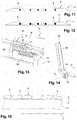
- the cords each have a wire shape, circular cross section as is the case with figures 7 , 11 and 15 or square as in the case of figures 8 and 12 .
- the cords are embedded in the body and extend at a distance from the two main external and internal faces of the band. Each cord forms a circle coaxial with the tire and extends in a plane perpendicular to the axis 3.
- the beads may have the same or different transverse profiles and may consist of identical or different materials.
- the cords are made individually, before and separately from the body, and then wound on coils 9 (see Fig. 2 ) which are then fed to the machine.
- the nose 10 of the extrusion machine comprises a frame 12 comprising two vertical uprights 14 of flat shape arranged parallel to each other and opposite and at a distance from one another. Most of the organs of the nose extend into the space arranged between the two uprights 14.
- the nose comprises a conduit 16, illustrated in particular in the right part of the figure 2 and serving for feeding the gum to be extruded to form the body.
- the nose 10 comprises a cylinder or roller 18 disposed at the downstream mouth of the duct 16 and having a cylindrical peripheral face 23 with a circular section.
- the nose further comprises a set of parts 20 forming a vault 22 which delimits with the face 23 a chamber 25 for pressurizing the material to be extruded, on which opens the conduit 16.
- the parts 20 are rigidly fixed to the frame 12, while that the roller 18 is rotatably mounted relative to the uprights 14 about its horizontal axis 24 counterclockwise on the figure 2 .
- the nose 10 comprises a profiled blade 26 extending downstream of the chamber 25 and facing the face 23 of the roller. Downstream of the blade, the nose comprises a set 30 with caster wheels 32 for introducing the cords into the grooves made beforehand, and a roller assembly 34 for closing the grooves on the cords thus arranged.
- the profiled blade 26 comprises a main body 28 of elongated form of the one to the other of the uprights 14 and rigidly fixed thereto.
- the body 28 has a lower face 36 having cavities and reliefs and intended to give shape to the upper face 6 of the tread by the effect of the passage of the rubber between the face 36 and the face 23 of the roller.
- the blade 26 further comprises a support 38 carrying plowshares 40 whose number is equal to that of the cords 8 that the band is intended to receive, five in this case.
- each of the shares 40 has a general shape in "L", the longest portion of the "L” extending in a direction close to the vertical direction and close to the radial direction to the axis 24, and being threaded into a dedicated orifice of the support 38 in which it is mounted to slide in this direction.
- the blade 26 comprises for each share 40 rigid fixing means to the body 28, formed in this case for each share by two fastening screws 42 passing through a portion of the support and clamping the share against an inner face of the support.
- This arrangement allows to adjust the position of the share relative to the body 28 in the aforementioned direction and thus to adjust the depth of the groove 44 made by the corresponding share in the band 4, for example according to the tire model being manufactured.
- the grooves 44 themselves are generated by the penetration of the base or small side of the "L" of each plow 40 into the extruded material forming the gum strip.
- the grooves are generated by the fact that the base of each plow protrudes from the face 36 of the body 28, or more precisely from certain zones of this face, as illustrated in FIG. figure 4 .
- the small side of the "L” is oriented so that the plow penetrates under the profiled part of the extrusion blade. This particular arrangement makes it possible to arrange the upstream part of the coulter in an area where the pressure within the band is not yet zero, which makes it possible to facilitate the penetration of the plow into the material of the strip as well as the quality of the molding.
- the face 36 has the right of each share a cavity 45 projecting beyond the share of each side of the latter.
- Each of these cavities makes it possible to form, on either side of the groove, respective raised beads 46 forming surplus gum. projecting from the main part of the face 6.
- Each groove therefore extends between the two associated beads 46 which are contiguous thereto.
- the number of furrows being in this case equal to five, there are ten beads.
- the grooves 44 are intended to receive the cords, then to be filled as will be seen later.
- the face 36 is also shaped to form grooves 50 in this case three in number and intended to persist visibly on the tread and the final tire, unlike the grooves 44. All the aforementioned grooves extend parallel to each other and to the longitudinal direction of the strip 4.
- the blade 26 carries, in addition, in this case, two members 52 forming deburring knives material to define the two opposite side edges of the strip. These organs are arranged opposite one another, on either side of the support 38.
- the extrusion machine comprises means 55 for receiving coils 9 on which the respective cords are wound. These means are arranged to allow the reels to unwind as manufacture progresses.
- the set 30 (see figures 6 , 9 and 10 ) comprises wheels 32 which are equal in number, in this case, to that of the cords, namely five in number.
- the wheels are identical to each other and mounted coaxially to each other about a horizontal axis 56. They extend facing the blade 26 so that a path 57 of the cords coming from the coils 9 passes between the assembly 30 and the blade 26 before insertion into the tread. During this path, the cords bear against the circumferential peripheral edge of the respective wheels 32.
- Each wheel thus serves to guide the corresponding cord to the bottom of the groove for the deposit, the wheel penetrating for this purpose within the corresponding groove.
- the wheels 32 are mounted on a common gantry fixed to the frame and whose vertical position is adjustable so as to penetrate the wheels more or less deeply into the grooves, and thus to insert the corresponding cords more or less in the latter.
- motorization for the wheels 32, the latter being rotated by the running of the tread and cords inserted in this band at the same peripheral speed as the latter.
- an intermediate guide piece such as a tube traversed along its axis by the cords for their guidance from the coils 9 to the assembly 30.
- the figure 7 illustrates the band 4 with its grooves 44 open at the bottom of which the composite cords 8 have been deposited. It is about this figure cords circular cross section with a diameter of about 4 millimeters.
- the figure 8 illustrates similarly the case of a band 4 in the grooves 44 of which are arranged composite cords 8 and having a cross section of parallelepiped shape, for example square to 4 millimeters side.
- the roller assembly 34 comprises rolling members whose number is equal to that of the cords, namely five in this case.
- the assembly 34 comprises a support 62 rigidly fixed to the uprights 14 and extending from one to the other thereof.
- Each of the members 60 comprises a mast 64 of shaped shape, received in a corresponding female orifice of the support 62 being slidably movable in the latter in its longitudinal direction which is close to the radial direction to the axis 24.
- the assembly 34 comprises for each member a clamping element 66 passing through the wall of the support 62 to clamp the mast 64 against an inner face of the support and thus immobilize the member 60 rigidly relative to the support 62 in the selected adjustment position.
- Each member 60 comprises at a lower end of the mast an arm 68 carrying two toothed rollers 70 rotatably mounted on the arm via respective rotational axes 72 coplanar but intersecting and arranged so that the rollers have an open configuration upstream by reference in the sense of scrolling the tape.
- the rollers are arranged so as to bear on the respective beads 46 associated with the groove considered so as to fold the material forming these reliefs in the groove over the cord 8 to fill the groove 44.
- the cord is thus buried , covered and embedded in the tread as illustrated in Figures 11 and 12 in both cases corresponding to Figures 7 and 8 respectively.
- the manufacturing process of the tread is carried out as follows using this machine.
- the material forming the rubber is brought into the nose by the conduit 16 along the arrow 71, then passes into the chamber 25 where it is placed. pressure before being extruded through the extrusion orifice formed by the blade 26 and the roller 18.
- the shares 40 make the longitudinal grooves 44 in the face 6, as well as the two beads 46 located on either side of each groove.
- the coulters are at the rear in an area of the machine where the pressure is reduced relative to the pressure in the chamber 25.
- the coils 9 carrying the cords are unwound and the cords guided and supported by the rollers 32 pass between them and the blade 26 to be inserted at the bottom of the respective grooves 44 in the thickness of the tread.
- the cords unwind the coils under the effect of driving the band which also drives the wheels 32.
- the coil is not braked by any actuator during its movement.
- the material forming the web is still hot and soft at this stage.
- the rollers 70 fold the material of the beads 46 into the corresponding groove, thus drowning the associated bead in the thickness of the tread.
- the furrow is thus plugged and filled.
- the figure 18 has a partial section of a tire in which has been incorporated in a rib of the tread 4 a composite bead 8 as previously described in FIGS. Figures 16 and 17 .
- the figure 19 illustrates the section after partial deshelling, that is to say a partial extraction performed with a knife, the composite bead 8 of the tread 4.
- rubber bridges crossing the spacings 87 of the sheath 84.
- These rubber bridges allow to achieve an excellent mechanical connection between the composite bead and the adjacent mixture of the tread. They are made in particular by interdiffusion and covulcanisation of the materials of the elastomeric core and the tread. There is no bonding between the fibers 85 and the material of the tread, this is what allows to extract the composite bead of the tread after partial wear thereof.
- the braid used is the GREMFLEX ® PA6.6 braid from the company Gremco of size 10. This braid has a variable diameter between 7 and 12 mm. This makes it easy to incorporate an elastomeric bead core and then, by axial tension along the generatrix of the braid, apply the braid against the periphery of the bead core.
- Pneumatic tires for a heavy vehicle of size 315/70 R 22.5 were made comprising in circumferential cavities of their tread cylindrical beads of geometry similar to the cord 8 of the figure 16 diameter of the order of 6 mm, corresponding to the composition and the sheath presented above.
- the cavities were formed in the tread and the cords were introduced into them uncured according to the previously described method.
- the cords were arranged at the same level of the tread area as the areas to be regraded in the usual way.
- the treads of the tires were then planed, that is, the tread was machined to reduce its thickness until the sheaths of the regrooving cords appeared.
- the tires were then tested for behavior on dry runways as well as on tracks with a water thickness.
- the composite cords according to the invention remained in place in their cavities. Their anchoring was sufficient to avoid any relative movement between the beads and the adjacent tread material before and after planing the treads. The cords could then be manually removed without specific tools and at one time. The grooves thus created in the tread were clean.
- the regrooving cords according to the invention thus have the advantage of allowing good control of their geometry before and after the manufacture of the tire, to give back a clean appearance of the sculpture after their extraction and to have a great facility of industrial realization.
Landscapes
- Engineering & Computer Science (AREA)
- Mechanical Engineering (AREA)
- Textile Engineering (AREA)
- Chemical & Material Sciences (AREA)
- Manufacturing & Machinery (AREA)
- Health & Medical Sciences (AREA)
- Chemical Kinetics & Catalysis (AREA)
- Medicinal Chemistry (AREA)
- Polymers & Plastics (AREA)
- Organic Chemistry (AREA)
- Compositions Of Macromolecular Compounds (AREA)
- Ropes Or Cables (AREA)
Applications Claiming Priority (2)
| Application Number | Priority Date | Filing Date | Title |
|---|---|---|---|
| FR1154338A FR2975407B1 (fr) | 2011-05-18 | 2011-05-18 | Cordon composite pour bande de roulement de bandage pneumatique |
| PCT/EP2012/059025 WO2012156404A1 (fr) | 2011-05-18 | 2012-05-15 | Bandage avec cordon composite dans la bande de roulement |
Publications (2)
| Publication Number | Publication Date |
|---|---|
| EP2710180A1 EP2710180A1 (fr) | 2014-03-26 |
| EP2710180B1 true EP2710180B1 (fr) | 2017-03-08 |
Family
ID=46125439
Family Applications (1)
| Application Number | Title | Priority Date | Filing Date |
|---|---|---|---|
| EP12722127.3A Not-in-force EP2710180B1 (fr) | 2011-05-18 | 2012-05-15 | Bandage avec cordon composite dans la bande de roulement |
Country Status (6)
| Country | Link |
|---|---|
| US (1) | US9487892B2 (OSRAM) |
| EP (1) | EP2710180B1 (OSRAM) |
| JP (1) | JP6066429B2 (OSRAM) |
| CN (1) | CN103562451B (OSRAM) |
| FR (1) | FR2975407B1 (OSRAM) |
| WO (1) | WO2012156404A1 (OSRAM) |
Families Citing this family (18)
| Publication number | Priority date | Publication date | Assignee | Title |
|---|---|---|---|---|
| FR2971188B1 (fr) | 2011-02-03 | 2013-03-08 | Michelin Soc Tech | Renfort composite gaine d'une couche de polymere auto-adherente au caoutchouc |
| FR2984228B1 (fr) | 2011-12-16 | 2016-09-30 | Soc De Tech Michelin | Bande de roulement ayant des elements de sculpture recouverts d'un assemblage de fibres impregne |
| EP3007909A4 (en) | 2013-06-15 | 2017-03-01 | Ronald Thompson | Annular ring and non-pneumatic tire |
| WO2015031226A1 (en) * | 2013-08-28 | 2015-03-05 | E. I. Du Pont De Nemours And Company | Fibrous cord and method of making |
| FR3014739B1 (fr) * | 2013-12-17 | 2016-01-01 | Michelin & Cie | Pneumatique comportant un stratifie multicouche |
| US10953696B2 (en) | 2015-02-04 | 2021-03-23 | Camso Inc | Non-pneumatic tire and other annular devices |
| CN105295216B (zh) * | 2015-06-26 | 2018-04-10 | 山东泰瑞丰新材料有限公司 | 抗疲劳、耐温免充气胎用热塑性弹性体材料及其制备方法 |
| US10821782B2 (en) * | 2015-06-29 | 2020-11-03 | Compagnie Generale Des Etablissements Michelin | Tire tread for reducing noise |
| FR3043591A1 (fr) * | 2015-11-13 | 2017-05-19 | Michelin & Cie | Composite a base de composant metallique et d'une matrice polymere fonctionnelle |
| WO2017106750A1 (en) | 2015-12-16 | 2017-06-22 | Thompson Ronald H | Track system for traction of a vehicle |
| FR3060436A1 (fr) * | 2016-12-20 | 2018-06-22 | Compagnie Generale Des Etablissements Michelin | Procede de coextrusion d’un profile caoutchouteux complexe destine a la fabrication d’un pneumatique |
| FR3060435A1 (fr) * | 2016-12-20 | 2018-06-22 | Compagnie Generale Des Etablissements Michelin | Tete de coextrusion d'un profile caoutchouteux complexe destine a la fabrication d'un pneumatique |
| US11167595B2 (en) | 2017-11-10 | 2021-11-09 | Paccar Inc | Tire tread with reduced rolling resistance |
| FR3086950B1 (fr) * | 2018-10-09 | 2020-12-25 | Hutchinson | Composition de caoutchouc pour applications dynamiques, son procede de preparation, produits l'incorporant et utilisations |
| CN111041592B (zh) * | 2019-11-06 | 2022-07-08 | 浙江恒逸石化研究院有限公司 | 一种半芳香族聚醚酰胺弹性体纤维的制备方法 |
| US11511566B2 (en) * | 2019-12-10 | 2022-11-29 | The Goodyear Tire & Rubber Company | Shear band |
| US20230030693A1 (en) * | 2019-12-16 | 2023-02-02 | Bridgestone Corporation | Tire |
| CN111469458B (zh) * | 2020-04-23 | 2022-04-26 | 广州驭轮卡科技有限公司 | 一种橡胶轮胎及其制造系统与制造方法 |
Family Cites Families (41)
| Publication number | Priority date | Publication date | Assignee | Title |
|---|---|---|---|---|
| US2148343A (en) * | 1939-02-21 | Nonskidtibe | ||
| US1400301A (en) * | 1919-12-24 | 1921-12-13 | Carlisle Tire Corp | Automobile-tire |
| US2257646A (en) * | 1939-11-09 | 1941-09-30 | Nat Standard Co | Tire casing |
| US2468304A (en) * | 1947-04-03 | 1949-04-26 | Alvin J Musselman | Tire fabric |
| US2960138A (en) | 1957-02-19 | 1960-11-15 | Robert E Burns | Tires |
| US3752206A (en) * | 1972-01-18 | 1973-08-14 | D Hough | Vented vehicle tire |
| US3951719A (en) * | 1973-01-18 | 1976-04-20 | Hough Dean R | Vehicle tire construction and method of making same |
| US4887655A (en) * | 1986-06-20 | 1989-12-19 | Bridgestone Corporation | Heavy duty-high pressure pneumatic radial tires |
| JPS6345039A (ja) * | 1986-08-12 | 1988-02-26 | Mitsubishi Rayon Co Ltd | 成形用中間材料 |
| JPH01321939A (ja) * | 1988-06-20 | 1989-12-27 | Yokohama Rubber Co Ltd:The | 空気入りタイヤ |
| US4946899A (en) | 1988-12-16 | 1990-08-07 | The University Of Akron | Thermoplastic elastomers of isobutylene and process of preparation |
| JPH03164302A (ja) * | 1989-11-22 | 1991-07-16 | Sumitomo Rubber Ind Ltd | 空気入りタイヤ |
| JPH073259B2 (ja) * | 1990-02-19 | 1995-01-18 | バンドー化学株式会社 | 繊維補強ゴム製品 |
| US5268221A (en) * | 1990-02-23 | 1993-12-07 | Bando Chemical Industries, Ltd. | Fiber reinforced rubber articles |
| SE505138C2 (sv) * | 1994-09-15 | 1997-06-30 | Fred Nordberg | Anordning vid elstängsel |
| EP0821035B1 (en) * | 1996-02-09 | 2004-10-20 | The Yokohama Rubber Co., Ltd. | Thermoplastic elastomer composition, process for the preparation thereof, hose made by using the composition, and process for the production thereof |
| CN101186724B (zh) | 1996-04-01 | 2011-01-19 | 卡伯特公司 | 新型弹性体组合物、其制备方法及设备 |
| FR2758768B1 (fr) | 1997-01-24 | 1999-03-05 | Michelin & Cie | Bande de roulement a rainures recreusables |
| AU1063099A (en) | 1997-09-30 | 1999-04-23 | Cabot Corporation | Elastomer composite blends and methods for producing them |
| EP1311600A2 (fr) | 2000-07-31 | 2003-05-21 | Société de Technologie Michelin | Bande de roulement pour pneumatique |
| EP1326871B1 (fr) | 2000-10-13 | 2006-02-01 | Société de Technologie Michelin | Organosilane polyfonctionnel utilisable comme agent de couplage et son procede d'obtention |
| JP4041734B2 (ja) | 2000-10-13 | 2008-01-30 | ソシエテ ド テクノロジー ミシュラン | カップリング剤として多官能性オルガノシランを含むゴム組成物 |
| FR2823215B1 (fr) | 2001-04-10 | 2005-04-08 | Michelin Soc Tech | Pneumatique et bande de roulement de pneumatique comportant a titre d'agent de couplage un tetrasulfure de bis-alkoxysilane |
| WO2002090094A1 (fr) | 2001-05-03 | 2002-11-14 | Societe De Technologie Michelin | Bande de roulement recreusable pour pneumatiques et procedes pour l'obtenir |
| CN1547601B (zh) | 2001-06-28 | 2012-09-05 | 米其林技术公司 | 采用具有低比表面积的二氧化硅增强的轮胎胎面 |
| WO2003002649A1 (fr) | 2001-06-28 | 2003-01-09 | Societe De Technologie Michelin | Bande de roulement pour pneumatique renforcee d'une silice a tres basse surface specifique |
| KR20040030095A (ko) | 2001-08-13 | 2004-04-08 | 소시에떼 드 테크놀로지 미쉐린 | 강화용 충전제로서 특정한 실리콘을 포함하는 타이어용디엔 고무 조성물 |
| JP2004339631A (ja) * | 2003-05-14 | 2004-12-02 | Atsuki Ushigome | 組紐および該組紐の製造方法 |
| FR2866028B1 (fr) | 2004-02-11 | 2006-03-24 | Michelin Soc Tech | Systeme plastifiant pour composition de caoutchouc |
| FR2877348B1 (fr) | 2004-10-28 | 2007-01-12 | Michelin Soc Tech | Systeme plastifiant pour composition de caoutchouc |
| FR2880349B1 (fr) | 2004-12-31 | 2009-03-06 | Michelin Soc Tech | Nanoparticules de polyvinylaromatique fonctionnalise |
| FR2880354B1 (fr) | 2004-12-31 | 2007-03-02 | Michelin Soc Tech | Composition elastomerique renforcee d'une charge de polyvinylaromatique fonctionnalise |
| FR2886304B1 (fr) | 2005-05-26 | 2007-08-10 | Michelin Soc Tech | Composition de caoutchouc pour pneumatique comportant un systeme de couplage organosilicique |
| FR2886305B1 (fr) | 2005-05-26 | 2007-08-10 | Michelin Soc Tech | Composition de caoutchouc pour pneumatique comportant un agent de couplage organosilicique et un agent de recouvrement de charge inorganique |
| FR2886306B1 (fr) | 2005-05-26 | 2007-07-06 | Michelin Soc Tech | Composition de caoutchouc pour pneumatique comportant un agent de couplage organosiloxane |
| PL1743964T3 (pl) * | 2005-07-15 | 2009-04-30 | Teijin Aramid Bv | Kord |
| FR2889538B1 (fr) | 2005-08-08 | 2007-09-14 | Michelin Soc Tech | Systeme plastifiant pour compsition de caoutchouc. |
| US20070144641A1 (en) | 2005-12-22 | 2007-06-28 | Nguyen Gia V | Method of forming a tire |
| JP4814979B2 (ja) * | 2009-06-12 | 2011-11-16 | 住友ゴム工業株式会社 | タイヤ用コード及びそれを用いた空気入りタイヤ |
| FR2959960B1 (fr) * | 2010-05-11 | 2014-05-16 | Michelin Soc Tech | Procede de realisation d'une bande de roulement pour un pneumatique de vehicule |
| FR2964344B1 (fr) | 2010-09-02 | 2012-08-31 | Michelin Soc Tech | Bandage pneumatique avec une bande de roulement comportant un materiau de remplissage degradable |
-
2011
- 2011-05-18 FR FR1154338A patent/FR2975407B1/fr active Active
-
2012
- 2012-05-15 WO PCT/EP2012/059025 patent/WO2012156404A1/fr not_active Ceased
- 2012-05-15 US US14/118,298 patent/US9487892B2/en not_active Expired - Fee Related
- 2012-05-15 EP EP12722127.3A patent/EP2710180B1/fr not_active Not-in-force
- 2012-05-15 CN CN201280023718.1A patent/CN103562451B/zh not_active Expired - Fee Related
- 2012-05-15 JP JP2014510778A patent/JP6066429B2/ja not_active Expired - Fee Related
Non-Patent Citations (1)
| Title |
|---|
| None * |
Also Published As
| Publication number | Publication date |
|---|---|
| CN103562451A (zh) | 2014-02-05 |
| JP6066429B2 (ja) | 2017-01-25 |
| JP2014518807A (ja) | 2014-08-07 |
| FR2975407A1 (fr) | 2012-11-23 |
| CN103562451B (zh) | 2016-09-14 |
| WO2012156404A1 (fr) | 2012-11-22 |
| FR2975407B1 (fr) | 2014-11-28 |
| US20140090548A1 (en) | 2014-04-03 |
| US9487892B2 (en) | 2016-11-08 |
| EP2710180A1 (fr) | 2014-03-26 |
Similar Documents
| Publication | Publication Date | Title |
|---|---|---|
| EP2710180B1 (fr) | Bandage avec cordon composite dans la bande de roulement | |
| EP2790925B1 (fr) | Bande de roulement ayant des éléments de sculpture recouverts d'un assemblage de fibres imprégnées | |
| EP2709838B1 (fr) | Cordon composite caoutchouteux pour bande de roulement de bandage pneumatique | |
| EP2834088B1 (fr) | Procédé de rechapage d'un pneumatique dont la zone sommet est pourvue d'une sous-couche comportant un élastomère thermoplastique | |
| EP2648924B1 (fr) | Bande de roulement pour pneumatique | |
| EP2834297B1 (fr) | Pneumatique dont la zone sommet est pourvue d'une sous-couche comportant un élastomère thermoplastique | |
| EP3310586B1 (fr) | Pneumatique pour vehicules destines a porter de lourdes charges | |
| EP2790910B1 (fr) | Bandage pneumatique avec une bande de roulement comportant un feutre imprégné | |
| EP2707232A1 (fr) | Pneumatique pourvu d'une bande de roulement comprenant un elastomere thermoplastique | |
| WO2015091933A1 (fr) | Pneumatique pour véhicules destinés a porter de lourdes charges | |
| EP3362270B1 (fr) | Pneumatique comprenant une bande de roulement reticulée par bombardement électronique | |
| EP3083812B1 (fr) | Pneu dont la bande de roulement comporte des elements de sculpture avec des parois laterales rigides comportant des microparticules d'oxyde ou carbure metallique | |
| EP3083810B1 (fr) | Pneu dont la bande de roulement comporte des elements de sculpture avec des parois laterales rigides comportant un caoutchouc thermo-expansible a l'etat cru, ou caoutchouc mousse a l'etat cuit | |
| EP3083811B1 (fr) | Pneu dont la bande de roulement comporte des elements de sculpture avec des parois laterales rigides contenant des microparticules hydrosolubles | |
| WO2013087873A1 (fr) | Bandage pneumatique comportant un cordon composite de recreusage |
Legal Events
| Date | Code | Title | Description |
|---|---|---|---|
| PUAI | Public reference made under article 153(3) epc to a published international application that has entered the european phase |
Free format text: ORIGINAL CODE: 0009012 |
|
| 17P | Request for examination filed |
Effective date: 20131218 |
|
| AK | Designated contracting states |
Kind code of ref document: A1 Designated state(s): AL AT BE BG CH CY CZ DE DK EE ES FI FR GB GR HR HU IE IS IT LI LT LU LV MC MK MT NL NO PL PT RO RS SE SI SK SM TR |
|
| DAX | Request for extension of the european patent (deleted) | ||
| 17Q | First examination report despatched |
Effective date: 20140929 |
|
| GRAP | Despatch of communication of intention to grant a patent |
Free format text: ORIGINAL CODE: EPIDOSNIGR1 |
|
| INTG | Intention to grant announced |
Effective date: 20161116 |
|
| GRAS | Grant fee paid |
Free format text: ORIGINAL CODE: EPIDOSNIGR3 |
|
| GRAA | (expected) grant |
Free format text: ORIGINAL CODE: 0009210 |
|
| AK | Designated contracting states |
Kind code of ref document: B1 Designated state(s): AL AT BE BG CH CY CZ DE DK EE ES FI FR GB GR HR HU IE IS IT LI LT LU LV MC MK MT NL NO PL PT RO RS SE SI SK SM TR |
|
| REG | Reference to a national code |
Ref country code: GB Ref legal event code: FG4D Free format text: NOT ENGLISH |
|
| REG | Reference to a national code |
Ref country code: CH Ref legal event code: EP Ref country code: AT Ref legal event code: REF Ref document number: 873618 Country of ref document: AT Kind code of ref document: T Effective date: 20170315 |
|
| REG | Reference to a national code |
Ref country code: IE Ref legal event code: FG4D Free format text: LANGUAGE OF EP DOCUMENT: FRENCH |
|
| REG | Reference to a national code |
Ref country code: DE Ref legal event code: R096 Ref document number: 602012029555 Country of ref document: DE |
|
| REG | Reference to a national code |
Ref country code: FR Ref legal event code: PLFP Year of fee payment: 6 |
|
| REG | Reference to a national code |
Ref country code: LT Ref legal event code: MG4D |
|
| REG | Reference to a national code |
Ref country code: NL Ref legal event code: MP Effective date: 20170308 |
|
| PG25 | Lapsed in a contracting state [announced via postgrant information from national office to epo] |
Ref country code: HR Free format text: LAPSE BECAUSE OF FAILURE TO SUBMIT A TRANSLATION OF THE DESCRIPTION OR TO PAY THE FEE WITHIN THE PRESCRIBED TIME-LIMIT Effective date: 20170308 Ref country code: GR Free format text: LAPSE BECAUSE OF FAILURE TO SUBMIT A TRANSLATION OF THE DESCRIPTION OR TO PAY THE FEE WITHIN THE PRESCRIBED TIME-LIMIT Effective date: 20170609 Ref country code: NO Free format text: LAPSE BECAUSE OF FAILURE TO SUBMIT A TRANSLATION OF THE DESCRIPTION OR TO PAY THE FEE WITHIN THE PRESCRIBED TIME-LIMIT Effective date: 20170608 Ref country code: LT Free format text: LAPSE BECAUSE OF FAILURE TO SUBMIT A TRANSLATION OF THE DESCRIPTION OR TO PAY THE FEE WITHIN THE PRESCRIBED TIME-LIMIT Effective date: 20170308 Ref country code: FI Free format text: LAPSE BECAUSE OF FAILURE TO SUBMIT A TRANSLATION OF THE DESCRIPTION OR TO PAY THE FEE WITHIN THE PRESCRIBED TIME-LIMIT Effective date: 20170308 |
|
| REG | Reference to a national code |
Ref country code: AT Ref legal event code: MK05 Ref document number: 873618 Country of ref document: AT Kind code of ref document: T Effective date: 20170308 |
|
| PG25 | Lapsed in a contracting state [announced via postgrant information from national office to epo] |
Ref country code: ES Free format text: LAPSE BECAUSE OF FAILURE TO SUBMIT A TRANSLATION OF THE DESCRIPTION OR TO PAY THE FEE WITHIN THE PRESCRIBED TIME-LIMIT Effective date: 20170308 Ref country code: SE Free format text: LAPSE BECAUSE OF FAILURE TO SUBMIT A TRANSLATION OF THE DESCRIPTION OR TO PAY THE FEE WITHIN THE PRESCRIBED TIME-LIMIT Effective date: 20170308 Ref country code: LU Free format text: LAPSE BECAUSE OF NON-PAYMENT OF DUE FEES Effective date: 20170531 Ref country code: RS Free format text: LAPSE BECAUSE OF FAILURE TO SUBMIT A TRANSLATION OF THE DESCRIPTION OR TO PAY THE FEE WITHIN THE PRESCRIBED TIME-LIMIT Effective date: 20170308 Ref country code: BG Free format text: LAPSE BECAUSE OF FAILURE TO SUBMIT A TRANSLATION OF THE DESCRIPTION OR TO PAY THE FEE WITHIN THE PRESCRIBED TIME-LIMIT Effective date: 20170608 Ref country code: LV Free format text: LAPSE BECAUSE OF FAILURE TO SUBMIT A TRANSLATION OF THE DESCRIPTION OR TO PAY THE FEE WITHIN THE PRESCRIBED TIME-LIMIT Effective date: 20170308 |
|
| PG25 | Lapsed in a contracting state [announced via postgrant information from national office to epo] |
Ref country code: NL Free format text: LAPSE BECAUSE OF FAILURE TO SUBMIT A TRANSLATION OF THE DESCRIPTION OR TO PAY THE FEE WITHIN THE PRESCRIBED TIME-LIMIT Effective date: 20170308 |
|
| PG25 | Lapsed in a contracting state [announced via postgrant information from national office to epo] |
Ref country code: IT Free format text: LAPSE BECAUSE OF FAILURE TO SUBMIT A TRANSLATION OF THE DESCRIPTION OR TO PAY THE FEE WITHIN THE PRESCRIBED TIME-LIMIT Effective date: 20170308 Ref country code: EE Free format text: LAPSE BECAUSE OF FAILURE TO SUBMIT A TRANSLATION OF THE DESCRIPTION OR TO PAY THE FEE WITHIN THE PRESCRIBED TIME-LIMIT Effective date: 20170308 Ref country code: CZ Free format text: LAPSE BECAUSE OF FAILURE TO SUBMIT A TRANSLATION OF THE DESCRIPTION OR TO PAY THE FEE WITHIN THE PRESCRIBED TIME-LIMIT Effective date: 20170308 Ref country code: RO Free format text: LAPSE BECAUSE OF FAILURE TO SUBMIT A TRANSLATION OF THE DESCRIPTION OR TO PAY THE FEE WITHIN THE PRESCRIBED TIME-LIMIT Effective date: 20170308 Ref country code: AT Free format text: LAPSE BECAUSE OF FAILURE TO SUBMIT A TRANSLATION OF THE DESCRIPTION OR TO PAY THE FEE WITHIN THE PRESCRIBED TIME-LIMIT Effective date: 20170308 Ref country code: SK Free format text: LAPSE BECAUSE OF FAILURE TO SUBMIT A TRANSLATION OF THE DESCRIPTION OR TO PAY THE FEE WITHIN THE PRESCRIBED TIME-LIMIT Effective date: 20170308 |
|
| PG25 | Lapsed in a contracting state [announced via postgrant information from national office to epo] |
Ref country code: PT Free format text: LAPSE BECAUSE OF FAILURE TO SUBMIT A TRANSLATION OF THE DESCRIPTION OR TO PAY THE FEE WITHIN THE PRESCRIBED TIME-LIMIT Effective date: 20170710 Ref country code: SM Free format text: LAPSE BECAUSE OF FAILURE TO SUBMIT A TRANSLATION OF THE DESCRIPTION OR TO PAY THE FEE WITHIN THE PRESCRIBED TIME-LIMIT Effective date: 20170308 Ref country code: IS Free format text: LAPSE BECAUSE OF FAILURE TO SUBMIT A TRANSLATION OF THE DESCRIPTION OR TO PAY THE FEE WITHIN THE PRESCRIBED TIME-LIMIT Effective date: 20170708 Ref country code: PL Free format text: LAPSE BECAUSE OF FAILURE TO SUBMIT A TRANSLATION OF THE DESCRIPTION OR TO PAY THE FEE WITHIN THE PRESCRIBED TIME-LIMIT Effective date: 20170308 |
|
| REG | Reference to a national code |
Ref country code: DE Ref legal event code: R097 Ref document number: 602012029555 Country of ref document: DE |
|
| REG | Reference to a national code |
Ref country code: CH Ref legal event code: PL |
|
| PLBE | No opposition filed within time limit |
Free format text: ORIGINAL CODE: 0009261 |
|
| STAA | Information on the status of an ep patent application or granted ep patent |
Free format text: STATUS: NO OPPOSITION FILED WITHIN TIME LIMIT |
|
| PG25 | Lapsed in a contracting state [announced via postgrant information from national office to epo] |
Ref country code: MC Free format text: LAPSE BECAUSE OF FAILURE TO SUBMIT A TRANSLATION OF THE DESCRIPTION OR TO PAY THE FEE WITHIN THE PRESCRIBED TIME-LIMIT Effective date: 20170308 Ref country code: DK Free format text: LAPSE BECAUSE OF FAILURE TO SUBMIT A TRANSLATION OF THE DESCRIPTION OR TO PAY THE FEE WITHIN THE PRESCRIBED TIME-LIMIT Effective date: 20170308 |
|
| 26N | No opposition filed |
Effective date: 20171211 |
|
| REG | Reference to a national code |
Ref country code: IE Ref legal event code: MM4A |
|
| GBPC | Gb: european patent ceased through non-payment of renewal fee |
Effective date: 20170608 |
|
| PG25 | Lapsed in a contracting state [announced via postgrant information from national office to epo] |
Ref country code: LI Free format text: LAPSE BECAUSE OF NON-PAYMENT OF DUE FEES Effective date: 20170531 Ref country code: CH Free format text: LAPSE BECAUSE OF NON-PAYMENT OF DUE FEES Effective date: 20170531 Ref country code: SI Free format text: LAPSE BECAUSE OF FAILURE TO SUBMIT A TRANSLATION OF THE DESCRIPTION OR TO PAY THE FEE WITHIN THE PRESCRIBED TIME-LIMIT Effective date: 20170308 |
|
| PG25 | Lapsed in a contracting state [announced via postgrant information from national office to epo] |
Ref country code: LU Free format text: LAPSE BECAUSE OF NON-PAYMENT OF DUE FEES Effective date: 20170515 |
|
| REG | Reference to a national code |
Ref country code: BE Ref legal event code: MM Effective date: 20170531 |
|
| PG25 | Lapsed in a contracting state [announced via postgrant information from national office to epo] |
Ref country code: GB Free format text: LAPSE BECAUSE OF NON-PAYMENT OF DUE FEES Effective date: 20170608 Ref country code: IE Free format text: LAPSE BECAUSE OF NON-PAYMENT OF DUE FEES Effective date: 20170515 |
|
| REG | Reference to a national code |
Ref country code: FR Ref legal event code: PLFP Year of fee payment: 7 |
|
| PGFP | Annual fee paid to national office [announced via postgrant information from national office to epo] |
Ref country code: DE Payment date: 20180522 Year of fee payment: 7 |
|
| PG25 | Lapsed in a contracting state [announced via postgrant information from national office to epo] |
Ref country code: BE Free format text: LAPSE BECAUSE OF NON-PAYMENT OF DUE FEES Effective date: 20170531 |
|
| PGFP | Annual fee paid to national office [announced via postgrant information from national office to epo] |
Ref country code: FR Payment date: 20180522 Year of fee payment: 7 |
|
| PG25 | Lapsed in a contracting state [announced via postgrant information from national office to epo] |
Ref country code: MT Free format text: LAPSE BECAUSE OF FAILURE TO SUBMIT A TRANSLATION OF THE DESCRIPTION OR TO PAY THE FEE WITHIN THE PRESCRIBED TIME-LIMIT Effective date: 20170308 |
|
| PG25 | Lapsed in a contracting state [announced via postgrant information from national office to epo] |
Ref country code: HU Free format text: LAPSE BECAUSE OF FAILURE TO SUBMIT A TRANSLATION OF THE DESCRIPTION OR TO PAY THE FEE WITHIN THE PRESCRIBED TIME-LIMIT; INVALID AB INITIO Effective date: 20120515 |
|
| PG25 | Lapsed in a contracting state [announced via postgrant information from national office to epo] |
Ref country code: CY Free format text: LAPSE BECAUSE OF NON-PAYMENT OF DUE FEES Effective date: 20170308 |
|
| PG25 | Lapsed in a contracting state [announced via postgrant information from national office to epo] |
Ref country code: MK Free format text: LAPSE BECAUSE OF FAILURE TO SUBMIT A TRANSLATION OF THE DESCRIPTION OR TO PAY THE FEE WITHIN THE PRESCRIBED TIME-LIMIT Effective date: 20170308 |
|
| REG | Reference to a national code |
Ref country code: DE Ref legal event code: R119 Ref document number: 602012029555 Country of ref document: DE |
|
| PG25 | Lapsed in a contracting state [announced via postgrant information from national office to epo] |
Ref country code: TR Free format text: LAPSE BECAUSE OF FAILURE TO SUBMIT A TRANSLATION OF THE DESCRIPTION OR TO PAY THE FEE WITHIN THE PRESCRIBED TIME-LIMIT Effective date: 20170308 |
|
| PG25 | Lapsed in a contracting state [announced via postgrant information from national office to epo] |
Ref country code: DE Free format text: LAPSE BECAUSE OF NON-PAYMENT OF DUE FEES Effective date: 20191203 |
|
| PG25 | Lapsed in a contracting state [announced via postgrant information from national office to epo] |
Ref country code: FR Free format text: LAPSE BECAUSE OF NON-PAYMENT OF DUE FEES Effective date: 20190531 |
|
| PG25 | Lapsed in a contracting state [announced via postgrant information from national office to epo] |
Ref country code: AL Free format text: LAPSE BECAUSE OF FAILURE TO SUBMIT A TRANSLATION OF THE DESCRIPTION OR TO PAY THE FEE WITHIN THE PRESCRIBED TIME-LIMIT Effective date: 20170308 |