EP2709423B1 - Dispositif de champ de cuisson - Google Patents
Dispositif de champ de cuisson Download PDFInfo
- Publication number
- EP2709423B1 EP2709423B1 EP13182904.6A EP13182904A EP2709423B1 EP 2709423 B1 EP2709423 B1 EP 2709423B1 EP 13182904 A EP13182904 A EP 13182904A EP 2709423 B1 EP2709423 B1 EP 2709423B1
- Authority
- EP
- European Patent Office
- Prior art keywords
- unit
- cooking
- control
- rotary
- cooking zone
- Prior art date
- Legal status (The legal status is an assumption and is not a legal conclusion. Google has not performed a legal analysis and makes no representation as to the accuracy of the status listed.)
- Active
Links
- 238000010411 cooking Methods 0.000 claims description 136
- 238000010438 heat treatment Methods 0.000 claims description 51
- 238000000034 method Methods 0.000 claims description 8
- 230000008859 change Effects 0.000 claims description 5
- 230000006698 induction Effects 0.000 description 12
- 230000005611 electricity Effects 0.000 description 7
- 230000004044 response Effects 0.000 description 6
- 239000011159 matrix material Substances 0.000 description 4
- 230000006870 function Effects 0.000 description 3
- 230000001105 regulatory effect Effects 0.000 description 3
- 239000000126 substance Substances 0.000 description 3
- 239000003086 colorant Substances 0.000 description 2
- 230000003068 static effect Effects 0.000 description 2
- 230000009471 action Effects 0.000 description 1
- 230000004913 activation Effects 0.000 description 1
- 230000033228 biological regulation Effects 0.000 description 1
- 230000001276 controlling effect Effects 0.000 description 1
- 230000007547 defect Effects 0.000 description 1
- 230000001419 dependent effect Effects 0.000 description 1
- 238000013461 design Methods 0.000 description 1
- 238000001514 detection method Methods 0.000 description 1
- 230000000694 effects Effects 0.000 description 1
- 230000005670 electromagnetic radiation Effects 0.000 description 1
- 239000002241 glass-ceramic Substances 0.000 description 1
- 238000012986 modification Methods 0.000 description 1
- 230000004048 modification Effects 0.000 description 1
- 230000008569 process Effects 0.000 description 1
- 238000012545 processing Methods 0.000 description 1
- 239000011819 refractory material Substances 0.000 description 1
- 238000001228 spectrum Methods 0.000 description 1
Images


Classifications
-
- H—ELECTRICITY
- H05—ELECTRIC TECHNIQUES NOT OTHERWISE PROVIDED FOR
- H05B—ELECTRIC HEATING; ELECTRIC LIGHT SOURCES NOT OTHERWISE PROVIDED FOR; CIRCUIT ARRANGEMENTS FOR ELECTRIC LIGHT SOURCES, IN GENERAL
- H05B6/00—Heating by electric, magnetic or electromagnetic fields
- H05B6/02—Induction heating
- H05B6/10—Induction heating apparatus, other than furnaces, for specific applications
- H05B6/12—Cooking devices
- H05B6/1209—Cooking devices induction cooking plates or the like and devices to be used in combination with them
-
- H—ELECTRICITY
- H05—ELECTRIC TECHNIQUES NOT OTHERWISE PROVIDED FOR
- H05B—ELECTRIC HEATING; ELECTRIC LIGHT SOURCES NOT OTHERWISE PROVIDED FOR; CIRCUIT ARRANGEMENTS FOR ELECTRIC LIGHT SOURCES, IN GENERAL
- H05B2213/00—Aspects relating both to resistive heating and to induction heating, covered by H05B3/00 and H05B6/00
- H05B2213/03—Heating plates made out of a matrix of heating elements that can define heating areas adapted to cookware randomly placed on the heating plate
Definitions
- the invention relates to a hob device according to the preamble of claim 1.
- the induction heating cooker includes the cover plate for placing a heating object thereon, heating coils disposed under the cover plate, and a circuit for providing high frequency current to the heating coils.
- the plurality of heating coils are arranged under the cover plate 1.
- the respective heating coils are arranged adjacent to each other, and areas heated by the respective heating coils are connected to each other.
- the Japanese document JP 2009 099299 A discloses an induction heating cooker where a number of cooking vessels are placed at freely selectable positions on a top plate and can be heated independently of cooking vessel dimensions.
- a plurality of induction heating coils On a lower part of the cover plate on which a cooking vessel such as a pot is placed, a plurality of induction heating coils, each having a smaller diameter than a conventional heating coil, are arranged at predetermined equal intervals.
- the predetermined number of induction heating coils is combined into a group.
- the US document US 3,215,817 A discloses an electric heater to heat utensils by conductively transferring heat.
- the heater includes a plurality of electrical heating elements, each of which is independently movable from an energy-less to an energized position, and an elastic means biasing the respective one of the heating elements from the energetic to the de-energized position.
- Each heating element comprises a casing substantially in the form of an inverted cup.
- a resistive element embedded in a body of dielectric refractory material spaced from the interior surface of the shroud is secured in the cup.
- a pair of contact terminals therein are connected to the ends of the resistive element and protrude out of the insulating body.
- a mounting means slidably supports the shell up and down.
- the US document US 2012/003364 A1 discloses a method for selecting and arranging program representatives and programs for a cooking appliance therefor.
- the method includes a representation of program representatives on a display device where the programs are for a cooking appliance.
- the method comprises a selection of program representatives via an input device, where the display device is connected to the input device and to a control device, and a storage of the programs on a memory device, where the control device is connected to the memory device connected to the cooking appliance or provided by the cooking appliance, and connected to the display device to represent a program representative as a virtual ticket on a virtual ticket bar on the display device.
- the method also includes placing the virtual ticket on a region of the virtual receipt bar by various means, thereby providing an illustration of the cooking process for determining when and how to cook, and using the portion to touch the cooking device or to the first one Section of the virtual breadboard area.
- a cooking appliance for carrying out the method with a display device, an input device which is formed at least partially with the display device in an input display, and a control and regulating device for processing signals from the input device for sending signals to the display device and / or for controlling at least one work program of the cooking appliance, such as a cooking program, cleaning program, evaluation program, help program or the like.
- the object of the invention is in particular to provide a generic device with improved properties in terms of intuitive operation.
- the object is achieved by the features of claim 1, while advantageous embodiments and modifications of the invention can be taken from the dependent claims.
- the invention is based on a hob device, in particular an induction hob device, with at least one variable cooking surface, at least one operating unit and at least one control unit which is provided to control the variable cooking surface in response to inputs via the operating unit.
- the control unit has at least one, in particular at least two, advantageously at least three, preferably at least four, rotary control, wherein the control unit is provided to change depending on inputs via the rotary control at least one heating power of at least one cooking zone of the variable cooking surface.
- a "variable cooking surface” is to be understood, in particular, as a cooking surface which is intended to form at least one cooking zone adapted to at least one set of cooking utensils.
- the variable cooking surface is provided to supply at least two, in particular at least three, advantageously at least four, preferably at least five, independent cooking zones in at least one operating state.
- the variable cooking surface differs from a cooking surface in the cooking zones, in particular by markings on the cooking surface, are fixed.
- An "induction heating element” should in particular be understood to mean a heating element which is intended to heat at least 100 W, in particular at least 500 W, advantageously at least 1000 W, preferably at least 2000 W, into an electromagnetic radiation field, preferably at a frequency between 10 kHz and 150 kHz, in particular between 20 kHz and 100 kHz, which is intended to be converted into heat in at least one cooking utensil, in particular at least its bottom, by Ummagnetmaschines- and eddy current effects.
- resistance heaters, radiant heaters and / or comparable conceivable.
- heating element matrix is to be understood as meaning in particular a preferably two-dimensional, advantageously regular arrangement, in particular in a square or hexagonal pattern, of at least four, in particular at least ten, advantageously at least twenty, heating elements, in particular induction heating elements.
- a "movable” heating element should in particular be understood to mean a heating element which is intended to be moved by means of at least one actuator of the variable cooking surface, within at least one partial region of the variable cooking surface.
- the variable cooking surface on at least one sensor unit which is in particular formed by the heating elements themselves, which is intended to detect upright cooking utensils in particular by measuring at least one inductor and / or at least one capacitance.
- variable cooking surface is provided to associate a detected cooking utensil with a shape, size and / or position adapted cooking zone.
- the variable cooking surface has at least one control unit which is preferably provided to evaluate measured values of the sensor unit, to calculate at least one cooking zone and to determine heating elements that form this cooking zone.
- control unit of the variable cooking surface is intended to control power electronics and set a requested heating power for a cooking zone.
- a "control unit” is to be understood in particular a unit which has at least one control element.
- An "operating element” is to be understood in particular as an input device which is provided to convert an operator action into a signal that is interpretable, preferably electrical, for the control unit.
- the operating unit has at least one operating means, as a function of which the control unit for a cooking zone has an operating mode, in particular a cooking program, a switch-off time and / or a boost mode.
- a "control unit” should in particular be understood to mean an electronic unit which is preferably at least partially integrated in a control and / or regulating unit of a hob and which is preferably provided to control and / or regulate at least the variable cooking surface.
- the control unit comprises a computation unit and in particular in addition to the arithmetic unit a memory unit with an operating program stored therein, in particular a control and / or regulating program which is intended to be executed by the arithmetic unit.
- control unit of the hob device is formed integrally with the control unit of the variable cooking surface.
- a "rotary control” is to be understood in particular an input element that is intended to convert a rotation caused by an operator into a signal for the control unit.
- the knob is designed as a free knob.
- a “free” rotary control is to be understood in particular as a rotary control without a fixed start and end point.
- the control unit is provided to use differences of positions of the free rotary control to a control and / or regulation.
- the knob is designed as a fixed knob.
- a “fixed” rotary control is to be understood in particular as a rotary control, which in each case has a fixed start and end point.
- control unit is provided to assign a specific value of a variable to be set to specific positions of the fixed rotary control.
- the control unit is provided to assign the start or end point a minimum or a maximum of the size to be set.
- control unit is intended to "change" a heating power of a cooking zone of the variable cooking surface in response to inputs via the rotary control, should be understood in particular that the control unit is provided to a heating power upon execution of a rotation in a first direction of rotation , in particular in a clockwise direction, as long as a maximum of a heating power to be set is not reached and / or to reduce the heating power when performing a rotation in a second direction of rotation, in particular counterclockwise, as long as a minimum of the heating power is not reached.
- control unit is provided, in case of overspeeding, ie turning beyond a point at which a maximum or minimum heat output is reached, to move from the maximum to the minimum value or vice versa.
- overspeeding ie turning beyond a point at which a maximum or minimum heat output is reached
- control unit is provided, in case of overspeeding, ie turning beyond a point at which a maximum or minimum heat output is reached, to move from the maximum to the minimum value or vice versa.
- an intuitive operation can be achieved.
- an ajar to classic hobs operation can be achieved.
- a number of controls can be reduced.
- the hob device has at least one indication unit which is provided to indicate an association of the at least one rotary control to the at least one cooking zone.
- the indication unit has at least one first display module, which is provided to associate at least one indicator, in particular at least one color, at least one pattern and / or at least one number, for at least one cooking zone.
- the display module represents the indicator at a position that correlates with a position of the cooking zone.
- a display module is at least substantially, in particular at least 50%, advantageously at least 70%, preferably at least 90%, of active, state-variable display elements, in particular lighting elements, formed.
- the first display module is provided to visualize each active cooking zone.
- the first display module is intended to visualize different active cooking zones with different colors and / or different patterns.
- the indicator unit has at least one second display module which is provided to associate an indicator with at least one rotary knob.
- the indication unit has at least one control unit which is provided to control displays of the indication unit.
- the control unit of the indication unit is preferably linked to and / or formed by the control unit of the cooktop apparatus.
- the indication unit is intended to highlight a cooking zone whose associated rotary control is currently being operated in an operating mode. In particular, a comfortable handling can be achieved.
- the indication unit has at least one screen.
- a "screen” is to be understood, in particular, as a display unit which is provided with a variable image, in particular with a resolution of at least 60 ⁇ 80 separately controllable pixels and preferably with a pixel density of at least 20 dpi, in particular at least 40 dpi, advantageously at least 80 dpi to display.
- at least the first display module a screen on.
- the screen is designed as a multi-color screen.
- the screen is designed as LC and / or OLED screen.
- the control unit is preferably provided to display a representation of the variable cooking surface, in particular at least one size and / or position of detected cooking zones, on the screen in at least one display mode.
- the screen is different from a touch-sensitive screen.
- a simple and / or comfortable display can be achieved.
- the first display module is formed as an LED matrix, which is arranged in particular below a cooking plate of the hob and, for example, is intended to at least edge set up Gargeschirr, which advantageously achieves a cost savings by eliminating the display can be.
- the first display module has at least one, preferably a plurality of differently colored, steerable and / or targetable lighting unit, in particular at least one pivotable laser pointer.
- the hob device has at least one allocation unit, which is provided to perform an assignment depending on operator inputs between at least one rotary control and at least one cooking zone.
- the allocation unit is provided to assign a user-selected control knob or vice versa in response to operator input of a cooking zone selected by an operator.
- the allocation unit has at least one control unit, which is designed in particular in one piece with the control unit of the hob unit and / or is at least linked to it.
- the allocation unit has at least one operating module which is provided to accept operator inputs and forward them to the control unit.
- the operating unit has a smaller number of rotary controls than cooking zones of the variable cooking surface are operable.
- the allocation unit is designed as an activation unit and is intended to select during operation, a cooking zone whose heating power is to be variable by the knob.
- the operating module of Allocation unit to at least one rotary control, wherein the allocation unit is provided in particular to activate starting from a currently active cooking zone corresponding to a direction of rotation of the rotary knob in a counterclockwise or counterclockwise cooking zone, ie assign the knob of the control unit.
- a high degree of user-friendliness can be achieved.
- control unit is provided to perform an assignment between cooking zones and rotary controls in Aufstell Herbertn south and / or that the control unit is intended to assign a recognized cooking zone depending on their position a knob, in particular based on classic cooktops, wherein the control unit is provided, in particular, for dividing the variable cooking surface into partial areas, in particular quadrants, and for assigning a permanently assigned rotary knob to a first cooking zone detected in a respective partial area.
- the allocation unit has at least one touch-sensitive screen and that the control unit is provided to associate the rotary control with a cooking zone selected by contact.
- the operating unit has at least two rotary controls and that the allocation unit is intended to assign at least one cooking zone to a control knob of the operating unit selected by an operator.
- the allocation unit is intended to assign a newly recognized cooking zone after detection of the cooking zone first served the rotary control, which is not associated with any other cooking zone.
- the allocation unit has at least one touch-sensitive screen, which is in particular part of an indication unit and that the control unit is provided, a sliding movement over the touch-sensitive screen, for example by means of a finger of an operator, from a cooking zone shown to one of at least to use two sections of the screen that represent the rotary knob to assign the cooking zone and the rotary knob.
- an intuitive operation can be achieved.
- a reliability can be achieved by a defect of a mechanical knob can be compensated.
- At least one rotary control of the operating unit is designed as a virtual knob.
- a “virtual" knob should in particular a Knob to be understood, which is formed by static elements.
- the virtual dial is designed as a touch-sensitive surface, wherein the control unit is provided to distinguish a circular arc movement from a linear movement and wherein the control unit is provided to the circular arc movement as a rotational movement in or against the To evaluate clockwise.
- the touch-sensitive surface is designed as a preferably circular or annular trained separate operating element.
- the touch-sensitive surface is part of a touch-sensitive screen. In particular, intuitive operation and / or low wear can be achieved.
- At least one rotary control of the operating unit is designed as a mechanical rotary control.
- a "mechanical" rotary control should in particular be understood to mean a rotary control having at least one movable, preferably rotatably mounted, element.
- the mechanical dial has predetermined, in particular magnetic latching points.
- the mechanical knob is freely rotatable. In particular, a cost-saving design can be achieved.
- FIG. 1 shows a cooktop 10a designed as an induction cooktop with a cooktop device 12a designed as an induction cooktop device.
- the hob apparatus 12a has a variable cooking surface 14a formed by heating elements disposed below a cooktop panel 16a. Furthermore, the hob device 12a has an operating unit 20a and a control unit 18a, which is provided to control the variable cooking surface 14a in response to inputs via the operating unit 20a.
- the operating unit 20a has four rotary controls 22a, 24a, 26a, 28a.
- the rotary regulators 22a, 24a, 26a, 28a are designed as mechanical rotary regulators.
- the control unit 18a is provided to change heating capacities of up to four cooking zones 42a, 44a of the variable cooking surface 14a in response to inputs via the rotary control elements 22a, 24a, 26a, 28a.
- the operating unit 20a is arranged in a separate operating bar. Exemplary are in FIG. 1 two cooking utensils shown, each forming a cooking zone 42a, 44a.
- the cooktop device 12a has an indication unit 30a, which is provided to indicate an assignment of the rotary controls 22a, 24a, 26a, 28a to the up to four cooking zones 42a, 44a.
- the indication unit 30a has a first display module 32a and a second display module 34a.
- the first display module 32a is formed by a screen which is intended to represent an image of the variable cooking surface 14a.
- the first display module 32a is disposed below the cooking field plate 16a in a recess of the variable cooking surface 14a.
- the second display module 34a is integrated in the operating unit 20a.
- the second display module 34a is formed by light-emitting means configured as LEDs, wherein one of the light-emitting means is integrated in each case with one of the rotary regulators 22a, 24a, 26a, 28a.
- one of the light-emitting means is integrated in each case with one of the rotary regulators 22a, 24a, 26a, 28a.
- the illuminant associated with a rotary regulator 22a, 24a, 26a, 28a to be arranged in lateral proximity to the respective rotary regulator 22a, 24a, 26a, 28a, in particular as a ring, or for the second display module 34a to be colored plaques only or the like is formed.
- the second display module 34a is provided to different knobs 22a, 24a, 26a, 28a different colors, for example red, yellow, blue and green, to be assigned (indicated by different shading).
- the first display module 32a is provided to display the cooking zones 42a, 44a representing display areas 43a, 45a in a color that corresponds to that of the associated rotary control 22a, 24a, 26a, 28a. Furthermore, the control unit 18a is provided to activate only the lighting means whose assigned rotary controls 24a, 26a is associated with a cooking zone 42a, 44a.
- the hob device 12a further comprises an allocation unit 50a, which is provided to assign a knob 22a, 24a, 26a, 28a depending on operator input of a new cooking zone 42a, 44a.
- the allocation unit 50a is provided, after recognition of a cooking zone 42a, 44a, to associate it with one of the rotary controls 22a, 24a, 26a, 28a, which is first actuated by an operator.
- an indication unit is provided to highlight an associated rotary control when touching a cooking zone representing a display area, for example by symbolization on the screen or by lighting a the control knob associated lighting element.
- an indication unit is provided to emphasize a cooking zone at a time at which its assigned rotary control is operated directly or symbolically in relation to other cooking zones.
- FIGS. 2 to 6 four further embodiments of the invention are shown.
- the following descriptions are essentially limited to the differences between the embodiments, with respect to the same components, features and functions on the description of the other embodiments, in particular the FIG. 1 , can be referenced.
- the letter a in the reference numerals of the embodiment in the FIG. 1 by the letters b to e in the reference numerals of the embodiments of the FIGS. 2 to 6 replaced.
- identically designated components in particular with regard to components with the same reference numerals, can in principle also to the drawings and / or the description of the other embodiments, in particular the FIG. 1 , to get expelled.
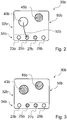
- FIG. 2 shows an indication unit 30b of a hob with variable cooking surface in a first display state.
- the indication unit 30b is formed by a touch-sensitive screen.
- the indication unit 30b has a first and a second display module 32b, 34b, which are each formed by different partial areas of the touch-sensitive screen.
- the first display module 32b is provided to display an image of the variable cooking surface.
- the second display module 34b is provided to represent symbolic images 23b, 25b, 27b, 29b of four rotary controls of a control unit of the cooktop device.
- the second display module 34b is formed by a strip at a lower edge of the screen of the touch-sensitive screen.
- An associating unit 50b of the cooktop apparatus is provided, in response to an operator input 52b, a swipe movement from a cooking zone associated display area 43b to an image 25b of a selected rotary control, to associate the cooking zone with the control knob of the control unit selected by the operator ( FIG. 3 ).
- the indication unit 30b is intended to display associated cooking zones representing display areas 43b, 45b and images representative of knobs 23b, 25b, 27b, 29b in the same color.
- representations representing rotary control are abstracted.
- the second display module is divided into equal partial areas, each representing one of the rotary control.
- FIG. 4 shows an indication unit 30c of another hob with a variable cooking surface.
- the indication unit 30c has a screen which is provided to display an image of the variable cooking surface of the cooktop apparatus in at least one display mode.
- the indication unit 30c is provided to display symbols representing an associated knob in display areas 43c, 45c that represent cooking zones.
- the indication unit 30c is to provided on each display area 43c, 45c represent an image 25c, 29c of a control unit with four rotary controls, wherein an image of a the display area 43c, 45c and its associated cooking zone associated knob is highlighted respectively. Alternatively, it is conceivable that numerals are displayed.
- FIG. 5 shows an operating unit 20d of a hob with variable cooking surface.
- the operating unit 20d has a rotary knob 22d in the form of a virtual rotary knob.
- the operating unit 20d is formed by a touch-sensitive screen.
- a control unit is provided to represent an image of the variable cooking surface and cooking zones formed.
- the control unit is designed to convert the display area into an image of the rotary knob 22d when a display area 43d representing a cooking zone is touched.
- the control unit is arranged to change a heating power of an associated cooking zone when an operator input 52d, a guided contact along an edge of the rotary knob 22d shown, is detected.
- the control unit is provided to rotate a representation of the rotary knob 22d corresponding to the set heating power and the movement along the edge.
- a rotary contact can be performed by a turning center is determined with a static finger and a rotational movement is performed by means of a second finger relative to the first finger ,
- FIG. 6 shows a hob 10e with a hob device 12e.
- Hob device 12e has a variable cooking surface 14e and a control unit 18e.
- the cooktop device 12e has an operating unit 20e, which has a single rotary knob 22e.
- the rotary control 22e is designed as a free rotary control.
- the hob device 12e has an allocation unit 50e.
- the allocation unit 50e has a single rotary knob 54e.
- the rotary knob 54e is a free rotary knob educated.
- the allocation unit 50e is intended to select a cooking zone whose heating power is to be variable. By means of a rotation of the rotary knob 54e of the allocation unit 50e, the cooking zones are activated one after the other individually.
- Hob device 12e has an indication unit 30e designed to highlight a selected cooking zone.
- the indication unit 30e has a screen.
- the indication unit 30e, the allocation unit 50e and the operation unit 20e are arranged together in a separate bar.
- an allocation unit has a touch-sensitive screen instead of a rotary control, wherein an operator activates a cooking zone by selection on the touch-sensitive screen and then controls it by means of the rotary control of the operating unit.
Landscapes
- Physics & Mathematics (AREA)
- Electromagnetism (AREA)
- Electric Ovens (AREA)
- Electric Stoves And Ranges (AREA)
Claims (8)
- Dispositif de plan de cuisson comprenant au moins une surface de cuisson (14) variable, comprenant au moins une unité de manipulation (20) et comprenant au moins une unité de commande (18) qui est ménagée pour commander la surface de cuisson (14) variable en fonction d'entrées réalisées par l'intermédiaire de l'unité de manipulation (20), l'unité de manipulation (20) présentant au moins un bouton rotatif (22, 24, 26, 28) et l'unité de commande (18) étant ménagée pour modifier au moins une puissance de chauffage d'au moins une zone de cuisson (42, 44) de la surface de cuisson (14) variable en fonction d'entrées réalisées par l'intermédiaire du bouton rotatif (22, 24, 26, 28), caractérisé par au moins une unité d'attribution (50) qui est ménagée pour réaliser une attribution entre au moins l'un bouton rotatif (22, 24, 26, 28) et au moins une zone de cuisson (42, 44) en fonction d'entrées d'utilisateur (52), le bouton rotatif (22, 24, 26, 28) étant réalisé come bouton rotatif virtuel.
- Dispositif de plan de cuisson selon la revendication 1, caractérisé par au moins une unité d'indication (30) qui est ménagée pour indiquer une attribution de l'au moins un bouton rotatif (22, 24, 26, 28) à l'au moins une zone de cuisson (42, 44).
- Dispositif de plan de cuisson selon la revendication 2, caractérisé en ce que l'unité d'indication (30) présente au moins un écran.
- Dispositif de plan de cuisson selon l'une quelconque des revendications précédentes, caractérisé en ce que l'unité d'attribution (50) présente au moins un bouton rotatif (54).
- Dispositif de plan de cuisson selon l'une quelconque des revendications précédentes, caractérisé en ce que l'unité de manipulation (20) présente au moins deux boutons rotatifs (22, 24, 26, 28) et en ce que l'unité d'attribution (50) est ménagée pour attribuer un bouton rotatif (22, 24, 26, 28) de l'unité de manipulation (20), sélectionné par un utilisateur, au moins à une zone de cuisson (42, 44).
- Dispositif de plan de cuisson selon l'une quelconque des revendications précédentes, caractérisé en ce qu'au moins un bouton rotatif (22, 24, 26, 28) de l'unité de manipulation (20) est réalisé comme bouton rotatif mécanique.
- Plan de cuisson comprenant un dispositif de plan de cuisson (12) selon l'une quelconque des revendications précédentes.
- Procédé de fonctionnement d'un dispositif de plan de cuisson (12), comprenant au moins une surface de cuisson (14) variable, comprenant au moins une unité de manipulation (20) et comprenant au moins une unité de commande (18) à l'aide de laquelle la surface de cuisson (14) variable est commandée en fonction d'entrées réalisées par l'intermédiaire de l'unité de manipulation (20), l'unité de manipulation (20) présentant au moins un bouton rotatif (22, 24, 26, 28), et au moins une puissance de chauffage d'au moins une zone de cuisson (42, 44) de la surface de cuisson (14) variable étant modifiée au moyen de l'unité de commande (18) en fonction d'entrées réalisées par l'intermédiaire du bouton rotatif (22, 24, 26, 28), et comprenant au moins une unité d'attribution (50) à l'aide de laquelle une attribution entre au moins l'un bouton rotatif (22, 24, 26, 28) et au moins une zone de cuisson (42, 44) est exécutée en fonction d'entrées d'utilisateur (52), le bouton rotatif (22, 24, 26, 28) étant réalisé come bouton rotatif virtuel.
Applications Claiming Priority (1)
| Application Number | Priority Date | Filing Date | Title |
|---|---|---|---|
| ES201231416 | 2012-09-13 |
Publications (2)
| Publication Number | Publication Date |
|---|---|
| EP2709423A1 EP2709423A1 (fr) | 2014-03-19 |
| EP2709423B1 true EP2709423B1 (fr) | 2017-05-10 |
Family
ID=49118343
Family Applications (1)
| Application Number | Title | Priority Date | Filing Date |
|---|---|---|---|
| EP13182904.6A Active EP2709423B1 (fr) | 2012-09-13 | 2013-09-04 | Dispositif de champ de cuisson |
Country Status (2)
| Country | Link |
|---|---|
| EP (1) | EP2709423B1 (fr) |
| ES (1) | ES2633887T3 (fr) |
Families Citing this family (5)
| Publication number | Priority date | Publication date | Assignee | Title |
|---|---|---|---|---|
| DE102014207261B4 (de) * | 2014-04-15 | 2016-02-18 | E.G.O. Elektro-Gerätebau GmbH | Kochfeld und Verfahren zum Betrieb eines Kochfelds |
| ES2590427B1 (es) | 2015-05-21 | 2017-09-07 | Bsh Electrodomésticos España, S.A. | Sistema de cocción |
| KR102407943B1 (ko) * | 2017-12-22 | 2022-06-13 | 삼성전자 주식회사 | 유도 가열 조리기 및 그 표시 제어방법 |
| KR102570605B1 (ko) | 2018-07-13 | 2023-08-23 | 엘지전자 주식회사 | 유도 가열 조리기기 |
| DE102018131031A1 (de) * | 2018-12-05 | 2020-06-10 | Miele & Cie. Kg | Vorrichtung und Verfahren zum Zuordnen eines Assistenzprogramms zu einer Kochstelle und Haushaltsgerät |
Citations (2)
| Publication number | Priority date | Publication date | Assignee | Title |
|---|---|---|---|---|
| DE102008032449A1 (de) * | 2008-07-10 | 2010-01-14 | Rational Ag | Anzeigeverfahren und Gargerät hierfür |
| US20120003364A1 (en) * | 2009-01-27 | 2012-01-05 | Rational Ag | Method for selecting and arranging program representatives and a cooking device therefor |
Family Cites Families (5)
| Publication number | Priority date | Publication date | Assignee | Title |
|---|---|---|---|---|
| US3215817A (en) * | 1963-05-22 | 1965-11-02 | Duncan C Peek | Heating devices for utensils |
| ES2115525B1 (es) * | 1996-03-20 | 1999-02-16 | Lato Ventura Vale | Sistema de aprovechamiento de la superficie total de vitroceramica para cocina. |
| JP4854596B2 (ja) * | 2007-05-28 | 2012-01-18 | 三菱電機株式会社 | 誘導加熱調理器 |
| JP4863961B2 (ja) * | 2007-10-15 | 2012-01-25 | 三菱電機株式会社 | 誘導加熱調理器 |
| WO2012111244A1 (fr) * | 2011-02-14 | 2012-08-23 | 三菱電機株式会社 | Cuisinière à chauffage par induction |
-
2013
- 2013-09-04 ES ES13182904.6T patent/ES2633887T3/es active Active
- 2013-09-04 EP EP13182904.6A patent/EP2709423B1/fr active Active
Patent Citations (2)
| Publication number | Priority date | Publication date | Assignee | Title |
|---|---|---|---|---|
| DE102008032449A1 (de) * | 2008-07-10 | 2010-01-14 | Rational Ag | Anzeigeverfahren und Gargerät hierfür |
| US20120003364A1 (en) * | 2009-01-27 | 2012-01-05 | Rational Ag | Method for selecting and arranging program representatives and a cooking device therefor |
Also Published As
| Publication number | Publication date |
|---|---|
| EP2709423A1 (fr) | 2014-03-19 |
| ES2633887T3 (es) | 2017-09-25 |
Similar Documents
| Publication | Publication Date | Title |
|---|---|---|
| EP2709423B1 (fr) | Dispositif de champ de cuisson | |
| EP2884187B1 (fr) | Procédé d'aide à l'utilisateur, composant d'écran et fabrication d'un composant d'écran | |
| DE112008002807B4 (de) | Kochfeld und Verfahren zum Betreiben eines Kochfelds | |
| DE102008064731B4 (de) | Kochfeld mit einem bewegbaren Heizelement | |
| EP2370734A2 (fr) | Table de cuisson pourvue d'un écran et procédé pour faire fonctionner une table de cuisson | |
| EP2986917B1 (fr) | Table de cuisson comprenant une zone de cuisson et un symbole réduit dans la zone de cuisson dans une unité d'affichage, ainsi que procédé servant à faire fonctionner une table de cuisson | |
| EP2527747B1 (fr) | Dispositif de commande d'un champ de cuisson | |
| DE102008032453A1 (de) | Anzeigeverfahren und Gargerät hierfür | |
| EP2065650B1 (fr) | Appareil ménager doté d'une interface utilisateur comprenant un élément de réglage | |
| EP2258987A2 (fr) | Appareil ménager doté d'un écran tactile | |
| EP2703728B2 (fr) | Dispositif de plate de cuisson | |
| DE102011102394B4 (de) | Vorrichtung und Verfahren zur Bedienung eines Kochfeldes | |
| DE102008032450B4 (de) | Anzeigeverfahren und Gargerät hierfür | |
| DE102008032449B4 (de) | Verfahren zum Verändern wenigstens einer Anzeige eines Bedienmenüs eines Gargeräts | |
| EP1158838B1 (fr) | Dispositif de commutation commandé par effleurement | |
| DE102008032451B4 (de) | Anzeigeverfahren und Gargerät hierfür | |
| EP1344983A2 (fr) | Arrangement pour le contrôle d'un plaque de cuisson | |
| EP2840867A1 (fr) | Dispositif de plaque de cuisson | |
| EP2709422B1 (fr) | Dispositif de champ de cuisson | |
| EP2826336B1 (fr) | Dispositif de plaque de cuisson | |
| EP2603739B1 (fr) | Appareil électroménager présentant une plaque de cuisson et procédé d'affichage de la consommation d'énergie | |
| DE102008032452A1 (de) | Anzeigeverfahren und Gargerät hierfür | |
| EP2767761B1 (fr) | Gamme d'appareils ménagers et procédé de fabrication d'appareils ménagers à commandes différentes | |
| EP1485786A2 (fr) | Ecran tactile | |
| EP2708818B1 (fr) | Dispositif de plaque au cuisson |
Legal Events
| Date | Code | Title | Description |
|---|---|---|---|
| PUAI | Public reference made under article 153(3) epc to a published international application that has entered the european phase |
Free format text: ORIGINAL CODE: 0009012 |
|
| AK | Designated contracting states |
Kind code of ref document: A1 Designated state(s): AL AT BE BG CH CY CZ DE DK EE ES FI FR GB GR HR HU IE IS IT LI LT LU LV MC MK MT NL NO PL PT RO RS SE SI SK SM TR |
|
| AX | Request for extension of the european patent |
Extension state: BA ME |
|
| 17P | Request for examination filed |
Effective date: 20140919 |
|
| RBV | Designated contracting states (corrected) |
Designated state(s): AL AT BE BG CH CY CZ DE DK EE ES FI FR GB GR HR HU IE IS IT LI LT LU LV MC MK MT NL NO PL PT RO RS SE SI SK SM TR |
|
| RAP1 | Party data changed (applicant data changed or rights of an application transferred) |
Owner name: BSH HAUSGERAETE GMBH |
|
| 17Q | First examination report despatched |
Effective date: 20160617 |
|
| GRAP | Despatch of communication of intention to grant a patent |
Free format text: ORIGINAL CODE: EPIDOSNIGR1 |
|
| INTG | Intention to grant announced |
Effective date: 20161216 |
|
| GRAS | Grant fee paid |
Free format text: ORIGINAL CODE: EPIDOSNIGR3 |
|
| GRAA | (expected) grant |
Free format text: ORIGINAL CODE: 0009210 |
|
| AK | Designated contracting states |
Kind code of ref document: B1 Designated state(s): AL AT BE BG CH CY CZ DE DK EE ES FI FR GB GR HR HU IE IS IT LI LT LU LV MC MK MT NL NO PL PT RO RS SE SI SK SM TR |
|
| REG | Reference to a national code |
Ref country code: GB Ref legal event code: FG4D Free format text: NOT ENGLISH |
|
| REG | Reference to a national code |
Ref country code: AT Ref legal event code: REF Ref document number: 893545 Country of ref document: AT Kind code of ref document: T Effective date: 20170515 Ref country code: CH Ref legal event code: EP |
|
| REG | Reference to a national code |
Ref country code: IE Ref legal event code: FG4D Free format text: LANGUAGE OF EP DOCUMENT: GERMAN |
|
| REG | Reference to a national code |
Ref country code: DE Ref legal event code: R096 Ref document number: 502013007200 Country of ref document: DE |
|
| REG | Reference to a national code |
Ref country code: NL Ref legal event code: MP Effective date: 20170510 |
|
| REG | Reference to a national code |
Ref country code: ES Ref legal event code: FG2A Ref document number: 2633887 Country of ref document: ES Kind code of ref document: T3 Effective date: 20170925 Ref country code: LT Ref legal event code: MG4D Ref country code: FR Ref legal event code: PLFP Year of fee payment: 5 |
|
| PG25 | Lapsed in a contracting state [announced via postgrant information from national office to epo] |
Ref country code: NO Free format text: LAPSE BECAUSE OF FAILURE TO SUBMIT A TRANSLATION OF THE DESCRIPTION OR TO PAY THE FEE WITHIN THE PRESCRIBED TIME-LIMIT Effective date: 20170810 Ref country code: FI Free format text: LAPSE BECAUSE OF FAILURE TO SUBMIT A TRANSLATION OF THE DESCRIPTION OR TO PAY THE FEE WITHIN THE PRESCRIBED TIME-LIMIT Effective date: 20170510 Ref country code: GR Free format text: LAPSE BECAUSE OF FAILURE TO SUBMIT A TRANSLATION OF THE DESCRIPTION OR TO PAY THE FEE WITHIN THE PRESCRIBED TIME-LIMIT Effective date: 20170811 Ref country code: HR Free format text: LAPSE BECAUSE OF FAILURE TO SUBMIT A TRANSLATION OF THE DESCRIPTION OR TO PAY THE FEE WITHIN THE PRESCRIBED TIME-LIMIT Effective date: 20170510 Ref country code: LT Free format text: LAPSE BECAUSE OF FAILURE TO SUBMIT A TRANSLATION OF THE DESCRIPTION OR TO PAY THE FEE WITHIN THE PRESCRIBED TIME-LIMIT Effective date: 20170510 |
|
| PG25 | Lapsed in a contracting state [announced via postgrant information from national office to epo] |
Ref country code: PL Free format text: LAPSE BECAUSE OF FAILURE TO SUBMIT A TRANSLATION OF THE DESCRIPTION OR TO PAY THE FEE WITHIN THE PRESCRIBED TIME-LIMIT Effective date: 20170510 Ref country code: IS Free format text: LAPSE BECAUSE OF FAILURE TO SUBMIT A TRANSLATION OF THE DESCRIPTION OR TO PAY THE FEE WITHIN THE PRESCRIBED TIME-LIMIT Effective date: 20170910 Ref country code: SE Free format text: LAPSE BECAUSE OF FAILURE TO SUBMIT A TRANSLATION OF THE DESCRIPTION OR TO PAY THE FEE WITHIN THE PRESCRIBED TIME-LIMIT Effective date: 20170510 Ref country code: LV Free format text: LAPSE BECAUSE OF FAILURE TO SUBMIT A TRANSLATION OF THE DESCRIPTION OR TO PAY THE FEE WITHIN THE PRESCRIBED TIME-LIMIT Effective date: 20170510 Ref country code: NL Free format text: LAPSE BECAUSE OF FAILURE TO SUBMIT A TRANSLATION OF THE DESCRIPTION OR TO PAY THE FEE WITHIN THE PRESCRIBED TIME-LIMIT Effective date: 20170510 Ref country code: RS Free format text: LAPSE BECAUSE OF FAILURE TO SUBMIT A TRANSLATION OF THE DESCRIPTION OR TO PAY THE FEE WITHIN THE PRESCRIBED TIME-LIMIT Effective date: 20170510 Ref country code: BG Free format text: LAPSE BECAUSE OF FAILURE TO SUBMIT A TRANSLATION OF THE DESCRIPTION OR TO PAY THE FEE WITHIN THE PRESCRIBED TIME-LIMIT Effective date: 20170810 |
|
| PG25 | Lapsed in a contracting state [announced via postgrant information from national office to epo] |
Ref country code: CZ Free format text: LAPSE BECAUSE OF FAILURE TO SUBMIT A TRANSLATION OF THE DESCRIPTION OR TO PAY THE FEE WITHIN THE PRESCRIBED TIME-LIMIT Effective date: 20170510 Ref country code: EE Free format text: LAPSE BECAUSE OF FAILURE TO SUBMIT A TRANSLATION OF THE DESCRIPTION OR TO PAY THE FEE WITHIN THE PRESCRIBED TIME-LIMIT Effective date: 20170510 Ref country code: DK Free format text: LAPSE BECAUSE OF FAILURE TO SUBMIT A TRANSLATION OF THE DESCRIPTION OR TO PAY THE FEE WITHIN THE PRESCRIBED TIME-LIMIT Effective date: 20170510 Ref country code: RO Free format text: LAPSE BECAUSE OF FAILURE TO SUBMIT A TRANSLATION OF THE DESCRIPTION OR TO PAY THE FEE WITHIN THE PRESCRIBED TIME-LIMIT Effective date: 20170510 Ref country code: SK Free format text: LAPSE BECAUSE OF FAILURE TO SUBMIT A TRANSLATION OF THE DESCRIPTION OR TO PAY THE FEE WITHIN THE PRESCRIBED TIME-LIMIT Effective date: 20170510 |
|
| REG | Reference to a national code |
Ref country code: DE Ref legal event code: R097 Ref document number: 502013007200 Country of ref document: DE |
|
| PG25 | Lapsed in a contracting state [announced via postgrant information from national office to epo] |
Ref country code: SM Free format text: LAPSE BECAUSE OF FAILURE TO SUBMIT A TRANSLATION OF THE DESCRIPTION OR TO PAY THE FEE WITHIN THE PRESCRIBED TIME-LIMIT Effective date: 20170510 |
|
| PLBE | No opposition filed within time limit |
Free format text: ORIGINAL CODE: 0009261 |
|
| STAA | Information on the status of an ep patent application or granted ep patent |
Free format text: STATUS: NO OPPOSITION FILED WITHIN TIME LIMIT |
|
| 26N | No opposition filed |
Effective date: 20180213 |
|
| REG | Reference to a national code |
Ref country code: CH Ref legal event code: PL |
|
| PG25 | Lapsed in a contracting state [announced via postgrant information from national office to epo] |
Ref country code: MC Free format text: LAPSE BECAUSE OF FAILURE TO SUBMIT A TRANSLATION OF THE DESCRIPTION OR TO PAY THE FEE WITHIN THE PRESCRIBED TIME-LIMIT Effective date: 20170510 Ref country code: SI Free format text: LAPSE BECAUSE OF FAILURE TO SUBMIT A TRANSLATION OF THE DESCRIPTION OR TO PAY THE FEE WITHIN THE PRESCRIBED TIME-LIMIT Effective date: 20170510 |
|
| REG | Reference to a national code |
Ref country code: IE Ref legal event code: MM4A |
|
| REG | Reference to a national code |
Ref country code: BE Ref legal event code: MM Effective date: 20170930 |
|
| PG25 | Lapsed in a contracting state [announced via postgrant information from national office to epo] |
Ref country code: LU Free format text: LAPSE BECAUSE OF NON-PAYMENT OF DUE FEES Effective date: 20170904 |
|
| PG25 | Lapsed in a contracting state [announced via postgrant information from national office to epo] |
Ref country code: CH Free format text: LAPSE BECAUSE OF NON-PAYMENT OF DUE FEES Effective date: 20170930 Ref country code: IE Free format text: LAPSE BECAUSE OF NON-PAYMENT OF DUE FEES Effective date: 20170904 Ref country code: LI Free format text: LAPSE BECAUSE OF NON-PAYMENT OF DUE FEES Effective date: 20170930 |
|
| PG25 | Lapsed in a contracting state [announced via postgrant information from national office to epo] |
Ref country code: BE Free format text: LAPSE BECAUSE OF NON-PAYMENT OF DUE FEES Effective date: 20170930 |
|
| REG | Reference to a national code |
Ref country code: FR Ref legal event code: PLFP Year of fee payment: 6 |
|
| PG25 | Lapsed in a contracting state [announced via postgrant information from national office to epo] |
Ref country code: MT Free format text: LAPSE BECAUSE OF FAILURE TO SUBMIT A TRANSLATION OF THE DESCRIPTION OR TO PAY THE FEE WITHIN THE PRESCRIBED TIME-LIMIT Effective date: 20170510 |
|
| PG25 | Lapsed in a contracting state [announced via postgrant information from national office to epo] |
Ref country code: HU Free format text: LAPSE BECAUSE OF FAILURE TO SUBMIT A TRANSLATION OF THE DESCRIPTION OR TO PAY THE FEE WITHIN THE PRESCRIBED TIME-LIMIT; INVALID AB INITIO Effective date: 20130904 |
|
| PG25 | Lapsed in a contracting state [announced via postgrant information from national office to epo] |
Ref country code: CY Free format text: LAPSE BECAUSE OF NON-PAYMENT OF DUE FEES Effective date: 20170510 |
|
| REG | Reference to a national code |
Ref country code: AT Ref legal event code: MM01 Ref document number: 893545 Country of ref document: AT Kind code of ref document: T Effective date: 20180904 |
|
| PG25 | Lapsed in a contracting state [announced via postgrant information from national office to epo] |
Ref country code: MK Free format text: LAPSE BECAUSE OF FAILURE TO SUBMIT A TRANSLATION OF THE DESCRIPTION OR TO PAY THE FEE WITHIN THE PRESCRIBED TIME-LIMIT Effective date: 20170510 |
|
| PG25 | Lapsed in a contracting state [announced via postgrant information from national office to epo] |
Ref country code: AT Free format text: LAPSE BECAUSE OF NON-PAYMENT OF DUE FEES Effective date: 20180904 |
|
| PG25 | Lapsed in a contracting state [announced via postgrant information from national office to epo] |
Ref country code: TR Free format text: LAPSE BECAUSE OF FAILURE TO SUBMIT A TRANSLATION OF THE DESCRIPTION OR TO PAY THE FEE WITHIN THE PRESCRIBED TIME-LIMIT Effective date: 20170510 |
|
| PG25 | Lapsed in a contracting state [announced via postgrant information from national office to epo] |
Ref country code: PT Free format text: LAPSE BECAUSE OF FAILURE TO SUBMIT A TRANSLATION OF THE DESCRIPTION OR TO PAY THE FEE WITHIN THE PRESCRIBED TIME-LIMIT Effective date: 20170510 |
|
| PG25 | Lapsed in a contracting state [announced via postgrant information from national office to epo] |
Ref country code: AL Free format text: LAPSE BECAUSE OF FAILURE TO SUBMIT A TRANSLATION OF THE DESCRIPTION OR TO PAY THE FEE WITHIN THE PRESCRIBED TIME-LIMIT Effective date: 20170510 |
|
| PGFP | Annual fee paid to national office [announced via postgrant information from national office to epo] |
Ref country code: GB Payment date: 20230921 Year of fee payment: 11 |
|
| PGFP | Annual fee paid to national office [announced via postgrant information from national office to epo] |
Ref country code: FR Payment date: 20230919 Year of fee payment: 11 Ref country code: DE Payment date: 20230930 Year of fee payment: 11 |
|
| PGFP | Annual fee paid to national office [announced via postgrant information from national office to epo] |
Ref country code: ES Payment date: 20231019 Year of fee payment: 11 |
|
| PGFP | Annual fee paid to national office [announced via postgrant information from national office to epo] |
Ref country code: IT Payment date: 20230929 Year of fee payment: 11 |