EP2709216A2 - Verbinder - Google Patents
Verbinder Download PDFInfo
- Publication number
- EP2709216A2 EP2709216A2 EP13183719.7A EP13183719A EP2709216A2 EP 2709216 A2 EP2709216 A2 EP 2709216A2 EP 13183719 A EP13183719 A EP 13183719A EP 2709216 A2 EP2709216 A2 EP 2709216A2
- Authority
- EP
- European Patent Office
- Prior art keywords
- connector
- lock
- state
- mating connector
- view
- Prior art date
- Legal status (The legal status is an assumption and is not a legal conclusion. Google has not performed a legal analysis and makes no representation as to the accuracy of the status listed.)
- Granted
Links
Images











Classifications
-
- H—ELECTRICITY
- H01—ELECTRIC ELEMENTS
- H01R—ELECTRICALLY-CONDUCTIVE CONNECTIONS; STRUCTURAL ASSOCIATIONS OF A PLURALITY OF MUTUALLY-INSULATED ELECTRICAL CONNECTING ELEMENTS; COUPLING DEVICES; CURRENT COLLECTORS
- H01R13/00—Details of coupling devices of the kinds covered by groups H01R12/70 or H01R24/00 - H01R33/00
- H01R13/62—Means for facilitating engagement or disengagement of coupling parts or for holding them in engagement
- H01R13/639—Additional means for holding or locking coupling parts together, after engagement, e.g. separate keylock, retainer strap
-
- H—ELECTRICITY
- H01—ELECTRIC ELEMENTS
- H01R—ELECTRICALLY-CONDUCTIVE CONNECTIONS; STRUCTURAL ASSOCIATIONS OF A PLURALITY OF MUTUALLY-INSULATED ELECTRICAL CONNECTING ELEMENTS; COUPLING DEVICES; CURRENT COLLECTORS
- H01R13/00—Details of coupling devices of the kinds covered by groups H01R12/70 or H01R24/00 - H01R33/00
- H01R13/62—Means for facilitating engagement or disengagement of coupling parts or for holding them in engagement
-
- H—ELECTRICITY
- H01—ELECTRIC ELEMENTS
- H01R—ELECTRICALLY-CONDUCTIVE CONNECTIONS; STRUCTURAL ASSOCIATIONS OF A PLURALITY OF MUTUALLY-INSULATED ELECTRICAL CONNECTING ELEMENTS; COUPLING DEVICES; CURRENT COLLECTORS
- H01R13/00—Details of coupling devices of the kinds covered by groups H01R12/70 or H01R24/00 - H01R33/00
- H01R13/62—Means for facilitating engagement or disengagement of coupling parts or for holding them in engagement
- H01R13/627—Snap or like fastening
- H01R13/6271—Latching means integral with the housing
- H01R13/6273—Latching means integral with the housing comprising two latching arms
-
- H—ELECTRICITY
- H01—ELECTRIC ELEMENTS
- H01R—ELECTRICALLY-CONDUCTIVE CONNECTIONS; STRUCTURAL ASSOCIATIONS OF A PLURALITY OF MUTUALLY-INSULATED ELECTRICAL CONNECTING ELEMENTS; COUPLING DEVICES; CURRENT COLLECTORS
- H01R13/00—Details of coupling devices of the kinds covered by groups H01R12/70 or H01R24/00 - H01R33/00
- H01R13/62—Means for facilitating engagement or disengagement of coupling parts or for holding them in engagement
- H01R13/627—Snap or like fastening
- H01R13/6275—Latching arms not integral with the housing
-
- H—ELECTRICITY
- H01—ELECTRIC ELEMENTS
- H01R—ELECTRICALLY-CONDUCTIVE CONNECTIONS; STRUCTURAL ASSOCIATIONS OF A PLURALITY OF MUTUALLY-INSULATED ELECTRICAL CONNECTING ELEMENTS; COUPLING DEVICES; CURRENT COLLECTORS
- H01R13/00—Details of coupling devices of the kinds covered by groups H01R12/70 or H01R24/00 - H01R33/00
- H01R13/62—Means for facilitating engagement or disengagement of coupling parts or for holding them in engagement
- H01R13/629—Additional means for facilitating engagement or disengagement of coupling parts, e.g. aligning or guiding means, levers, gas pressure electrical locking indicators, manufacturing tolerances
- H01R13/633—Additional means for facilitating engagement or disengagement of coupling parts, e.g. aligning or guiding means, levers, gas pressure electrical locking indicators, manufacturing tolerances for disengagement only
Definitions
- the present invention relates to a connector to be connected to a mating connector to serve for transferring a signal or electric power.
- a connector including a lock mechanism to lock to a mating connector to prevent disengagement from the mating connector.
- JP H09-63694A illustrates a connector which includes a lock piece to lock to a mating connector and a slide plate to release locking to the mating connector by the lock piece.
- the connector illustrated in JP H09-63694A has a configuration in which the lock piece interferes with the mating connector to be deformed when being mated with the mating connector, the interference between the lock piece and the mating connector is added as an insertion resistance when being engaged.
- a connector including many contacts or a connector to transfer high electrical current has a large basic insertion resistance itself excluding an insertion resistance to be added by a lock member. For this reason, when the insertion resistance is further added by the lock member, the insertion resistance becomes so large that a problem for handling the connector may arise.
- the present invention has been made to provide a connector including a lock mechanism in which an insertion resistance when being engaged is reduced or in which an insertion resistance is reduced when the connector is engaged.
- a connector according to one aspect of the present invention includes:
- the connector Since the connector according to the present invention includes the above-described slide member, the connector is engaged with the mating connector in a state in which the slide member is locked at the second position, so that the connector is engaged while being in a state in which the lock section does not interfere with the mating connector.
- the lock section is provided on each of two surfaces of the housing which two surfaces face in directions opposite to each other, and the slide member is provided on each of the two surfaces, and the slide members each provided on each of the two surfaces slide independently from each other and act independently from each other on the lock sections each provided on each of the two surfaces.
- a connector such as one serving for transferring high electrical current is required to be tightly locked enough not to be easily disengaged from a mating connector, and for this reason, a slide operation of a slide member is required to be performed by a large force.
- the configuration in which the lock section is provided on each of the above-described two surfaces and the slide member is also provided on each of those two surfaces is applied, so that it becomes easy to perform operations of locking and lock-releasing.
- an insertion resistance when being engaged is reduced or an insertion resistance is reduced when the connector is engaged.
- a connector includes a slide member, the slide member being slidable to a housing, is slid in a direction to be locked to the housing at a first position as slid in the direction, and is slid in a direction to be locked to the housing at a second position as slid in the direction, the slide member holding a lock section in a state of being locked to a mating connector at the first position, and holding the lock section in a state of being released from locked to the mating connector in the second position.
- FIG. 1 and FIG. 2 are perspective views illustrating a state in which a connector as an embodiment of the present invention is engaged with a mating connector, viewed from points different from each other.
- FIG. 2 In these figures are illustrated a state in which three mating connectors 200 are screwed to a support plate 300 formed with an opening 301 for engagement (see FIG. 2 ), and three connectors 100 according to the present embodiment are engaged with those three mating connectors 200, on or one by one, or are engaged with those three respective mating connectors 200.
- the connectors 100 according to the present embodiment and the mating connectors 200 are connectors to transfer high electrical current, for example, of the order 300A, via cables 101, 201.
- the connector 100 includes slide members 120 which slide with respect to a housing 110 in a P-R direction illustrated in the figures on both side surfaces opposite to each other.
- the connector 100 and the mating connector 200 are locked to each other for preventing disengagement, and the slide members 120 are slid in the direction indicated by the arrow R, the locking is released so that the connector 100 can be pulled out from the mating connector 200.
- FIG. 3 is an exploded perspective view of the connector of the present embodiment and the mating connector.
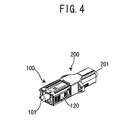
- FIG. 4 is a perspective view illustrating a state in which the connector of the present embodiment and the mating connector are assembled respectively and engaged with each other.
- the connector 100 includes a contact 130 and a leaf spring 140 in addition to the housing 110 and the slide members 120 illustrated also in FIGS. 1 and 2 .
- a core wire 101a of a cable 101 is to be connected to the contact 130.
- the mating connector 200 includes a contact 230 and a leaf spring 240 in addition to the housing 210.
- a core wire 201a of a cable 201 is to be connected to the contact 230.
- Lock sections 111 each having a cantilever shape are provided on both side surfaces of the housing 110, respectively. These lock sections 111 serves for locking to the housing 210 of the mating connector 200 to lock to the mating connector 200 for preventing disengagement.
- the slide members 120 are provided on both of the side surfaces of the housing 110, respectively, and are slid independently from each other along guide walls 112 of the side surfaces of the housing 110.
- slide members 120 When the slide members 120 are slid in the direction indicated by the arrow P, the slide members 120 are locked by a locking piece 111a (see FIG. 10 ) to the mating connector 200, and when the slide members 120 are slid in the direction indicated by the arrow R, the locking to the mating connector 200 is released.
- These slide members 120 are configured such that the slide members 120 are locked at both a first position where the slide members 120 are slid in the direction indicated by the arrow P and a second position where the slide members 120 are slid in the direction indicated by the arrow R, and a force is applied to release the locking so that the slide members are slid. Details will be described later.
- the leaf spring 140 abuts on a rear surface 131 opposite to a surface of the contact 130 which surface makes contact with the contact 230 of the mating connector 200, and the leaf spring 140 serves for pressing the contact 130 against the contact 230 of the mating connector 200 when the connector 100 is engaged with the mating connector 200.
- the core wire 201a of the cable 201 is connected to the contact 230, and the leaf spring 240 serves for pressing the contact 230 against the contact 130.
- the housing 210 of the mating connector 200 includes a configuration in which the housing 210 locks to the lock section 111 inside a mating opening 211 thereof.
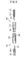
- FIG. 5 is a plan view of the connector of the present embodiment and the mating connector in a state of disengagement. However, FIG. 5 illustrates the contacts 130, 230 in a state of being connected to the cables 110, 210 are removed or being positioned outside the housing 110, 210.
- FIG. 6 is a sectional view taken along the line A-A illustrated in FIG. 5 .
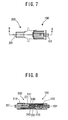
- FIG. 7 is a plan view of the connector of the present embodiment and the mating connector in the state of engagement.
- FIG. 8 is a sectional view taken along the line B-B illustrated in FIG. 7 .
- the contacts 130, 230 are arranged in a state in which the leaf springs 140, 240 abut on rear surfaces 131, 231 opposite to surfaces making contact with the contacts of the counterpart inside the housings 110, 210.
- the contacts 130, 230 are pressed by the respective counterpart contacts 230, 130, and their attitudes are changed to be oriented in directions to cause the leaf springs 140, 240 being abutted on to be elastically deformed.
- the contacts 130, 230 are pressed by the respective counterpart leaf springs 140, 240 to make contact with the contacts 230, 130 of the respective counterpart in predetermined strength, and in addition, maintains making contact with each other by the elasticity of the leaf springs even if receiving vibrations.
- FIG. 9 is a plan view of the connector of the present embodiment and the mating connector in the state of disengagement.
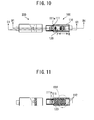
- FIG. 10 is a side view of the connector of the present embodiment and the mating connector in the state of disengagement.
- FIG. 11 is a sectional view taken along the line C1-C1 illustrated in FIG. 9 .
- FIG. 12 is a sectional view taken along the line D1-D1 illustrated in FIG. 10 .
- FIG. 13 is a sectional view taken along the line E1-E1 illustrated in FIG. 10 .
- FIG. 14 is an enlarged view of a portion indicated by the circle R14 illustrated in FIG. 11 .
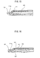
- FIG. 15 is an enlarged view of a portion indicated by the circle R15 illustrated in FIG. 12 .
- FIG. 16 is an enlarged view of a portion indicated by the circle R16 illustrated in FIG. 13 .
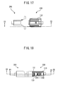
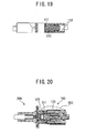
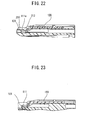
- FIGS. 17-23 are views respectively corresponding to the ones of FIGS. 9-16 excluding FIG. 14 .
- FIGS. 17 and 18 are a plan view and a side view of the connector of the present embodiment and the mating connector in the state of engagement, respectively.
- FIG. 19 is a sectional view taken along the line C2-C2 illustrated in FIG. 17 .
- FIG. 20 is a sectional view taken along the line D2-D2 illustrated in FIG. 18 .
- FIG. 21 is a sectional view taken along the line E2-E2 illustrated in FIG. 18 .
- FIG. 22 is an enlarged view of a portion indicated by the circle R22 illustrated in FIG. 20 .
- FIG. 23 is an enlarged view of a portion indicated by the circle R23 illustrated in FIG. 21 . Since a view in the state of engagement corresponding to FIG. 14 of the FIGS. 9-16 is same as the view of FIG. 14 representing the state of disengagement, overlapped descriptions are omitted here to eliminate redundancy.
- FIGS. 9-16 and FIGS. 17-23 each are views illustrating the state of being locked although there are differences between the state of engagement and the state of disengagement.
- the lock sections 111 each having the cantilever shape are provided on the both side surfaces of the housing 110 of the connector 100, respectively.
- a lock claw 111a to lock to the mating connector 200 is provided at a tip of each of the lock sections 111.
- each of the slides members 120 is provided on each of the both side surfaces of the housing 110 of the connector 100.
- the slide members 120 are slid in the direction indicated by the arrow P-R illustrated in FIG. 10 , and are slid while being sandwiched to be guided by the guide walls 112 provided on the both side surfaces of the housing 110 of the connector 100 (see FIG. 11 , FIG. 14 ).
- lock projection sections 122 are provided on the slide member 120 to project toward the guide walls 112.
- each of two lock depression sections 112a and each of two lock depression sections 112b are provided on each of the pair of guide walls 112 sandwiching the slide member 120.
- FIGS. 9-23 being described here illustrate a state in which the slide member 120 is locked to the lock depressions sections 112a positioned forward in the direction indicated by the arrow P.
- the slide member 120 is in the state in which the lock projection sections 122 are locked to the lock depression sections 112a, the tip section 121 of the slide member 120 is positioned under the tip of the lock section 111 to become a state of lifting up the lock claw 111a provided at the tip of the lock section 111 (see FIGS. 15-16 , FIGS. 22-23 ).
- the lock claw 111a locks, in the state of being lifted up, to the lock section 212 (see FIG. 22 ) provided on an inner wall surface of the mating opening 211 (see FIG. 3 ) of the mating connector 200, and is in a state of preventing the connector 100 form unintentionally being pulled out from the mating connector 200.
- FIGS. 24-31 are views respectively corresponding to FIGS. 9-16 , illustrating a lock-released state and the disengagement state.
- FIGS. 24, 25 are a plan view and a side view of the connector of the present embodiment and the mating connector.
- FIG. 26 is a sectional view taken along the line C3-C3 illustrated in FIG. 24 .
- FIG. 27 is a sectional view taken along the line D3-D3 illustrated in FIG. 25 .
- FIG. 28 a sectional view taken along the line E3-E3 illustrated in FIG. 25 .
- FIG. 29 is an enlarged view of a portion indicated by the circle R29 illustrated in FIG. 26 .
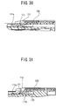
- FIG. 30 is an enlarged view of a portion indicated by the circle R30 illustrated in FIG. 27 .
- FIG. 31 is an enlarged view of a portion indicated by the circle R31 illustrated in FIG. 28 .
- FIGS. 32-38 are views respectively corresponding to FIGS. 24-31 excluding FIG. 29 in the state of engagement. Specifically, descriptions are as follows.
- FIGS. 32, 33 are a plan view and a side view of the connector and the mating connector in the present embodiment in the state of disengagement and the state of lock-released.
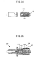
- FIG. 34 is a sectional view taken along the line C4-C4 illustrated in FIG. 32 .
- FIG. 35 is a sectional view taken along the line D4-D4 illustrated in FIG. 33 .
- FIG. 36 is a sectional view taken along the line E4-E4 illustrated in FIG. 33 .
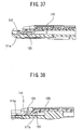
- FIG. 37 is an enlarged view of a portion indicated by the circle R37 illustrated in FIG. 37.
- FIG. 37 is an enlarged view of a portion indicated by the circle R37 illustrated in FIG. 37.
- FIG. 38 is an enlarged view of a portion indicated by the circle R38 illustrated in FIG. 36 . Since a view in the state of engagement corresponding to FIG. 29 of FIGS. 24-31 is same as the view of FIG. 29 representing the state of disengagement, overlapped descriptions are omitted here to eliminate redundancy.
- FIGS. 24-31 and FIGS. 32-38 each are views illustrating the state of lock-released although there are differences between the state of engagement and the state of disengagement.
- the tip section 121 of the slide member 120 is positioned lower than the tip section of the lock section 111, and being lifted up of the lock claw 111a provided at the tip section of the lock section 111 is released (see FIGS. 30-31 , FIGS. 37-38 ).
- lock section 111 when the slide member 120 is slid in the direction indicated by the arrow R illustrated in FIG. 10 , being lifted up of the lock claw 111a is released. Further in the lock section 111, when an extension section 111b on a side thereof engages in a cam manner with the projection section 123 (see FIG. 38 ) of the slide member 120, the lock claw 111a at the tip section of the lock section 111 is forcibly pressed up in a direction away from the lock section 212 (see FIG. 37 ) of the mating connector.
- the lock claw 111a of the lock section 111 is forcibly retracted to a position in which the lock claw 111a does not interfere with the housing 210 of the mating connector 200. Accordingly, the connector 100 is engaged with the mating connector 200 in the state in which the lock projections 122 of the slide section 120 are locked to the lock depression section 112b on the side of lock-released, the lock section 111 does not contribute to an insertion resistance, and thus, the engagement is performed by a smaller force correspondingly.
- the slide members 120 are slid up to the lock position where the lock projection sections 122 are locked to the lock depression sections 112a on the locked side, so that the connector 100 and the mating connector 200 is in the locked state in which they are secured to be prevented from being pulled out from each other.
- the lock claw 111a of the lock section 111 bumps against a portion other than the lock section 212 of the housing 210. For this reason, the slide member 120 can not be slid up to the locked position. In other words, the slide member 120 is slid up to the lock position, so that a state of complete engagement is confirmed and a state of incomplete engagement is prevented.
- a connector for transferring high electrical current is exemplified.
- the present invention is widely applied to a connector for transferring a signal.
Landscapes
- Details Of Connecting Devices For Male And Female Coupling (AREA)
Applications Claiming Priority (1)
| Application Number | Priority Date | Filing Date | Title |
|---|---|---|---|
| JP2012203263A JP6156904B2 (ja) | 2012-09-14 | 2012-09-14 | コネクタ |
Publications (3)
| Publication Number | Publication Date |
|---|---|
| EP2709216A2 true EP2709216A2 (de) | 2014-03-19 |
| EP2709216A3 EP2709216A3 (de) | 2014-10-22 |
| EP2709216B1 EP2709216B1 (de) | 2018-03-07 |
Family
ID=49117773
Family Applications (1)
| Application Number | Title | Priority Date | Filing Date |
|---|---|---|---|
| EP13183719.7A Active EP2709216B1 (de) | 2012-09-14 | 2013-09-10 | Verbinder |
Country Status (5)
| Country | Link |
|---|---|
| US (1) | US9118142B2 (de) |
| EP (1) | EP2709216B1 (de) |
| JP (1) | JP6156904B2 (de) |
| KR (1) | KR102006791B1 (de) |
| CN (1) | CN103682814B (de) |
Families Citing this family (1)
| Publication number | Priority date | Publication date | Assignee | Title |
|---|---|---|---|---|
| US10168488B1 (en) * | 2017-08-30 | 2019-01-01 | Te Connectivity Corporation | Tool-less ferrule retainer |
Citations (1)
| Publication number | Priority date | Publication date | Assignee | Title |
|---|---|---|---|---|
| JPH0963694A (ja) | 1995-08-21 | 1997-03-07 | Honda Tsushin Kogyo Kk | ロック機構を有するコネクタ |
Family Cites Families (11)
| Publication number | Priority date | Publication date | Assignee | Title |
|---|---|---|---|---|
| US5436744A (en) * | 1993-09-03 | 1995-07-25 | Motorola Inc. | Flexible liquid crystal display with integrated driver circuit and display electrodes formed on opposite sides of folded substrate |
| JP3425690B2 (ja) * | 1999-12-21 | 2003-07-14 | 日本航空電子工業株式会社 | コネクタ |
| US6896538B2 (en) | 2002-10-31 | 2005-05-24 | Tyco Electronics Corporation | Self-cleaning CPA device for high-debris applications |
| JP4442576B2 (ja) * | 2006-03-01 | 2010-03-31 | 住友電装株式会社 | コネクタ |
| JP5152460B2 (ja) | 2006-12-19 | 2013-02-27 | 横浜ゴム株式会社 | タイヤの加硫装置及びタイヤの製造方法 |
| US7857652B2 (en) | 2007-04-04 | 2010-12-28 | John Mezzalingua Associates, Inc. | Releasably engaging high definition multimedia interface plug |
| US7287994B1 (en) * | 2007-04-12 | 2007-10-30 | Sheng-Hsin Liao | Modular plug device |
| JP4903630B2 (ja) * | 2007-05-21 | 2012-03-28 | 日本圧着端子製造株式会社 | コネクタ及び電気的接続装置 |
| US7801003B2 (en) * | 2007-06-04 | 2010-09-21 | Victor Company Of Japan, Limited | Optical disc type determining method and optical disc device |
| US20090246999A1 (en) | 2008-03-27 | 2009-10-01 | Crofoot Larry M | Electrical connector latch with spring |
| JP5622490B2 (ja) | 2010-08-25 | 2014-11-12 | 矢崎総業株式会社 | コネクタ |
-
2012
- 2012-09-14 JP JP2012203263A patent/JP6156904B2/ja active Active
-
2013
- 2013-09-06 KR KR1020130107458A patent/KR102006791B1/ko active Active
- 2013-09-10 EP EP13183719.7A patent/EP2709216B1/de active Active
- 2013-09-13 US US14/026,593 patent/US9118142B2/en active Active
- 2013-09-13 CN CN201310417210.6A patent/CN103682814B/zh active Active
Patent Citations (1)
| Publication number | Priority date | Publication date | Assignee | Title |
|---|---|---|---|---|
| JPH0963694A (ja) | 1995-08-21 | 1997-03-07 | Honda Tsushin Kogyo Kk | ロック機構を有するコネクタ |
Also Published As
| Publication number | Publication date |
|---|---|
| JP6156904B2 (ja) | 2017-07-05 |
| CN103682814B (zh) | 2017-06-06 |
| KR20140035828A (ko) | 2014-03-24 |
| CN103682814A (zh) | 2014-03-26 |
| US20140080348A1 (en) | 2014-03-20 |
| EP2709216A3 (de) | 2014-10-22 |
| US9118142B2 (en) | 2015-08-25 |
| KR102006791B1 (ko) | 2019-08-02 |
| EP2709216B1 (de) | 2018-03-07 |
| JP2014059990A (ja) | 2014-04-03 |
Similar Documents
| Publication | Publication Date | Title |
|---|---|---|
| EP2930796B1 (de) | Verbinder mit vibrierender verbindungsrückkopplung | |
| EP1111728B1 (de) | Steckverbinder mit verbessertem Führungsteil zum Führen der Verbindung des Steckverbinders und des Gegensteckers | |
| US9231322B2 (en) | Board-connecting electrical connector device | |
| JP2004039618A (ja) | コネクタ位置保証装置及びラッチ | |
| JP7090584B2 (ja) | コネクタハウジングおよび端子位置保証ジョイントクリップサイト | |
| US7878825B2 (en) | Lever-type connector | |
| EP2866309B1 (de) | Verbinderstruktur | |
| JP5607446B2 (ja) | コネクタ | |
| US5820400A (en) | Half-fitting preventing connector | |
| WO2011090033A1 (ja) | 嵌合補助治具及びこれを用いたコネクタ | |
| CN103650254B (zh) | 杠杆式连接器 | |
| CN107645104A (zh) | 连接器 | |
| US20150011106A1 (en) | Lever Type Connector | |
| JPH10334993A (ja) | コネクタ装置 | |
| EP2709216B1 (de) | Verbinder | |
| JP2012182021A (ja) | コネクタ | |
| EP3522308B1 (de) | Verbinderbaugruppe | |
| JP2018073674A (ja) | レバー式コネクタ | |
| EP4383477A1 (de) | Verbinder, herstellungsverfahren dafür und zugehörige vorrichtung | |
| US9153908B2 (en) | Lever-type connector | |
| JP2004103557A (ja) | レバー式嵌合コネクタ | |
| JPH0228280B2 (de) | ||
| EP2380243B1 (de) | Elektrische verbindungseinrichtung | |
| WO2011090120A1 (ja) | コネクタ | |
| CN220985028U (zh) | 锁止件、内壳体、板端和线端连接器、转接线及连接组件 |
Legal Events
| Date | Code | Title | Description |
|---|---|---|---|
| PUAI | Public reference made under article 153(3) epc to a published international application that has entered the european phase |
Free format text: ORIGINAL CODE: 0009012 |
|
| AK | Designated contracting states |
Kind code of ref document: A2 Designated state(s): AL AT BE BG CH CY CZ DE DK EE ES FI FR GB GR HR HU IE IS IT LI LT LU LV MC MK MT NL NO PL PT RO RS SE SI SK SM TR |
|
| AX | Request for extension of the european patent |
Extension state: BA ME |
|
| PUAL | Search report despatched |
Free format text: ORIGINAL CODE: 0009013 |
|
| AK | Designated contracting states |
Kind code of ref document: A3 Designated state(s): AL AT BE BG CH CY CZ DE DK EE ES FI FR GB GR HR HU IE IS IT LI LT LU LV MC MK MT NL NO PL PT RO RS SE SI SK SM TR |
|
| AX | Request for extension of the european patent |
Extension state: BA ME |
|
| RIC1 | Information provided on ipc code assigned before grant |
Ipc: H01R 13/627 20060101AFI20140918BHEP |
|
| 17P | Request for examination filed |
Effective date: 20150306 |
|
| RBV | Designated contracting states (corrected) |
Designated state(s): AL AT BE BG CH CY CZ DE DK EE ES FI FR GB GR HR HU IE IS IT LI LT LU LV MC MK MT NL NO PL PT RO RS SE SI SK SM TR |
|
| 17Q | First examination report despatched |
Effective date: 20160819 |
|
| GRAP | Despatch of communication of intention to grant a patent |
Free format text: ORIGINAL CODE: EPIDOSNIGR1 |
|
| INTG | Intention to grant announced |
Effective date: 20170925 |
|
| GRAJ | Information related to disapproval of communication of intention to grant by the applicant or resumption of examination proceedings by the epo deleted |
Free format text: ORIGINAL CODE: EPIDOSDIGR1 |
|
| GRAR | Information related to intention to grant a patent recorded |
Free format text: ORIGINAL CODE: EPIDOSNIGR71 |
|
| GRAS | Grant fee paid |
Free format text: ORIGINAL CODE: EPIDOSNIGR3 |
|
| GRAA | (expected) grant |
Free format text: ORIGINAL CODE: 0009210 |
|
| INTC | Intention to grant announced (deleted) | ||
| AK | Designated contracting states |
Kind code of ref document: B1 Designated state(s): AL AT BE BG CH CY CZ DE DK EE ES FI FR GB GR HR HU IE IS IT LI LT LU LV MC MK MT NL NO PL PT RO RS SE SI SK SM TR |
|
| INTG | Intention to grant announced |
Effective date: 20180126 |
|
| REG | Reference to a national code |
Ref country code: GB Ref legal event code: FG4D |
|
| REG | Reference to a national code |
Ref country code: CH Ref legal event code: EP Ref country code: AT Ref legal event code: REF Ref document number: 977501 Country of ref document: AT Kind code of ref document: T Effective date: 20180315 |
|
| REG | Reference to a national code |
Ref country code: DE Ref legal event code: R096 Ref document number: 602013033957 Country of ref document: DE |
|
| REG | Reference to a national code |
Ref country code: IE Ref legal event code: FG4D |
|
| REG | Reference to a national code |
Ref country code: NL Ref legal event code: FP |
|
| REG | Reference to a national code |
Ref country code: LT Ref legal event code: MG4D |
|
| PG25 | Lapsed in a contracting state [announced via postgrant information from national office to epo] |
Ref country code: ES Free format text: LAPSE BECAUSE OF FAILURE TO SUBMIT A TRANSLATION OF THE DESCRIPTION OR TO PAY THE FEE WITHIN THE PRESCRIBED TIME-LIMIT Effective date: 20180307 Ref country code: LT Free format text: LAPSE BECAUSE OF FAILURE TO SUBMIT A TRANSLATION OF THE DESCRIPTION OR TO PAY THE FEE WITHIN THE PRESCRIBED TIME-LIMIT Effective date: 20180307 Ref country code: CY Free format text: LAPSE BECAUSE OF FAILURE TO SUBMIT A TRANSLATION OF THE DESCRIPTION OR TO PAY THE FEE WITHIN THE PRESCRIBED TIME-LIMIT Effective date: 20180307 Ref country code: FI Free format text: LAPSE BECAUSE OF FAILURE TO SUBMIT A TRANSLATION OF THE DESCRIPTION OR TO PAY THE FEE WITHIN THE PRESCRIBED TIME-LIMIT Effective date: 20180307 Ref country code: HR Free format text: LAPSE BECAUSE OF FAILURE TO SUBMIT A TRANSLATION OF THE DESCRIPTION OR TO PAY THE FEE WITHIN THE PRESCRIBED TIME-LIMIT Effective date: 20180307 Ref country code: NO Free format text: LAPSE BECAUSE OF FAILURE TO SUBMIT A TRANSLATION OF THE DESCRIPTION OR TO PAY THE FEE WITHIN THE PRESCRIBED TIME-LIMIT Effective date: 20180607 |
|
| REG | Reference to a national code |
Ref country code: AT Ref legal event code: MK05 Ref document number: 977501 Country of ref document: AT Kind code of ref document: T Effective date: 20180307 |
|
| PG25 | Lapsed in a contracting state [announced via postgrant information from national office to epo] |
Ref country code: GR Free format text: LAPSE BECAUSE OF FAILURE TO SUBMIT A TRANSLATION OF THE DESCRIPTION OR TO PAY THE FEE WITHIN THE PRESCRIBED TIME-LIMIT Effective date: 20180608 Ref country code: BG Free format text: LAPSE BECAUSE OF FAILURE TO SUBMIT A TRANSLATION OF THE DESCRIPTION OR TO PAY THE FEE WITHIN THE PRESCRIBED TIME-LIMIT Effective date: 20180607 Ref country code: RS Free format text: LAPSE BECAUSE OF FAILURE TO SUBMIT A TRANSLATION OF THE DESCRIPTION OR TO PAY THE FEE WITHIN THE PRESCRIBED TIME-LIMIT Effective date: 20180307 Ref country code: SE Free format text: LAPSE BECAUSE OF FAILURE TO SUBMIT A TRANSLATION OF THE DESCRIPTION OR TO PAY THE FEE WITHIN THE PRESCRIBED TIME-LIMIT Effective date: 20180307 Ref country code: LV Free format text: LAPSE BECAUSE OF FAILURE TO SUBMIT A TRANSLATION OF THE DESCRIPTION OR TO PAY THE FEE WITHIN THE PRESCRIBED TIME-LIMIT Effective date: 20180307 |
|
| PG25 | Lapsed in a contracting state [announced via postgrant information from national office to epo] |
Ref country code: AL Free format text: LAPSE BECAUSE OF FAILURE TO SUBMIT A TRANSLATION OF THE DESCRIPTION OR TO PAY THE FEE WITHIN THE PRESCRIBED TIME-LIMIT Effective date: 20180307 Ref country code: RO Free format text: LAPSE BECAUSE OF FAILURE TO SUBMIT A TRANSLATION OF THE DESCRIPTION OR TO PAY THE FEE WITHIN THE PRESCRIBED TIME-LIMIT Effective date: 20180307 Ref country code: PL Free format text: LAPSE BECAUSE OF FAILURE TO SUBMIT A TRANSLATION OF THE DESCRIPTION OR TO PAY THE FEE WITHIN THE PRESCRIBED TIME-LIMIT Effective date: 20180307 Ref country code: EE Free format text: LAPSE BECAUSE OF FAILURE TO SUBMIT A TRANSLATION OF THE DESCRIPTION OR TO PAY THE FEE WITHIN THE PRESCRIBED TIME-LIMIT Effective date: 20180307 Ref country code: IT Free format text: LAPSE BECAUSE OF FAILURE TO SUBMIT A TRANSLATION OF THE DESCRIPTION OR TO PAY THE FEE WITHIN THE PRESCRIBED TIME-LIMIT Effective date: 20180307 |
|
| PG25 | Lapsed in a contracting state [announced via postgrant information from national office to epo] |
Ref country code: SM Free format text: LAPSE BECAUSE OF FAILURE TO SUBMIT A TRANSLATION OF THE DESCRIPTION OR TO PAY THE FEE WITHIN THE PRESCRIBED TIME-LIMIT Effective date: 20180307 Ref country code: SK Free format text: LAPSE BECAUSE OF FAILURE TO SUBMIT A TRANSLATION OF THE DESCRIPTION OR TO PAY THE FEE WITHIN THE PRESCRIBED TIME-LIMIT Effective date: 20180307 Ref country code: AT Free format text: LAPSE BECAUSE OF FAILURE TO SUBMIT A TRANSLATION OF THE DESCRIPTION OR TO PAY THE FEE WITHIN THE PRESCRIBED TIME-LIMIT Effective date: 20180307 Ref country code: CZ Free format text: LAPSE BECAUSE OF FAILURE TO SUBMIT A TRANSLATION OF THE DESCRIPTION OR TO PAY THE FEE WITHIN THE PRESCRIBED TIME-LIMIT Effective date: 20180307 |
|
| REG | Reference to a national code |
Ref country code: DE Ref legal event code: R097 Ref document number: 602013033957 Country of ref document: DE |
|
| PG25 | Lapsed in a contracting state [announced via postgrant information from national office to epo] |
Ref country code: PT Free format text: LAPSE BECAUSE OF FAILURE TO SUBMIT A TRANSLATION OF THE DESCRIPTION OR TO PAY THE FEE WITHIN THE PRESCRIBED TIME-LIMIT Effective date: 20180709 |
|
| PLBE | No opposition filed within time limit |
Free format text: ORIGINAL CODE: 0009261 |
|
| STAA | Information on the status of an ep patent application or granted ep patent |
Free format text: STATUS: NO OPPOSITION FILED WITHIN TIME LIMIT |
|
| PG25 | Lapsed in a contracting state [announced via postgrant information from national office to epo] |
Ref country code: DK Free format text: LAPSE BECAUSE OF FAILURE TO SUBMIT A TRANSLATION OF THE DESCRIPTION OR TO PAY THE FEE WITHIN THE PRESCRIBED TIME-LIMIT Effective date: 20180307 |
|
| 26N | No opposition filed |
Effective date: 20181210 |
|
| PG25 | Lapsed in a contracting state [announced via postgrant information from national office to epo] |
Ref country code: SI Free format text: LAPSE BECAUSE OF FAILURE TO SUBMIT A TRANSLATION OF THE DESCRIPTION OR TO PAY THE FEE WITHIN THE PRESCRIBED TIME-LIMIT Effective date: 20180307 |
|
| PG25 | Lapsed in a contracting state [announced via postgrant information from national office to epo] |
Ref country code: MC Free format text: LAPSE BECAUSE OF FAILURE TO SUBMIT A TRANSLATION OF THE DESCRIPTION OR TO PAY THE FEE WITHIN THE PRESCRIBED TIME-LIMIT Effective date: 20180307 |
|
| REG | Reference to a national code |
Ref country code: CH Ref legal event code: PL |
|
| GBPC | Gb: european patent ceased through non-payment of renewal fee |
Effective date: 20180910 |
|
| REG | Reference to a national code |
Ref country code: BE Ref legal event code: MM Effective date: 20180930 |
|
| REG | Reference to a national code |
Ref country code: IE Ref legal event code: MM4A |
|
| PG25 | Lapsed in a contracting state [announced via postgrant information from national office to epo] |
Ref country code: LU Free format text: LAPSE BECAUSE OF NON-PAYMENT OF DUE FEES Effective date: 20180910 |
|
| PG25 | Lapsed in a contracting state [announced via postgrant information from national office to epo] |
Ref country code: IE Free format text: LAPSE BECAUSE OF NON-PAYMENT OF DUE FEES Effective date: 20180910 |
|
| PG25 | Lapsed in a contracting state [announced via postgrant information from national office to epo] |
Ref country code: FR Free format text: LAPSE BECAUSE OF NON-PAYMENT OF DUE FEES Effective date: 20180930 Ref country code: CH Free format text: LAPSE BECAUSE OF NON-PAYMENT OF DUE FEES Effective date: 20180930 Ref country code: LI Free format text: LAPSE BECAUSE OF NON-PAYMENT OF DUE FEES Effective date: 20180930 Ref country code: BE Free format text: LAPSE BECAUSE OF NON-PAYMENT OF DUE FEES Effective date: 20180930 |
|
| PG25 | Lapsed in a contracting state [announced via postgrant information from national office to epo] |
Ref country code: GB Free format text: LAPSE BECAUSE OF NON-PAYMENT OF DUE FEES Effective date: 20180910 |
|
| PG25 | Lapsed in a contracting state [announced via postgrant information from national office to epo] |
Ref country code: MT Free format text: LAPSE BECAUSE OF NON-PAYMENT OF DUE FEES Effective date: 20180910 |
|
| PG25 | Lapsed in a contracting state [announced via postgrant information from national office to epo] |
Ref country code: TR Free format text: LAPSE BECAUSE OF FAILURE TO SUBMIT A TRANSLATION OF THE DESCRIPTION OR TO PAY THE FEE WITHIN THE PRESCRIBED TIME-LIMIT Effective date: 20180307 |
|
| PG25 | Lapsed in a contracting state [announced via postgrant information from national office to epo] |
Ref country code: HU Free format text: LAPSE BECAUSE OF FAILURE TO SUBMIT A TRANSLATION OF THE DESCRIPTION OR TO PAY THE FEE WITHIN THE PRESCRIBED TIME-LIMIT; INVALID AB INITIO Effective date: 20130910 |
|
| PG25 | Lapsed in a contracting state [announced via postgrant information from national office to epo] |
Ref country code: MK Free format text: LAPSE BECAUSE OF NON-PAYMENT OF DUE FEES Effective date: 20180307 |
|
| PG25 | Lapsed in a contracting state [announced via postgrant information from national office to epo] |
Ref country code: IS Free format text: LAPSE BECAUSE OF FAILURE TO SUBMIT A TRANSLATION OF THE DESCRIPTION OR TO PAY THE FEE WITHIN THE PRESCRIBED TIME-LIMIT Effective date: 20180707 |
|
| PGFP | Annual fee paid to national office [announced via postgrant information from national office to epo] |
Ref country code: NL Payment date: 20250704 Year of fee payment: 13 |
|
| PGFP | Annual fee paid to national office [announced via postgrant information from national office to epo] |
Ref country code: DE Payment date: 20250702 Year of fee payment: 13 |