EP2708646B1 - Herzstückrollvorrichtung - Google Patents
Herzstückrollvorrichtung Download PDFInfo
- Publication number
- EP2708646B1 EP2708646B1 EP13181347.9A EP13181347A EP2708646B1 EP 2708646 B1 EP2708646 B1 EP 2708646B1 EP 13181347 A EP13181347 A EP 13181347A EP 2708646 B1 EP2708646 B1 EP 2708646B1
- Authority
- EP
- European Patent Office
- Prior art keywords
- fixed frame
- movable frame
- guideway
- frog
- wing rails
- Prior art date
- Legal status (The legal status is an assumption and is not a legal conclusion. Google has not performed a legal analysis and makes no representation as to the accuracy of the status listed.)
- Active
Links
Images


Classifications
-
- E—FIXED CONSTRUCTIONS
- E01—CONSTRUCTION OF ROADS, RAILWAYS, OR BRIDGES
- E01B—PERMANENT WAY; PERMANENT-WAY TOOLS; MACHINES FOR MAKING RAILWAYS OF ALL KINDS
- E01B7/00—Switches; Crossings
- E01B7/10—Frogs
- E01B7/14—Frogs with movable parts
-
- E—FIXED CONSTRUCTIONS
- E01—CONSTRUCTION OF ROADS, RAILWAYS, OR BRIDGES
- E01B—PERMANENT WAY; PERMANENT-WAY TOOLS; MACHINES FOR MAKING RAILWAYS OF ALL KINDS
- E01B7/00—Switches; Crossings
- E01B7/10—Frogs
-
- B—PERFORMING OPERATIONS; TRANSPORTING
- B61—RAILWAYS
- B61L—GUIDING RAILWAY TRAFFIC; ENSURING THE SAFETY OF RAILWAY TRAFFIC
- B61L5/00—Local operating mechanisms for points or track-mounted scotch-blocks; Visible or audible signals; Local operating mechanisms for visible or audible signals
- B61L5/02—Mechanical devices for operating points or scotch-blocks, e.g. local manual control
Definitions
- the invention relates to a device for moving a movable between two wing rails apex of a track system or railway switch, comprising at least one such device, wherein the wing rails with a fixed frame and the frog point are connected to a movable frame and the movable frame relative to the fixed frame on a arranged outside of the space spanned by the wing rails space roller assembly is slidably mounted.
- a device of the type mentioned for moving a frog tip of a track system with spatially decoupled from the roller bearing frog point is through WO 2010/112355 A1 known.
- a major disadvantage of the known solution is that the frog tip raised in the movement between a first position and a second position is arranged on a bracket constructed in a special construction, which provides the movable frame and there on an elevated receptacle or a pedestal is.
- the impact of the frog point on one or the other wing rail does not allow for variations for positioning.
- the invention is therefore based on the object, the known devices for moving a movable between two wing rails frog tip of a track system so that the known from the prior art disadvantages are overcome.
- the device preferably comprises the fixed frame, at least one guide track for guiding the movement of the movable frame relative to the fixed frame. It is particularly preferred if the relative movement of the movable frame can be limited by suitable stop elements, for example by pins guided in oblong holes or by the provision of stop pieces arranged on the fixed frame. In any case, the relative movement of the movable frame to the fixed frame is assisted with particularly simple means to allow the displacement of the frog tip in the desired manner and without deviations.
- the movable frame and the fixed frame preferably the at least one guideway, two against each other mounted and angled to the longitudinal direction of the roadway stop surfaces on the positioning of the starting position of the movable frame within the fixed frame can be ensured particularly secure.
- By providing the mutually complementary inclined surfaces is a displacement of the surfaces in the longitudinal direction to each other inevitably an adjustment of the position of the elements to be adjusted to each other perpendicular to the longitudinal direction effect.
- the roller path is thus selectively adjustable depending on the impact of the frog point.
- suitable locking means such as screws, fix the fixed frame and the movable frame to each other in a predetermined position.
- the roller assembly comprises at least one eccentrically mounted roller.
- the at least one guideway has two settling surfaces arranged laterally to a central displacement surface, and the central displacement surface has a defined height difference with respect to the settling surfaces. It is preferred if the transition between the central displacement surface and the Absetzmati via ramps with a defined slope. This ensures that when driving over the guideway by means of the roller means inevitably an increase in the movable frame and the associated At the core point at least by the extent of the defined height difference, and the displacement of the frog point when crossing the central displacement surface with the rollers with the least possible friction occurs. Finally, in a final step of the displacement of the frog point, leaving the central displacement surface and depositing the rolling device on the second settling surface.
- a vertical movement of the movable frame takes place relative to the fixed frame to the extent of the defined height difference between the central displacement surface and the Absetzmati, whereby the frog tip is preferably locked in its intended position adjacent to the second wing rail.
- the invention also relates to a track switch with at least one device described above. Accordingly, all advantages and effects associated with the device according to the invention can also be achieved with a track switch according to the invention.
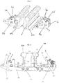
- FIG. 1 shows a perspective view of a device according to the invention in a preferred embodiment, in which a frog point 1 is movably arranged between two wing rails 10a, 10b.
- the wing rails 10a, 10b are detachably connected to a fixed frame 2, which in turn is surrounded by a movable frame 3.
- a frog point 1 is releasably connected.
- the relative movement of the movable frame 3 to the fixed frame 2 is effected via roller arrangements 4, 5 arranged laterally to the wing rails 10a, 10b and mounted in a carrier 3a.
- the roller body 4 are preferably eccentric about the bearing axis 5 rotatably mounted, wherein the longitudinal movement of the movable frame 3 is limited to the fixed frame 2 by slots 13a, 13b.
- FIG. 2 shows a sectional view through a device according to the invention FIG. 1 in which the frog point 1 is seated on the movable frame 3 and is laterally displaceable between two wing rails 10a, 10b, which are detachably connected to a fixed frame 2.
- the rollers 4 are arranged outside of the space B claimed by the wing rails 10a, 10b and are rotatably movable about an eccentric axis 5.
- the rollers 4 run when moving the frog point 1 by the dimension A away from the first wing rail 10b on the second wing rail 10a through a guideway 7 with a central displacement surface 11 and this central displacement surface 11 limiting ramps D.
- FIG. 3 shows a plan view of the device according to the invention, in which the wing rails and the frog point have been removed for the sake of clarity.
- the fixed frame 2 is arranged centrally within the movable frame 3, wherein the rollers 4 are connected to the movable frame 3 and could roll over connected to the fixed frame 2 guideways 7.
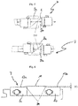
- FIG. 4 shows a sectional detailed view of a guideway 7 with two complementary shaped and mutually mounted, angled to the longitudinal direction of the guideway 7 stop surfaces C.
- the stop surfaces C are formed by mutually displaceable parts 8a, 8b of the guideway 7, which are fixable to each other via connecting elements 9 in position ,
- FIG. 5 shows two states in which the parts 8a, 8b of the guideway 7 are different from each other in the longitudinal direction E shifted from each other.
- FIG. 6 Finally, a side view of the guideway 7 from FIG. 5 consisting of the abutting parts 8a, 8b.
- a central displacement surface 11 is laterally adjacent to two settling surfaces 12a, 12b, the height difference between the central displacement surface 11 and the lateral settling surfaces 12a, 12b corresponding to the dimension F.
- the transition from the lateral Absetz vom 12a, 12b to the central displacement surface 11 is formed by ramps D, on the (not shown) role in the transition from the first lateral Absetz constitutional 12a on the sliding surface 11 across the second contact surface 12b easily and without entanglement or unwind tension.
Landscapes
- Engineering & Computer Science (AREA)
- Mechanical Engineering (AREA)
- Architecture (AREA)
- Civil Engineering (AREA)
- Structural Engineering (AREA)
- Bearings For Parts Moving Linearly (AREA)
- Refuge Islands, Traffic Blockers, Or Guard Fence (AREA)
- Current-Collector Devices For Electrically Propelled Vehicles (AREA)
- Blinds (AREA)
- Mechanisms For Operating Contacts (AREA)
- Train Traffic Observation, Control, And Security (AREA)
Description
- Die Erfindung betrifft eine Vorrichtung zum Verschieben einer zwischen zwei Flügelschienen beweglichen Herzstückspitze einer Gleisanlage bzw. Eisenbahnweiche, umfassend zumindest eine derartige Vorrichtung, wobei die Flügelschienen mit einem feststehenden Rahmen und die Herzstückspitze mit einem beweglichen Rahmen verbunden sind und der bewegliche Rahmen relativ zum feststehenden Rahmen über eine außerhalb des von den Flügelschienen aufgespannten Raums angeordnete Rollenanordnung verschiebbar gelagert ist.
- Eine Vorrichtung der eingangs genannten Art zum Verschieben einer Herzstückspitze einer Gleisanlage mit räumlich von der Rollenlagerung entkoppelter Herzstückspitze ist durch die
WO 2010/112355 A1 bekannt geworden. - Ein Hauptnachteil der bekannten Lösung ist, dass die bei der Bewegung zwischen einer ersten Stellung und einer zweiten Stellung angehobene Herzstückspitze auf einem in Sonderbauweise ausgebildeten, den beweglichen Rahmen bereit stellenden Bügel und dort auf einer erhöhten Aufnahme bzw. einem Sockel angeordnet ist. Der Aufschlag der Herzstückspitze an der einen oder der anderen Flügelschiene erlaubt keine Möglichkeit für Variationen zur Positionierung.
- Der Erfindung liegt daher die Aufgabe zugrunde, die bekannten Vorrichtungen zum Verschieben einer zwischen zwei Flügelschienen beweglichen Herzstückspitze einer Gleisanlage so weiterzubilden, dass die aus dem Stand der Technik bekannten Nachteile überwunden werden.
- Diese Aufgabe wird im erfindungsgemäßen Sinne mittels einer Vorrichtung, umfassen die Merkmale des Anspruchs 1, sowie mit einer Gleisanlage, umfassend die Merkmale des Anspruchs 7, gelöst. Vorteilhafte Ausgestaltungen der Erfindungen sind in den abhängigen Ansprüchen definiert.
- Gemäß der Erfindung weist die Vorrichtung vorzugsweise der feststehende Rahmen, wenigstens eine Führungsbahn zum Führen der Bewegung des beweglichen Rahmens relativ zum feststehenden Rahmen auf. Besonders bevorzugt wird, wenn die Relativbewegung des beweglichen Rahmens durch geeignete Anschlagelemente begrenzbar ist, beispielsweise durch in Langlöchern geführte Stifte oder durch die Bereitstellung von an dem feststehenden Rahmen angeordneten Anschlagstücken. In jedem Fall wird die Relativbewegung des beweglichen Rahmens zum feststehenden Rahmen mit besonders einfachen Mitteln unterstützt, um die Verschiebung der Herzstückspitze in der gewünschten Weise und ohne Abweichungen zu ermöglichen.
- Erfindungsgemäß umfasst. der bewegliche Rahmen und der feststehende Rahmen, vorzugsweise die wenigstens eine Führungsbahn, zwei gegeneinander gelagerte und zur Längsrichtung der Fahrbahn abgewinkelte Anschlagflächen über die die Positionierung der Ausgangslage des beweglichen Rahmens innerhalb des feststehenden Rahmens besonders sicher gewährleistet werden kann. Durch Vorsehen der zueinander komplementär gestalteten schrägen Flächen wird eine Verschiebung der Flächen in der Längsrichtung zueinander zwangsläufig auch eine Verstellung der Position der einzustellenden Elemente zueinander senkrecht zu der Längsrichtungsbewirkung. Der Rollenweg ist damit gezielt in Abhängigkeit vom Aufschlag der Herzstückspitze einstellbar. Besonders bevorzugt wird in diesem Zusammenhang, wenn geeignete Feststellmittel, beispielsweise Schrauben, den feststehenden Rahmen und den beweglichen Rahmen zueinander in einer vorab festgelegten Position fixieren.
- In der bevorzugten Ausführungsform der Erfindung umfasst die Rollenanordnung zumindest eine exzentrisch gelagerte Rolle. Hierdurch wird mit besonders einfachen Mitteln ermöglicht, dass die Horizontalverschiebung der Herzstückspitze zwischen den zwei Flügelschienen der Gleisanlage mit einer Bewegungskomponente in die Vertikale unterstützt wird, um hierdurch die Reibung zwischen dem beweglichen Rahmen und dem feststehenden Rahmen zu minimieren oder vollständig zu vermeiden. Hierdurch wird eine dauerhaft und im Wesentlichen verschleißfrei funktionierende Vorrichtung mit besonders einfachen und gegebenenfalls leicht auszutauschenden Mitteln erhalten.
- Nach einer Ausgestaltung der Erfindung kann vorgesehen werden, dass die wenigstens eine Führungsbahn zwei seitlich zu einer zentralen Verschiebefläche angeordnete Absetzflächen aufweist und die zentrale Verschiebefläche einen definierten Höhenunterschied gegenüber den Absetzflächen aufweist. Dabei wird bevorzugt, wenn der Übergang zwischen der zentralen Verschiebefläche und den Absetzflächen über Rampen mit einer definierten Steigung erfolgt. Hierdurch wird gewährleistet, dass beim Überfahren der Führungsbahn mittels der Rolleneinrichtung zwangsläufig eine Anhebung des beweglichen Rahmens und der hiermit verbundenen Herzstückspitze zumindest um das Maß des definierten Höhenunterschieds, und die Verschiebung der Herzstückspitze beim Überfahren der zentralen Verschiebefläche mit den Rollen mit geringstmöglicher Reibung erfolgt. Schließlich erfolgt in einem letzten Schritt der Verschiebung der Herzstückspitze das Verlassen der zentralen Verschiebefläche und das Absetzen der Rolleinrichtung auf der zweiten Absetzfläche. Auch bei diesem letzten Schritt erfolgt eine Vertikalbewegung des beweglichen Rahmen relativ zum feststehenden Rahmen um das Maß des definierten Höhenunterschieds zwischen der zentralen Verschiebefläche und den Absetzflächen, wodurch die Herzstückspitze vorzugsweise in ihrer vorgesehenen Position anliegend an der zweiten Flügelschiene arretiert ist.
- Durch das Vorsehen von Rampen zwischen den seitlich Aufsetzflächen und der zentralen Verschiebefläche wird überdies ein unerwünschtes seitliches Verschieben der Herzstückspitze von ihrer Absetzposition mit besonders einfachen Mitteln erschwert. Besonders bevorzugt wird in diesem Zusammenhang auch, wenn die Summe aus Breite der zentralen Verschiebefläche und Breite der Rampen kleiner oder gleich dem Verschiebemaß der Herzstückspitze zwischen den Flügelschienen ist. Somit wird in geeigneter Weise eine vorteilhafte Abstimmung zwischen den Abmessungen der Führungsbahn und dem Verschiebemaß für die Herzstückspitze innerhalb der Gleisweiche erreicht.
- Die Erfindung betrifft zudem eine Gleisweiche mit zumindest einer oben beschriebenen Vorrichtung. Dementsprechend sind sämtliche mit der erfindungsgemäßen Vorrichtung verbundenen Vorteile und Effekte auch mit einer erfindungsgemäßen Gleisweiche erzielbar.
- Die Erfindung wird nachfolgend unter Verweis auf 5 Figuren näher erläutert, in denen
- Fig. 1
- eine perspektivische Draufsicht auf eine erfindungsgemäße Vorrichtung zeigt,
- Fig. 2
- eine geschnittene Ansicht durch die erfindungsgemäße Vorrichtung aus
Figur 1 zeigt, - Fig. 3
- eine Draufsicht auf eine erfindungsgemäße Vorrichtung zeigt,
- Fig. 4
- eine geschnittene Teilansicht der Vorrichtung aus
Figur 3 zeigt, - Fig. 5
- eine Draufsicht auf die Vorrichtung gemäß
Figur 4 in zwei verschiedenen Einstellzuständen zeigt, und - Fig.6
- eine Seitenansicht einer Führungsbahn zeigt.
-
Figur 1 zeigt eine perspektivische Ansicht einer erfindungsgemäßen Vorrichtung in einer bevorzugten Ausführungsform, in der eine Herzstückspitze 1 beweglich zwischen zwei Flügelschienen 10a, 10b angeordnet ist. Die Flügelschienen 10a, 10b sind lösbar mit einem feststehenden Rahmen 2 verbunden, welcher wiederum von einem beweglichen Rahmen 3 umgeben ist. Mit dem beweglichen Rahmen 3 ist eine Herzstückspitze 1 lösbar verbunden. Die Relativbewegung des beweglichen Rahmens 3 zum feststehenden Rahmen 2 wird über seitlich zu den Flügelschienen 10a, 10b angeordnete und in einem Träger 3a gelagerte Rollenanordnungen 4, 5 bewirkt. Die Rollenkörper 4 sind dabei vorzugsweise exzentrisch um die Lagerachse 5 drehbar gelagert, wobei die Längsbewegung des beweglichen Rahmens 3 zum feststehenden Rahmen 2 durch Langlöcher 13a, 13b begrenzt ist. -
Figur 2 zeigt eine geschnittene Ansicht durch eine erfindungsgemäße Vorrichtung gemäßeFigur 1 , bei der die Herzstückspitze 1 auf dem beweglichen Rahmen 3 aufsitzt und zwischen zwei Flügelschienen 10a, 10b, welche lösbar mit einem feststehenden Rahmen 2 verbunden sind, seitlich verschiebbar ist. Die Rollen 4 sind außerhalb des von den Flügelschienen 10a, 10b beanspruchten Raums B angeordnet und um eine exzentrische Achse 5 drehbar beweglich. Die Rollen 4 laufen beim Verschieben der Herzstückspitze 1 um das Maß A von der ersten Flügelschiene 10b weg auf die zweite Flügelschiene 10a hin über eine Führungsbahn 7 mit einer zentralen Verschiebefläche 11 und diese zentrale Verschiebefläche 11 begrenzende Rampen D. -
Figur 3 zeigt eine Draufsicht auf die erfindungsgemäße Vorrichtung, bei der die Flügelschienen und die Herzstückspitze aus Gründen der Übersichtlichkeit entfernt wurden. Wie aus dieser Ansicht leicht zu ersehen, ist der feststehende Rahmen 2 zentral innerhalb des beweglichen Rahmens 3 angeordnet, wobei die Rollen 4 mit dem beweglichen Rahmen 3 verbunden sind und über mit dem feststehenden Rahmen 2 verbundene Führungsbahnen 7 abrollen könne. -
Figur 4 zeigt eine geschnittene Detailansicht einer Führungsbahn 7 mit zwei komplementär gestalteten und gegeneinander gelagerten, zur Längsrichtung der Führungsbahn 7 abgewinkelten Anschlagflächen C. Die Anschlagflächen C werden gebildet durch zueinander verschiebbare Teile 8a, 8b der Führungsbahn 7, welche über Verbindungselemente 9 in ihrer Lage zueinander fixierbar sind. -
Figur 5 zeigt zwei Zustände, in denen die Teile 8a, 8b der Führungsbahn 7 unterschiedlich weit zueinander in Längsrichtung E zueinander verschoben sind. Durch die Verschiebung der Teile 8a, 8b in Längsrichtung E wird zwangsläufig ein Abgleiten der Teile 8a, 8b entlang der Anschlagfläche C mit einer daraus resultierenden Bewegungsrichtung der Teile 8a, 8b senkrecht zur Längsrichtung E bewirkt. Hierdurch kann mit besonders einfachen und wirksamen Mitteln eine Justierung des (nicht dargestellten) feststehenden Rahmens zum (nicht dargestellten) beweglichen Rahmen und die Einstellbarkeit des Rollenweges in Abhängigkeit vom Aufschlag der Herzstückspitze 1 bewirkt werden. -
Figur 6 zeigt schließlich eine Seitenansicht auf die Führungsbahn 7 ausFigur 5 , bestehend aus den aneinander anlegenden Teilen 8a, 8b. In der Seitenansicht ist deutlich zu erkennen, dass eine zentrale Verschiebefläche 11 seitlich von zwei Absetzflächen 12a, 12b benachbart ist, wobei der Höhenunterschied zwischen der zentralen Verschiebefläche 11 und den seitlichen Absetzflächen 12a, 12b dem Maß F entspricht. Der Übergang von den seitlichen Absetzflächen 12a, 12b zu der zentralen Verschiebefläche 11 wird von Rampen D gebildet, über die die (nicht dargestellte) Rolle beim Übergang von der ersten seitlichen Absetzfläche 12a über die Verschiebefläche 11 hinweg zu der zweiten Aufsetzfläche 12b leicht und ohne Verhaken oder Verspannungen abrollen kann. -
- 1
- Herzstückspitze
- 2
- feststehender Rahmen
- 3
- beweglicher Rahmen
- 4
- Rollen
- 5
- exzentrische Achse
- 6
- Flügelschienen
- 7
- Führungsbahn
- 8a
- anliegende Teile
- 8b
- anliegende Teile
- 9
- Verbindungselement
- 10a
- Flügelschiene
- 10b
- Flügelschiene
- 11
- Verschiebefläche
- 12a
- Absetzfläche
- 12b
- Absetzfläche
- 13a
- Langlöcher
- 13b
- Langlöcher
- A
- Maß der Verschiebung
- B
- beanspruchter Raum
- C
- Anschlagfläche
- D
- Rampe
- E
- Längsrichtung
- F
- Maß des Höhenunterschieds
Claims (7)
- Vorrichtung zum Verschieben einer zwischen zwei Flügelschienen (10a,10b) beweglichen Herzstückspitze (1) einer Gleisanlage, wobei die Flügelschienen (10a,10b) mit einem feststehenden Rahmen (2) und die Herzstückspitze (1) mit einem beweglichen Rahmen (3) verbunden sind und der bewegliche Rahmen (3) relativ zum feststehenden Rahmen (2) über eine außerhalb des von den Flügelschienen (10a,10b) aufgespannten Raums (B) angeordnete Rollenanordnung (4,5) verschiebbar gelagert ist,
dadurch gekennzeichnet,
dass der feststehende Rahmen (2) wenigstens eine Führungsbahn (7) zum Führen der Bewegung des beweglichen Rahmens (3) relativ zum feststehenden Rahmen (2) aufweist, wobei der bewegliche Rahmen (3) und der feststehende Rahmen (2), vorzugsweise die wenigstens eine Führungsbahn (7), zwei gegeneinander gelagerte und zur Längsrichtung (E) der Führungsbahn (7) abgewinkelte Anschlagflächen (C) umfassen. - Vorrichtung nach Anspruch 1, dadurch gekennzeichnet, dass die Rollenanordnung (4,5) wenigstens eine exzentrisch gelagerte Rolle (4) umfasst.
- Vorrichtung nach Anspruch 1 oder 2,
dadurch gekennzeichnet, dass die wenigstens eine Führungsbahn (7) zwei seitlich zu einer zentralen Verschiebefläche (11) angeordnete Absetzflächen (12a,12b) aufweist und die zentrale Verschiebefläche (11) einen definierten Höhenunterschied (F) gegenüber den Absetzflächen (12a,12b) aufweist. - Vorrichtung nach Anspruch 3,
dadurch gekennzeichnet, dass Rampen (D) zwischen der zentralen Verschiebefläche (11) und den Absetzflächen (12a,12b) vorgesehen sind. - Vorrichtung nach Anspruch 4, dadurch gekennzeichnet, dass die Summe aus der Breite der zentralen Verschiebefläche (11) und der Breite der Rampen (D) kleiner oder gleich dem Verschiebemaß (A) der Herzstückspitze (1) zwischen den Flügelschienen (10a,10b) ist.
- Vorrichtung nach einem der Ansprüche 1 bis 5, dadurch gekennzeichnet, dass die Relativbewegung des bewegliche Rahmens (3) im feststehenden Rahmen (2) durch Anschlagelemente (13a,13b) begrenzbar ist.
- Gleisanlage, umfassend zumindest eine Vorrichtung gemäß einem der voranstehenden Ansprüche.
Applications Claiming Priority (1)
| Application Number | Priority Date | Filing Date | Title |
|---|---|---|---|
| DE102012017982.0A DE102012017982A1 (de) | 2012-09-12 | 2012-09-12 | Herzstückrollvorrichtung |
Publications (3)
| Publication Number | Publication Date |
|---|---|
| EP2708646A2 EP2708646A2 (de) | 2014-03-19 |
| EP2708646A3 EP2708646A3 (de) | 2015-12-16 |
| EP2708646B1 true EP2708646B1 (de) | 2017-03-29 |
Family
ID=49084735
Family Applications (1)
| Application Number | Title | Priority Date | Filing Date |
|---|---|---|---|
| EP13181347.9A Active EP2708646B1 (de) | 2012-09-12 | 2013-08-22 | Herzstückrollvorrichtung |
Country Status (8)
| Country | Link |
|---|---|
| EP (1) | EP2708646B1 (de) |
| BR (1) | BR102013023216B1 (de) |
| DE (1) | DE102012017982A1 (de) |
| ES (1) | ES2626556T3 (de) |
| HU (1) | HUE033537T2 (de) |
| LT (1) | LT2708646T (de) |
| PL (1) | PL2708646T3 (de) |
| RU (1) | RU2623360C2 (de) |
Families Citing this family (3)
| Publication number | Priority date | Publication date | Assignee | Title |
|---|---|---|---|---|
| CN105780613B (zh) * | 2016-02-01 | 2018-09-14 | 同济大学 | 一种提高列车侧向通过速度的道岔 |
| ES2617562B2 (es) * | 2017-03-10 | 2018-04-12 | Jez Sistemas Ferroviarios, S.L. | Dispositivo de maniobra para desvíos ferroviarios con corazón de punta móvil |
| US12359377B1 (en) | 2024-04-10 | 2025-07-15 | voestalpine Railway Systems Nortrak LLC | Switch point roller assembly |
Family Cites Families (9)
| Publication number | Priority date | Publication date | Assignee | Title |
|---|---|---|---|---|
| AT390084B (de) * | 1988-05-20 | 1990-03-12 | Voest Alpine Maschinenbau | Weiche mit einem herzstueck mit beweglicher haupt- und beispitze |
| DE4315559A1 (de) | 1993-05-10 | 1994-11-17 | Butzbacher Weichenbau Gmbh | Herzstückspitze |
| AT6218U1 (de) | 2001-09-11 | 2003-06-25 | Vae Eisenbahnsysteme Gmbh | Rolleinrichtung für eine bewegliche herzstückspitze |
| DE10215280B4 (de) | 2002-02-07 | 2006-01-12 | Schreck-Mieves Gmbh | Herzstückhebevorrichtung |
| AT412350B (de) | 2002-04-23 | 2005-01-25 | Vae Eisenbahnsysteme Gmbh | Rolleinrichtung für eine bewegliche herzstückspitze |
| AT411350B (de) * | 2002-08-13 | 2003-12-29 | Vae Eisenbahnsysteme Gmbh | Weichenantrieb für bewegliche herze |
| ES2265237B1 (es) * | 2004-09-08 | 2007-12-16 | Felguera Melt, S.A. | Dispositivo para la disminucion de los esfuerzos de maniobra en los cruzamientos ferroviarios de punta movil. |
| AT508027B1 (de) * | 2009-03-30 | 2010-10-15 | Enzesfeld Caro Metallwerke Ag | Weiche für eisenbahnanlagen |
| ES1072245Y (es) * | 2010-04-09 | 2010-09-09 | Amurrio Ferrocarril Y Equipos | Dispositivo de encerrojamiento para corazon de punta movil |
-
2012
- 2012-09-12 DE DE102012017982.0A patent/DE102012017982A1/de not_active Withdrawn
-
2013
- 2013-08-22 ES ES13181347.9T patent/ES2626556T3/es active Active
- 2013-08-22 EP EP13181347.9A patent/EP2708646B1/de active Active
- 2013-08-22 PL PL13181347T patent/PL2708646T3/pl unknown
- 2013-08-22 HU HUE13181347A patent/HUE033537T2/hu unknown
- 2013-08-22 LT LTEP13181347.9T patent/LT2708646T/lt unknown
- 2013-09-11 BR BR102013023216-5A patent/BR102013023216B1/pt active IP Right Grant
- 2013-09-11 RU RU2013141797A patent/RU2623360C2/ru active
Non-Patent Citations (1)
| Title |
|---|
| None * |
Also Published As
| Publication number | Publication date |
|---|---|
| ES2626556T3 (es) | 2017-07-25 |
| HUE033537T2 (hu) | 2017-12-28 |
| DE102012017982A1 (de) | 2014-03-13 |
| BR102013023216A2 (pt) | 2014-11-11 |
| RU2013141797A (ru) | 2015-03-20 |
| EP2708646A3 (de) | 2015-12-16 |
| EP2708646A2 (de) | 2014-03-19 |
| LT2708646T (lt) | 2017-06-12 |
| RU2623360C2 (ru) | 2017-06-23 |
| PL2708646T3 (pl) | 2017-09-29 |
| BR102013023216B1 (pt) | 2021-09-21 |
Similar Documents
| Publication | Publication Date | Title |
|---|---|---|
| EP3880922B1 (de) | Führungssystem zur führung eines bewegbar gelagerten türflügels | |
| EP3207200A1 (de) | Laufwagen eines abstellbaren schiebeflügels | |
| EP2487086B1 (de) | Elektrobahn, insbesondere Elektrohängebahn | |
| DE2003845B2 (de) | Startvorrichtung fur Laufwettbe werbe | |
| DE20018390U1 (de) | Schneidzange | |
| EP2604493B1 (de) | Runge für einen Nutzfahrzeugaufbau | |
| WO2012049234A1 (de) | Beschlag für eine schiebetür | |
| EP2708646A2 (de) | Herzstückrollvorrichtung | |
| EP1497498B1 (de) | Rolleinrichtung für eine bewegliche herzstückspitze | |
| DD148070A5 (de) | Gleisbaumaschine mit schotterpfluganordnung | |
| DE2757723A1 (de) | Auf einem ski montierbare bremseinrichtung | |
| EP2045164B1 (de) | Spurführungsvorrichtung für schienengebundene Fahrzeuge und Eisenbahnweiche hierzu | |
| EP2557264B1 (de) | Sektionaltor | |
| EP2261164A2 (de) | Führungseinrichtung mit Mitten- und Geradlaufregelung für einen mit Laufrädern versehenen Kran auf einer Kranbahn mit Kranschienen | |
| DE102021120518A1 (de) | Vorrichtung zum Steuern einer Hubposition eines Hubelements, Behälterbehandlungsvorrichtung und Verfahren zum Einstellen eines Übergangspunktes einer Steuerkurve | |
| EP0698144B1 (de) | Herzstückspitze | |
| DE102012111320B3 (de) | Vorrichtung zur Spurführung von auf Schienen beweglichen Geräten und/oder Maschinen | |
| DE2438756C2 (de) | Gleisweiche, insbesondere Schnellfahrweiche | |
| EP2380464A1 (de) | Höhenverstellbare Aufnahme einer Lagerung eines Bett- oder Untermatratzenbauteils | |
| EP3554912B9 (de) | Transportsystem mit einem seilgezogenen fahrzeug | |
| AT519530B1 (de) | Vorrichtung zum bewegen einer zungenschiene einer weiche | |
| WO1995008672A1 (de) | Stelleinrichtung | |
| DE102007047370A1 (de) | Spurführungsvorrichtung | |
| DE10230489A1 (de) | Elastisch gelagerte Schiene für Schienenfahrzeuge | |
| DE2310551A1 (de) | Vorrichtung zum verholen von schienenfahrzeugen |
Legal Events
| Date | Code | Title | Description |
|---|---|---|---|
| PUAI | Public reference made under article 153(3) epc to a published international application that has entered the european phase |
Free format text: ORIGINAL CODE: 0009012 |
|
| AK | Designated contracting states |
Kind code of ref document: A2 Designated state(s): AL AT BE BG CH CY CZ DE DK EE ES FI FR GB GR HR HU IE IS IT LI LT LU LV MC MK MT NL NO PL PT RO RS SE SI SK SM TR |
|
| AX | Request for extension of the european patent |
Extension state: BA ME |
|
| PUAL | Search report despatched |
Free format text: ORIGINAL CODE: 0009013 |
|
| AK | Designated contracting states |
Kind code of ref document: A3 Designated state(s): AL AT BE BG CH CY CZ DE DK EE ES FI FR GB GR HR HU IE IS IT LI LT LU LV MC MK MT NL NO PL PT RO RS SE SI SK SM TR |
|
| AX | Request for extension of the european patent |
Extension state: BA ME |
|
| RIC1 | Information provided on ipc code assigned before grant |
Ipc: E01B 7/14 20060101AFI20151112BHEP Ipc: B61L 5/02 20060101ALI20151112BHEP |
|
| 17P | Request for examination filed |
Effective date: 20160604 |
|
| RBV | Designated contracting states (corrected) |
Designated state(s): AL AT BE BG CH CY CZ DE DK EE ES FI FR GB GR HR HU IE IS IT LI LT LU LV MC MK MT NL NO PL PT RO RS SE SI SK SM TR |
|
| GRAP | Despatch of communication of intention to grant a patent |
Free format text: ORIGINAL CODE: EPIDOSNIGR1 |
|
| INTG | Intention to grant announced |
Effective date: 20161020 |
|
| GRAS | Grant fee paid |
Free format text: ORIGINAL CODE: EPIDOSNIGR3 |
|
| GRAA | (expected) grant |
Free format text: ORIGINAL CODE: 0009210 |
|
| AK | Designated contracting states |
Kind code of ref document: B1 Designated state(s): AL AT BE BG CH CY CZ DE DK EE ES FI FR GB GR HR HU IE IS IT LI LT LU LV MC MK MT NL NO PL PT RO RS SE SI SK SM TR |
|
| REG | Reference to a national code |
Ref country code: GB Ref legal event code: FG4D Free format text: NOT ENGLISH |
|
| REG | Reference to a national code |
Ref country code: CH Ref legal event code: EP |
|
| REG | Reference to a national code |
Ref country code: AT Ref legal event code: REF Ref document number: 879876 Country of ref document: AT Kind code of ref document: T Effective date: 20170415 |
|
| REG | Reference to a national code |
Ref country code: IE Ref legal event code: FG4D Free format text: LANGUAGE OF EP DOCUMENT: GERMAN |
|
| REG | Reference to a national code |
Ref country code: DE Ref legal event code: R096 Ref document number: 502013006780 Country of ref document: DE |
|
| REG | Reference to a national code |
Ref country code: SE Ref legal event code: TRGR |
|
| REG | Reference to a national code |
Ref country code: CH Ref legal event code: NV Representative=s name: SCHMAUDER AND PARTNER AG PATENT- UND MARKENANW, CH |
|
| REG | Reference to a national code |
Ref country code: RO Ref legal event code: EPE |
|
| REG | Reference to a national code |
Ref country code: NL Ref legal event code: FP |
|
| REG | Reference to a national code |
Ref country code: ES Ref legal event code: FG2A Ref document number: 2626556 Country of ref document: ES Kind code of ref document: T3 Effective date: 20170725 |
|
| PG25 | Lapsed in a contracting state [announced via postgrant information from national office to epo] |
Ref country code: NO Free format text: LAPSE BECAUSE OF FAILURE TO SUBMIT A TRANSLATION OF THE DESCRIPTION OR TO PAY THE FEE WITHIN THE PRESCRIBED TIME-LIMIT Effective date: 20170629 Ref country code: GR Free format text: LAPSE BECAUSE OF FAILURE TO SUBMIT A TRANSLATION OF THE DESCRIPTION OR TO PAY THE FEE WITHIN THE PRESCRIBED TIME-LIMIT Effective date: 20170630 Ref country code: HR Free format text: LAPSE BECAUSE OF FAILURE TO SUBMIT A TRANSLATION OF THE DESCRIPTION OR TO PAY THE FEE WITHIN THE PRESCRIBED TIME-LIMIT Effective date: 20170329 |
|
| REG | Reference to a national code |
Ref country code: FR Ref legal event code: PLFP Year of fee payment: 5 |
|
| PG25 | Lapsed in a contracting state [announced via postgrant information from national office to epo] |
Ref country code: RS Free format text: LAPSE BECAUSE OF FAILURE TO SUBMIT A TRANSLATION OF THE DESCRIPTION OR TO PAY THE FEE WITHIN THE PRESCRIBED TIME-LIMIT Effective date: 20170329 Ref country code: BG Free format text: LAPSE BECAUSE OF FAILURE TO SUBMIT A TRANSLATION OF THE DESCRIPTION OR TO PAY THE FEE WITHIN THE PRESCRIBED TIME-LIMIT Effective date: 20170629 Ref country code: LV Free format text: LAPSE BECAUSE OF FAILURE TO SUBMIT A TRANSLATION OF THE DESCRIPTION OR TO PAY THE FEE WITHIN THE PRESCRIBED TIME-LIMIT Effective date: 20170329 |
|
| PG25 | Lapsed in a contracting state [announced via postgrant information from national office to epo] |
Ref country code: EE Free format text: LAPSE BECAUSE OF FAILURE TO SUBMIT A TRANSLATION OF THE DESCRIPTION OR TO PAY THE FEE WITHIN THE PRESCRIBED TIME-LIMIT Effective date: 20170329 Ref country code: SK Free format text: LAPSE BECAUSE OF FAILURE TO SUBMIT A TRANSLATION OF THE DESCRIPTION OR TO PAY THE FEE WITHIN THE PRESCRIBED TIME-LIMIT Effective date: 20170329 |
|
| PG25 | Lapsed in a contracting state [announced via postgrant information from national office to epo] |
Ref country code: SM Free format text: LAPSE BECAUSE OF FAILURE TO SUBMIT A TRANSLATION OF THE DESCRIPTION OR TO PAY THE FEE WITHIN THE PRESCRIBED TIME-LIMIT Effective date: 20170329 Ref country code: PT Free format text: LAPSE BECAUSE OF FAILURE TO SUBMIT A TRANSLATION OF THE DESCRIPTION OR TO PAY THE FEE WITHIN THE PRESCRIBED TIME-LIMIT Effective date: 20170731 Ref country code: IS Free format text: LAPSE BECAUSE OF FAILURE TO SUBMIT A TRANSLATION OF THE DESCRIPTION OR TO PAY THE FEE WITHIN THE PRESCRIBED TIME-LIMIT Effective date: 20170729 |
|
| REG | Reference to a national code |
Ref country code: HU Ref legal event code: AG4A Ref document number: E033537 Country of ref document: HU |
|
| REG | Reference to a national code |
Ref country code: DE Ref legal event code: R097 Ref document number: 502013006780 Country of ref document: DE |
|
| PG25 | Lapsed in a contracting state [announced via postgrant information from national office to epo] |
Ref country code: DK Free format text: LAPSE BECAUSE OF FAILURE TO SUBMIT A TRANSLATION OF THE DESCRIPTION OR TO PAY THE FEE WITHIN THE PRESCRIBED TIME-LIMIT Effective date: 20170329 |
|
| PLBE | No opposition filed within time limit |
Free format text: ORIGINAL CODE: 0009261 |
|
| STAA | Information on the status of an ep patent application or granted ep patent |
Free format text: STATUS: NO OPPOSITION FILED WITHIN TIME LIMIT |
|
| 26N | No opposition filed |
Effective date: 20180103 |
|
| PG25 | Lapsed in a contracting state [announced via postgrant information from national office to epo] |
Ref country code: MC Free format text: LAPSE BECAUSE OF FAILURE TO SUBMIT A TRANSLATION OF THE DESCRIPTION OR TO PAY THE FEE WITHIN THE PRESCRIBED TIME-LIMIT Effective date: 20170329 |
|
| REG | Reference to a national code |
Ref country code: IE Ref legal event code: MM4A |
|
| PG25 | Lapsed in a contracting state [announced via postgrant information from national office to epo] |
Ref country code: SI Free format text: LAPSE BECAUSE OF FAILURE TO SUBMIT A TRANSLATION OF THE DESCRIPTION OR TO PAY THE FEE WITHIN THE PRESCRIBED TIME-LIMIT Effective date: 20170329 |
|
| PG25 | Lapsed in a contracting state [announced via postgrant information from national office to epo] |
Ref country code: IE Free format text: LAPSE BECAUSE OF NON-PAYMENT OF DUE FEES Effective date: 20170822 |
|
| REG | Reference to a national code |
Ref country code: FR Ref legal event code: PLFP Year of fee payment: 6 |
|
| PG25 | Lapsed in a contracting state [announced via postgrant information from national office to epo] |
Ref country code: MT Free format text: LAPSE BECAUSE OF FAILURE TO SUBMIT A TRANSLATION OF THE DESCRIPTION OR TO PAY THE FEE WITHIN THE PRESCRIBED TIME-LIMIT Effective date: 20170329 |
|
| PG25 | Lapsed in a contracting state [announced via postgrant information from national office to epo] |
Ref country code: CY Free format text: LAPSE BECAUSE OF NON-PAYMENT OF DUE FEES Effective date: 20170329 |
|
| PG25 | Lapsed in a contracting state [announced via postgrant information from national office to epo] |
Ref country code: MK Free format text: LAPSE BECAUSE OF FAILURE TO SUBMIT A TRANSLATION OF THE DESCRIPTION OR TO PAY THE FEE WITHIN THE PRESCRIBED TIME-LIMIT Effective date: 20170329 |
|
| REG | Reference to a national code |
Ref country code: LT Ref legal event code: MM4D Effective date: 20190822 |
|
| PG25 | Lapsed in a contracting state [announced via postgrant information from national office to epo] |
Ref country code: LT Free format text: LAPSE BECAUSE OF NON-PAYMENT OF DUE FEES Effective date: 20190822 |
|
| PG25 | Lapsed in a contracting state [announced via postgrant information from national office to epo] |
Ref country code: AL Free format text: LAPSE BECAUSE OF FAILURE TO SUBMIT A TRANSLATION OF THE DESCRIPTION OR TO PAY THE FEE WITHIN THE PRESCRIBED TIME-LIMIT Effective date: 20170329 |
|
| PGFP | Annual fee paid to national office [announced via postgrant information from national office to epo] |
Ref country code: LU Payment date: 20210819 Year of fee payment: 9 |
|
| PGFP | Annual fee paid to national office [announced via postgrant information from national office to epo] |
Ref country code: FR Payment date: 20210819 Year of fee payment: 9 |
|
| PG25 | Lapsed in a contracting state [announced via postgrant information from national office to epo] |
Ref country code: LU Free format text: LAPSE BECAUSE OF NON-PAYMENT OF DUE FEES Effective date: 20220822 |
|
| P01 | Opt-out of the competence of the unified patent court (upc) registered |
Effective date: 20230517 |
|
| PG25 | Lapsed in a contracting state [announced via postgrant information from national office to epo] |
Ref country code: FR Free format text: LAPSE BECAUSE OF NON-PAYMENT OF DUE FEES Effective date: 20220831 |
|
| PGFP | Annual fee paid to national office [announced via postgrant information from national office to epo] |
Ref country code: NL Payment date: 20260121 Year of fee payment: 13 |
|
| REG | Reference to a national code |
Ref country code: CH Ref legal event code: U11 Free format text: ST27 STATUS EVENT CODE: U-0-0-U10-U11 (AS PROVIDED BY THE NATIONAL OFFICE) Effective date: 20260217 |
|
| PGFP | Annual fee paid to national office [announced via postgrant information from national office to epo] |
Ref country code: HU Payment date: 20260123 Year of fee payment: 13 |
|
| PGFP | Annual fee paid to national office [announced via postgrant information from national office to epo] |
Ref country code: SE Payment date: 20260121 Year of fee payment: 13 |
|
| PGFP | Annual fee paid to national office [announced via postgrant information from national office to epo] |
Ref country code: GB Payment date: 20260123 Year of fee payment: 13 |
|
| PGFP | Annual fee paid to national office [announced via postgrant information from national office to epo] |
Ref country code: ES Payment date: 20260130 Year of fee payment: 13 |
|
| PGFP | Annual fee paid to national office [announced via postgrant information from national office to epo] |
Ref country code: DE Payment date: 20260130 Year of fee payment: 13 |
|
| PGFP | Annual fee paid to national office [announced via postgrant information from national office to epo] |
Ref country code: AT Payment date: 20260202 Year of fee payment: 13 |
|
| PGFP | Annual fee paid to national office [announced via postgrant information from national office to epo] |
Ref country code: FI Payment date: 20260129 Year of fee payment: 13 Ref country code: RO Payment date: 20260127 Year of fee payment: 13 Ref country code: BE Payment date: 20260130 Year of fee payment: 13 Ref country code: IT Payment date: 20260126 Year of fee payment: 13 |
|
| PGFP | Annual fee paid to national office [announced via postgrant information from national office to epo] |
Ref country code: TR Payment date: 20260123 Year of fee payment: 13 |
|
| PGFP | Annual fee paid to national office [announced via postgrant information from national office to epo] |
Ref country code: CZ Payment date: 20260127 Year of fee payment: 13 Ref country code: CH Payment date: 20260217 Year of fee payment: 13 |
|
| PGFP | Annual fee paid to national office [announced via postgrant information from national office to epo] |
Ref country code: PL Payment date: 20260122 Year of fee payment: 13 |