EP2708425A1 - Elektrische Lenkverriegelung - Google Patents
Elektrische Lenkverriegelung Download PDFInfo
- Publication number
- EP2708425A1 EP2708425A1 EP13004160.1A EP13004160A EP2708425A1 EP 2708425 A1 EP2708425 A1 EP 2708425A1 EP 13004160 A EP13004160 A EP 13004160A EP 2708425 A1 EP2708425 A1 EP 2708425A1
- Authority
- EP
- European Patent Office
- Prior art keywords
- housing
- steering lock
- guide elements
- locking pin
- electric steering
- Prior art date
- Legal status (The legal status is an assumption and is not a legal conclusion. Google has not performed a legal analysis and makes no representation as to the accuracy of the status listed.)
- Granted
Links
- 238000009434 installation Methods 0.000 claims abstract description 7
- 229910000861 Mg alloy Inorganic materials 0.000 claims description 3
- 230000000903 blocking effect Effects 0.000 description 4
- 238000004519 manufacturing process Methods 0.000 description 3
- 238000006073 displacement reaction Methods 0.000 description 2
- 238000000034 method Methods 0.000 description 2
- 239000007787 solid Substances 0.000 description 2
- 238000010276 construction Methods 0.000 description 1
- 238000011161 development Methods 0.000 description 1
- 230000018109 developmental process Effects 0.000 description 1
- 238000007688 edging Methods 0.000 description 1
- 238000001746 injection moulding Methods 0.000 description 1
- 238000003780 insertion Methods 0.000 description 1
- 230000037431 insertion Effects 0.000 description 1
- 230000010354 integration Effects 0.000 description 1
- 230000007257 malfunction Effects 0.000 description 1
- 229910052751 metal Inorganic materials 0.000 description 1
- 239000002184 metal Substances 0.000 description 1
- 238000005457 optimization Methods 0.000 description 1
- 230000003014 reinforcing effect Effects 0.000 description 1
Images


Classifications
-
- B—PERFORMING OPERATIONS; TRANSPORTING
- B60—VEHICLES IN GENERAL
- B60R—VEHICLES, VEHICLE FITTINGS, OR VEHICLE PARTS, NOT OTHERWISE PROVIDED FOR
- B60R25/00—Fittings or systems for preventing or indicating unauthorised use or theft of vehicles
- B60R25/01—Fittings or systems for preventing or indicating unauthorised use or theft of vehicles operating on vehicle systems or fittings, e.g. on doors, seats or windscreens
- B60R25/02—Fittings or systems for preventing or indicating unauthorised use or theft of vehicles operating on vehicle systems or fittings, e.g. on doors, seats or windscreens operating on the steering mechanism
- B60R25/021—Fittings or systems for preventing or indicating unauthorised use or theft of vehicles operating on vehicle systems or fittings, e.g. on doors, seats or windscreens operating on the steering mechanism restraining movement of the steering column or steering wheel hub, e.g. restraining means controlled by ignition switch
- B60R25/0215—Fittings or systems for preventing or indicating unauthorised use or theft of vehicles operating on vehicle systems or fittings, e.g. on doors, seats or windscreens operating on the steering mechanism restraining movement of the steering column or steering wheel hub, e.g. restraining means controlled by ignition switch using electric means, e.g. electric motors or solenoids
- B60R25/02153—Fittings or systems for preventing or indicating unauthorised use or theft of vehicles operating on vehicle systems or fittings, e.g. on doors, seats or windscreens operating on the steering mechanism restraining movement of the steering column or steering wheel hub, e.g. restraining means controlled by ignition switch using electric means, e.g. electric motors or solenoids comprising a locking member radially and linearly moved towards the steering column
Definitions
- the invention relates to an electric steering lock for a vehicle with a locking pin, which is arranged in a lightweight housing and is supported by a steering column-side housing support against violent unlocking.
- Electric steering locks are known from the prior art, in which the steering lock is driven for example by an electric motor or an electromagnet.
- the electric motor or the electromagnet is operated only for unlocking if coded data of an electronic key or a permission card recognized as correct.
- Such a steering lock has a movable between a first and a second end position locking pin for locking a steering shaft in a steering column.
- the locking pin is in the first position, the so-called blocking position, in blocking engagement with the steering shaft engageable and is in the second position, the so-called release position, out of engagement with the steering wheel shaft.
- the locking pin is movable, for example, by the electric motor, which is operated by applying electrical voltage in the respective direction of rotation.
- the locking device is solid, for example, with an existing metal, attachable to the steering column housing for receiving the drive and the locking pin.
- Such a locking device for a Motor vehicle is out of the DE 102 46 225 A1 known.
- the structure comprises a metallic insert, which is accommodated at least partially in the contact region, and an outer holanalysis made of plastic, which is molded onto the metallic insert.
- the present invention has the object, an electric steering lock, wherein the bolt guide is at least partially associated with a steering column-side housing support, and a housing support for receiving a corresponding electric steering lock available provide that avoid the disadvantages of the prior art. Furthermore, the devices according to the invention should be simple and inexpensive to manufacture. Finally, the electric steering lock should still have a transport protection before installation.
- an electric steering lock in which the bolt guide is at least partially associated with a steering column-side housing carrier, and a housing support for receiving a corresponding electrical steering lock provided that avoid the disadvantages of the prior art.
- the devices according to the invention are simple and inexpensive to manufacture and have a transport protection before installation.
- a preferred embodiment of the invention provides that the locking pin does not protrude in its release position or only slightly above the partial guide elements. As a result, the locking pin is effectively protected against damage during transport and installation.
- a further preferred embodiment of the invention provides that the partial guide elements are at least partially extended into the housing interior. This allows a guide over at least a majority of the displacement of the locking pin.
- the partial guide elements each guide the locking pin only on its narrow sides or in the steering column axis direction. Since the partial guide elements are provided only for a small force introduction into the lightweight housing, possible transverse forces acting on a locking pin are not absorbed via the partial guide elements but via the housing carrier.
- a further preferred embodiment of the invention provides that at least the lower housing part and / or the partial guide elements are made of plastic. This represents a cost and weight-optimized method of production.
- the partial guide elements are designed as opposing U-shaped rails with stiffening webs. This can be advantageous in particular in the case of a substantially rectangular or stepped locking bolt cross section.
- a preferred embodiment of the invention provides that the partial guide elements are formed integrally with the lower housing part. This leads to a further cost and weight optimization.
- a preferred embodiment of the invention provides that the partial guide elements have a clearance fit with the locking pin. This allows unhindered displacement of the locking pin.
- a further preferred embodiment of the invention provides that the locking pin is formed as a substantially rectangular profile, wherein its the U-shaped rails of the partial guide elements facing narrow sides have optional recesses.
- the optional recesses create a stepped cross-section.
- a preferred embodiment of the invention provides that the partial guide elements can be integrated for receiving in the housing carrier.
- a trough-shaped housing support for receiving an electric steering lock with a lightweight housing on a guide shaft for receiving a locking pin with partial guide elements.
- a preferred embodiment of the housing support provides that lateral guide flanks are provided in the guide shaft. These can serve for receiving the shear forces acting on the locking pin.
- a further preferred embodiment of the housing support provides that at the free end of the guide shaft, a circumferential end band is provided. This can provide an optimized force flow at the location with the largest forces introduced via the locking pin and the longest lever of the partial guide elements.
- the housing support provides that the guide flanks have a guide length of 15mm to 50mm, preferably 28mm. However, the lengths may vary depending on the length of the locking pin.
- a preferred embodiment of the housing support provides that the housing support is made in one piece with the guide shaft, guide flanks and end band made of a magnesium alloy. This represents a particularly safe construction.
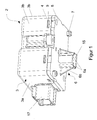
- FIGS. 1 to 6 show a preferred embodiment of an electric steering lock 1 according to the present invention.
- the electric steering lock 1 has a drive unit, a locking pin 15 and a housing 2 made of plastic by injection molding.
- the housing 2 is formed in two parts from an upper housing part 3 and a lower housing part 5.
- a passage opening for the locking pin 15 is provided.
- partial guide elements 6 are arranged for the locking pin 15 on the outside of the housing base 5, of this projecting vertically. These partial guide elements 6 also extend at least partially into the housing and thus ensure the guidance of the locking bolt over its entire travel path.
- the partial guide elements 6 are formed so long that the locking pin 15 protrudes only slightly in a release position on the partial guide elements 6 so as to protect the locking pin 15 during transport.
- the partial guide elements 6 are in turn made of plastic and guide the substantially rectangular locking pin 15 only on its narrow sides, i. they absorb forces essentially only in the steering column axis direction. To increase the rigidity of the partial guide elements 6, these are formed as U-shaped rails 6a with stiffening webs 6b. In this embodiment, the stiffening webs 6b are wedge-shaped. The partial guide elements 6 and the stiffening webs 6b are integrally formed with the housing lower part 5.
- the locking pin 15 has a cuboid shape and has a substantially rectangular cross-section, wherein its the U-shaped rails 6a facing narrow sides have recesses 15a.
- the housing 2, the drive unit and the locking pin 15 is complementarily connectable as a unit with the housing support 10.
- Attachment holes 8 arranged and formed on the underside of the housing base 5 cylindrical centerings 7. As a result, a simple, accurately fitting and unmistakable assembly of the housing 2 is provided on a housing support 10.
- the housing support 10 made of a magnesium alloy is trough-shaped and has centering holes 11, housing support fixing holes 12 and a guide passage opening 13.
- the guide passage opening 13 is provided substantially centrally on a bottom surface of the housing support 10.
- the centering holes 11 and the housing support fixing holes 12 are also arranged in the bottom surface of the housing support 10. Due to the centering holes 11, the cylindrical centerings 7 of the housing 2 are accommodated on the inside at the exact fit.
- the housing support mounting holes 12 are also arranged asymmetrically as the mounting holes 8. As a result, the housing 2 with the housing support 10 can be screwed together confusion.
- lateral guide flanks 18 for laterally guiding and supporting the locking bolt 15 are formed. These guide flanks 18 extend into the housing 2 when the housing 2 is mounted on the housing carrier 10.
- the guide flanks 18 have depending on the length of the locking bolt a flank length of 15 to 50 mm, preferably 28 mm.
- the guide flanks 18 are formed in one piece with the housing carrier 10 in this embodiment.
- the guide flanks 18 surround the locking pin 15 as circumferential endband 19 completely.
- the guide flanks 18 and the cover strip 19 integrally connected thereto serve to receive the transverse forces acting on the locking bolt in the event of a violent unlocking attempt of the steering lock and to transfer them to the housing carrier.
- wedge-shaped ending webs projecting vertically in the direction of the upper housing part 3 are formed as clips 9 both on the longitudinal sides and on the transverse sides.
- the upper housing part 3 has a cuboid basic shape. Slit-shaped incisions are formed as clamping recesses 4 on a front surface 3a, the side surfaces 3b and a rear surface 3c.
- a recess for receiving a plug 17 is provided on the upper housing part 3.
Landscapes
- Engineering & Computer Science (AREA)
- Mechanical Engineering (AREA)
- Lock And Its Accessories (AREA)
- Steering Controls (AREA)
Abstract
Description
- Die Erfindung betrifft eine elektrische Lenkverriegelung für ein Fahrzeug mit einem Sperrbolzen, der in einem Leichtbaugehäuse angeordnet ist und durch einen Lenksäulen-seitigen Gehäuseträger gegen gewaltsames Entsperren abgestützt wird.
- Aus dem Stand der Technik sind elektrische Lenkverriegelungen bekannt, bei denen die Lenkverriegelung beispielsweise durch einen Elektromotor oder einen Elektromagneten angetrieben wird. Dabei wird der Elektromotor oder der Elektromagnet nur dann zur Entriegelung betrieben, wenn codierte Daten eines elektronischen Schlüssels oder einer Berechtigungskarte als richtig erkannt.
- Eine derartige Lenkverriegelung weist einen zwischen einer ersten und einer zweiten Endposition bewegbaren Sperrbolzen zur Verriegelung einer Lenkwelle in einer Lenksäule auf. Der Sperrbolzen ist in der ersten Position, der sogenannten Sperrstellung, in blockierenden Eingriff mit der Lenkwelle bringbar und steht in der zweiten Position, der sogenannten Freigabestellung, außer Eingriff mit der Lenkradwelle. Der Sperrbolzen ist beispielsweise durch den Elektromotor, der durch Anlegen von elektrischer Spannung in der jeweiligen Drehrichtung betrieben wird, bewegbar.
- Um einen höheren Diebstahlschutz für ein Kraftfahrzeug zur Verfügung zu stellen, ist die Verriegelungseinrichtung massiv ausgestaltet, beispielsweise mit einem aus Metall bestehenden, an der Lenksäule anbringbarem Gehäuse zur Aufnahme des Antriebs sowie des Sperrbolzens. Eine solche Verriegelungseinrichtung für ein Kraftfahrzeug ist aus der
DE 102 46 225 A1 bekannt. - Des Weiteren ist aus der
DE 10 2011 012 040 A1 eine elektrische Verriegelungseinrichtung bekannt, bei der ein Sperrbolzen der Lenksäule zugeordnet ist. Dadurch kann das Gehäuse der Verriegelungseinrichtung weniger massiv ausgebildet sein. - Schließlich ist aus der
EP 1982 877 A2 eine elektrische Verriegelungseinrichtung mit einer Struktur aus einem Aufnahmebereich und einem Anlagebereich zur Aufnahme einer Lenkstange bekannt. Hierbei umfasst die Struktur eine metallische Einlage, welche zumindest teilweise in dem Anlagebereich aufgenommen ist, und einen äußeren Holkörper aus Kunststoff, der an die metallische Einlage angespritzt ist. - Vor dem Hintergrund von Kosteneinsparungen und unterschiedlichen Sicherheitsanforderungen an eine Lenkverriegelung, wird seitens der Kfz-Hersteller inzwischen auch eine Lenkverriegelungsvariante mit Leichtbaugehäuse gefordert, bei dem die Führung des Sperrbolzens Lenksäulen-seitig in einem Gehäuseträger erfolgen soll. Dies erfordert allerdings hohe Passgenauigkeit der Lenksäulen-seitigen Sperrbolzenführung, da das rückwärtige Ende des Sperrbolzens i.d.R. über einen Betätiger in die Hubkurve eines Antriebsrads eingreift. Sofern die hierfür erforderliche Passgenauigkeit nicht gewährleistet werden kann, führt dies zu einer Fehlfunktion der Lenkverriegelung. Ferner hat diese Ausgestaltung den Nachteil, dass der Sperrbolzen ohne Führung aus dem Leichtbaugehäuse hervorsteht und so anfällig für Beschädigung bei Transport und Montage ist.
- Daher liegt der vorliegenden Erfindung die Aufgabe zugrunde, eine elektrische Lenkverriegelung, bei der die Bolzenführung zumindest teilweise einem Lenksäulen-seitigen Gehäuseträger zugeordnet ist, und einen Gehäuseträger zur Aufnahme einer entsprechenden elektrischen Lenkverriegelung zur Verfügung zu stellen, die die Nachteile des Standes der Technik vermeiden. Ferner sollen die erfindungsgemäßen Vorrichtungen einfach und kostengünstig zu fertigen sein. Schließlich soll die elektrische Lenkverriegelung noch einen Transportschutz vor dem Einbau aufweisen.
- Diese Aufgabe wird durch eine elektrische Lenkverriegelung für ein Fahrzeug mit den Merkmalen des Anspruchs 1 und einen Gehäuseträger zur Aufnahme einer entsprechenden elektrischen Lenkverriegelung nach Anspruch 11 gelöst. Vorteilhafte Ausführungsformen und Weiterbildungen der Erfindung werden in den Unteransprüchen beschrieben.
- Hierdurch wird eine elektrische Lenkverriegelung, bei der die Bolzenführung zumindest teilweise einem Lenksäulen-seitigen Gehäuseträger zugeordnet ist, und ein Gehäuseträger zur Aufnahme einer entsprechenden elektrischen Lenkverriegelung zur Verfügung gestellt, die die Nachteile des Standes der Technik vermeiden. Ferner sind die erfindungsgemäßen Vorrichtungen einfach und kostengünstig zu fertigen und weisen einen Transportschutz vor dem Einbau auf.
- Erfindungsgemäß weist ein Gehäuse einer elektrische Lenkverriegelung mit einem Leichtbaugehäuse zum Einbau in einen Lenksäulen-seitigen Gehäuseträger ein Gehäuseunterteil auf, an dem eine Antriebseinheit und ein Sperrbolzen angeordnet sind, wobei das Gehäuseunterteil eine Durchtrittsöffnung für den Sperrbolzen und partielle Führungselemente aufweist, die den Sperrbolzenquerschnitt nicht voll umschließen und an der Außenseite des Gehäuseunterteils hervorstehen. Hierdurch wird die Aufgabe derart gelöst, dass die partiellen Führungselemente nur geringe Kräfte auf das Leichtbaugehäuse übertragen aber dennoch den aus dem Gehäuse hervorstehenden Sperrbolzen vor Beschädigung schützen.
- Eine bevorzugte Ausführungsform der Erfindung sieht vor, dass der Sperrbolzen in seiner Freigabestellung nicht oder nur unwesentlich über die partiellen Führungselemente hervorsteht. Dadurch wird der Sperrbolzen bei Transport und Montage wirksam vor Beschädigung geschützt.
- Eine weitere bevorzugte Ausführungsform der Erfindung sieht vor, dass die partiellen Führungselemente zumindest teilweise ins Gehäuseinnere verlängert sind. Dies erlaubt eine Führung über zumindest einen Großteil des Verschiebewegs des Sperrbolzens.
- Noch eine weitere bevorzugte Ausführungsform der Erfindung sieht vor, dass die partiellen Führungselemente den Sperrbolzen jeweils nur an seinen Schmalseiten bzw. in Lenksäulenachsenrichtung führen. Da die partiellen Führungselemente nur für eine geringe Krafteinleitung in das Leichtbaugehäuse vorgesehen sind, werden mögliche auf einen Sperrbolzen wirkende Querkräfte nicht über die partiellen Führungselemente sondern über den Gehäuseträger aufgenommen.
- Ferner sieht eine weitere bevorzugte Ausführungsform der Erfindung vor, dass zumindest das Gehäuseunterteil und/oder die partiellen Führungselemente aus Kunststoff hergestellt sind. Dies stellt eine kosten- und gewichtsoptimierte Herstellungsweise dar.
- Noch eine bevorzugte Ausführungsform der Erfindung sieht vor, dass die partiellen Führungselemente als sich gegenüberliegende U-förmige Schienen mit Versteifungsstegen ausgebildet sind. Dies kann insbesondere bei im Wesentlichen rechteckförmigen oder gestuften Sperrbolzenquerschnitt vorteilhaft sein.
- Eine bevorzugte Ausführungsform der Erfindung sieht vor, dass die partiellen Führungselemente mit dem Gehäuseunterteil einstückig ausgebildet sind. Dies führt zu einer weiteren Kosten und Gewichtsoptimierung.
- Außerdem sieht eine bevorzugte Ausführungsform der Erfindung vor, dass die partiellen Führungselemente mit dem Sperrbolzen eine Spielpassung aufweisen. Dies ermöglicht ein ungehindertes Verschieben des Sperrbolzens.
- Eine weiterhin bevorzugte Ausführungsform der Erfindung sieht vor, dass der Sperrbolzen als ein im Wesentliches rechteckförmiges Profil ausgebildet ist, wobei seine den U-förmigen Schienen der partiellen Führungselemente zugewandten Schmalseiten optionale Aussparungen aufweisen. Durch die optionalen Aussparungen kommt ein gestufter Querschnitt zustande.
- Schließlich sieht eine bevorzugte Ausführungsform der Erfindung vor, dass die partiellen Führungselemente zur Aufnahme in dem Gehäuseträger integrierbar sind.
- Erfindungsgemäß weist ein wannenförmig ausgeformter Gehäuseträger zur Aufnahme einer elektrischen Lenkverriegelung mit einem Leichtbaugehäuse einen Führungsschacht zur Aufnahme eines Sperrbolzens mit partiellen Führungselementen auf. Hierdurch wird eine Lenksäulen-seitige Integration des Gehäuses möglich.
- Eine bevorzugte Ausführungsform des Gehäuseträgers sieht vor, dass in dem Führungsschacht seitliche Führungsflanken vorgesehen sind. Diese können zur Aufnahme vom am Sperrbolzen wirkenden Querkräften dienen.
- Eine weitere bevorzugte Ausführungsform des Gehäuseträgers sieht vor, dass am freien Ende des Führungsschachts ein umlaufendes Abschlussband vorgesehen ist. Dies kann an der Stelle mit den größten über den Sperrbolzen eingeleiteten Kräften und dem längsten Hebel der partiellen Führungselemente für einen optimierten Kraftfluss sorgen.
- Noch eine weitere bevorzugte Ausführungsform des Gehäuseträgers sieht vor, dass die Führungsflanken eine Führungslänge von 15mm bis 50mm, vorzugsweise von 28mm aufweisen. Die Längen können jedoch in Abhängigkeit von der Länge des Sperrbolzens variieren.
- Schließlich sieht eine bevorzugte Ausführungsform des Gehäuseträgers vor, dass der Gehäuseträger einstückig mit dem Führungsschacht, Führungsflanken und Abschlussband aus einer Magnesiumlegierung hergestellt ist. Dies stellt einen besonders sicheren Aufbau dar.
- Nachfolgend wird die Erfindung anhand eines Ausführungsbeispiels zusammen mit den beigefügten Zeichnungen erläutert. Dazu zeigt:
-
Figur 1 eine perspektivische Ansicht eines Gehäuses einer Lenkverriegelung mit einem Sperrbolzen gemäß einer bevorzugten Ausführungsform der vorliegenden Erfindung; -
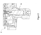
Figur 2 eine Schnittansicht des Gehäuses der Lenkverriegelung gemäß einer bevorzugten Ausführungsform der vorliegenden Erfindung; -
Figur 3 eine perspektivische Ansicht eines Gehäuseträgers der Lenkverriegelung von oben gemäß einer bevorzugten Ausführungsform der vorliegenden Erfindung; -
Figur 4 eine perspektivische Schnittansicht des Gehäuseträgers der Lenkverriegelung gemäß einer bevorzugten Ausführungsform der vorliegenden Erfindung; -
Figur 5 eine perspektivische Ansicht der Lenkverriegelung gemäß einer bevorzugten Ausführungsform der vorliegenden Erfindung; -
Figur 6 eine Schnittdarstellung der Lenkverriegelung gemäß einer bevorzugten Ausführungsform der vorliegenden Erfindung und -
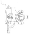
Figur 7 eine perspektivische Ansicht der Lenkverriegelung gemäß einer bevorzugten Ausführungsform der vorliegenden Erfindung. - Nachfolgend beziehen sich Richtungsangaben auf die Zeichnungsebene bzw. auf die translatorische Bewegungsrichtung des Sperrbolzens sofern sich aus dem Text nichts anderes ergibt.
- Die
Figuren 1 bis 6 zeigen eine bevorzugte Ausführungsform einer elektrischen Lenkverriegelung 1 gemäß der vorliegenden Erfindung. - Die elektrische Lenkverriegelung 1 weist eine Antriebseinheit, einen Sperrbolzen 15 und ein aus Kunststoff im Spritzgußverfahren hergestelltes Gehäuse 2 auf. Das Gehäuse 2 ist zweiteilig aus einem Gehäuseoberteil 3 und einem Gehäuseunterteil 5 ausgebildet.
- An dem Gehäuseunterteil 5 ist eine Durchtrittsöffnung für den Sperrbolzen 15 vorgesehen.
- Zur im Wesentlichen geradlinigen Führung des Sperrbolzens 15 zwischen einer Sperrstellung zur Sperrung einer Lenksäule 20 und einer Freigabestellung zur Freigabe der Lenksäule 20 sind partielle Führungselemente 6 für den Sperrbolzen 15 an der Außenseite des Gehäuseunterteils 5 angeordnet, die von diesem senkrecht hervorstehen. Diese partielle Führungselemente 6 erstrecken sich auch zumindest teilweise in das Gehäuse hinein und stellen so die Führung des Sperrbolzens über seinen gesamten Verfahrweg sicher. Dazu sind die partielle Führungselemente 6 so lang ausgebildet, dass der Sperrbolzen 15 in einer Freigabestellung nur unwesentlich über die partiellen Führungselemente 6 hervorsteht, um so den Sperrbolzen 15 während des Transportes zu schützen.
- Die Partielle Führungselemente 6 sind wiederum aus Kunststoff hergestellt und führen den im Wesentlichen rechteckigen Sperrbolzen 15 jeweils nur an seinen Schmalseiten, d.h. sie nehmen Kräfte im Wesentlichen nur in Lenksäulenachsenrichtung auf. Zur Erhöhung der Steifigkeit der partielle Führungselemente 6 sind diese als U-förmige Schienen 6a mit Versteifungsstegen 6b ausgebildet. In dieser Ausführungsform sind die Versteifungsstege 6b keilförmig ausgeformt. Dabei sind die partielle Führungselemente 6 und die Versteifungsstege 6b mit dem Gehäuseunterteil 5 einstückig ausgebildet.
- Zwischen den partielle Führungselementen 6 wird der Sperrbolzen 15 an seinen Schmalseiten in den U-förmigen Schienen 6a der partielle Führungselemente 6 mit einer Spielpassung 16 geradlinig geführt. Dadurch wird das Risiko eines Verkantens und Verklemmens des Sperrbolzens 15 während seines im Wesentlichen geradlinigen Verfahrens zwischen einer sogenannten Sperrstellung und einer sogenannten Freigabestellung innerhalb der partielle Führungselemente reduziert und damit die Betriebssicherheit erhöht.
- Der Sperrbolzen 15 weist eine quaderförmige Gestalt auf und weist einen im Wesentlichen rechteckförmigen Querschnitt auf, wobei seine den U-förmigen Schienen 6a zugewandten Schmalseiten Aussparungen 15a aufweisen. Das Gehäuse 2, die Antriebseinheit und der Sperrbolzen 15 ist als eine Einheit mit dem Gehäuseträger 10 komplementär verbindbar.
- Zusätzlich sind im Gehäuseunterteil 5 asymmetrisch angeordnete
- Befestigungslöcher 8 angeordnet und an der Unterseite des Gehäuseunterteils 5 zylinderförmige Zentrierungen 7 ausgebildet. Dadurch wird eine einfache, passgenaue und verwechslungssichere Montage des Gehäuses 2 an einem Gehäuseträger 10 zur Verfügung gestellt.
- Ferner ist der aus einer Magnesiumlegierung hergestellte Gehäuseträger 10 wannenförmig ausgeformt und weist Zentrierbohrungen 11, Gehäuseträgerbefestigungslöcher 12 und eine Führungsdurchtrittsöffnung 13 auf. Die Führungsdurchtrittsöffnung 13 ist im Wesentlichen zentral auf einer Bodenfläche des Gehäuseträgers 10 vorgesehen. Die Zentrierbohrungen 11 und die Gehäuseträgerbefestigungslöcher 12 sind ebenfalls in der Bodenfläche des Gehäuseträgers 10 angeordnet. Durch die Zentrierbohrungen 11 werden die zylinderförmige Zentrierungen 7 des Gehäuses 2 wannenseitig innen passgenau aufgenommen. Die Gehäuseträgerbefestigungslöcher 12 sind ebenfalls asymmetrisch angeordnet wie die Befestigungslöcher 8. Dadurch ist das Gehäuse 2 mit dem Gehäuseträger 10 verwechslungssicher verschraubbar. Von der Führungsdurchtrittsöffnung 13 erstreckt sich senkrecht an der Unterseite der Bodenfläche des Gehäuseträgers 10 nach außen ein Führungsschacht 14 zum Einführen der partiellen Führungselemente 6 des Gehäuses 2. Darin werden sowohl die U-förmige Schienen 6a als auch die Versteifungsstege 6b gehalten und fixiert.
- Ferner sind in dem Führungsschacht 14 quer zur Lenksäulenachsenrichtung seitliche Führungsflanken 18 zum seitlichen Führen und Abstützen des Sperrbolzens 15 ausgebildet. Diese Führungsflanken 18 erstrecken sich bei auf dem Gehäuseträger 10 montiertem Gehäuse 2 in das Gehäuse 2 hinein. Die Führungsflanken 18 weisen je nach Länge des Sperrbolzens eine Flankenlänge von jeweils 15 bis 50 mm, vorzugsweise 28 mm auf. Dabei sind die Führungsflanken 18 in dieser Ausführungsform einstückig mit dem Gehäuseträger 10 ausgebildet. An der Austrittsöffnung des Sperrbolzens 15 aus dem Führungsschacht 14, umschließen die Führungsflanken 18 den Sperrbolzen 15 als umlaufendes Abschlussband 19 vollständig. Die Führungsflanken 18 und das einstückig damit verbundene Abschlussband 19 dienen dazu, im Falle eines gewaltsamen Entriegelungsversuchs der Lenkverriegelung die auf den Sperrbolzen wirkenden Querkräfte aufzunehmen und auf den Gehäuseträger zu übertragen. Hierbei nehmen die aus Kunststoff hergestellten partiellen Führungselemente 6 lediglich geringe Längskräfte auf.
- An dem Gehäuseunterteil 5 sind senkrecht in Richtung Gehäuseoberteil 3 ragende, keilförmig endende Stege als Clips 9 sowohl an den Längsseiten als auch an den Querseiten ausgeformt. Das Gehäuseoberteil 3 weist eine quaderförmige Grundform auf. An einer Vorderfläche 3a, den Seitenflächen 3b und einer Rückfläche 3c sind schlitzförmige Einschnitte als Klemmaussparungen 4 ausgebildet. Zusätzlich ist an dem Gehäuseoberteil 3 eine Aussparung zur Aufnahme eines Steckers 17 vorgesehen. Somit ist das Gehäuseoberteil 3 durch die Clips 9 mit dem Gehäuseunterteil 5 formschlüssig in rastenden Eingriff bringbar.
-
- 1
- elektrische Lenkverriegelung
- 2
- Gehäuse
- 3
- Gehäuseoberteil
- 3a
- Vorderfläche
- 3b
- Seitenfläche
- 3c
- Rückfläche
- 4
- Klemmaussparung
- 5
- Gehäuseunterteil
- 6
- Partielles Führungselement
- 6a
- Schiene
- 6b
- Versteifungssteg
- 7
- Zentrierung
- 8
- Befestigungsloch
- 9
- Clip
- 10
- Gehäuseträger
- 11
- Zentrierbohrung
- 12
- Gehäuseträgerbefestigungsloch
- 13
- Führungsdurchtrittsöffnung
- 14
- Führungsschacht
- 15
- Sperrbolzen
- 15a
- Aussparung
- 16
- Spielpassung
- 17
- Stecker
- 18
- Führungsflanke
- 19
- Abschlussband
- 20
- Lenksäule
Claims (15)
- Elektrische Lenkverriegelung (1) mit einem Leichtbaugehäuse zum Einbau in einen Lenksäulen-seitigen Gehäuseträger, wobei das Gehäuse ein Gehäuseunterteil (5) aufweist, an dem eine Antriebseinheit und ein Sperrbolzen (15) angeordnet sind, wobei das Gehäuseunterteil (5) eine Durchtrittsöffnung für den Sperrbolzen (15) und partielle Führungselemente (6) aufweist, die den Sperrbolzenquerschnitt nicht voll umschließen und an der Außenseite des Gehäuseunterteils (5) hervorstehen.
- Elektrische Lenkverriegelung (1) nach Anspruch 1, wobei der Sperrbolzen (15) in seiner Freigabestellung nicht oder nur unwesentlich über die partiellen Führungselemente (6) hervorsteht.
- Elektrische Lenkverriegelung (1) nach einem der vorhergehenden Ansprüche, wobei die partiellen Führungselemente (6) zumindest teilweise ins Gehäuseinnere verlängert sind.
- Elektrische Lenkverriegelung (1) nach einem der vorhergehenden Ansprüche, wobei die partiellen Führungselemente (6) den Sperrbolzen (15) jeweils nur an seinen Schmalseiten bzw. in Lenksäulenachsenrichtung führen.
- Elektrische Lenkverriegelung (1) nach einem der vorhergehenden Ansprüche, wobei zumindest das Gehäuseunterteil (5) und/oder die partiellen Führungselemente (6) aus Kunststoff hergestellt sind.
- Elektrische Lenkverriegelung (1) nach einem der vorhergehenden Ansprüche, wobei die partiellen Führungselemente (6) als sich gegenüberliegende U-förmige Schienen (6a) mit Versteifungsstegen (6b) ausgebildet sind.
- Elektrische Lenkverriegelung (1) nach einem der vorhergehenden Ansprüche, wobei die partiellen Führungselemente (6) mit dem Gehäuseunterteil (5) einstückig ausgebildet sind.
- Elektrische Lenkverriegelung (1) nach einem der vorhergehenden Ansprüche, wobei die partiellen Führungselemente (6) mit dem Sperrbolzen (15) eine Spielpassung aufweisen.
- Elektrische Lenkverriegelung (1) nach einem der vorhergehenden Ansprüche, wobei der Sperrbolzen (15) als ein im Wesentliches rechteckförmiges Profil ausgebildet ist, wobei seine den U-förmigen Schienen (6a) der partiellen Führungselemente zugewandten Schmalseiten optionale Aussparungen (15a) aufweisen.
- Elektrische Lenkverriegelung (1) nach einem der vorhergehenden Ansprüche, wobei die partiellen Führungselemente (6) zur Aufnahme in dem Gehäuseträger (10) integrierbar sind.
- Gehäuseträger (10) zur Aufnahme einer elektrischen Lenkverriegelung (1) mit einem Leichtbaugehäuse, wobei der Gehäuseträger (10) wannenförmig ausgeformt ist und einen Führungsschacht (14) zur Aufnahme eines Sperrbolzens mit partiellen Führungselementen (6) aufweist.
- Gehäuseträger (10) nach Anspruch 11, wobei in dem Führungsschacht seitliche Führungsflanken (18) vorgesehen sind.
- Gehäuseträger (10) nach Anspruch 11 oder 12, wobei am freien Ende des Führungsschachts (14) ein umlaufendes Abschlussband (19) vorgesehen ist.
- Gehäuseträger (10) nach Anspruch 11 bis 13, wobei die Führungsflanken (18) eine Führungslänge von 15mm bis 50mm, vorzugsweise von 28mm aufweisen.
- Gehäuseträger (10) nach Anspruch 11 oder 14, wobei der Gehäuseträger einstückig mit dem Führungsschacht (14), Führungsflanken (18) und Abschlussband (19) aus einer Magnesiumlegierung hergestellt ist.
Applications Claiming Priority (1)
| Application Number | Priority Date | Filing Date | Title |
|---|---|---|---|
| DE102012018238.4A DE102012018238A1 (de) | 2012-09-17 | 2012-09-17 | Elektrische Lenkverriegelung |
Publications (2)
| Publication Number | Publication Date |
|---|---|
| EP2708425A1 true EP2708425A1 (de) | 2014-03-19 |
| EP2708425B1 EP2708425B1 (de) | 2015-03-04 |
Family
ID=49033787
Family Applications (1)
| Application Number | Title | Priority Date | Filing Date |
|---|---|---|---|
| EP13004160.1A Not-in-force EP2708425B1 (de) | 2012-09-17 | 2013-08-22 | Elektrische Lenkverriegelung |
Country Status (3)
| Country | Link |
|---|---|
| EP (1) | EP2708425B1 (de) |
| CN (1) | CN103661250B (de) |
| DE (1) | DE102012018238A1 (de) |
Citations (5)
| Publication number | Priority date | Publication date | Assignee | Title |
|---|---|---|---|---|
| FR2621874A1 (fr) * | 1987-10-15 | 1989-04-21 | Turatti Mario | Dispositif antivol |
| EP1323600A1 (de) * | 2001-12-12 | 2003-07-02 | Adam Opel Ag | Lenksäulenmodul mit Lenkschlosssicherung |
| WO2006029401A2 (en) * | 2004-09-09 | 2006-03-16 | Stoneridge Control Devices, Inc. | Steering shaft lock actuator |
| DE102006059282A1 (de) * | 2006-12-13 | 2008-06-19 | Huf Hülsbeck & Fürst Gmbh & Co. Kg | Vorrichtung zur Ansteuerung eines Sperrgliedes |
| EP1982877A2 (de) * | 2007-02-09 | 2008-10-22 | TRW Automotive Italia S.p.A | Lenksperre für Fahrzeuge |
Family Cites Families (5)
| Publication number | Priority date | Publication date | Assignee | Title |
|---|---|---|---|---|
| DE10121714C1 (de) * | 2001-05-04 | 2003-01-02 | Huf Huelsbeck & Fuerst Gmbh | Schloß, insbesondere zum Verriegeln der Lenkspindel eines Kraftfahrzeugs |
| DE10246225A1 (de) | 2002-10-04 | 2004-04-15 | Bayerische Motoren Werke Ag | Kraftfahrzeuglenkeinrichtung |
| JP4496031B2 (ja) * | 2004-07-29 | 2010-07-07 | 株式会社東海理化電機製作所 | ステアリングロック装置 |
| DE102011012040A1 (de) | 2010-02-26 | 2011-09-01 | Marquardt Gmbh | Verriegelungseinrichtung, insbesondere für ein Kraftfahrzeug |
| CN202324886U (zh) * | 2011-12-01 | 2012-07-11 | 贾君鑫 | 一种带保险的可换向斜舌锁 |
-
2012
- 2012-09-17 DE DE102012018238.4A patent/DE102012018238A1/de not_active Withdrawn
-
2013
- 2013-08-22 EP EP13004160.1A patent/EP2708425B1/de not_active Not-in-force
- 2013-09-06 CN CN201310403782.9A patent/CN103661250B/zh not_active Expired - Fee Related
Patent Citations (5)
| Publication number | Priority date | Publication date | Assignee | Title |
|---|---|---|---|---|
| FR2621874A1 (fr) * | 1987-10-15 | 1989-04-21 | Turatti Mario | Dispositif antivol |
| EP1323600A1 (de) * | 2001-12-12 | 2003-07-02 | Adam Opel Ag | Lenksäulenmodul mit Lenkschlosssicherung |
| WO2006029401A2 (en) * | 2004-09-09 | 2006-03-16 | Stoneridge Control Devices, Inc. | Steering shaft lock actuator |
| DE102006059282A1 (de) * | 2006-12-13 | 2008-06-19 | Huf Hülsbeck & Fürst Gmbh & Co. Kg | Vorrichtung zur Ansteuerung eines Sperrgliedes |
| EP1982877A2 (de) * | 2007-02-09 | 2008-10-22 | TRW Automotive Italia S.p.A | Lenksperre für Fahrzeuge |
Also Published As
| Publication number | Publication date |
|---|---|
| CN103661250A (zh) | 2014-03-26 |
| DE102012018238A1 (de) | 2014-03-20 |
| CN103661250B (zh) | 2017-08-22 |
| EP2708425B1 (de) | 2015-03-04 |
Similar Documents
| Publication | Publication Date | Title |
|---|---|---|
| EP3642082B1 (de) | Halterung zur befestigung eines sensors, insbesondere radarsensors, an einem fahrzeug und ein system aus einer halterung und dem sensor | |
| EP4244929A1 (de) | Batteriegehäuse, traktionsbatterie und kraftfahrzeug | |
| DE102008059680A1 (de) | Vorrichtung zur Halterung einer Batterie | |
| DE202021102081U1 (de) | Elektrofahrrad mit Zusatzakku und Zusatzakkuanordnung für ein Elektrofahrrad | |
| DE102008052965A1 (de) | Vorrichtung zur Befestigung eines Formhimmels an einem Panorama-oder Schiebedach eines Fahrzeugs | |
| DE102012003617A1 (de) | Gehäuse für ein Steuergerät | |
| DE102008061106A1 (de) | Laderaumabdeckung für ein Fahrzeug | |
| DE102019108882A1 (de) | Halterungsbasisteil zur Befestigung wenigstens eines Kameragehäuses an einem Fahrzeugteil eines Fahrzeugs, Kameragehäuse und Kamerasystem | |
| EP3658415B1 (de) | Vorrichtung zur aufnahme eines gegenstands in einem kraftfahrzeug | |
| EP1398219A2 (de) | Vorrichtung zur Unterbringung eines elektrischen Geräts im Innenraum eines Kraftfahrzeugs | |
| EP1961590B1 (de) | Bauteilhalterung | |
| DE102005002759A1 (de) | Schlittenbaugruppe für einen Fensterheber, insbesondere für Fahrzeuge | |
| EP2708425B1 (de) | Elektrische Lenkverriegelung | |
| EP1253034B1 (de) | Seitenaufprallträger und Kraftfahrzeugtür | |
| EP2892762B1 (de) | Kraftfahrzeug mit einem airbagmodul | |
| EP1323600B1 (de) | Lenksäulenmodul mit Lenkschlosssicherung | |
| DE10340196B4 (de) | Schlossmoduleinrichtung für eine Kraftfahrzeugtür | |
| DE102018107504A1 (de) | Griffvorrichtung | |
| WO2005052290A1 (de) | Türinnenelement für eine kraftfahrzeugtür mit einer als einbruchssicherung dienenden abdeckung | |
| DE102015108737A1 (de) | Kraftfahrzeugschloss | |
| DE19925859B4 (de) | Montagehilfe für eine Kraftfahrzeugtürkonstruktion | |
| WO2015150239A1 (de) | System für ein fahrzeugdach | |
| DE102014217571A1 (de) | Spoilerelement für einen Scheibenwischer, und Wischerbaugruppe | |
| EP2566726A1 (de) | Rahmenvorrichtung für ein überrollschutzsystem und überrollschutzsystem mit einer rahmenvorrichtung | |
| EP1160404B1 (de) | Bügelschloss |
Legal Events
| Date | Code | Title | Description |
|---|---|---|---|
| PUAI | Public reference made under article 153(3) epc to a published international application that has entered the european phase |
Free format text: ORIGINAL CODE: 0009012 |
|
| AK | Designated contracting states |
Kind code of ref document: A1 Designated state(s): AL AT BE BG CH CY CZ DE DK EE ES FI FR GB GR HR HU IE IS IT LI LT LU LV MC MK MT NL NO PL PT RO RS SE SI SK SM TR |
|
| AX | Request for extension of the european patent |
Extension state: BA ME |
|
| 17P | Request for examination filed |
Effective date: 20140605 |
|
| RBV | Designated contracting states (corrected) |
Designated state(s): AL AT BE BG CH CY CZ DE DK EE ES FI FR GB GR HR HU IE IS IT LI LT LU LV MC MK MT NL NO PL PT RO RS SE SI SK SM TR |
|
| GRAP | Despatch of communication of intention to grant a patent |
Free format text: ORIGINAL CODE: EPIDOSNIGR1 |
|
| INTG | Intention to grant announced |
Effective date: 20140905 |
|
| GRAS | Grant fee paid |
Free format text: ORIGINAL CODE: EPIDOSNIGR3 |
|
| GRAA | (expected) grant |
Free format text: ORIGINAL CODE: 0009210 |
|
| RIN1 | Information on inventor provided before grant (corrected) |
Inventor name: INDINGER, MAX |
|
| AK | Designated contracting states |
Kind code of ref document: B1 Designated state(s): AL AT BE BG CH CY CZ DE DK EE ES FI FR GB GR HR HU IE IS IT LI LT LU LV MC MK MT NL NO PL PT RO RS SE SI SK SM TR |
|
| REG | Reference to a national code |
Ref country code: GB Ref legal event code: FG4D Free format text: NOT ENGLISH |
|
| REG | Reference to a national code |
Ref country code: CH Ref legal event code: EP |
|
| REG | Reference to a national code |
Ref country code: IE Ref legal event code: FG4D Free format text: LANGUAGE OF EP DOCUMENT: GERMAN |
|
| REG | Reference to a national code |
Ref country code: AT Ref legal event code: REF Ref document number: 713565 Country of ref document: AT Kind code of ref document: T Effective date: 20150415 |
|
| REG | Reference to a national code |
Ref country code: DE Ref legal event code: R096 Ref document number: 502013000379 Country of ref document: DE Effective date: 20150416 |
|
| REG | Reference to a national code |
Ref country code: NL Ref legal event code: VDEP Effective date: 20150304 |
|
| REG | Reference to a national code |
Ref country code: FR Ref legal event code: PLFP Year of fee payment: 3 |
|
| PG25 | Lapsed in a contracting state [announced via postgrant information from national office to epo] |
Ref country code: NO Free format text: LAPSE BECAUSE OF FAILURE TO SUBMIT A TRANSLATION OF THE DESCRIPTION OR TO PAY THE FEE WITHIN THE PRESCRIBED TIME-LIMIT Effective date: 20150604 Ref country code: SE Free format text: LAPSE BECAUSE OF FAILURE TO SUBMIT A TRANSLATION OF THE DESCRIPTION OR TO PAY THE FEE WITHIN THE PRESCRIBED TIME-LIMIT Effective date: 20150304 Ref country code: HR Free format text: LAPSE BECAUSE OF FAILURE TO SUBMIT A TRANSLATION OF THE DESCRIPTION OR TO PAY THE FEE WITHIN THE PRESCRIBED TIME-LIMIT Effective date: 20150304 Ref country code: ES Free format text: LAPSE BECAUSE OF FAILURE TO SUBMIT A TRANSLATION OF THE DESCRIPTION OR TO PAY THE FEE WITHIN THE PRESCRIBED TIME-LIMIT Effective date: 20150304 Ref country code: LT Free format text: LAPSE BECAUSE OF FAILURE TO SUBMIT A TRANSLATION OF THE DESCRIPTION OR TO PAY THE FEE WITHIN THE PRESCRIBED TIME-LIMIT Effective date: 20150304 Ref country code: FI Free format text: LAPSE BECAUSE OF FAILURE TO SUBMIT A TRANSLATION OF THE DESCRIPTION OR TO PAY THE FEE WITHIN THE PRESCRIBED TIME-LIMIT Effective date: 20150304 |
|
| REG | Reference to a national code |
Ref country code: LT Ref legal event code: MG4D |
|
| PG25 | Lapsed in a contracting state [announced via postgrant information from national office to epo] |
Ref country code: RS Free format text: LAPSE BECAUSE OF FAILURE TO SUBMIT A TRANSLATION OF THE DESCRIPTION OR TO PAY THE FEE WITHIN THE PRESCRIBED TIME-LIMIT Effective date: 20150304 Ref country code: LV Free format text: LAPSE BECAUSE OF FAILURE TO SUBMIT A TRANSLATION OF THE DESCRIPTION OR TO PAY THE FEE WITHIN THE PRESCRIBED TIME-LIMIT Effective date: 20150304 Ref country code: GR Free format text: LAPSE BECAUSE OF FAILURE TO SUBMIT A TRANSLATION OF THE DESCRIPTION OR TO PAY THE FEE WITHIN THE PRESCRIBED TIME-LIMIT Effective date: 20150605 |
|
| PG25 | Lapsed in a contracting state [announced via postgrant information from national office to epo] |
Ref country code: NL Free format text: LAPSE BECAUSE OF FAILURE TO SUBMIT A TRANSLATION OF THE DESCRIPTION OR TO PAY THE FEE WITHIN THE PRESCRIBED TIME-LIMIT Effective date: 20150304 |
|
| PG25 | Lapsed in a contracting state [announced via postgrant information from national office to epo] |
Ref country code: SK Free format text: LAPSE BECAUSE OF FAILURE TO SUBMIT A TRANSLATION OF THE DESCRIPTION OR TO PAY THE FEE WITHIN THE PRESCRIBED TIME-LIMIT Effective date: 20150304 Ref country code: CZ Free format text: LAPSE BECAUSE OF FAILURE TO SUBMIT A TRANSLATION OF THE DESCRIPTION OR TO PAY THE FEE WITHIN THE PRESCRIBED TIME-LIMIT Effective date: 20150304 Ref country code: PT Free format text: LAPSE BECAUSE OF FAILURE TO SUBMIT A TRANSLATION OF THE DESCRIPTION OR TO PAY THE FEE WITHIN THE PRESCRIBED TIME-LIMIT Effective date: 20150706 Ref country code: EE Free format text: LAPSE BECAUSE OF FAILURE TO SUBMIT A TRANSLATION OF THE DESCRIPTION OR TO PAY THE FEE WITHIN THE PRESCRIBED TIME-LIMIT Effective date: 20150304 Ref country code: RO Free format text: LAPSE BECAUSE OF FAILURE TO SUBMIT A TRANSLATION OF THE DESCRIPTION OR TO PAY THE FEE WITHIN THE PRESCRIBED TIME-LIMIT Effective date: 20150304 |
|
| PG25 | Lapsed in a contracting state [announced via postgrant information from national office to epo] |
Ref country code: PL Free format text: LAPSE BECAUSE OF FAILURE TO SUBMIT A TRANSLATION OF THE DESCRIPTION OR TO PAY THE FEE WITHIN THE PRESCRIBED TIME-LIMIT Effective date: 20150304 Ref country code: IS Free format text: LAPSE BECAUSE OF FAILURE TO SUBMIT A TRANSLATION OF THE DESCRIPTION OR TO PAY THE FEE WITHIN THE PRESCRIBED TIME-LIMIT Effective date: 20150704 |
|
| REG | Reference to a national code |
Ref country code: DE Ref legal event code: R097 Ref document number: 502013000379 Country of ref document: DE |
|
| PG25 | Lapsed in a contracting state [announced via postgrant information from national office to epo] |
Ref country code: IT Free format text: LAPSE BECAUSE OF FAILURE TO SUBMIT A TRANSLATION OF THE DESCRIPTION OR TO PAY THE FEE WITHIN THE PRESCRIBED TIME-LIMIT Effective date: 20150304 |
|
| PLBE | No opposition filed within time limit |
Free format text: ORIGINAL CODE: 0009261 |
|
| STAA | Information on the status of an ep patent application or granted ep patent |
Free format text: STATUS: NO OPPOSITION FILED WITHIN TIME LIMIT |
|
| PG25 | Lapsed in a contracting state [announced via postgrant information from national office to epo] |
Ref country code: DK Free format text: LAPSE BECAUSE OF FAILURE TO SUBMIT A TRANSLATION OF THE DESCRIPTION OR TO PAY THE FEE WITHIN THE PRESCRIBED TIME-LIMIT Effective date: 20150304 |
|
| 26N | No opposition filed |
Effective date: 20151207 |
|
| PG25 | Lapsed in a contracting state [announced via postgrant information from national office to epo] |
Ref country code: SI Free format text: LAPSE BECAUSE OF FAILURE TO SUBMIT A TRANSLATION OF THE DESCRIPTION OR TO PAY THE FEE WITHIN THE PRESCRIBED TIME-LIMIT Effective date: 20150304 |
|
| PG25 | Lapsed in a contracting state [announced via postgrant information from national office to epo] |
Ref country code: LU Free format text: LAPSE BECAUSE OF FAILURE TO SUBMIT A TRANSLATION OF THE DESCRIPTION OR TO PAY THE FEE WITHIN THE PRESCRIBED TIME-LIMIT Effective date: 20150822 Ref country code: MC Free format text: LAPSE BECAUSE OF FAILURE TO SUBMIT A TRANSLATION OF THE DESCRIPTION OR TO PAY THE FEE WITHIN THE PRESCRIBED TIME-LIMIT Effective date: 20150304 |
|
| REG | Reference to a national code |
Ref country code: IE Ref legal event code: MM4A |
|
| REG | Reference to a national code |
Ref country code: FR Ref legal event code: ST Effective date: 20160429 |
|
| PG25 | Lapsed in a contracting state [announced via postgrant information from national office to epo] |
Ref country code: IE Free format text: LAPSE BECAUSE OF NON-PAYMENT OF DUE FEES Effective date: 20150822 |
|
| PG25 | Lapsed in a contracting state [announced via postgrant information from national office to epo] |
Ref country code: FR Free format text: LAPSE BECAUSE OF NON-PAYMENT OF DUE FEES Effective date: 20150831 |
|
| PG25 | Lapsed in a contracting state [announced via postgrant information from national office to epo] |
Ref country code: MT Free format text: LAPSE BECAUSE OF FAILURE TO SUBMIT A TRANSLATION OF THE DESCRIPTION OR TO PAY THE FEE WITHIN THE PRESCRIBED TIME-LIMIT Effective date: 20150304 |
|
| REG | Reference to a national code |
Ref country code: CH Ref legal event code: PL |
|
| PG25 | Lapsed in a contracting state [announced via postgrant information from national office to epo] |
Ref country code: LI Free format text: LAPSE BECAUSE OF NON-PAYMENT OF DUE FEES Effective date: 20160831 Ref country code: CH Free format text: LAPSE BECAUSE OF NON-PAYMENT OF DUE FEES Effective date: 20160831 |
|
| PG25 | Lapsed in a contracting state [announced via postgrant information from national office to epo] |
Ref country code: BG Free format text: LAPSE BECAUSE OF FAILURE TO SUBMIT A TRANSLATION OF THE DESCRIPTION OR TO PAY THE FEE WITHIN THE PRESCRIBED TIME-LIMIT Effective date: 20150304 Ref country code: HU Free format text: LAPSE BECAUSE OF FAILURE TO SUBMIT A TRANSLATION OF THE DESCRIPTION OR TO PAY THE FEE WITHIN THE PRESCRIBED TIME-LIMIT; INVALID AB INITIO Effective date: 20130822 |
|
| PG25 | Lapsed in a contracting state [announced via postgrant information from national office to epo] |
Ref country code: CY Free format text: LAPSE BECAUSE OF FAILURE TO SUBMIT A TRANSLATION OF THE DESCRIPTION OR TO PAY THE FEE WITHIN THE PRESCRIBED TIME-LIMIT Effective date: 20150304 |
|
| PG25 | Lapsed in a contracting state [announced via postgrant information from national office to epo] |
Ref country code: BE Free format text: LAPSE BECAUSE OF NON-PAYMENT OF DUE FEES Effective date: 20150831 |
|
| GBPC | Gb: european patent ceased through non-payment of renewal fee |
Effective date: 20170822 |
|
| PG25 | Lapsed in a contracting state [announced via postgrant information from national office to epo] |
Ref country code: SM Free format text: LAPSE BECAUSE OF FAILURE TO SUBMIT A TRANSLATION OF THE DESCRIPTION OR TO PAY THE FEE WITHIN THE PRESCRIBED TIME-LIMIT Effective date: 20150304 |
|
| PG25 | Lapsed in a contracting state [announced via postgrant information from national office to epo] |
Ref country code: MK Free format text: LAPSE BECAUSE OF FAILURE TO SUBMIT A TRANSLATION OF THE DESCRIPTION OR TO PAY THE FEE WITHIN THE PRESCRIBED TIME-LIMIT Effective date: 20150304 Ref country code: TR Free format text: LAPSE BECAUSE OF FAILURE TO SUBMIT A TRANSLATION OF THE DESCRIPTION OR TO PAY THE FEE WITHIN THE PRESCRIBED TIME-LIMIT Effective date: 20150304 |
|
| PG25 | Lapsed in a contracting state [announced via postgrant information from national office to epo] |
Ref country code: GB Free format text: LAPSE BECAUSE OF NON-PAYMENT OF DUE FEES Effective date: 20170822 |
|
| PG25 | Lapsed in a contracting state [announced via postgrant information from national office to epo] |
Ref country code: AL Free format text: LAPSE BECAUSE OF FAILURE TO SUBMIT A TRANSLATION OF THE DESCRIPTION OR TO PAY THE FEE WITHIN THE PRESCRIBED TIME-LIMIT Effective date: 20150304 |
|
| REG | Reference to a national code |
Ref country code: AT Ref legal event code: MM01 Ref document number: 713565 Country of ref document: AT Kind code of ref document: T Effective date: 20180822 |
|
| PG25 | Lapsed in a contracting state [announced via postgrant information from national office to epo] |
Ref country code: AT Free format text: LAPSE BECAUSE OF NON-PAYMENT OF DUE FEES Effective date: 20180822 |
|
| PGFP | Annual fee paid to national office [announced via postgrant information from national office to epo] |
Ref country code: DE Payment date: 20210819 Year of fee payment: 9 |
|
| REG | Reference to a national code |
Ref country code: DE Ref legal event code: R119 Ref document number: 502013000379 Country of ref document: DE |
|
| PG25 | Lapsed in a contracting state [announced via postgrant information from national office to epo] |
Ref country code: DE Free format text: LAPSE BECAUSE OF NON-PAYMENT OF DUE FEES Effective date: 20230301 |