EP2707617B1 - Kupplungsanordnung sowie ansteuerverfahren - Google Patents
Kupplungsanordnung sowie ansteuerverfahren Download PDFInfo
- Publication number
- EP2707617B1 EP2707617B1 EP12732548.8A EP12732548A EP2707617B1 EP 2707617 B1 EP2707617 B1 EP 2707617B1 EP 12732548 A EP12732548 A EP 12732548A EP 2707617 B1 EP2707617 B1 EP 2707617B1
- Authority
- EP
- European Patent Office
- Prior art keywords
- clutch
- fluid
- friction disc
- friction
- drive shaft
- Prior art date
- Legal status (The legal status is an assumption and is not a legal conclusion. Google has not performed a legal analysis and makes no representation as to the accuracy of the status listed.)
- Not-in-force
Links
Images

Classifications
-
- F—MECHANICAL ENGINEERING; LIGHTING; HEATING; WEAPONS; BLASTING
- F16—ENGINEERING ELEMENTS AND UNITS; GENERAL MEASURES FOR PRODUCING AND MAINTAINING EFFECTIVE FUNCTIONING OF MACHINES OR INSTALLATIONS; THERMAL INSULATION IN GENERAL
- F16D—COUPLINGS FOR TRANSMITTING ROTATION; CLUTCHES; BRAKES
- F16D21/00—Systems comprising a plurality of actuated clutches
-
- F—MECHANICAL ENGINEERING; LIGHTING; HEATING; WEAPONS; BLASTING
- F01—MACHINES OR ENGINES IN GENERAL; ENGINE PLANTS IN GENERAL; STEAM ENGINES
- F01P—COOLING OF MACHINES OR ENGINES IN GENERAL; COOLING OF INTERNAL-COMBUSTION ENGINES
- F01P5/00—Pumping cooling-air or liquid coolants
- F01P5/02—Pumping cooling-air; Arrangements of cooling-air pumps, e.g. fans or blowers
- F01P5/04—Pump-driving arrangements
- F01P5/043—Pump reversing arrangements
-
- F—MECHANICAL ENGINEERING; LIGHTING; HEATING; WEAPONS; BLASTING
- F01—MACHINES OR ENGINES IN GENERAL; ENGINE PLANTS IN GENERAL; STEAM ENGINES
- F01P—COOLING OF MACHINES OR ENGINES IN GENERAL; COOLING OF INTERNAL-COMBUSTION ENGINES
- F01P5/00—Pumping cooling-air or liquid coolants
- F01P5/02—Pumping cooling-air; Arrangements of cooling-air pumps, e.g. fans or blowers
-
- F—MECHANICAL ENGINEERING; LIGHTING; HEATING; WEAPONS; BLASTING
- F01—MACHINES OR ENGINES IN GENERAL; ENGINE PLANTS IN GENERAL; STEAM ENGINES
- F01P—COOLING OF MACHINES OR ENGINES IN GENERAL; COOLING OF INTERNAL-COMBUSTION ENGINES
- F01P7/00—Controlling of coolant flow
- F01P7/02—Controlling of coolant flow the coolant being cooling-air
- F01P7/04—Controlling of coolant flow the coolant being cooling-air by varying pump speed, e.g. by changing pump-drive gear ratio
- F01P7/042—Controlling of coolant flow the coolant being cooling-air by varying pump speed, e.g. by changing pump-drive gear ratio using fluid couplings
-
- F—MECHANICAL ENGINEERING; LIGHTING; HEATING; WEAPONS; BLASTING
- F01—MACHINES OR ENGINES IN GENERAL; ENGINE PLANTS IN GENERAL; STEAM ENGINES
- F01P—COOLING OF MACHINES OR ENGINES IN GENERAL; COOLING OF INTERNAL-COMBUSTION ENGINES
- F01P7/00—Controlling of coolant flow
- F01P7/02—Controlling of coolant flow the coolant being cooling-air
- F01P7/04—Controlling of coolant flow the coolant being cooling-air by varying pump speed, e.g. by changing pump-drive gear ratio
- F01P7/046—Controlling of coolant flow the coolant being cooling-air by varying pump speed, e.g. by changing pump-drive gear ratio using mechanical drives
-
- F—MECHANICAL ENGINEERING; LIGHTING; HEATING; WEAPONS; BLASTING
- F04—POSITIVE - DISPLACEMENT MACHINES FOR LIQUIDS; PUMPS FOR LIQUIDS OR ELASTIC FLUIDS
- F04D—NON-POSITIVE-DISPLACEMENT PUMPS
- F04D25/00—Pumping installations or systems
- F04D25/02—Units comprising pumps and their driving means
- F04D25/022—Units comprising pumps and their driving means comprising a yielding coupling, e.g. hydraulic
-
- F—MECHANICAL ENGINEERING; LIGHTING; HEATING; WEAPONS; BLASTING
- F16—ENGINEERING ELEMENTS AND UNITS; GENERAL MEASURES FOR PRODUCING AND MAINTAINING EFFECTIVE FUNCTIONING OF MACHINES OR INSTALLATIONS; THERMAL INSULATION IN GENERAL
- F16D—COUPLINGS FOR TRANSMITTING ROTATION; CLUTCHES; BRAKES
- F16D27/00—Magnetically- or electrically- actuated clutches; Control or electric circuits therefor
- F16D27/10—Magnetically- or electrically- actuated clutches; Control or electric circuits therefor with an electromagnet not rotating with a clutching member, i.e. without collecting rings
- F16D27/108—Magnetically- or electrically- actuated clutches; Control or electric circuits therefor with an electromagnet not rotating with a clutching member, i.e. without collecting rings with axially movable clutching members
- F16D27/112—Magnetically- or electrically- actuated clutches; Control or electric circuits therefor with an electromagnet not rotating with a clutching member, i.e. without collecting rings with axially movable clutching members with flat friction surfaces, e.g. discs
-
- F—MECHANICAL ENGINEERING; LIGHTING; HEATING; WEAPONS; BLASTING
- F16—ENGINEERING ELEMENTS AND UNITS; GENERAL MEASURES FOR PRODUCING AND MAINTAINING EFFECTIVE FUNCTIONING OF MACHINES OR INSTALLATIONS; THERMAL INSULATION IN GENERAL
- F16D—COUPLINGS FOR TRANSMITTING ROTATION; CLUTCHES; BRAKES
- F16D35/00—Fluid clutches in which the clutching is predominantly obtained by fluid adhesion
- F16D35/02—Fluid clutches in which the clutching is predominantly obtained by fluid adhesion with rotary working chambers and rotary reservoirs, e.g. in one coupling part
- F16D35/021—Fluid clutches in which the clutching is predominantly obtained by fluid adhesion with rotary working chambers and rotary reservoirs, e.g. in one coupling part actuated by valves
- F16D35/024—Fluid clutches in which the clutching is predominantly obtained by fluid adhesion with rotary working chambers and rotary reservoirs, e.g. in one coupling part actuated by valves the valve being actuated electrically, e.g. by an electromagnet
-
- F—MECHANICAL ENGINEERING; LIGHTING; HEATING; WEAPONS; BLASTING
- F16—ENGINEERING ELEMENTS AND UNITS; GENERAL MEASURES FOR PRODUCING AND MAINTAINING EFFECTIVE FUNCTIONING OF MACHINES OR INSTALLATIONS; THERMAL INSULATION IN GENERAL
- F16D—COUPLINGS FOR TRANSMITTING ROTATION; CLUTCHES; BRAKES
- F16D35/00—Fluid clutches in which the clutching is predominantly obtained by fluid adhesion
- F16D35/02—Fluid clutches in which the clutching is predominantly obtained by fluid adhesion with rotary working chambers and rotary reservoirs, e.g. in one coupling part
- F16D35/028—Fluid clutches in which the clutching is predominantly obtained by fluid adhesion with rotary working chambers and rotary reservoirs, e.g. in one coupling part actuated electrically, e.g. by an electromagnet
-
- F—MECHANICAL ENGINEERING; LIGHTING; HEATING; WEAPONS; BLASTING
- F16—ENGINEERING ELEMENTS AND UNITS; GENERAL MEASURES FOR PRODUCING AND MAINTAINING EFFECTIVE FUNCTIONING OF MACHINES OR INSTALLATIONS; THERMAL INSULATION IN GENERAL
- F16D—COUPLINGS FOR TRANSMITTING ROTATION; CLUTCHES; BRAKES
- F16D47/00—Systems of clutches, or clutches and couplings, comprising devices of types grouped under at least two of the following sets of groups: F16D1/00 - F16D9/00, F16D11/00 - F16D23/00, F16D25/00 - F16D29/00, F16D31/00 - F16D39/00, F16D41/00 - F16D45/00
- F16D47/06—Systems of clutches, or clutches and couplings, comprising devices of types grouped under at least two of the following sets of groups: F16D1/00 - F16D9/00, F16D11/00 - F16D23/00, F16D25/00 - F16D29/00, F16D31/00 - F16D39/00, F16D41/00 - F16D45/00 of which at least one is a clutch with a fluid or a semifluid as power-transmitting means
Definitions
- the invention relates to a coupling arrangement for transmitting a drive torque from a drive shaft to an accessory, in particular to a fan, a motor vehicle, according to the preamble of claim 1, comprising a drive shaft, an output, and a switchable by means of an electromagnet arrangement friction disc clutch. Furthermore, the invention relates to a driving method according to the preamble of claim 14 for driving such a clutch assembly.
- Friction disc clutches for driving ancillaries such as fan wheels.
- Such, for example, designed as electromagnetically actuated clutches friction disc clutches are for example in the EP 0 317 703 A2 , of the DE 32 031 43 C2 as well as the DE 42 07 710 A1 described.
- Friction disc clutches do not slip when connected and thus do not have a differential speed on the bearing. It is also well known that this can lead to increased wear and thus to increased wear to the possible failure of the bearings in field use by the lack of rolling of the rolling elements.
- fluid friction clutches also called viscous coupling or viscosity clutch
- fluid friction clutches are used to drive ancillary components of motor vehicles.
- viscous couplings a rotational movement is transmitted from a primary side to a fluid and from there to a secondary side of the clutch.
- fluid friction clutches will be on the US 4,305,491 , the EP 1 248 007 B1 as well as the DE 699 11 479 T2 directed.
- Most commercially available fluid friction clutches include a hydraulic control valve that can adjust the slip of the fluid friction clutch. In simple embodiments, the opening cross section of the control valve is adjusted via a temperature-detecting bimetallic element.
- hydraulic control valves designed as proportional valves or, alternatively, as clocked discrete valves, in which the flow rate is dependent on the ratio of the open time component to the closed time component of the armature.
- the present invention seeks to provide an alternative coupling arrangement, which is characterized by a lower wear of the friction disc clutch.
- the coupling arrangement should make do with as few functional components as possible.
- the clutch assembly should be characterized by a comfortable controllability.
- a variable speed setting over a wide range is to be ensured as well as good damping properties and a fast response, preferably at full Naturalschaltitzkeit.
- the object is to provide a simplified driving method for such a coupling arrangement.
- the fluid friction clutch comprises a hydraulic control valve which can be actuated with a bimetal.
- the DE 89 08 357 U1 shows a fluid friction clutch.
- the WO 2004/007923 A1 describes a device for driving a coolant pump, comprising a fluid friction clutch and designed as an electromagnetic clutch clutch which is parallel to the fluid friction clutch in the drive train switchable.
- a clutch assembly with the features of claim 1, in particular characterized in that the clutch assembly in addition to the friction disc clutch for torque transmission from the drive shaft to the output of a fluid friction clutch, the hydraulic control valve (solenoid valve) for adjusting the slip by means of the solenoid assembly Friction disc clutch can be controlled.
- the invention is based on the idea of an electromagnetically actuated friction disc clutch and an electromagnetically actuatable Fluid friction clutch (viscous coupling) comprising clutch assembly of Reibusionnkupplung and the fluid friction clutch assign a common solenoid assembly, with both the friction disc clutch switchable, ie on or disengageable, and the hydraulic control valve of the fluid friction clutch is adjustable.
- an electromagnet assembly is designed and arranged such that it, preferably in response to their effective energization, the friction disc clutch switches and controls the hydraulic control valve of the fluid friction clutch or adjusted, thus the torque transmission in the fluid friction clutch between the primary and Secondary side of the fluid friction clutch available amount of liquid in particular set amount of oil.
- a common electromagnet arrangement is provided for the friction disc clutch and the fluid friction clutch, with which both an armature of the friction disc clutch and an armature associated with the control valve of the fluid friction clutch for adjusting the slip of the fluid friction clutch can be actuated.
- two magnetic flux circuits can be assigned to the electromagnet arrangement, or are generated therefrom, wherein a first flux circuit is used to actuate the friction disk clutch, which is preferably designed as a friction disk or carries a friction disk, and the second magnetic flux circuit serves to adjust the armature of the armature electromagnetically actuated hydraulic control valve for adjusting the slip of the fluid friction clutch.
- an embodiment with a single magnetic circuit can be realized, in particular when a rotary armature is provided for adjusting the hydraulic valve of the viscous coupling, wherein in such an embodiment, the magnetic circuit preferably first by the armature and the rotor of the friction disc clutch and then by, in particular as a rotary armature trained, anchor of the fluid friction clutch runs.
- anchors such as sliding anchors with a single flow circuit. In the case of the realization of a single flow circuit, this must therefore bridge the air gaps or working gaps of both anchors (Reibusionnkupplungsanker and Viskokupplungsanker).
- the clutch assembly according to the invention in addition to a single or multi-stage designed electromagnetically controllable friction disc clutch in a common drive train for an accessory a fluid friction clutch to the torque from the drive shaft to the accessory, in particular a fan of a motor vehicle, preferably for cooling the engine transferred to.
- the invention therefore consciously accepts a more complex and cost-intensive construction of a coupling arrangement in order to surprisingly combine the advantages of a friction disc clutch on the one hand and a fluid friction clutch known per se on the other hand, whereby the initially complex appearance of the assembly is achieved according to the invention.
- a common electromagnetic clutch is provided to operate friction disc clutch and the fluid friction clutch.
- a soft (gentle) engagement of the friction disc clutch can be realized, resulting in less wear of the friction disc clutch, in particular the friction disc of the friction disc clutch.
- a lower load of an optionally provided on the output belt drive due to a possible blockage, the power consumption at high engine speeds can be reduced. Also, due to the combination damping of torsional vibrations is achieved, whereby the erfindunmultie clutch assembly crankshaft suitable becomes.
- the clutch assembly is designed such that in a lower speed range, preferably between about 10% and 85% of the maximum speed, the accessory is operated exclusively via the fluid friction clutch, wherein the transmitting torque, by a corresponding control of the hydraulic control valve with the common Electromagnet assembly is modulated.
- the friction disc clutch can then be switched on when there is a high need for cooling, wherein the friction disc clutch is characterized by a fast connectability.
- the fluid friction clutch and the friction disc clutch are arranged in parallel, ie such that the power flow at decoupling (disengagement) of the two clutches, in particular the friction disc clutch from the drive shaft to the output via the other clutch, in particular the Fluid friction clutch runs. If the friction disc clutch is decoupled from the output, so the torque can be transmitted in preferably parallel arrangement exclusively via the fluid friction clutch from the drive shaft to the output. As mentioned above, the torque transmission preferably takes place exclusively via the fluid friction clutch in a lower load or speed range, in particular when the maximum cooling load is not requested.
- the fluid friction clutch can be bridged by means of the friction disc clutch.
- the fluid friction clutch and the friction disc clutch are preferably arranged such orraitken together such that when coupled friction disc clutch slip-free torque transmission from the drive shaft to the output is possible.
- the torque can be transmitted slip-free, which is particularly advantageous at high cooling loads.
- the secondary side of the fluid friction clutch is mounted rotatably relative to the drive shaft, wherein with disengaged friction disc clutch, the torque by means of the fluid friction clutch preferably exclusively via the liquid, in particular an oil in the fluid friction clutch from the primary side is transmitted to the secondary side, said as mentioned above, the Torque transmission available amount of liquid between the secondary side and the primary side in a conventional manner via the hydraulic control valve is adjustable, but according to the invention, the hydraulic control valve by means of the common solenoid assembly is controlled.
- the primary side of the fluid friction clutch is preferably permanently fixedly connected to the drive shaft. Most preferably, the rotor of the fluid friction clutch is fixed at the free end of the drive shaft.
- the secondary side of the fluid friction clutch can be connected in a friction-locked manner to the drive shaft via the friction disc clutch in a torque-transmitting manner.
- the secondary side of the fluid friction clutch is assigned to a rotor of the friction disc clutch, wherein the secondary side of the fluid friction clutch, in particular via an axially adjustable armature frictionally connected to this rotor.
- the liquid friction torque transmission mechanism of the fluid friction clutch is bridged because the secondary side of the fluid friction clutch is directly driven by the friction disc clutch, which preferably, especially in the case of forming the friction disc clutch as a single-stage clutch, with drive shaft speed rotates.
- the rotor of the friction disk clutch is arranged axially between the common electromagnet arrangement and the fluid friction clutch, in particular the secondary side of the fluid friction clutch, wherein the first magnetic flux circuit is introduced into the rotor by the electromagnet arrangement and (with sufficient effective power supply) Electromagnet assembly) via a preferably filled with air gap (working air gap) is guided to the secondary side of the fluid friction clutch armature .
- Electromagnet assembly via a preferably filled with air gap (working air gap) is guided to the secondary side of the fluid friction clutch armature .
- the aforementioned armature of the friction disc clutch via return means is fixed to the secondary side of the fluid friction clutch.
- return means is an armature pulling away from the rotor towards the secondary side of the fluid friction clutch, i. decoupling, spring
- the spring form as a compression spring to the friction disc clutch in this case closed in the non-energized state, i. engaged, hold.
- the friction disc clutch can be disengaged both when energized and, alternatively, disengaged in the energized state, i. be realized as a fail-safe, coupling.
- the armature simultaneously forms directly a friction disk for frictional engagement with the rotor.
- the armature carries a friction disc, which is axially adjustable by means of the armature, to cooperate frictionally with the rotor of the friction disc clutch.
- the friction disc clutch is designed as a simple single-stage clutch, that is, as a clutch that transmits either the full torque or no torque, and it is of course also possible to provide a two- or three-stage clutch as Reibusionnkupplung, for example, one in the DE 20 2007 004 786 U1 described Reibusionnkupplung, wherein it is particularly useful if, in the case of the formation of the coupling as a multi-stage clutch eddy current means for generating an eddy current for the purpose of entrainment or a coupling part, that are provided for generating a slip.
- the armature of the friction disc clutch is energized by energizing the solenoid assembly with a first current, so that when exceeding or falling below the first effective current (threshold) the friction disc clutch is switched and that is adjusted by energizing the common solenoid assembly with a different from the first current second effective current strength of the armature of the hydraulic control valve of the fluid friction clutch for adjusting the slip.
- the flow rate of the control valve is stepped or infinitely adjustable, so that more than two different slip values of the fluid friction clutch can be realized by a corresponding energization of the electromagnet arrangement.
- the second effective current intensity for setting a desired flow rate through the control valve and thus for setting an amount of fluid available for torque transmission is greater than the first effective current intensity.
- the first current intensity in particular clearly, is greater than the at least one second effective current intensity, thus by energizing the electromagnet arrangement in a first, in particular higher current range (current intensity range) the friction disc clutch switch and set by energizing in a second, preferably lower Bestromungs Scheme (current range) the fluid friction clutch, more precisely their hydraulic control valve in order to set different flow rates and thus slip values can.
- An effective current intensity is understood to be the flux-relevant current intensity, that is to say the current intensity of the electromagnet arrangement energization which is available for generating the magnetic field or to which the generated magnetic field or the magnetic flux generated is in a functional relationship. If the electromagnet arrangement is energized, for example, with constant direct currents, the effective current intensity is to be understood to mean this constant current intensity (non-pulsed currents). If the electromagnet arrangement is energized, for example, with a PWM signal, then the effective current intensity is to be understood as the resulting or, in a specific time interval, in particular in one period, average current intensity.
- the fluid friction clutch not only knows two switching states, but when the flow rate through the fluid friction clutch in several stages or continuously adjustable to allow a particularly good modulation of the slip of the fluid friction clutch.
- the electromagnet arrangement can be supplied with current at different second effective currents from a second field of application, which is preferably lower than a first field of application, in which the first effective current value (threshold value) for actuating the friction disc clutch is arranged.
- the different effective currents can be set by energizing with different PWM duty cycles or by different constant currents (non-pulsed currents).
- the PWM duty ratio is meant the ratio in a period between the time proportion in which the current is switched on to the time proportion in which the current is switched off. If the PWM frequency z. B. 1 Hz, the time to be considered (period) is 1 s; 60% PWM then means 0.6 s of power on and 0.4 s of power off. If the frequency is 5 Hz, the one to be considered is Time (period) 0.2 s; 60% PWM means 0.12 s current on and 0.08 s current off.
- the effective current intensity is the same for both aforementioned examples, only the time base, ie the period duration (time between two rising pulse edges) is different.
- the above-mentioned Bestromung lo offer, for example, when the hydraulic control valve is designed as a so-called proportional valve, in which the flow rate is set via the adjustable flow area.
- a comparatively high PWM frequency should be selected, for. B. 400 Hz.
- the energization can alternatively by means of a constant and turn off constant current (not pulsed) or by means of a PWM signal ( pulsed current), wherein the PWM frequency is preferably low, for example 1 Hz.
- a plurality of effective (different) second currents for setting different flow rates in the control valve are higher than a first effective current, in particular a threshold for switching the friction disc clutch.
- the first effective current intensity, from which the friction disc clutch is opened or closed is greater than the aforementioned second current strengths.
- the effective second effective currents for setting different flow rates in the hydraulic control valve are arranged in a second Bestromungs Scheme and the first effective current when exceeding or falling below an actuation of the armature of Reibscorekupplung results or switching the friction disc clutch results in a first Bestromungs Kunststoff it is particularly preferred if the first power supply region (current intensity region) is higher than the second current application region.
- hydraulic control valve of the fluid friction clutch is closed when the electromagnet arrangement is energized with (at least) the first effective current intensity.
- circuit control means may be provided, with which more or less constant, d. H. non-pulsed or unmodulated currents can be provided.
- armature of the hydraulic control valve which is adjustable by energizing the solenoid assembly with at least a second effective current
- armature a translationally adjustable anchor, or a pivotable armature (hinged armature)
- rotatably adjustable armature rotary armature
- the invention also leads to a method for driving a coupling arrangement according to the invention, which has been explained in detail above.
- the method is characterized in that this clutch assembly in addition to the friction disc clutch for torque transmission from the drive shaft to the output comprises a fluid friction clutch, the hydraulic control valve for adjusting the slip by means of the (common) electromagnet arrangement for the friction disc clutch and the fluid friction clutch is driven.
- control as described above in connection with the description of the device or the arrangement by energizing with different effective currents, in particular to turn by exceeding or falling below a first effective current, the friction disc clutch and by energizing with second effective currents or by Bestromen with different duty cycles to adjust the flow rate through the hydraulic control valve of the fluid friction clutch, so as to regulate the amount of fluid available for torque transmission in order ultimately to influence the slippage of the fluid friction clutch.
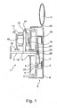
- Fig. 1 is a highly schematic embodiment of a clutch assembly 1 shown.
- This includes a drive shaft 2 driven by an internal combustion engine (not shown), at the free end of which a primary part 3 (rotor, primary side) of a fluid friction clutch 4 (viscous coupling) is fixed in a rotationally fixed manner.
- the fluid friction clutch 4 comprises a hydraulic control valve 5, which serves to adjust the slip of the fluid friction clutch 4.
- the hydraulic control valve 5 By means of the hydraulic control valve 5, the flow rate or the flow volume flow of fluid, in particular an oil between a fluid storage chamber 6 and a working chamber 7 and above the available for transmitting torque in the working chamber 7 amount of fluid can be adjusted.
- a non-illustrated, well-known wiper or pump element is provided, which upon rotation of the primary part 3, the torque transmission fluid from the working chamber 7 back promotes into the fluid storage chamber 6.
- the hydraulic control valve 5 By controlling the hydraulic control valve 5, so to speak, the return flow of fluid into the working chamber 7 and thus the slip of the fluid friction clutch 4 is influenced.
- the fluid is between the primary part 3 (primary side) and a secondary part 8 (secondary side) of the fluid friction clutch and is sheared by rotation of the primary part 3, which rotates with drive shaft speed and thereby transmits the torque to the secondary part 8, which with slip runs after the primary part 3.
- the primary part 3 rotates, driven by the drive shaft 2 relative to the aforementioned secondary part 8 of the fluid friction clutch 4, wherein the secondary part 8 is formed by a housing of the fluid friction clutch 4, which is rotatably supported by a bearing 9 on the drive shaft 2.
- the torque transmission between the primary part 3 and the secondary part 8 takes place, as mentioned above, via the fluid provided in the working chamber 7, wherein the amount of fluid available for torque transmission in the working chamber 7 is controlled in a temperature-controlled manner by means of the hydraulic control valve 5.
- the secondary side 8 (secondary part) of the fluid friction clutch 4 simultaneously forms the (common) output 10, wherein the output 10, a schematically indicated fan 11 is provided.
- the secondary side 8 preferably without slippage, for example, be connected via a propeller shaft with an output. It is also conceivable to provide as output, for example, a pulley, via which then by means of a belt drive an accessory, such as a fan is driven.
- the clutch assembly 1 comprises a formed as an electromagnetic clutch friction disc clutch 12, which is arranged in parallel with the fluid friction clutch 4 in the embodiment shown.
- the clutch assembly 1 comprises a stationary, energizable solenoid assembly 13, which serves both for switching the Reibusionnkupplung12 and for actuating the hydraulic control valve 5.
- the solenoid assembly 13 is rotatably supported relative to the drive shaft 2 via a (further) bearing 14.
- a rotatably connected to the drive shaft 2 rotor 15 of the friction disc clutch 12 is arranged, which rotates at input shaft speed.
- the rotor 15 engages over the electromagnet assembly 13 in the axial direction, so as to achieve an improved coupling (feed) of the magnetic flux.
- armature 18 armature disc
- the armature 18 is in the illustrated embodiment via return means 19 in the form of a return spring fixedly connected to the secondary part 8 of the fluid friction clutch 4.
- the armature 18 may wear a friction disc (not shown) or even as friction for frictional engagement with the rotor 15 when energized Electromagnet assembly 13 serve.
- the armature 18 is applied to the rotor 15 by energizing the solenoid assembly 13, the fluid friction torque transmission mechanism of the fluid friction clutch 4 and the fluid friction clutch 4 is bridged and the secondary side 8 of the fluid friction clutch 4 is given by the friction disc clutch 12 predetermined speed, in a single-stage clutch always the Drive shaft speed, driven.
- the clutch assembly 1 shown is preferably operated such that in a lower output speed range, the friction disc clutch 12 is disengaged.
- the torque is transmitted from the drive shaft 3 to the output 8 exclusively via the fluid friction clutch 4 by the fluid in the working chamber 7 of the fluid friction clutch 4 between the primary part 3 and the secondary part 8.
- the slip of the fluid friction clutch 4 is adjustable over the amount of fluid available for torque transmission in the working chamber 7, which in turn via the hydraulic control valve 5, preferably adjustable in temperature is. At higher cooling demand, the friction disc clutch 12 can be engaged.
- the electromagnet arrangement is supplied with at least a first effective current, whereby the armature 18 is displaced axially against the rotor 15 counter to the spring force of the return means 19 and cooperates frictionally with it.
- the secondary side 8 of the fluid friction clutch 4 is driven at the speed of the rotor 15 or possibly at a lower speed, if the friction disc clutch is designed as a multi-stage clutch.
- the hydraulic control valve 5 comprises an armature 20, which is designed here merely by way of example as a hinged armature and which, in the exemplary embodiment shown, is fixed to the primary part 3 via a spring element 21 (restoring element).
- armature 20 which is designed here merely by way of example as a hinged armature and which, in the exemplary embodiment shown, is fixed to the primary part 3 via a spring element 21 (restoring element).
- a switching valve diskretventil
- a proportional valve control valve 5 different opening cross-sections of a fluid connection 22 (valve connection) and thus the flowing back into the working chamber 7 liquid volume flow.
- the armature 20 is dimensioned or designed so that it (already) can be adjusted at lower currents (currents) of the solenoid assembly 13 as the armature 20 of the friction disc clutch 12.
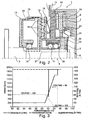
- a further embodiment of a clutch assembly 1 is shown.
- This comprises a common, fixedly arranged electromagnet arrangement 13, whose coil is not shown for reasons of clarity.
- the Electromagnet assembly 13 is axially overlapped by the rotor 15 of the friction disc clutch 12, which comprises an axially adjustable armature 18.
- Evident are a plurality of radially spaced magnetic separations 16 in the rotor 15 and magnetic separations 24 in the armature 18, in a conventional manner the magnetic flux to amplify the magnetic force multiple times between rotor 15 and armature 18 back and forth and to avoid a magnetic short circuit.
- the rotor 15 is rotationally fixed on the drive shaft 2, whereas the drive shaft 2 is rotatable relative to the solenoid assembly 13 via a bearing 14 designed as a rolling bearing.
- the armature 18 of the friction disc clutch 12 is fixed via return means 19 on the secondary part 8 of the fluid friction clutch 4 and thus on the output 10, which carries a fan 11.
- the secondary part 8 is rotatably supported relative to the drive shaft 2 via the (further) bearing 9 designed as a roller bearing, whereas the primary part 3 of the fluid friction clutch 4 is fixed against rotation on the drive shaft 2.
- the fluid friction clutch 4 comprises a hydraulic control valve 5, which is electromagnetically actuated.
- the hydraulic control valve 5 comprises a (control valve) armature 20 for actuating a valve element 25 of the control valve 5, wherein the valve element 25 may be formed depending on the embodiment, also directly from an armature 20 of the fluid friction clutch.
- the valve element 25 is formed in the embodiment shown at the same time as a spring element or return element.
- the volume flow between a fluid storage chamber 6 and a working chamber 7 and thus the slip of the fluid friction clutch can be adjusted.
- the valve element 25 By means of the valve element 25, the opening cross-section of at least one, of which two corresponding fluid connections 22 can be adjusted. In the case of a clocked discrete valve, the fluid volume flow is not set by the free flow cross section but by the ratio of the time component "open" to the time component "closed".
- pumping means known per se for conveying liquid from the working chamber 7 back into the fluid storage chamber 6 are not shown.
- Fig. 2 two magnetic flux circuits can be seen, namely a first magnetic flux circuit 26 and a second magnetic flux circuit 27.
- the first magnetic flux circuit 26 constitutes the main flow circuit for switching the friction disc clutch 12, that is, for actuating the armature 18, whereas the second magnetic flux circuit 27 forms a tributary circuit and for adjusting the control valve 5. Partially cover first and second magnetic circuit 27. In a lower (second) Bestromungs Scheme primarily the second magnetic flux circuit 27 is relevant, since the control valve 5 is designed such that even comparatively low effective second currents sufficient to the armature 18 of the fluid friction clutch 4th to adjust. In this case, the magnetic flux 27 runs from the electromagnet arrangement 13 via rotor 15 and armature 18 through flux-conducting components 28 to an axially spaced working air gap 23 of the viscous coupling 4.
- the materials used for the various components or components of the clutch assembly are selected so that the magnetic flux is selectively guided.
- Fig. 1 Also in the later to be explained embodiment according to the Fig. 4 a and 4 b
- non-ferritic materials such as aluminum, provided with right-rising hatching, whereas the components or components with the left-rising hatchings of ferritic material, eg. B. steel are designed to guide the flow through the latter components targeted.
- the working air gap 23 is bridged and the magnetic flux in the second flow circuit 27 extends back to the electromagnet arrangement here via the drive shaft 2.
- the electromagnet arrangement 13 When the electromagnet arrangement 13 is energized with a first effective current intensity or higher, which is preferably higher than the second effective current intensities, the first magnetic flux circuit 26 comes into play. The generated magnetic force is now sufficient to adjust the armature 18 and engage the friction disc clutch 12, so that in the arrangement according to Fig. 2 the fluid friction clutch is quasi bridged.
- the fluid connections 22 When energized with the effective first current, the fluid connections 22 are substantially closed, so that the fluid friction clutch 4 would actually run with maximum slip, but this essentially does not come to fruition, since the secondary part 8 of the fluid friction clutch 4 is rotated by the friction disc clutch with drive shaft speed ,
- Fig. 3 is a control option an example in Fig. 2 shown clutch assembly 1 shown.
- Plotted is the number of revolutions of the drive shaft from the left vertical axis, the coolant temperature of a radiator to be cooled by means of a fan wheel on the lower horizontal axis and the effective current on the right vertical axis, here expressed in percent PWM (ratio of the time component "current on” to time component). Current off "in one period), with 100% PWM indicating the maximum current.
- the temperature of the coolant is still low. Up to an exemplary selected temperature of 91 ° C, only the fluid friction clutch 6 is operated, with maximum slip. This is achieved by energizing the energization with 60% of the maximum current, here with 60% PWM.
- the fluid volume flow from the liquid storage chamber 6 into the working chamber 7 is minimal, for example, when a proportional control valve, the corresponding fluid connection is closed or minimized. In a discrete valve this is preferably closed. It is now assumed that the temperature of the coolant continues to rise, here initially to 94 ° C, this state changes is counteracted by the electromagnet assembly is now energized with ever lesser or here decreasing second effective current. The current is even reduced from 60% PWM to 0% PWM.
- the fluid connection is further opened in the working chamber and it increases the fluid volume flow from the fluid storage chamber into the working chamber and thus the available torque for transmitting torque in the working chamber, which in turn leads to a reduced slip and thus to an increased speed of the fan.
- This increases from the initially constant 200 revolutions per minute to 1600 revolutions per minute in the example shown.
- the in the Fig. 4 a and 4 b partially shown clutch assembly 1 comprises analogous to the embodiment according to Fig. 2 a Reibusionnkupplung 12 with a translationally adjustable armature 18. This is associated with a fixedly arranged electromagnet assembly 13, the coil, as in the preceding embodiments is not shown for clarity.
- the solenoid assembly 13 is axially overlapped by the rotor 15 of the friction disc clutch. With regard to the structure of the friction disc clutch 12 and in terms of other similarities is to avoid repetition of the embodiment according to Fig. 2 directed.
- the solenoid assembly 13 is not only the armature 18 of the friction disc clutch 12, but also a, here, however, as a rotary armature (rotary armature) formed anchor 20 associated with a fluid friction clutch 4.
- a single magnetic flux circuit 26, which, starting from the single solenoid assembly first passes through the friction disc clutch 12, more precisely, the rotor 15, and the armature 18 and is then closed via the armature 20.
- This, as mentioned as a rotary armature formed anchor 20 is part of the drive shaft 2 and arranged in the drive shaft 2 designed as a hollow shaft.
- the armature 20 of the fluid friction clutch 4 rotates during operation together with the drive shaft 2, but can be rotated relative to the energization of the solenoid assembly 13 relative thereto.
- a valve element 25 of the hydraulic control valve 5 of the fluid-friction disk clutch 4 is rotated relative to at least one fluid connection 22, whereby the amount of fluid in the working chamber 7 is influenced.
- the armature 20 is formed axially elongated and extends beyond the plane of the drawing right end of the drive shaft 2 and is rotatably connected within the fluid storage chamber 6 to the valve element 25.
- a spring element 21 is provided which counteracts the rotational movement of the valve element 25 caused by energization of the electromagnet arrangement 13.
- the solenoid assembly 13 is energized with a first effective current level or higher, which is preferably higher than the second effective current levels, the armature 18 of the friction disc clutch 12 is adjusted, whereby the fluid friction clutch 4 is bridged.
- first effective current level or higher which is preferably higher than the second effective current levels
- second current intensities that is to say in a second current application range
- the position of the armature 20 designed as a rotary armature can be influenced and thus the rotational position of the valve element 25 relative to the fluid connections 22.
- the amount of return of the fluid available for torque transmission into the working chamber 7 is thereby increased and thus the slip of the fluid friction clutch 4 is set. The slip is thus dependent on the angle of rotation of the armature 20 relative to the drive shaft. 2
Landscapes
- Engineering & Computer Science (AREA)
- General Engineering & Computer Science (AREA)
- Mechanical Engineering (AREA)
- Chemical & Material Sciences (AREA)
- Combustion & Propulsion (AREA)
- Physics & Mathematics (AREA)
- Electromagnetism (AREA)
- Hydraulic Clutches, Magnetic Clutches, Fluid Clutches, And Fluid Joints (AREA)
Description
- Die Erfindung betrifft eine Kupplungsanordnung zum Übertragen eines Antriebsdrehmomentes von einer Antriebswelle auf ein Nebenaggregat, insbesondere auf ein Lüfterrad, eines Kraftfahrzeuges, gemäß dem Oberbegriff des Patentanspruches 1, umfassend eine Antriebswelle, einen Abtrieb, sowie eine mittels einer Elektromagnetanordnung schaltbare Reibscheibenkupplung. Ferner betrifft die Erfindung ein Ansteuerverfahren gemäß dem Oberbegriff des Patentanspruchs 14 zum Ansteuern einer derartigen Kupplungsanordnung.
- Grundsätzlich bekannt sind ein- oder mehrstufige Reibscheibenkupplungen zum Antreiben von Nebenaggregaten wie Lüfterrädern. Solche, beispielsweise als elektromagnetisch betätigbare Kupplungen ausgebildete Reibscheibenkupplungen sind beispielsweise in der
EP 0 317 703 A2 , derDE 32 031 43 C2 sowie derDE 42 07 710 A1 beschrieben. Bezüglich des grundsätzlichen Aufbaus, der Wirkungsweise sowie des Einsatzgebietes derartiger Reibscheibenkupplungen wird auf diese Veröffentlichungen verwiesen. Reibscheibenkupplungen haben bei Zuschaltung keinen Schlupf und somit keine Differenzdrehzahl auf der Lagerstelle. Es ist auch allgemein bekannt, dass dies durch die fehlende Abrollung der Wälzkörper zu einem erhöhten Verschleiß und damit zu einer erhöhten Abnutzung bis zum möglichen Ausfall der Lagerstellen im Feldeinsatz führen kann. Insbesondere bei einstufigen Reibscheibenkupplungen ist von Nachteil, dass diese im zugeschalteten (eingekuppelten bzw. verbundenen) Zustand bei hohen Antriebsdrehzahlen oftmals unerwünscht hohe Abtriebsdrehzahlen zur Verfügung stellen und starke Schaltstöße auftreten. - Anstelle der zuvor beschriebenen Reibscheibenkupplungen werden zum Antreiben von Nebenaggregaten von Kraftfahrzeugen so genannte Flüssigkeitsreibungskupplungen, auch Viskokupplung oder Viskositätskupplung genannt, eingesetzt. Bei Viskokupplungen wird eine Drehbewegung von einer Primärseite auf ein Fluid übertragen und von diesem dann auf eine Sekundärseite der Kupplung. Hinsichtlich eines möglichen Aufbaus von Fluidreibungskupplungen wird auf die
US 4,305,491 , dieEP 1 248 007 B1 sowie dieDE 699 11 479 T2 verwiesen. Die meisten im kommerziellen Einsatz befindlichen Flüssigkeitsreibungskupplungen umfassen ein hydraulisches Steuerventil, mit dem der Schlupf der Flüssigkeitsreibungskupplung einstellbar ist. Bei einfachen Ausführungsvarianten wird der Öffnungsquerschnitt des Steuerventils über ein temperaturerfassendes Bimetallelement eingestellt. Daneben sind als Elektromagnetventil ausgebildete Steuerventile bekannt, die den Fluidstrom zwischen einer Speicherkammer und einer Arbeitskammer und damit den Schlupf der Flüssigkeitsreibungskupplung steuern. Grundsätzlich ist es bekannt, die hydraulischen Steuerventile als Proportionalventile auszubilden oder alternativ als getaktet betriebene Diskretventile, bei denen die Durchflussmenge abhängig von dem Verhältnis des geöffneten Zeitanteils zu dem geschlossenen Zeitanteil des Ankers ist. - Im Gegensatz zu einstufigen Reibscheibenkupplungen haben Flüssigkeitsreibungskupplungen ein träges Ansprechverhalten und sind mit hohen Schlupfwerten behaftet. Ausgehend von dem vorgenannten Stand der Technik, liegt der Erfindung die Aufgabe zugrunde eine alternative Kupplungsanordnung anzugeben, die sich durch einen geringeren Verschleiß der Reibscheibenkupplung auszeichnet. Insbesondere soll die Kupplungsanordnung mit möglichst wenig funktionalen Komponenten auskommen. Insbesondere soll sich die Kupplungsanordnung durch eine komfortable Ansteuerbarkeit auszeichnen. Bevorzugt soll eine variable Drehzahleinstellung über einen großen Bereich gewährleistet werden sowie gute Dämpfungseigenschaften und ein schnelles Ansprechverhalten, bevorzugt bei voller Durchschaltmöglichkeit. Ferner besteht die Aufgabe darin, ein vereinfachtes Ansteuerverfahren für eine derartige Kupplungsanordnung anzugeben.
- Aus der
JP 54 111027 A - Zum weiteren Stand der Technik wird die
DE 89 08 357 U1 genannt, die eine Flüssigkeitsreibungskupplung zeigt. DieWO 2004/007923 A1 beschreibt eine Vorrichtung zum Antreiben einer Kühlmittelpumpe, umfassend eine Flüssigkeitsreibungskupplung sowie eine als Elektromagnetkupplung ausgebildete Schaltkupplung, die parallel zur Flüssigkeitsreibungskupplung in den Antriebsstrang schaltbar ist. - Diese Aufgabe wird mit einer Kupplungsanordnung mit den Merkmalen des Patentanspruchs 1 gelöst, insbesondere dadurch, dass die Kupplungsanordnung zusätzlich zu der Reibscheibenkupplung zur Drehmomentübertragung von der Antriebswelle auf den Abtrieb einer Flüssigkeitsreibungskupplung umfasst, deren hydraulisches Steuerventil (Elektromagnetventil) zur Einstellung des Schlupfes mittels der Elektromagnetanordnung der Reibscheibenkupplung ansteuerbar ist.
- Hinsichtlich des Verfahrens wird die Aufgabe mit den Merkmalen des Anspruchs 14 gelöst.
- Weitere Vorteile, Merkmale und Einzelheiten der Erfindung sind in den Unteransprüchen angegeben. In den Rahmen der Erfindung fallen sämtliche Kombinationen aus zumindest zwei von in der Beschreibung, den Ansprüchen und/oder den Figuren offenbarten Merkmalen. Zur Vermeidung von Wiederholungen sollen vorrichtungsgemäß offenbarte Merkmale auch als verfahrensgemäß offenbart gelten und beanspruchbar sein. Ebenso sollen verfahrensgemäß offenbarte Merkmale auch als vorrichtungsgemäß offenbart gelten und beanspruchbar sein.
- Der Erfindung liegt der Gedanke zugrunde, bei einer eine elektromagnetisch aktuierbare Reibscheibenkupplung sowie eine elektromagnetisch aktuierbare Flüssigkeitsreibungskupplung (Viskokupplung) umfassenden Kupplungsanordnung der Reibscheibenkupplung und der Flüssigkeitsreibungskupplung eine gemeinsame Elektromagnetanordnung zuzuordnen, mit der sowohl die Reibscheibenkupplung schaltbar, d.h. ein- oder auskuppelbar ist, als auch das hydraulische Steuerventil der Flüssigkeitsreibungskupplung verstellbar ist. Anders ausgedrückt ist bei der erfindungsgemäßen Kupplungsanordnung eine Elektromagnetanordnung derart ausgebildet und angeordnet, dass diese, vorzugsweise in Abhängigkeit von deren effektiver Bestromung die Reibscheibenkupplung schaltet sowie das hydraulische Steuerventil der Flüssigkeitsreibungskupplung ansteuert bzw. verstellt, um somit die zur Drehmomentübertragung in der Flüssigkeitsreibungskupplung zwischen Primär- und Sekundärseite der Flüssigkeitsreibungskupplung zur Verfügung stehende Flüssigkeitsmenge insbesondere Ölmenge einzustellen. Noch anders ausgedrückt ist eine gemeinsame Elektromagnetanordnung für die Reibscheibenkupplung und die Flüssigkeitsreibungskupplung vorgesehen, mit der sowohl ein Anker der Reibscheibenkupplung als auch ein dem Steuerventil der Flüssigkeitsreibungskupplung zugeordneter Anker zur Einstellung des Schlupfes der Flüssigkeitsreibungskupplung betätigbar ist. Der Elektromagnetanordnung können dabei gemäß einer ersten Ausführungsform zwei magnetische Flusskreise zugeordnet werden, bzw. werden von dieser erzeugt, wobei ein erster Flusskreis zur Betätigung des vorzugsweise als Reibscheibe ausgebildeten oder eine Reibscheibe tragenden Ankers der Reibscheibenkupplung dient und der zweite magnetische Flusskreis zur Verstellung des Ankers des elektromagnetisch betätigbaren hydraulischen Steuerventils zur Einstellung des Schlupfes der Flüssigkeitsreibungskupplung. Durch das Vorsehen einer gemeinsamen Elektromagnetanordnung kann auf eine separate Elektromagnetanordnung zur separaten Schaltung bzw. Ansteuerung der Reibscheibenkupplung und zur Schaltung bzw. Ansteuerung der Flüssigkeitsreibungskupplung verzichtet werden. Alternativ ist eine Ausführung mit einem einzigen Magnetkreis realisierbar, insbesondere dann, wenn zum Verstellen des Hydraulikventils der Viskosekupplung ein Drehanker vorgesehen wird, wobei bei einer solchen Ausführung der Magnetkreis vorzugsweise zunächst durch den Anker und den Rotor der Reibscheibenkupplung und dann durch das, insbesondere als Drehanker ausgebildeten, Anker der Fluidreibungskupplung verläuft. Selbstverständlich ist es auch möglich, anders ausgebildete Anker, wie Schiebeanker mit einem einzigen Flusskreis anzusteuern. Im Falle der Realisierung eines einzigen Flusskreises, muss dieser also die Luftspalte bzw. Arbeitsspalte beider Anker (Reibscheibenkupplungsanker sowie Viskokupplungsanker) überbrücken.
- Neben der vorgenannten Doppelfunktion der, vorzugsweise einzigen, Elektromagnetanordnung der erfindungsgemäßen Kupplungsanordnung, hat diese weitere Vorteile. So umfasst die erfindungsgemäße Kupplungsanordnung, wie vorerwähnt, neben einer ein- oder mehrstufig ausgebildeten elektromagnetisch ansteuerbaren Reibscheibenkupplung in einem gemeinsamen Antriebsstrang für eine Nebenaggregat eine Flüssigkeitsreibungskupplung, um das Drehmoment von der Antriebswelle auf das Nebenaggregat, insbesondere ein Lüfterrad eines Kraftfahrzeugs, vorzugsweise zur Kühlung des Verbrennungsmotors zu übertragen. Die Erfindung nimmt also bewusst einen auf den ersten Blick komplexeren und kostenintensiveren Aufbau einer Kupplungsanordnung in Kauf, um dann überraschend die Vorteile einer an sich bekannten Reibscheibenkupplung einerseits und einer an sich bekannten Flüssigkeitsreibungskupplung andererseits miteinander zu kombinieren, wobei der zunächst komplexe anmutende Aufbau dadurch erfindungsgemäß, wesentlich vereinfacht und kostengünstiger ausgeführt wird, dass eine gemeinsame Elektromagnetkupplung zur Betätigung Reibscheibenkupplung und der Flüssigkeitsreibungskupplung vorgesehen ist. Durch die Kombination der Reibscheibenkupplungstechnologie mit der Flüssigkeitsreibungstechnologie in einer gemeinsamen Kupplungsanordnung kann ein gedämpftes (sanftes) Zuschalten der Reibscheibenkupplung realisiert werden, woraus ein geringerer Verschleiß der Reibscheibenkupplung insbesondere der Reibscheibe der Reibscheibenkupplung resultiert. Ferner resultiert aus der Kombination von Reibscheibenkupplung und Flüssigkeitsreibungskupplung eine geringere Belastung eines fakultativ am Abtrieb vorgesehenen Riementriebs. Darüber hinaus kann aufgrund einer möglichen Abriegelung der Energieverbrauch bei hohen Motordrehzahlen reduziert werden. Auch wird aufgrund der Kombination eine Dämpfung von Torsionsschwingungen erreicht, wodurch die erfindungemäße Kupplungsanordnung kurbelwellentauglich wird. Ganz besonders bevorzugt ist die Kupplungsanordnung derart ausgelegt, dass in einem unteren Drehzahlbereich, vorzugsweise zwischen etwa 10% und 85% der maximalen Drehzahl das Nebenaggregat ausschließlich über die Flüssigkeitsreibungskupplung betrieben wird, wobei das übertragende Drehmoment, durch eine entsprechende Ansteuerung des hydraulischen Steuerventils mit der gemeinsamen Elektromagnetanordnung modulierbar ist. Die Reibscheibenkupplung kann dann zugeschaltet werden, wenn ein hoher Kühlbedarf besteht, wobei sich die Reibscheibenkupplung durch eine schnelle Zuschaltbarkeit auszeichnet.
- In Weiterbildung der Erfindung ist mit Vorteil vorgesehen, dass die Flüssigkeitsreibungskupplung und die Reibscheibenkupplung parallel angeordnet sind, also derart, dass der Kraftfluss bei Entkupplung (Auskupplung) einer der beiden Kupplungen, insbesondere der Reibscheibenkupplung von der Antriebswelle zum Abtrieb über die andere Kupplung, insbesondere die Flüssigkeitsreibungskupplung verläuft. Wird die Reibscheibenkupplung vom Abtrieb entkuppelt, kann also das Drehmoment bei bevorzugt paralleler Anordnung ausschließlich über die Flüssigkeitsreibungskupplung von der Antriebswelle zum Abtrieb übertragen werden. Wie eingangs erwähnt erfolgt die Drehmomentübertragung vorzugsweise ausschließlich über die Flüssigkeitsreibungskupplung in einem unteren Last- bzw. Drehzahlbereich, insbesondere dann, wenn nicht die maximale Kühllast angefordert wird.
- Ganz besonders bevorzugt ist eine vorteilhafte Ausgestaltung der Erfindung nach welcher die Flüssigkeitsreibungskupplung mittels der Reibscheibenkupplung überbrückbar ist. Mit anderen Worten sind die Flüssigkeitsreibungskupplung und die Reibscheibenkupplung vorzugsweise derart angeordnet bzw. wirdken derart miteinander zusammen, dass bei eingekuppelter Reibscheibenkupplung eine schlupffreie Drehmomentübertragung von der Antriebswelle auf den Abtrieb möglich ist. Hierdurch kann schlupffrei das Drehmoment übertragen werden, was insbesondere bei hohen Kühllasten von Vorteil ist.
- Ganz besonders zweckmäßig ist es, wenn der Abtrieb der Kupplungsanordnung von der Sekundärseite (Abtriebsseite) der Flüssigkeitsreibungskupplung gebildet ist, oder wenn der Abtrieb der Kupplungsanordnung, vorzugsweise schlupffrei, insbesondere über eine Gelenkwelle, mit der Sekundärseite der Flüssigkeitsreibungskupplung gekoppelt, d.h. wirkverbunden ist. Bevorzugt ist die Sekundärseite der Flüssigkeitsreibungskupplung relativ drehbar zur Antriebswelle gelagert, wobei bei ausgekuppelter Reibscheibenkupplung das Drehmoment mittels der Flüssigkeitsreibungskupplung bevorzugt ausschließlich über die Flüssigkeit, insbesondere ein Öl, in der Flüssigkeitsreibungskupplung von der Primärseite auf die Sekundärseite übertragen wird, wobei wie eingangs erwähnt, die zur Drehmomentübertragung zur Verfügung stehende Flüssigkeitsmenge zwischen Sekundärseite und Primärseite in an sich bekannter Weise über das hydraulische Steuerventil einstellbar ist, wobei jedoch erfindungsgemäß das hydraulische Steuerventil mittels der gemeinsamen Elektromagnetanordnung ansteuerbar ist. Die Primärseite der Flüssigkeitsreibungskupplung ist bevorzugt dauerhaft fest mit der Antriebswelle verbunden. Ganz besonderes bevorzugt ist der Rotor der Flüssigkeitsreibungskupplung am freien Ende der Antriebswelle festgelegt.
- Ganz besonders bevorzugt ist es, wenn die Sekundärseite der Flüssigkeitsreibungskupplung über die Reibscheibenkupplung reibschlüssig drehmomentübertragend mit der Antriebswelle verbindbar ist. Bevorzugt ist der Sekundärseite der Flüssigkeitsreibungskupplung hierzu ein Rotor der Reibscheibenkupplung zugeordnet, wobei die Sekundärseite der Flüssigkeitsreibungskupplung, insbesondere über einen axial verstellbaren Anker reibschlüssig mit diesem Rotor verbindbar ist. In diesem Fall wird, insbesondere für den Fall der Ausbildung der Reibscheibenkupplung als einstufige Kupplung der Flüssigreibungsdrehmornentübertragungsmechanismus der Flüssigkeitsreibscheibenkupplung überbrückt, da die Sekundärseite der Flüssigkeitsreibungskupplung unmittelbar von der Reibscheibenkupplung angetrieben wird, welche bevorzugt, insbesondere im Falle der Ausbildung der Reibscheibenkupplung als einstufige Kupplung, mit Antriebswellendrehzahl dreht.
- Ganz besonders bevorzugt ist eine Ausführungsvariante, bei welcher der Rotor der Reibscheibenkupplung axial zwischen der gemeinsamen Elektromagnetanordnung und der Flüssigkeitsreibungskupplung insbesondere der Sekundärseite der Flüssigkeitsreibungskupplung angeordnet ist, wobei der erste magnetische Flusskreis von der Elektromagnetanordnung in den Rotor eingeleitet wird und (bei ausreichender effektiver .Bestromung der Elektromagnetanordnung) über einen vorzugsweise mit Luft gefüllten Spalt (Arbeitsluftspalt) zum mit der Sekundärseite der Flüssigkeitsreibungskupplung verbundenen Anker geführt wird.. Bevorzugt sind hier zumindestens zwei in radialer Richtung beabstandete Abschnitte des Rotors über eine magnetische Trennung miteinander verbunden, bzw. magnetisch getrennt, um einen magnetischen Kurzschluss zu vermeiden.
- Besonders bevorzugt ist in Weiterbildung der Erfindung mit Vorteil vorgesehen, dass der vorerwähnte Anker der Reibscheibenkupplung über Rückstellmittel, insbesondere eine Rückstellfeder, an der Sekundärseite der Flüssigkeitsreibungskupplung festgelegt ist. Besonders zweckmäßig ist es, wenn es sich bei dem Rückstellmittel um eine den Anker von dem Rotor in Richtung Sekundärseite der Flüssigkeitsreibungskupplung wegziehende, d.h. entkuppelnde, Feder handelt, wobei es selbstverständlich auch möglich ist bei einer alternativen Ausführungsvariante die Feder als Druckfeder auszubilden, um die Reibscheibenkupplung in diesem Fall im nicht bestromten Zustand geschlossen, d.h. eingekuppelt, zu halten. Die Reibscheibenkupplung kann also sowohl als im bestromten Zustand eingekuppelte als auch alternativ im bestromten Zustand ausgekuppelte, d.h. als ausfallsichere, Kupplung realisiert werden.
- Im Hinblick auf die Ausführung des Ankers der Reibscheibenkupplung gibt es unterschiedliche Möglichkeiten. Gemäß einer ersten, bevorzugten Alternative bildet der Anker gleichzeitig unmittelbar eine Reibscheibe zum reibschlüssigen Zusammenwirken mit dem Rotor. Bei einer alternativen Ausgestaltungsvariante trägt der Anker eine Reibscheibe, welche mittels des Ankers axial verstellbar ist, um reibschlüssig mit dem Rotor der Reibscheibenkupplung zusammenzuwirken.
- Besonders zweckmäßig ist es, wenn die Reibscheibenkupplung als einfache einstufige Kupplung ausgebildet ist, also als eine Kupplung, die entweder das volle Drehmoment oder kein Drehmoment überträgt, wobei es selbstverständlich auch möglich ist, eine zwei- drei- oder noch mehrstufige Kupplung als Reibscheibenkupplung vorzusehen, beispielsweise eine die in der
DE 20 2007 004 786 U1 beschriebene Reibscheibenkupplung, wobei es besonders zweckmäßig ist, wenn im Falle der Ausbildung der Kupplung als mehrstufige Kupplung Wirbelstrommittel zum Erzeugen eines Wirbelstroms zum Zwecke des Mitschleppens bzw. eines Kupplungsteiles, d.h. zum Erzeugen eines Schlupfes vorgesehen sind. - Um die Reibscheibenkupplung und die Flüssigkeitsreibungskupplung optimal, d.h. vorzugsweise separat voneinander mittels der Elektromagnetanordnung ansteuern zu können, ist in Weiterbildung der Erfindung vorgesehen, dass der Anker der Reibscheibenkupplung durch Bestromen der Elektromagnetanordnung mit einer ersten Stromstärke schaltbar ist, dass also bei Über- oder Unterschreiten der ersten effektiven Stromstärke (Schwellwert) die Reibscheibenkupplung geschaltet wird und dass durch Bestromen der gemeinsamen Elektromagnetanordnung mit einer von der ersten Stromstärke unterschiedlichen zweiten effektiven Stromstärke der Anker des hydraulischen Steuerventils der Flüssigkeitsreibungskupplung zur Einstellung des Schlupfes verstellt wird. Besonders bevorzugt ist es, wenn die Durchflussmenge des Steuerventils gestuft oder stufenlos einstellbar ist, so dass durch eine entsprechende Bestromung der Elektromagnetanordnung mehr als zwei unterschiedliche Schlupfwerte der Flüssigkeitsreibungskupplung realisierbar sind. Grundsätzlich ist es denkbar, dass die zweite effektive Stromstärke zur Einstellung einer gewünschten Durchflussmenge durch das Steuerventil und damit zur Einstellung einer zur Drehmomentübertragung zur Verfügung stehenden Flüssigkeitsmenge größer ist als die erste effektive Stromstärke. Besonders bevorzugt ist jedoch eine Ausführungsvariante, bei der die erste Stromstärke, insbesondere deutlich, größer ist als die mindestens eine zweite effektive Stromstärke, um somit durch Bestromung der Elektromagnetanordnung in einem ersten, insbesondere höheren Bestromungsbereich (Stromstärkenbereich) die Reibscheibenkupplung zu schalten und durch Bestromung in einem zweiten, vorzugsweise niedrigeren Bestromungsbereich (Stromstärkenbereich) die Flüssigkeitsreibungskupplung, genauer deren hydraulisches Steuerventil einzustellen, um damit unterschiedliche Durchflussmengen und damit Schlupfwerte einstellen zu können.
- Unter einer effektiven Stromstärke wird dabei die flussrelevante Stromstärke verstanden, also die Stromstärke der Elektromagnetanordnungsbestromung, die zur Erzeugung des magnetischen Feldes zur Verfügung steht bzw. zu der das erzeugte magnetische Feld bzw. der erzeugte magnetische Fluss in einem funktionalen Zusammenhang steht. Wird die Elektromagnetanordnung beispielsweise mit konstanten Gleichströmen bestromt, so ist unter der effektiven Stromstärke diese jeweils konstante Stromstärke (nicht gepulste Ströme) zu verstehen. Wird die Elektromagnetanordnung beispielsweise mit einem PWM-Signal bestromt, so ist unter der effektiven Stromstärke die resultierende bzw. in einem bestimmten Zeitintervall, insbesondere in einer Periode, mittlere Stromstärke zu verstehen. Wie zuvor erwähnt ist es besonders bevorzugt, wenn die Flüssigkeitsreibungskupplung nicht ausschließlich zwei Schaltzustände kennt bzw. aufweist, sondern wenn die Durchflussmenge durch die Flüssigkeitsreibungskupplung in mehreren Stufen oder kontinuierlich einstellbar ist, um eine besonders gute Modulation des Schlupfes der Flüssigkeitsreibungskupplung zu ermöglichen. Dies kann dadurch realisiert werden, dass die Elektromagnetanordnung mit unterschiedlichen zweiten effektiven Stromstärken aus einem zweiten Bestromungsbereich bestrombar ist, welcher vorzugsweise niedriger ist als ein erster Bestromungsbereich, in dem die erste effektive Stromstärke (Schwellwert) zur Betätigung der Reibscheibenkupplung angeordnet ist. Die unterschiedlichen effektiven Stromstärken können durch Bestromen mit unterschiedlichen PWM-Tastverhältnissen eingestellt werden oder durch unterschiedlich hohe Konstantströme (nicht gepulste Ströme). Unter dem PWM-Tastverhältnis wird das Verhältnis in einer Periode zwischen dem Zeitanteil in dem der Strom eingeschaltet ist zu dem Zeitanteil verstanden in dem der Strom ausgeschaltet ist. Beträgt die PWM-Frequenz z. B. 1 Hz, beträgt die zu berücksichtigende Zeit (Periodendauer) 1 s; 60 % PWM bedeutet dann 0,6 s Strom ein und 0,4 s Strom aus. Beträgt die Frequenz 5 Hz, beträgt die zu betrachtende Zeit (Periodendauer) 0,2 s; 60 % PWM bedeuten hier 0,12 s Strom ein und 0,08 s Strom aus. Die effektive Stromstärke ist bei beiden vorgenannten Beispielen gleich, lediglich die Zeitbasis, d. h. die Periodendauer (Zeit zwischen zwei ansteigenden Pulsflanken) ist unterschiedlich. Die vorerwähnten Bestromungweisen bieten sich beispielsweise an, wenn das hydraulische Steuerventil als so genanntes Proportionalventil ausgebildet ist, bei welchem die Durchflussmenge über den einstellbaren Durchflussquerschnitt eingestellt wird. Für den Fall, dass das Proportionalventil PWM - bestromt wird, sollte eine vergleichsweise hohe PWM-Frequenz gewählt werden, z. B. 400 Hz. Im Falle des Einsatzes eines so genannten Diskretventils als hydraulisches Steuerventil, also eines getaktet betriebenen (schnellalternierend öffnenden und schließenden) Ventils kann die Bestromung alternativ mittels eines an- und abzuschaltenden Konstantstromes (nicht gepulst) oder mittels eines PWM-Signals (gepulster Strom) erfolgen, wobei die PWM-Frequenz bevorzugt gering ist, z.B. 1 Hz.
- Wie zuvor erwähnt ist es denkbar, dass mehrere effektive (unterschiedliche) zweite Stromstärken zur Einstellung unterschiedlicher Durchflussmengen im Steuerventil höher sind als eine erste effektive Stromstärke, insbesondere ein Schwellwert zum Schalten der Reibscheibenkupplung. Bevorzugt ist jedoch eine Ausführungsvariante, bei der die erste effektive Stromstärke, ab deren Erreichen die Reibscheibenkupplung geöffnet oder geschlossen wird, größer ist als die vorerwähnten zweiten Stromstärken. Anders ausgedrückt sind die effektiven zweiten effektiven Stromstärken zum Einstellen unterschiedlicher Durchflussmengen im hydraulischen Steuerventil in einem zweiten Bestromungsbereich angesiedelt angeordnet und die erste effektive Stromstärke bei deren Überoder Unterschreiten eine Betätigung des Ankers der Reibschreibenkupplung resultiert bzw. ein Schalten der Reibscheibenkupplung resultiert in einem ersten Bestromungsbereich, wobei es besonders bevorzugt ist, wenn der erste Bestromungsbereich (Stromstärkenbereich) höher ist als der zweite Bestromungsbereich.
- Ganz besonders bevorzugt ist eine Ausführungsvariante, bei der die Reibscheibenkupplung bei Erreichen und Überschreiten der ersten effektiven Stromstärke geschaltet wird und bei zunehmender effektiver zweiter Stromstärke oder zunehmendem Tastverhältnis der Elektromagnetanordnungsbestromung der Schlupf der Flüssigkeitsreibungskupplung zunimmt. Anders ausgedrückt ist der Schlupf umso höher, je höher die zweite effektive Stromstärke ist. Bei dieser Variante handelt es sich um eine so genannte ausfallsichere Ausführungsform (fail-safe), da bei fehlender Bestromung die maximal mit der Viskokupplung mögliche Drehzahl (geringster Schlupf) übertragen wird. Alternativ kann das Steuerventil so ausgebildet und angeordnet werden, dass der Schlupf umso größer wird, je geringer die zweite effektive Stromstärke ist.
- Besonders zweckmäßig ist es, wenn das hydraulische Steuerventil der Fluidreibungskupplung bei Bestromung der Elektromagnetanordnung mit (mindestens) der ersten effektiven Stromstärke geschlossen ist.
- Im Hinblick auf die Erzeugung der ersten und zweiten effektiven Stromstärke gibt es, wie zuvor erwähnt, unterschiedliche Möglichkeiten. Ganz besonders bevorzugt ist es, die unterschiedlichen effektiven Stromstärken mit Hilfe unterschiedlicher PWM-Signale bzw. mit unterschiedlichen Tastverhältnissen durch den Einsatz von PWM-Mitteln zu erzeugen. Alternativ können Stromkreisregelmittel vorgesehen sein, mit denen mehr oder weniger konstante, d. h. nicht gepulste, bzw. nicht modulierte Ströme bereitstellbar sind.
- Im Hinblick auf die Ausbildung des Ankers des hydraulischen Steuerventils, welcher durch Bestromen der Elektromagnetanordnung mit mindestens einer zweiten effektiven Stromstärke verstellbar ist, gibt es unterschiedliche Möglichkeiten. So ist es denkbar als Anker einen translatorisch verstellbaren Anker vorzusehen, oder einen verschwenkbaren Anker (Klappanker) Auch ist es denkbar einen rotatorisch verstellbaren Anker (Rotationsanker) vorzusehen, welcher noch weiter bevorzugt in der Antriebswelle angeordnet ist.
- Die Erfindung führt auch auf ein Verfahren zum Ansteuern einer erfindungsgemäßen, zuvor im Detail erläuterten Kupplungsanordnung. Das Verfahren zeichnet sich dadurch aus, dass diese Kupplungsanordnung zusätzlich zu der Reibscheibenkupplung zur Drehmomentübertragung von der Antriebswelle auf den Abtrieb eine Flüssigkeitsreibungskupplung umfasst, deren hydraulisches Steuerventil zur Einstellung des Schlupfes mittels der (gemeinsamen) Elektromagnetanordnung für die Reibscheibenkupplung und die Flüssigkeitsreibungskupplung angesteuert wird. Bevorzugt erfolgt die Ansteuerung, wie zuvor im Zusammenhang mit der Beschreibung der Vorrichtung bzw. der Anordnung erläutert durch Bestromen mit unterschiedlichen effektiven Stromstärken, insbesondere um durch Über- oder Unterschreiten einer ersten effektiven Stromstärke die Reibscheibenkupplung zu schalten und durch Bestromen mit zweiten effektiven Stromstärken oder durch Bestromen mit unterschiedlichen Tastverhältnissen die Durchflussmenge durch das hydraulische Steuerventil der Flüssigkeitsreibungskupplung einzustellen, um somit die zur Drehmomentübertragung zur Verfügung stehende Flüssigkeitsmenge zu regulieren um schlussendlich hierdurch den Schlupf der Flüssigkeitsreibungskupplung zu beeinflussen.
- Weitere Vorteile, Merkmale und Einzelheiten der Erfindung ergeben sich aus der nachfolgenden Beschreibung bevorzugter Ausführungsbeispiele sowie anhand der Zeichnungen.
- Diese zeigen in:
- Fig. 1:
- eine schematische Darstellung einer Kupplungsanordnung, die neben einer als Elektromagnetkupplung ausgebildeten, einstufigen (alternativ mehrstufigen) Reibscheibenkupplung eine variable, ein elektromagnetisch betätigbares Steuerventil umfassende Flüssigkeitsreibungskupplung zur Drehmomentübertragung des Drehmoments von einer Antriebswelle auf ein Nebenaggregat, hier ein Lüfterrad einer Verbrennungsmotorkühlung umfasst, wobei die Reibscheibenkupplung und die Flüssigkeitsreibungskupplung parallel angeordnet sind,
- Fig. 2:
- eine ausschnittsweise Darstellung einer möglichen Ausführungsvariante einer Kupplungsanordnung, wobei aus der Darstellung zwei magnetische Flusskreise ersichtlich sind, wobei ein erster Flusskreis zur Betätigung eines Ankers einer Reibscheibenkupplung und ein zweiter Flusskreis zur Betätigung eines Ankers eines hydraulischen Steuerventils einer Flüssigkeitsreibungskupplung umfasst,
- Fig. 3:
- ein Diagramm für eine mögliche Ansteuerung einer Kupplungsanordnung mit einer gemeinsamen Elektromagnetanordnung für die Reibscheibenkupplung und die Flüssigkeitsreibungskupplung,
- Fig. 4 a:
- eine ausschnittsweise Darstellung einer möglichen Ausführungsvariante einer Kupplungsanordnung, wobei als Anker zur Betätigung des hydraulischen Steuerventils der Flüssigkeitsreibungskupplung ein Drehanker (Rotationsanker) vorgesehen ist, der gemäß einer bevorzugten Ausführung in der Antriebswelle angeordnet ist, und
- Fig. 4 b:
- eine Schnittansicht entlang der Schnittlinie A-A gemäß
Fig. 4a . - In den Figuren sind gleiche Elemente und Elemente mit der gleichen Funktion mit den gleichen Bezugszeichen gekennzeichnet.
- In
Fig. 1 ist stark schematisiert ein Ausführungsbeispiel einer Kupplungsanordnung 1 gezeigt. Diese umfasst eine von einem nicht dargestellten Verbrennungsmotor angetriebene Antriebswelle 2, an deren freien Ende ein Primärteil 3 (Rotor, Primärseite) einer Flüssigkeitsreibungskupplung 4 (Viskokupplung) drehfest festgelegt ist. Die Flüssigkeitsreibungskupplung 4 umfasst ein hydraulisches Steuerventil 5, welches zur Einstellung des Schlupfes der Flüssigkeitsreibungskupplung 4 dient. Mithilfe des hydraulischen Steuerventils 5 kann die Durchflussmenge bzw. der Durchflussvolumenstrom an Fluid, insbesondere einem Öl zwischen einer Fluidspeicherkammer 6 und einer Arbeitskammer 7 und darüber die zur Drehmomentübertragung in der Arbeitskammer 7 zur Verfügung stehende Menge an Fluid eingestellt werden. Zwischen der Arbeitskammer 7 und dem Fluidspeicher 6 ist ein nicht dargestelltes, allgemein bekanntes Wischer- oder Pumpenelement vorgesehen, welches bei Rotation des Primärteils 3 das Drehmomentübertragungsfluid aus der Arbeitskammer 7 zurück in die Fluidspeicherkammer 6 fördert. Durch Ansteuerung des hydraulischen Steuerventils 5 wird also quasi der Rückstrom an Fluid in die Arbeitskammer 7 und damit der Schlupf der Flüssigkeitsreibungskupplung 4 beeinflusst. - In der Arbeitskammer 7 befindet sich das Fluid zwischen dem Primärteil 3 (Primärseite) und einem Sekundärteil 8 (Sekundärseite) der Flüssigkeitsreibungskupplung und wird durch Rotation des Primärteils 3, welches mit Antriebswellendrehzahl dreht geschert und überträgt dadurch das Drehmoment auf das Sekundärteil 8, welches mit Schlupf dem Primärteil 3 nachläuft.
- Das Primärteil 3 rotiert, angetrieben von der Antriebswelle 2 relativ zu dem vorerwähnten Sekundärteil 8 der Flüssigkeitsreibungskupplung 4, wobei das Sekundärteil 8 von einem Gehäuse der Flüssigkeitsreibungskupplung 4 gebildet ist, welches über ein Lager 9 drehbar auf der Antriebswelle 2 gelagert ist. Die Drehmomentübertragung zwischen dem Primärteil 3 und dem Sekundärteil 8 erfolgt, wie zuvor erwähnt über die in der Arbeitskammer 7 vorgesehene Flüssigkeit, wobei die zur Drehmomentübertragung zur Verfügung stehende Flüssigkeitsmenge in der Arbeitskammer 7 temperaturabhängig gesteuert mithilfe des hydraulischen Steuerventils 5 einstellbar ist.
- In dem gezeigten Ausführungsbeispiel bildet die Sekundärseite 8 (Sekundärteil) der Flüssigkeitsreibungskupplung 4 gleichzeitig den (gemeinsamen) Abtrieb 10, wobei am Abtrieb 10 ein schematisch angedeutetes Lüfterrad 11 vorgesehen ist. Anstelle des Vorsehens einer Lüfterrads 11 kann die Sekundärseite 8, vorzugsweise schlupffrei, beispielsweise über eine Gelenkwelle mit einem Abtrieb verbunden sein. Auch ist es denkbar als Abtrieb beispielsweise eine Riemenscheibe vorzusehen, über die dann mittels eines Riementriebes ein Nebenaggregat, beispielsweise ein Lüfterrad antreibbar ist.
- Ferner umfasst die Kupplungsanordnung 1 eine als Elektromagnetkupplung ausgebildete Reibscheibenkupplung 12, welche in dem gezeigten Ausführungsbeispiel mit der Flüssigkeitsreibungskupplung 4 parallel angeordnet ist. Die Kupplungsanordnung 1 umfasst eine stationäre, bestrombare Elektromagnetanordnung 13, welche sowohl zum Schalten der Reibscheibenkupplung12 als auch zum Betätigen des hydraulischen Steuerventils 5 dient. Die Elektromagnetanordnung 13 ist relativ zu der Antriebswelle 2 über ein (weiteres) Lager 14 drehbar gelagert.
- Axial zwischen der Elektromagnetanordnung 13 und dem Sekundärteil 8 der Flüssigkeitsreibungskupplung 4 ist ein drehfest mit der Antriebswelle 2 verbundener Rotor 15 der Reibscheibenkupplung 12 angeordnet, der mit Antriebswellendrehzahl dreht. In dem gezeigten Ausführungsbeispiel übergreift der Rotor 15 die Elektromagnetanordnung 13 in axialer Richtung, um somit eine verbesserte Einkupplung (Einspeisung) des magnetischen Flusses zu erreichen. Zu erkennen ist eine schematisch dargestellte magnetische Trennung 16 in Form eines Ringes an einem nicht magnetischen Material, welcher den magnetischen Fluss über einen ggf. mit Öl gefüllten Arbeitsluftspalt 17 in einen Anker 18 (Ankerscheibe) der Reibscheibenkupplung 12 zwingt. Der Anker 18 ist in dem gezeigten Ausführungsbeispiel über Rückstellmittel 19 in Form einer Rückstellfeder fest verbunden mit dem Sekundärteil 8 der Flüssigkeitsreibungskupplung 4. Der Anker 18 kann eine Reibscheibe tragen (nicht dargestellt) oder selbst als Reibscheibe zum reibschlüssigen Zusammenwirken mit dem Rotor 15 bei Bestromung der Elektromagnetanordnung 13 dienen. Wenn der Anker 18 durch Bestromung der Elektromagnetanordnung 13 am Rotor 15 anliegt, ist der Flüssigkeitsreibungsdrehmoment-Übertragungsmechanismus der Flüssigkeitsreibungskupplung 4 bzw. ist die Flüssigkeitsreibungskupplung 4 überbrückt und die Sekundärseite 8 der Flüssigkeitsreibungskupplung 4 wird von der Reibscheibenkupplung 12 vorgegebenen Drehzahl, bei einer einstufigen Kupplung immer der Antriebswellendrehzahl, angetrieben.
- Die gezeigte Kupplungsanordnung 1 wird bevorzugt derart betrieben, dass in einem unteren Abtriebsdrehzahlbereich die Reibscheibenkupplung 12 ausgekuppelt ist. In diesem Zustand erfolgt die Drehmomentübertragung von der Antriebswelle 3 auf den Abtrieb 8 ausschließlich über die Flüssigkeitsreibungskupplung 4 durch Scherung des Fluids in der Arbeitskammer 7 der Flüssigkeitsreibungskupplung 4 zwischen Primärteil 3 und Sekundärteil 8. Der Schlupf der Flüssigkeitsreibungskupplung 4 ist einstellbar über die zur Drehmomentübertragung zur Verfügung stehende Flüssigkeitsmenge in der Arbeitskammer 7, welche wiederum über das hydraulische Steuerventil 5, vorzugsweise temperaturabhängig einstellbar ist. Bei höherem Kühlbedarf kann die Reibscheibenkupplung 12 eingekuppelt werden. In dem gezeigten Ausführungsbeispiel wird hierzu die Elektromagnetanordnung, wie später noch erläutert werden wird mit mindestens einer ersten effektiven Stromstärke bestromt, wodurch der Anker 18 entgegen der Federkraft der Rückstellmittel 19 axial gegen den Rotor 15 verstellt wird und mit diesem reibschlüssig zusammenwirkt. In diesem Betriebszustand wird die Sekundärseite 8 der Flüssigkeitsreibungskupplung 4 mit der Drehzahl des Rotors 15 angetrieben oder ggf. mit einer geringeren Drehzahl, falls die Reibscheibenkupplung als mehrstufige Kupplung ausgebildet ist.
- Wie in
Fig.1 zu erkennen ist, umfasst das hydraulische Steuerventil 5 einen hier lediglich beispielhaft als Klappanker ausgebildeten Anker 20, welcher, in dem gezeigten Ausführungsbeispiel, über ein Federelement 21 (Rückstellelement) am Primärteil 3 festgelegt ist. Durch Bestromen der Elektromagnetanordnung 13 mit unterschiedlichen effektiven zweiten Stromstärken können bei dem, hier als Schaltventil (Diskretventil) (alternativ als Proportionalventil) ausgebildeten Steuerventil 5 unterschiedliche Öffnungsquerschnitte einer Fluidverbindung 22 (Ventilverbindung) eingestellt werden und somit der in die Arbeitskammer 7 zurückströmende Flüssigkeitsvolumenstrom. Der Anker 20 ist dabei so dimensioniert bzw. ausgelegt, dass er sich (bereits) bei geringeren Bestromungsstärken (Stromstärken) der Elektromagnetanordnung 13 verstellen lässt als der Anker 20 der Reibscheibenkupplung 12. Zum Verstellen des Ankers 20 der Flüssigkeitsreibungskupplung 4 überbrückt der magnetische Fluss einen, vorzugsweise mit Öl gefüllten, Arbeitsspalt 23. - In
Fig. 2 ist eine weitere Ausführungsvariante einer Kupplungsanordnung 1 gezeigt. Diese umfasst eine gemeinsame, ortsfest angeordnete Elektromagnetanordnung 13, deren Spule aus Übersichtlichkeitsgründen nicht dargestellt ist. Die Elektromagnetanordnung 13 wird axial übergriffen von dem Rotor 15 der Reibscheibenkupplung 12, welche einen axial verstellbaren Anker 18 umfasst. Zu erkennen sind eine Vielzahl von in radialer Richtung beabstandeten magnetischen Trennungen 16 in dem Rotor 15 sowie magnetische Trennungen 24 im Anker 18, um in an sich bekannter Weise den magnetischen Fluss zur Verstärkung der Magnetkraft mehrfach zwischen Rotor 15 und Anker 18 hin- und herzuleiten und um einen magnetischen Kurzschluss zu vermeiden. Der Rotor 15 sitzt drehfest auf der Antriebswelle 2, wohingegen die Antriebswelle 2 relativ zur Elektromagnetanordnung 13 über ein als Wälzlager ausgebildetes Lager 14 rotierbar ist. Der Anker 18 der Reibscheibenkupplung 12 ist über Rückstellmittel 19 am Sekundärteil 8 der Flüssigkeitsreibungskupplung 4 und damit am Abtrieb 10 festgelegt, welcher ein Lüfterrad 11 trägt. Das Sekundärteil 8 ist über das als Wälzlager ausgebildete (weitere) Lager 9 relativ zur Antriebswelle 2 drehbar gelagert, wohingegen das Primärteil 3 der Flüssigkeitsreibungskupplung 4 an der Antriebswelle 2 drehfest festgelegt ist. - Die Flüssigkeitsreibungskupplung 4 umfasst ein hydraulisches Steuerventil 5, welches elektromagnetisch betätigbar ist. Hierzu umfasst das hydraulische Steuerventil 5 einen (Steuerventil-) Anker 20 zur Betätigung eines Ventilelements 25 des Steuerventils 5, wobei das Ventilelement 25 je nach Ausführungsform auch unmittelbar von einem Anker 20 der Flüssigkeitsreibungskupplung gebildet sein kann. Das Ventilelement 25 ist in dem gezeigten Ausführungsbeispiel gleichzeitig als Federelement bzw. Rückstellelement ausgebildet.
- Mithilfe des Steuerventils 5 kann der Volumenstrom zwischen einer Fluidspeicherkammer 6 und einer Arbeitskammer 7 und damit der Schlupf der Flüssigkeitsreibungskupplung eingestellt werden. Mithilfe des Ventilelementes 25 kann der Öffnungsquerschnitt mindestens einer, hiervon zwei entsprechenden Fluidverbindungen 22 eingestellt werden. Bei einem getaktet arbeitenden Diskretventil wird der Fluidvolumenstrom nicht durch den freien Strömungsquerschnitt sondern durch das Verhältnis von dem Zeitanteil "geöffnet" zu dem Zeitanteil "geschlossen" eingestellt.
- In dem gezeigten Ausführungsbeispiel sind an sich bekannte Pumpmittel zum Fördern von Flüssigkeit aus der Arbeitskammer 7 zurück in die Fluidspeicherkammer 6 nicht gezeigt.
- Aus
Fig. 2 sind zwei magnetische Flusskreise zu erkennen, nämlich ein erster magnetischer Flusskreis 26 und ein zweiter magnetischer Flusskreis 27. - Der erste magnetische Flusskreis 26 bildet den Hauptflusskreis zum Schalten der Reibscheibenkupplung 12, d.h. zum Betätigen des Ankers 18, wohingegen der zweite magnetische Flusskreis 27 einen Nebenflusskreis bildet und zum Einstellen des Steuerventils 5 dient. Teilweise überdecken sich erster und zweiter Magnetkreis 27. In einem unteren (zweiten) Bestromungsbereich ist in erster Linie der zweite magnetische Flusskreis 27 relevant, da das Steuerventil 5 derart ausgelegt ist, dass auch vergleichsweise niedrige effektive zweite Stromstärken dazu ausreichen den Anker 18 der Flüssigkeitsreibungskupplung 4 zu verstellen. Der magnetische Fluss 27 verläuft dabei von der Elektromagnetanordnung 13 über Rotor 15 und Anker 18 durch flussleitende Bauteile 28 hindurch bis zu einem axial beabstandeten Arbeitsluftspalt 23 der Flüssigkeitsreibungskupplung 4. Um einen magnetischen Kurzschluss zu vermeiden bzw. um den Magnetfluss zu dem Anker 20 der Flüssigkeitsreibungskupplung 4 zu führen und dann über die Antriebswelle 2 zurück zur Elektromagnetanordnung 13 sind die zur Anwendung kommenden Werkstoffe der verschiedenen Komponente bzw. Bauteile der Kupplungsanordnung so gewählt, dass der magnetische Fluss gezielt geführt wird. Bei dem Ausführungsbeispiel gemäß
Fig. 1 (ebenso bei dem später noch zu erläuternden Ausführungsbeispiel gemäß denFig. 4 a und 4 b) sind nicht-ferritische Werkstoffe, wie beispielsweise Aluminium, mit rechts-steigenden Schraffuren versehen, wohingegen die Bauteile bzw. Komponenten mit den links-steigenden Schraffuren aus ferritischem Material, z. B. Stahl ausgebildet sind, um den Fluss durch die letztgenannten Komponenten gezielt zu führen. Der Arbeitsluftspalt 23 wird überbrückt und der magnetische Fluss im zweiten Flusskreis 27 verläuft zurück zur Elektromagnetanordnung hier über die Antriebswelle 2. - Wird die Elektromagnetanordnung 13 mit einer ersten effektiven Stromstärke oder höher bestromt, die vorzugsweise höher ist als die zweiten effektiven Stromstärken kommt der erste magnetische Flusskreis 26 zum Tragen. Die erzeugte Magnetkraft reicht nun aus, um den Anker 18 zu verstellen und die Reibscheibenkupplung 12 einzukuppeln, so dass bei der Anordnung gemäß
Fig. 2 die Flüssigkeitsreibungskupplung quasi überbrückt wird. Bei Bestromung mit der effektiven ersten Stromstärke sind die Fluidverbindungen 22 im Wesentlichen geschlossen, so dass die Flüssigkeitsreibungskupplung 4 eigentlich mit maximalem Schlupf laufen würde, was jedoch im Wesentlich nicht zum Tragen kommt, da das Sekundärteil 8 der Flüssigkeitsreibungskupplung 4 von der Reibscheibenkupplung mit Antriebswellendrehzahl rotiert wird. - In
Fig. 3 ist eine Ansteuermöglichkeit einer beispielhaft inFig. 2 gezeigten Kupplungsanordnung 1 gezeigt. Aufgetragen ist aus der linken Hochachse die Umdrehungszahl der Antriebswelle, auf der unteren Horizontalachse die Kühlmitteltemperatur eines mithilfe eines Lüfterrades zu kühlenden Kühlers und auf der rechten Hochachse die effektive Bestromung, hier angegeben in Prozent-PWM (Verhältnis des Zeitanteils "Strom an" zu Zeitanteil "Strom aus" in einer Periode), wobei 100% PWM die maximale Bestromung angibt. - Zunächst ist die Temperatur des Kühlmittels noch niedrig. Bis zu einer beispielhaft gewählten Temperatur von 91 °C wird ausschließlich die Flüssigkeitsreibungskupplung 6 betrieben, und zwar mit maximalem Schlupf. Dies wird dadurch erreicht, dass die Bestromung mit 60% der maximalen Stromstärke bestromt wird, hier mit 60% PWM. In diesem Zustand ist der Fluidvolumenstrom von der Flüssigkeitsspeicherkammer 6 in die Arbeitskammer 7 minimal, beispielsweise wenn bei einem proportionalen Steuerventil die entsprechende Fluidverbindung geschlossen oder minimiert ist. Bei einem Diskretventil ist dieses bevorzugt geschlossen. Es wird nun angenommen, dass die Temperatur des Kühlmittels weiter ansteigt, hier zunächst bis 94°C, wobei dieser Zustandsänderungen entgegengewirkt wird, indem die Elektromagnetanordnung nun mit immer geringerer bzw. hier geringer werdender zweiter effektiver Stromstärke bestromt wird. Die Bestromung wird sogar von 60% PWM auf 0% PWM reduziert. Hierdurch wird die Fluidverbindung in die Arbeitskammer weiter geöffnet und es erhöht sich der Fluidvolumenstrom von der Fluidspeicherkammer in die Arbeitskammer und damit die zur Drehmomentübertragung in der Arbeitskammer zur Verfügung stehende Fluidmenge, was wiederum zu einem reduzierten Schlupf und damit zu einer erhöhten Drehzahl des Lüfterrades führt. Diese steigt von den anfänglich konstanten 200 Umdrehungen pro Minute auf in dem gezeigten Beispiel 1600 Umdrehungen pro Minute.
- In dem gezeigten Ausführungsbeispiel wird nun davon ausgegangen, dass trotz der erhöhten Lüfterraddrehzahl von 1600 Umdrehungen pro Minute die Temperatur des Kühlmittels weiter ansteigt und zwar von 94°C auf 95°C. Um der weiteren Temperaturerhöhung entgegenzuwirken wird bei Erreichen einer Temperatur von 95°C die Elektromagnetanordnung mit maximaler Bestromung, hier 100% PWM bestromt, so dass eine effektive erste Stromstärke von beispielsweise 80% PWM erreicht und sogar überschritten wird und in der Folge die Reibscheibenkupplung eingekuppelt wird. Hierdurch wird nun die Flüssigkeitreibungskupplung überbrückt und das Lüfterrad mit der Antriebswellendrehzahl betrieben. Es wird nun in dem Beispiel weiter davon ausgegangen, dass aufgrund dieser maximalen Betriebsdrehzahl von hier 1900, Umdrehungen pro Minute die Temperatur des Kühlmittels sinkt. Zu erkennen ist die entsprechende Hystereseanstauung in
Fig. 3 . Bei Erreichen einer Kühlmitteltemperatur von 92°C wird die Bestromung der Elektromagnetanordnung aufgrund einer entsprechenden Kennfeldhinterlegung in den nicht gezeigten Steuermitteln bzw. PWM-Bestromungsmitteln reduziert, auf hier 40% PWM, also auf eine in einem zweiten Bestromungsbereich angesiedelte zweite effektive Stromstärke, wodurch dann in der Folge das Lüfterrad nur noch mit 700 Umdrehungen pro Minute betrieben wird. Die Bestromung mit der zweiten effektiven Stromstärke, die niedriger ist als der Schwellwert zum Schalten der Reibscheibenkupplung bzw. des Ankers der Reibscheibenkupplung wird die Reibscheibenkupplung ausgekuppelt und bei dem Ausführungsbeispiel gemäßFig. 2 der Abtrieb ausschließlich über die Scherung des Fluids in der Fluidreibungskupplung 4 angetrieben. - Die in den
Fig. 4 a und 4 b ausschnittsweise dargestellte Kupplungsanordnung 1 umfasst analog zu dem Ausführungsbeispiel gemäßFig. 2 eine Reibscheibenkupplung 12 mit einem translatorisch verstellbaren Anker 18. Diesem ist eine ortsfest angeordnete Elektromagnetanordnung 13 zugeordnet, deren Spule, wie bei den voranstehenden Ausführungsbeispielen aus Übersichtlichkeitsgründen nicht dargestellt ist. Die Elektromagnetanordnung 13 wird axial übergriffen von dem Rotor 15 der Reibscheibenkupplung. Hinsichtlich des Aufbaus der Reibscheibenkupplung 12 sowie hinsichtlich der weiteren Gemeinsamkeiten wird zur Vermeidung von Wiederholungen auf das Ausführungsbeispiel gemäßFig. 2 verwiesen. - Wie aus
Fig. 4 a zu erkennen ist, ist die Elektromagnetanordnung 13 nicht nur dem Anker 18 der Reibscheibenkupplung 12, sondern auch einem, hier jedoch als Drehanker (Rotationsanker) ausgebildeten Anker 20 einer Flüssigkeitsreibungskupplung 4 zugeordnet. Im Gegensatz zu dem Ausführungsbeispiel gemäßFig. 2 reicht ein einziger magnetischer Flusskreis 26 aus, welcher ausgehend von der einzigen Elektromagnetanordnung zunächst durch die Reibscheibenkupplung 12, genauer deren Rotor 15, und dem Anker 18 verläuft und dann über den Anker 20 geschlossen wird. Dieser, wie erwähnt als Drehanker ausgebildete Anker 20 ist Teil der Antriebswelle 2 bzw. in der als Hohlwelle ausgebildeten Antriebswelle 2 angeordnet. Der Anker 20 der Flüssigkeitsreibungskupplung 4 rotiert während des Betriebs gemeinsam mit der Antriebswelle 2, kann jedoch in Abhängigkeit der Bestromung der Elektromagnetanordnung 13 relativ zu dieser verdreht werden. Durch diese relative Drehbewegung wird ein Ventilelement 25 des hydraulischen Steuerventils 5 der Flüssigkeitsreibscheibenkupplung 4 relativ zu mindestens einer Fluidverbindung 22 verdreht, wobei hierdurch die Flüssigkeitsmenge in der Arbeitskammer 7 beeinflusst wird. Hierzu ist der Anker 20 axial langgestreckt ausgebildet und erstreckt sich über das der Zeichnungsebene rechte Ende der Antriebswelle 2 hinaus und ist innerhalb der Fluidspeicherkammer 6 drehfest mit dem Ventilelement 25 verbunden. Zum Rückstellen des als Drehanker ausgebildeten Ankers 20 ist ein Federelement 21 vorgesehen, welches der durch Bestromung der Elektromagnetanordnung 13 verursachten Drehbewegung des Ventilelementes 25 entgegenwirkt. - Bei der Ausführungsvariante der Kupplungsanordnung 1 gemäß in
Fig. 4 a und 4 b ist der Arbeitsspalt 23 zwischen Radialfortsätzen 29 des Ankers 20 und entgegengesetzt, d. h. radial nach innen gerichteten Radialfortsätzen 30 der Antriebswelle 2 angeordnet bzw. ausgebildet. - Wird die Elektromagnetanordnung 13 mit einer ersten effektiven Stromstärke oder höher bestromt, die vorzugsweise höher ist als die zweiten effektiven Stromstärken, wird der Anker 18 der Reibscheibenkupplung 12 verstellt, wodurch die Flüssigkeitsreibungskupplung 4 überbrückt wird. Bei Bestromung mit zweiten Stromstärken, also in einem zweiten Bestromungsbereich kann die Position des als Drehanker ausgebildeten Ankers 20 beeinflusst werden und somit die Rotationsposition des Ventilelementes 25 relativ zu den Fluidverbindungen 22. Hierdurch wird die Rückflussmenge des zur Drehmomentübertragung zur Verfügung stehenden Fluids in die Arbeitskammer 7 und damit der Schlupf der Flüssigkeitsreibungskupplung 4 eingestellt. Der Schlupf ist also abhängig von dem Drehwinkel des Ankers 20 relativ zur Antriebswelle 2.
-
- 1
- Kupplungsanordnung
- 2
- Antriebselle
- 3
- Primärteil
- 4
- Flüssigkeitsreibungskupplung
- 5
- Steuerventil
- 6
- Fluidspeicherkammer
- 7
- Arbeitskammer
- 8
- Sekundärteil
- 9
- Lager
- 10
- Abtrieb
- 11
- Lüfterrad
- 12
- Reibscheibenkupplung
- 13
- Elektromagnetanordnung
- 14
- weiteres Lager
- 15
- Rotor
- 16
- Trennung
- 17
- Arbeitsluftspalt
- 18
- Anker
- 19
- Rückstellmittel
- 20
- Anker
- 21
- Federelement
- 22
- Fluidverbindung
- 23
- Arbeitsspalt
- 24
- magnetische Trennungen
- 25
- Ventilelement
- 26
- erster magnetischer Flusskreis
- 27
- zweiter magnetischer Flusskreis
- 28
- flussleitende Bauteile
- 29
- Radialfortsätze
- 30
- Radialfortsätze
Claims (14)
- Kupplungsanordnung zum Übertragen eines Antriebsdrehmomentes von einer Antriebswelle (2) auf ein Nebenaggregat, insbesondere auf ein Lüfterrad (11), eines Kraftfahrzeugs, umfassend eine Antriebswelle (2), einen Abtrieb (10) sowie eine mittels einer Elektromagnetanordnung (13) schaltbare Reibscheibenkupplung (12),
dadurch gekennzeichnet,
dass die Kupplungsanordnung (1) zusätzlich zu der Reibscheibenkupplung (12) zur Drehmomentübertragung von der Antriebswelle (2) auf den Abtrieb (10) eine Flüssigkeitsreibungskupplung (4) umfasst, deren hydraulisches Steuerventil (5) zur Einstellung des Schlupfes mittels der Elektromagnetanordnung (13) der Reibscheibenkupplung (12) ansteuerbar ist. - Kupplungsanordnung nach Anspruch 1,
dadurch gekennzeichnet,
dass die Reibscheibenkupplung (12) und die Flüssigkeitsreibungskupplung (4) parallel angeordnet sind, so dass bei ausgekuppelter Reibscheibenkupplung (12) eine Drehmomentübertragung von der Antriebswelle (2) auf den Abtrieb (10) ausschließlich über die Flüssigkeitsreibungskupplung (4) möglich ist. - Kupplungsanordnung nach einem der Ansprüche 1 oder 2,
dadurch gekennzeichnet,
dass die Flüssigkeitsreibungskupplung (4) mittels der Reibscheibenkupplung (12) überbrückbar ist, so dass eine Drehmomentübertragung von der Antriebswelle (2) auf den Abtrieb (10) schlupffrei möglich ist. - Kupplungsanordnung nach einem der vorhergehenden Ansprüche,
dadurch gekennzeichnet,
dass der Abtrieb (10) von einer Sekundärseite der Flüssigkeitsreibungskupplung (4) gebildet ist, oder, vorzugsweise schlupffrei, mit dieser gekoppelt ist. - Kupplungsanordnung nach einem der vorhergehenden Ansprüche,
dadurch gekennzeichnet,
dass die Sekundärseite der Flüssigkeitsreibungskupplung (4) reibschlüssig über die Reibscheibenkupplung (12) drehmomentübertragend mit der Antriebswelle (2) verbindbar ist. - Kupplungsanordnung nach einem der Ansprüche 4 oder 5,
dadurch gekennzeichnet,
dass die Sekundärseite der Flüssigkeitsreibungskupplung (4) einen Anker (18) der Reibscheibenkupplung (12) und Rückstellmittel (19) für den Anker (18) insbesondere eine Rückstellfeder, trägt. - Kupplungsanordnung nach einem der vorhergehenden Ansprühe,
dadurch gekennzeichnet,
dass die Reibscheibenkupplung (12) und die Flüssigkeitsreibungskupplung (4) derart ausgebildet sind, dass durch Bestromen der Elektromagnetanordnung (13) einer ersten effektiven Stromstärke die Reibscheibenkupplung (12) schaltbar ist und durch Bestromen mit einer von der ersten Stromstärke unterschiedlichen zweiten effektiven Stromstärke, die vorzugsweise geringer ist als die erste Stromstärke, das Steuerventil (5) der Flüssigkeitsreibungskupplung (4) ansteuerbar ist. - Kupplungsanordnung nach Anspruch 7,
dadurch gekennzeichnet,
das die Elektromagnetanordnung (13) mit unterschiedlichen zweiten effektiven Stromstärken aus einem zweiten Bestromungsbereich zum Einstellen unterschiedlicher Schlupfwerte bestrombar ist und/oder dass die Elektromagnetanordnung (13) durch unterschiedliche Tastverhältnisse mit zweiten effektiven Stromstärken zum Einstellen unterschiedlicher Schlupfwerte bestrombar ist. - Kupplungsanordnung nach Anspruch 8,
dadurch gekennzeichnet,
dass die mindestens eine effektive zweite Stromstärke des zweiten Bestromungsbereichs geringer ist als die einem ersten Bestromungsbereich zugeordnete erste effektive Stromstärke zum Betätigen der Reibscheibenkupplung (12). - Kupplungsanordnung nach einem der Ansprüche 8 oder 9,
dadurch gekennzeichnet,
dass das hydraulische Steuerventil (5) derart ausgebildet und ansteuerbar ist, dass mit zunehmender effektiver zweiter Stromstärke und/oder größer werdenden Tastverhältnis der Schlupf der Flüssigkeitsreibungskupplung (4) zunimmt. - Kupplungsanordnung nach einem der Ansprüche 7 bis 10,
dadurch gekennzeichnet,
dass das Steuerventil (5) der Fluidreibungskupplung bei Bestromung der Elektromagnetanordnung (13) mit der ersten effektiven Stromstärke geschlossen oder alternativ vollständig geöffnet ist. - Kupplungsanordnung nach einem der Ansprüche 7 bis 11,
dadurch gekennzeichnet,
dass zum Bestromen der Elektromagnetanordnung (13) mit der ersten und zweiten effektiven Stromstärke PWM-Mittel oder Stromregelkreismittel vorgesehen sind. - Kupplungsanordnung nach einem der vorhergehenden Ansprüche,
dadurch gekennzeichnet,
dass ein durch Bestromen der Elektromagnetanordnung (13) mit der zweiten effektiven Stromstärke verstellbarer Anker (20) des Steuerventils (5) der Fluidreibungskupplung ein, vorzugsweise in der Antriebswelle (2) angeordneter, Rotationsanker, oder ein Klappanker oder ein translatorisch verstellbarer Anker (20) ist. - Verfahren zum Ansteuern einer Kupplungsanordnung (1) zum Übertragen eines Antriebsdrehmomentes von einer Antriebswelle (2) auf ein Nebenaggregat, insbesondere auf ein Lüfterrad (11), eines Kraftfahrzeugs, insbesondere nach einem der vorhergehenden Ansprüche, umfassend eine Antriebswelle (2), einen Abtrieb (10), eine mittels einer Elektromagnetanordnung (13) schaltbare Reibscheibenkupplung (12),
dadurch gekennzeichnet,
dass die Kupplungsanordnung (1) zusätzlich zu der Reibscheibenkupplung (12) zur Drehmomentübertragung von der Antriebswelle (2) auf den Abtrieb (10) eine Flüssigkeitsreibungskupplung (4) umfasst, deren hydraulisches Steuerventil (5) zur Einstellung des Schlupfes mittels der Elektromagnetanordnung (13) der Reibscheibenkupplung (12) angesteuert wird.
Applications Claiming Priority (2)
| Application Number | Priority Date | Filing Date | Title |
|---|---|---|---|
| DE102011050366A DE102011050366B3 (de) | 2011-05-13 | 2011-05-13 | Kupplungsanordnung sowie Ansteuerverfahren |
| PCT/EP2012/058609 WO2012156264A1 (de) | 2011-05-13 | 2012-05-10 | Kupplungsanordnung sowie ansteuerverfahren |
Publications (2)
| Publication Number | Publication Date |
|---|---|
| EP2707617A1 EP2707617A1 (de) | 2014-03-19 |
| EP2707617B1 true EP2707617B1 (de) | 2015-03-18 |
Family
ID=46458436
Family Applications (1)
| Application Number | Title | Priority Date | Filing Date |
|---|---|---|---|
| EP12732548.8A Not-in-force EP2707617B1 (de) | 2011-05-13 | 2012-05-10 | Kupplungsanordnung sowie ansteuerverfahren |
Country Status (6)
| Country | Link |
|---|---|
| US (1) | US9133893B2 (de) |
| EP (1) | EP2707617B1 (de) |
| CN (1) | CN103782054A (de) |
| BR (1) | BR112013029068A2 (de) |
| DE (1) | DE102011050366B3 (de) |
| WO (1) | WO2012156264A1 (de) |
Families Citing this family (19)
| Publication number | Priority date | Publication date | Assignee | Title |
|---|---|---|---|---|
| JP6200060B2 (ja) | 2013-03-14 | 2017-09-20 | ホートン, インコーポレイテッド | 最低出力速度を備えた粘性クラッチ |
| DE102014113856A1 (de) * | 2014-09-24 | 2016-03-24 | Licos Trucktec Gmbh | Elektromagnetisch betätigbare Reibschaltkupplung sowie Verfahren zum Betrieb einer elektromagnetisch betätigbaren Reibschaltkupplung |
| DE102014115366B3 (de) * | 2014-10-22 | 2016-03-17 | Kendrion (Markdorf) Gmbh | Verfahren zum Betreiben einer Kupplungsanordnung sowie Kupplungsanordnung |
| DE102014116627B3 (de) * | 2014-11-13 | 2016-03-17 | Kendrion (Markdorf) Gmbh | Kupplungsanordnung sowie Betriebsverfahren |
| DE102014118692B4 (de) | 2014-12-16 | 2016-08-04 | Kendrion (Markdorf) Gmbh | Kupplungsanordnung sowie Betriebsverfahren |
| US10487837B2 (en) * | 2015-01-22 | 2019-11-26 | Litens Automotive Partnership | Multi-stage impeller assembly for pump |
| DE202016101267U1 (de) | 2015-03-10 | 2016-09-09 | Kendrion (Markdorf) Gmbh | Rotor für Nebenaggregatantriebskupplung sowie Nebenaggregatantriebskupplung |
| US10030717B2 (en) * | 2015-06-29 | 2018-07-24 | Ford Global Technologies, Llc | Liquid cooled fan clutch |
| US10578170B2 (en) | 2015-10-05 | 2020-03-03 | Horton, Inc. | Live center viscous clutch |
| US10612605B2 (en) | 2015-12-03 | 2020-04-07 | Horton, Inc. | Viscous clutch fluid capture system |
| US9969212B2 (en) * | 2016-06-20 | 2018-05-15 | Long Yue Cast-Press Co., Ltd. | Resistance force control structure of driven pulley device |
| CN109563890B (zh) * | 2016-06-29 | 2021-06-25 | 霍顿公司 | 粘性离合器和关联的电磁线圈 |
| EP3574226B1 (de) * | 2017-01-30 | 2023-08-02 | Litens Automotive Partnership | Gekuppeltes vakuumpumpensystem |
| CN112400077B (zh) * | 2018-07-05 | 2023-04-07 | 利滕斯汽车合伙公司 | 气动致动器和包括气动致动器的气动系统 |
| WO2020199374A1 (zh) * | 2019-04-02 | 2020-10-08 | 江苏睿昕联合汽车科技集团有限公司 | 一种电磁硅油水泵离合器及其工作方法 |
| CN109915251A (zh) * | 2019-04-02 | 2019-06-21 | 江苏睿昕联合汽车科技集团有限公司 | 一种电磁硅油水泵离合器及其工作方法 |
| US11873868B2 (en) | 2020-05-14 | 2024-01-16 | Horton, Inc. | Valve control system for viscous friction clutch |
| EP4500045A4 (de) | 2022-03-24 | 2026-03-18 | Horton Inc | Viskokupplung mit frontmontierter elektromagnetischer spule, modulares ventil und frontnabenbaugruppen für eine viskokupplung und herstellungsverfahren |
| CN115929812B (zh) * | 2022-10-14 | 2025-11-18 | 上海汽车变速器有限公司 | 离合器自适应方法、装置、设备及存储介质 |
Family Cites Families (20)
| Publication number | Priority date | Publication date | Assignee | Title |
|---|---|---|---|---|
| JPS6052289B2 (ja) * | 1978-02-20 | 1985-11-18 | トヨタ自動車株式会社 | 冷却ファン用駆動装置 |
| US4305491A (en) * | 1980-03-17 | 1981-12-15 | Eaton Corporation | Remote sensing fan drive |
| DE3203143A1 (de) * | 1982-01-30 | 1983-08-04 | Karl-Heinz 7990 Friedrichshafen Linnig | Luefterantrieb |
| DE3468264D1 (en) * | 1983-06-20 | 1988-02-04 | Eaton Corp | Viscous fan drive and axially movable valve element |
| DE3739537A1 (de) | 1987-11-21 | 1989-06-01 | Linnig Karl Heinz | Elektromagnetisch betaetigbare reibscheibenkupplung |
| DE8908357U1 (de) * | 1989-07-08 | 1989-11-02 | Süddeutsche Kühlerfabrik Julius Fr. Behr GmbH & Co KG, 7000 Stuttgart | Flüssigkeitsreibungskupplung |
| DE4207710C2 (de) * | 1992-03-11 | 2001-05-31 | Linnig Karl Heinz | Elektromagnetisch betätigbare Reibscheibenkupplung |
| JP3346644B2 (ja) * | 1994-03-19 | 2002-11-18 | 臼井国際産業株式会社 | 液体クラッチ |
| DE19532128A1 (de) * | 1995-08-31 | 1997-03-06 | Clouth Gummiwerke Ag | Antriebssystem, insbesondere für ein Kraftfahrzeug, und Verfahren zum Betreiben desselben |
| JPH10103074A (ja) * | 1996-10-02 | 1998-04-21 | Tochigi Fuji Ind Co Ltd | 補機駆動装置 |
| US6056098A (en) * | 1998-02-04 | 2000-05-02 | Borg-Warner Automotive, Inc. | Viscous fluid coupling and improved valve assembly therefor |
| JP2000199531A (ja) * | 1999-01-06 | 2000-07-18 | Usui Internatl Ind Co Ltd | 液体クラッチ |
| DE10012648A1 (de) * | 2000-03-15 | 2001-10-04 | Mannesmann Sachs Ag | Fluidkupplung |
| EP1248007B1 (de) * | 2001-04-06 | 2004-01-14 | BorgWarner Inc. | Flüssigkeitsreibungskupplung |
| DE10232138A1 (de) * | 2002-07-12 | 2004-01-22 | Behr Gmbh & Co. | Vorrichtung zum Antrieb einer Kühlmittelpumpe |
| CN100434739C (zh) * | 2002-10-22 | 2008-11-19 | 臼井国际产业株式会社 | 外部控制型风扇耦合装置 |
| EP1674752B1 (de) * | 2004-12-23 | 2008-10-01 | Borgwarner, Inc. | Viskosekupplung |
| DE102006008576A1 (de) * | 2006-02-22 | 2007-08-30 | Behr Gmbh & Co. Kg | Lüfterantriebsvorrichtung |
| US8807313B2 (en) * | 2008-11-23 | 2014-08-19 | Borgwarner Inc. | Fan drive system with sensor feedback |
| DE102008063702A1 (de) * | 2008-12-19 | 2010-06-24 | Behr Gmbh & Co. Kg | Lüfterantrieb, insbesondere für ein Kraftfahrzeug |
-
2011
- 2011-05-13 DE DE102011050366A patent/DE102011050366B3/de not_active Expired - Fee Related
-
2012
- 2012-05-10 CN CN201280034578.8A patent/CN103782054A/zh active Pending
- 2012-05-10 EP EP12732548.8A patent/EP2707617B1/de not_active Not-in-force
- 2012-05-10 BR BR112013029068A patent/BR112013029068A2/pt not_active IP Right Cessation
- 2012-05-10 US US14/117,529 patent/US9133893B2/en not_active Expired - Fee Related
- 2012-05-10 WO PCT/EP2012/058609 patent/WO2012156264A1/de not_active Ceased
Also Published As
| Publication number | Publication date |
|---|---|
| US20140216881A1 (en) | 2014-08-07 |
| CN103782054A (zh) | 2014-05-07 |
| US9133893B2 (en) | 2015-09-15 |
| EP2707617A1 (de) | 2014-03-19 |
| WO2012156264A1 (de) | 2012-11-22 |
| DE102011050366B3 (de) | 2012-09-13 |
| BR112013029068A2 (pt) | 2017-02-07 |
Similar Documents
| Publication | Publication Date | Title |
|---|---|---|
| DE102011050366B3 (de) | Kupplungsanordnung sowie Ansteuerverfahren | |
| EP2738411B1 (de) | Kombinierte Reibscheiben- und Flüssigkeitsreibungskupplung | |
| EP1566526B1 (de) | Kühlmittelpumpe für ein Kraftfahrzeug, mit regelbarem Antrieb | |
| DE19742823B4 (de) | Flüssigkeitsreibungskupplung | |
| EP3198160B1 (de) | Zuschaltkupplung für hybriden antriebsstrang mit momentenfühler | |
| EP2284414B1 (de) | Flüssigkeitsreibungskupplung | |
| DE102010050605B4 (de) | Vorrichtung zur Regelung eines Kühlmittelstroms sowie Kühlsystem | |
| AT505644B1 (de) | Kühlmittelpumpe | |
| DE10122795B4 (de) | Viskokupplung | |
| DE102005047203A1 (de) | Brennkraftmaschine mit variablem Verdichtungsverhältnis | |
| EP1493936B1 (de) | Aktuator für Viskosekupplung mit magnetischer Ölumlaufventilansteuerung im Kupplungsschaft | |
| EP2262989B1 (de) | Reibschaltkupplung sowie antriebssystem für die kühlung eines verbrennungsmotors eines fahrzeugs mit einer reibschaltkupplung | |
| DE102011050359A1 (de) | Kupplungsanordnung | |
| DE202011051969U1 (de) | Wirbelstromkupplung | |
| DE102015201016A1 (de) | Kupplung mit magnetorheologischen Aktor auf einer Antriebswelle | |
| EP0562226B1 (de) | Magnetgesteuerte Flüssigkeitsreibungskupplung | |
| DE4444242B4 (de) | Kupplungsanordnung für ein Kraftfahrzeug | |
| EP2626584A1 (de) | Flüssigkeitsreibungskupplung | |
| DE102014116627B3 (de) | Kupplungsanordnung sowie Betriebsverfahren | |
| DE102005022457A1 (de) | Elektromagnetisch schaltbare Kupplung | |
| DE102014118692B4 (de) | Kupplungsanordnung sowie Betriebsverfahren | |
| EP1674752B1 (de) | Viskosekupplung | |
| WO2001014747A1 (de) | Flüssigkeitsreibungskupplung | |
| DE102010042329A1 (de) | Verriegelungsvorrichtung | |
| DE3418321A1 (de) | Einspritzzeitpunktversteller einer einspritzpumpe fuer brennkraftmaschinen |
Legal Events
| Date | Code | Title | Description |
|---|---|---|---|
| PUAI | Public reference made under article 153(3) epc to a published international application that has entered the european phase |
Free format text: ORIGINAL CODE: 0009012 |
|
| 17P | Request for examination filed |
Effective date: 20131017 |
|
| AK | Designated contracting states |
Kind code of ref document: A1 Designated state(s): AL AT BE BG CH CY CZ DE DK EE ES FI FR GB GR HR HU IE IS IT LI LT LU LV MC MK MT NL NO PL PT RO RS SE SI SK SM TR |
|
| DAX | Request for extension of the european patent (deleted) | ||
| GRAP | Despatch of communication of intention to grant a patent |
Free format text: ORIGINAL CODE: EPIDOSNIGR1 |
|
| INTG | Intention to grant announced |
Effective date: 20140919 |
|
| GRAS | Grant fee paid |
Free format text: ORIGINAL CODE: EPIDOSNIGR3 |
|
| GRAA | (expected) grant |
Free format text: ORIGINAL CODE: 0009210 |
|
| RAP1 | Party data changed (applicant data changed or rights of an application transferred) |
Owner name: KENDRION (MARKDORF) GMBH |
|
| AK | Designated contracting states |
Kind code of ref document: B1 Designated state(s): AL AT BE BG CH CY CZ DE DK EE ES FI FR GB GR HR HU IE IS IT LI LT LU LV MC MK MT NL NO PL PT RO RS SE SI SK SM TR |
|
| REG | Reference to a national code |
Ref country code: GB Ref legal event code: FG4D Free format text: NOT ENGLISH |
|
| REG | Reference to a national code |
Ref country code: CH Ref legal event code: EP |
|
| REG | Reference to a national code |
Ref country code: IE Ref legal event code: FG4D Free format text: LANGUAGE OF EP DOCUMENT: GERMAN |
|
| REG | Reference to a national code |
Ref country code: AT Ref legal event code: REF Ref document number: 716786 Country of ref document: AT Kind code of ref document: T Effective date: 20150415 |
|
| REG | Reference to a national code |
Ref country code: DE Ref legal event code: R096 Ref document number: 502012002596 Country of ref document: DE Effective date: 20150430 |
|
| REG | Reference to a national code |
Ref country code: NL Ref legal event code: VDEP Effective date: 20150318 |
|
| REG | Reference to a national code |
Ref country code: NL Ref legal event code: VDEP Effective date: 20150318 |
|
| PG25 | Lapsed in a contracting state [announced via postgrant information from national office to epo] |
Ref country code: NO Free format text: LAPSE BECAUSE OF FAILURE TO SUBMIT A TRANSLATION OF THE DESCRIPTION OR TO PAY THE FEE WITHIN THE PRESCRIBED TIME-LIMIT Effective date: 20150618 Ref country code: LT Free format text: LAPSE BECAUSE OF FAILURE TO SUBMIT A TRANSLATION OF THE DESCRIPTION OR TO PAY THE FEE WITHIN THE PRESCRIBED TIME-LIMIT Effective date: 20150318 Ref country code: HR Free format text: LAPSE BECAUSE OF FAILURE TO SUBMIT A TRANSLATION OF THE DESCRIPTION OR TO PAY THE FEE WITHIN THE PRESCRIBED TIME-LIMIT Effective date: 20150318 Ref country code: SE Free format text: LAPSE BECAUSE OF FAILURE TO SUBMIT A TRANSLATION OF THE DESCRIPTION OR TO PAY THE FEE WITHIN THE PRESCRIBED TIME-LIMIT Effective date: 20150318 Ref country code: FI Free format text: LAPSE BECAUSE OF FAILURE TO SUBMIT A TRANSLATION OF THE DESCRIPTION OR TO PAY THE FEE WITHIN THE PRESCRIBED TIME-LIMIT Effective date: 20150318 |
|
| REG | Reference to a national code |
Ref country code: LT Ref legal event code: MG4D |
|
| PG25 | Lapsed in a contracting state [announced via postgrant information from national office to epo] |
Ref country code: RS Free format text: LAPSE BECAUSE OF FAILURE TO SUBMIT A TRANSLATION OF THE DESCRIPTION OR TO PAY THE FEE WITHIN THE PRESCRIBED TIME-LIMIT Effective date: 20150318 Ref country code: LV Free format text: LAPSE BECAUSE OF FAILURE TO SUBMIT A TRANSLATION OF THE DESCRIPTION OR TO PAY THE FEE WITHIN THE PRESCRIBED TIME-LIMIT Effective date: 20150318 Ref country code: GR Free format text: LAPSE BECAUSE OF FAILURE TO SUBMIT A TRANSLATION OF THE DESCRIPTION OR TO PAY THE FEE WITHIN THE PRESCRIBED TIME-LIMIT Effective date: 20150619 |
|
| PG25 | Lapsed in a contracting state [announced via postgrant information from national office to epo] |
Ref country code: NL Free format text: LAPSE BECAUSE OF FAILURE TO SUBMIT A TRANSLATION OF THE DESCRIPTION OR TO PAY THE FEE WITHIN THE PRESCRIBED TIME-LIMIT Effective date: 20150318 |
|
| PG25 | Lapsed in a contracting state [announced via postgrant information from national office to epo] |
Ref country code: EE Free format text: LAPSE BECAUSE OF FAILURE TO SUBMIT A TRANSLATION OF THE DESCRIPTION OR TO PAY THE FEE WITHIN THE PRESCRIBED TIME-LIMIT Effective date: 20150318 Ref country code: RO Free format text: LAPSE BECAUSE OF FAILURE TO SUBMIT A TRANSLATION OF THE DESCRIPTION OR TO PAY THE FEE WITHIN THE PRESCRIBED TIME-LIMIT Effective date: 20150318 Ref country code: CZ Free format text: LAPSE BECAUSE OF FAILURE TO SUBMIT A TRANSLATION OF THE DESCRIPTION OR TO PAY THE FEE WITHIN THE PRESCRIBED TIME-LIMIT Effective date: 20150318 Ref country code: ES Free format text: LAPSE BECAUSE OF FAILURE TO SUBMIT A TRANSLATION OF THE DESCRIPTION OR TO PAY THE FEE WITHIN THE PRESCRIBED TIME-LIMIT Effective date: 20150318 Ref country code: SK Free format text: LAPSE BECAUSE OF FAILURE TO SUBMIT A TRANSLATION OF THE DESCRIPTION OR TO PAY THE FEE WITHIN THE PRESCRIBED TIME-LIMIT Effective date: 20150318 Ref country code: PT Free format text: LAPSE BECAUSE OF FAILURE TO SUBMIT A TRANSLATION OF THE DESCRIPTION OR TO PAY THE FEE WITHIN THE PRESCRIBED TIME-LIMIT Effective date: 20150720 |
|
| PG25 | Lapsed in a contracting state [announced via postgrant information from national office to epo] |
Ref country code: IS Free format text: LAPSE BECAUSE OF FAILURE TO SUBMIT A TRANSLATION OF THE DESCRIPTION OR TO PAY THE FEE WITHIN THE PRESCRIBED TIME-LIMIT Effective date: 20150718 Ref country code: PL Free format text: LAPSE BECAUSE OF FAILURE TO SUBMIT A TRANSLATION OF THE DESCRIPTION OR TO PAY THE FEE WITHIN THE PRESCRIBED TIME-LIMIT Effective date: 20150318 |
|
| REG | Reference to a national code |
Ref country code: DE Ref legal event code: R097 Ref document number: 502012002596 Country of ref document: DE |
|
| PG25 | Lapsed in a contracting state [announced via postgrant information from national office to epo] |
Ref country code: IT Free format text: LAPSE BECAUSE OF FAILURE TO SUBMIT A TRANSLATION OF THE DESCRIPTION OR TO PAY THE FEE WITHIN THE PRESCRIBED TIME-LIMIT Effective date: 20150318 |
|
| REG | Reference to a national code |
Ref country code: CH Ref legal event code: PL |
|
| PLBE | No opposition filed within time limit |
Free format text: ORIGINAL CODE: 0009261 |
|
| STAA | Information on the status of an ep patent application or granted ep patent |
Free format text: STATUS: NO OPPOSITION FILED WITHIN TIME LIMIT |
|
| PG25 | Lapsed in a contracting state [announced via postgrant information from national office to epo] |
Ref country code: LI Free format text: LAPSE BECAUSE OF NON-PAYMENT OF DUE FEES Effective date: 20150531 Ref country code: MC Free format text: LAPSE BECAUSE OF FAILURE TO SUBMIT A TRANSLATION OF THE DESCRIPTION OR TO PAY THE FEE WITHIN THE PRESCRIBED TIME-LIMIT Effective date: 20150318 Ref country code: LU Free format text: LAPSE BECAUSE OF FAILURE TO SUBMIT A TRANSLATION OF THE DESCRIPTION OR TO PAY THE FEE WITHIN THE PRESCRIBED TIME-LIMIT Effective date: 20150510 Ref country code: CH Free format text: LAPSE BECAUSE OF NON-PAYMENT OF DUE FEES Effective date: 20150531 Ref country code: DK Free format text: LAPSE BECAUSE OF FAILURE TO SUBMIT A TRANSLATION OF THE DESCRIPTION OR TO PAY THE FEE WITHIN THE PRESCRIBED TIME-LIMIT Effective date: 20150318 |
|
| 26N | No opposition filed |
Effective date: 20151221 |
|
| REG | Reference to a national code |
Ref country code: IE Ref legal event code: MM4A |
|
| PG25 | Lapsed in a contracting state [announced via postgrant information from national office to epo] |
Ref country code: SI Free format text: LAPSE BECAUSE OF FAILURE TO SUBMIT A TRANSLATION OF THE DESCRIPTION OR TO PAY THE FEE WITHIN THE PRESCRIBED TIME-LIMIT Effective date: 20150318 |
|
| PG25 | Lapsed in a contracting state [announced via postgrant information from national office to epo] |
Ref country code: IE Free format text: LAPSE BECAUSE OF NON-PAYMENT OF DUE FEES Effective date: 20150510 |
|
| REG | Reference to a national code |
Ref country code: FR Ref legal event code: PLFP Year of fee payment: 5 |
|
| PGFP | Annual fee paid to national office [announced via postgrant information from national office to epo] |
Ref country code: DE Payment date: 20160530 Year of fee payment: 5 |
|
| PGFP | Annual fee paid to national office [announced via postgrant information from national office to epo] |
Ref country code: FR Payment date: 20160523 Year of fee payment: 5 Ref country code: BE Payment date: 20160523 Year of fee payment: 5 |
|
| PG25 | Lapsed in a contracting state [announced via postgrant information from national office to epo] |
Ref country code: MT Free format text: LAPSE BECAUSE OF FAILURE TO SUBMIT A TRANSLATION OF THE DESCRIPTION OR TO PAY THE FEE WITHIN THE PRESCRIBED TIME-LIMIT Effective date: 20150318 |
|
| GBPC | Gb: european patent ceased through non-payment of renewal fee |
Effective date: 20160510 |
|
| PG25 | Lapsed in a contracting state [announced via postgrant information from national office to epo] |
Ref country code: HU Free format text: LAPSE BECAUSE OF FAILURE TO SUBMIT A TRANSLATION OF THE DESCRIPTION OR TO PAY THE FEE WITHIN THE PRESCRIBED TIME-LIMIT; INVALID AB INITIO Effective date: 20120510 Ref country code: BG Free format text: LAPSE BECAUSE OF FAILURE TO SUBMIT A TRANSLATION OF THE DESCRIPTION OR TO PAY THE FEE WITHIN THE PRESCRIBED TIME-LIMIT Effective date: 20150318 Ref country code: SM Free format text: LAPSE BECAUSE OF FAILURE TO SUBMIT A TRANSLATION OF THE DESCRIPTION OR TO PAY THE FEE WITHIN THE PRESCRIBED TIME-LIMIT Effective date: 20150318 Ref country code: GB Free format text: LAPSE BECAUSE OF NON-PAYMENT OF DUE FEES Effective date: 20160510 |
|
| PG25 | Lapsed in a contracting state [announced via postgrant information from national office to epo] |
Ref country code: CY Free format text: LAPSE BECAUSE OF FAILURE TO SUBMIT A TRANSLATION OF THE DESCRIPTION OR TO PAY THE FEE WITHIN THE PRESCRIBED TIME-LIMIT Effective date: 20150318 |
|
| PG25 | Lapsed in a contracting state [announced via postgrant information from national office to epo] |
Ref country code: TR Free format text: LAPSE BECAUSE OF FAILURE TO SUBMIT A TRANSLATION OF THE DESCRIPTION OR TO PAY THE FEE WITHIN THE PRESCRIBED TIME-LIMIT Effective date: 20150318 |
|
| REG | Reference to a national code |
Ref country code: DE Ref legal event code: R119 Ref document number: 502012002596 Country of ref document: DE |
|
| REG | Reference to a national code |
Ref country code: FR Ref legal event code: ST Effective date: 20180131 |
|
| REG | Reference to a national code |
Ref country code: BE Ref legal event code: MM Effective date: 20170531 |
|
| PG25 | Lapsed in a contracting state [announced via postgrant information from national office to epo] |
Ref country code: DE Free format text: LAPSE BECAUSE OF NON-PAYMENT OF DUE FEES Effective date: 20171201 |
|
| PG25 | Lapsed in a contracting state [announced via postgrant information from national office to epo] |
Ref country code: FR Free format text: LAPSE BECAUSE OF NON-PAYMENT OF DUE FEES Effective date: 20170531 |
|
| PG25 | Lapsed in a contracting state [announced via postgrant information from national office to epo] |
Ref country code: MK Free format text: LAPSE BECAUSE OF FAILURE TO SUBMIT A TRANSLATION OF THE DESCRIPTION OR TO PAY THE FEE WITHIN THE PRESCRIBED TIME-LIMIT Effective date: 20150318 |
|
| REG | Reference to a national code |
Ref country code: AT Ref legal event code: MM01 Ref document number: 716786 Country of ref document: AT Kind code of ref document: T Effective date: 20170510 |
|
| PG25 | Lapsed in a contracting state [announced via postgrant information from national office to epo] |
Ref country code: AT Free format text: LAPSE BECAUSE OF NON-PAYMENT OF DUE FEES Effective date: 20170510 Ref country code: BE Free format text: LAPSE BECAUSE OF NON-PAYMENT OF DUE FEES Effective date: 20170531 |
|
| PG25 | Lapsed in a contracting state [announced via postgrant information from national office to epo] |
Ref country code: AL Free format text: LAPSE BECAUSE OF FAILURE TO SUBMIT A TRANSLATION OF THE DESCRIPTION OR TO PAY THE FEE WITHIN THE PRESCRIBED TIME-LIMIT Effective date: 20150318 |