EP2705979B1 - Protection contre les surcharges - Google Patents
Protection contre les surcharges Download PDFInfo
- Publication number
- EP2705979B1 EP2705979B1 EP13181969.0A EP13181969A EP2705979B1 EP 2705979 B1 EP2705979 B1 EP 2705979B1 EP 13181969 A EP13181969 A EP 13181969A EP 2705979 B1 EP2705979 B1 EP 2705979B1
- Authority
- EP
- European Patent Office
- Prior art keywords
- rail
- recess
- rail element
- end position
- rail system
- Prior art date
- Legal status (The legal status is an assumption and is not a legal conclusion. Google has not performed a legal analysis and makes no representation as to the accuracy of the status listed.)
- Active
Links
- 229910052782 aluminium Inorganic materials 0.000 claims description 2
- XAGFODPZIPBFFR-UHFFFAOYSA-N aluminium Chemical compound [Al] XAGFODPZIPBFFR-UHFFFAOYSA-N 0.000 claims description 2
- 229910052751 metal Inorganic materials 0.000 claims description 2
- 239000002184 metal Substances 0.000 claims description 2
- 239000004411 aluminium Substances 0.000 claims 1
- 230000006641 stabilisation Effects 0.000 description 5
- 238000011105 stabilization Methods 0.000 description 5
- 239000000463 material Substances 0.000 description 4
- 238000000034 method Methods 0.000 description 2
- 230000003068 static effect Effects 0.000 description 2
- 238000004026 adhesive bonding Methods 0.000 description 1
- 230000001419 dependent effect Effects 0.000 description 1
- 230000002452 interceptive effect Effects 0.000 description 1
- 239000003562 lightweight material Substances 0.000 description 1
- 238000004519 manufacturing process Methods 0.000 description 1
- 238000003466 welding Methods 0.000 description 1
Images
Classifications
-
- B—PERFORMING OPERATIONS; TRANSPORTING
- B60—VEHICLES IN GENERAL
- B60N—SEATS SPECIALLY ADAPTED FOR VEHICLES; VEHICLE PASSENGER ACCOMMODATION NOT OTHERWISE PROVIDED FOR
- B60N2/00—Seats specially adapted for vehicles; Arrangement or mounting of seats in vehicles
- B60N2/02—Seats specially adapted for vehicles; Arrangement or mounting of seats in vehicles the seat or part thereof being movable, e.g. adjustable
- B60N2/04—Seats specially adapted for vehicles; Arrangement or mounting of seats in vehicles the seat or part thereof being movable, e.g. adjustable the whole seat being movable
- B60N2/06—Seats specially adapted for vehicles; Arrangement or mounting of seats in vehicles the seat or part thereof being movable, e.g. adjustable the whole seat being movable slidable
- B60N2/07—Slide construction
- B60N2/0722—Constructive details
- B60N2/0727—Stop members for limiting sliding movement
-
- B—PERFORMING OPERATIONS; TRANSPORTING
- B60—VEHICLES IN GENERAL
- B60N—SEATS SPECIALLY ADAPTED FOR VEHICLES; VEHICLE PASSENGER ACCOMMODATION NOT OTHERWISE PROVIDED FOR
- B60N2/00—Seats specially adapted for vehicles; Arrangement or mounting of seats in vehicles
- B60N2/02—Seats specially adapted for vehicles; Arrangement or mounting of seats in vehicles the seat or part thereof being movable, e.g. adjustable
- B60N2/04—Seats specially adapted for vehicles; Arrangement or mounting of seats in vehicles the seat or part thereof being movable, e.g. adjustable the whole seat being movable
- B60N2/06—Seats specially adapted for vehicles; Arrangement or mounting of seats in vehicles the seat or part thereof being movable, e.g. adjustable the whole seat being movable slidable
- B60N2/07—Slide construction
- B60N2/0722—Constructive details
- B60N2/073—Reinforcement members preventing slide dislocation
-
- B—PERFORMING OPERATIONS; TRANSPORTING
- B60—VEHICLES IN GENERAL
- B60N—SEATS SPECIALLY ADAPTED FOR VEHICLES; VEHICLE PASSENGER ACCOMMODATION NOT OTHERWISE PROVIDED FOR
- B60N2/00—Seats specially adapted for vehicles; Arrangement or mounting of seats in vehicles
- B60N2/75—Arm-rests
- B60N2/763—Arm-rests adjustable
- B60N2/773—Longitudinal adjustment
Definitions
- the invention relates to a rail system comprising at least a first and at least a second rail element, wherein the first and the second rail element in the longitudinal direction of the rail elements are movable against each other, and wherein the first rail element at a first end extending perpendicular to the longitudinal direction of the rail elements first tab having.
- the invention further relates to center armrests for vehicles and consoles, which are displaceable by means of such a rail system.
- Such rail systems are used for many different applications when mounted on rail elements components are to be moved against each other.
- one of the rail elements is connected to a component and another component slidably mounted on another rail element by means of the rail system relative to the first component.
- the present invention therefore an object of the invention to provide a rail system which has a low weight and can absorb static and dynamic loads better than conventional rail systems in at least one end position of the travel of the rail elements.
- the above-mentioned object is achieved by a rail system of the type mentioned, in which the first tab of the first rail element has a recess and the first end of the second rail element has a projection corresponding to the recess, which positioned in a first end position within the recess is.
- the projection of the at least one second rail element is guided in the recess of the first tab in a rail system designed in this way.
- the stabilization takes place in the case of static and dynamic loads, wherein in the case of an elastic and possibly also in the case of plastic deformation of the rail elements, the tab engages with the recess and in particular its lateral boundaries. Furthermore, the protection provided by a tab with a recess and a corresponding projection of mutually movable rail elements protection against overload with low material usage can be achieved, so that the weight of the rail system is only slightly increased by these additional components.
- Another advantage of the selected design of a rail system for protection against overloading is that the meshing of recess and tab takes place independently of temperature in a wide temperature range of about -40 ° C to 90 ° C.
- the overload protection does not affect or affect the function of the rail system and its handling. Furthermore, this embodiment is very robust and has a long service life.
- a rail system comprises two or more rail elements, which are movable relative to one another in the longitudinal direction of the rail elements.
- Such rail systems have different configurations and, in addition to two mutually movable rail elements, may comprise further rail elements.
- a so-called full extension in which the rail system can be extended so that it takes a length which is more than the sum of the lengths of the outer rails, requires the presence of at least three mutually movable rail elements.
- the rail members according to the present invention have in one embodiment substantially the same length, including deviations of up to +/- 5%, which in certain embodiments are due to the design of the ends of the rails.
- the lengths of the rail elements differ significantly from each other. In this case, a longer rail element is moved relative to a shorter rail element and / or a shorter rail element over a longer one.
- the lengths of the rail elements differ from each other and the shorter rail element is movable relative to the longer rail element within its extension in the longitudinal direction of the rail elements or the longer is compared to the shorter rail element in a range movable in which the shorter rail element within the extension of the longer rail element is located in the longitudinal direction of the rail elements.
- the bearing of the rail elements in such rail systems against each other takes place in certain embodiments via sliding, roller or roller bearings or ball bearings.
- ball bearings are usually used, since they are both good load, as well as good movement characteristics.
- the term that the projection is positioned within the recess as used herein includes the projection extending wholly or partially within the recess.
- An end position of a rail element describes the position of a rail element in which it can no longer be moved in a fixed direction of travel without plastic deformation of one or more components of the rail system relative to the other rail element (s).
- An end position is usually determined by including a component of a rail element, in particular a component located at one end of a rail element, such as e.g. an end face abuts one end of a rail element on another part of the rail system.
- components of the first, second or another rail element serve, but also a bearing that simplifies the movement of the rail elements against each other and in an end position with a stop forming part between components of a rail element and another rail elements, in particular the first rail element and the second rail element, comes to rest.
- the tab of the first rail element may be formed in certain embodiments as a stop to which the first end of the second rail element abuts directly or indirectly via a located on a bearing also perpendicular to the direction of travel of the rail system tab.
- the tab on the first rail member is integrally formed in certain embodiments with the first rail member, which causes additional stabilization. In other embodiments, the tab is attached to the first rail member by gluing or welding.
- a recess according to the present invention comprises both a recess and a complete opening of the tab.
- the recess is designed such that it has a boundary in the plane of the tab on all sides.
- such a recess surrounds a corresponding projection such that movement of the projection perpendicular to the longitudinal direction of the rail elements or perpendicular to the direction of travel of the rail elements within the recess is substantially prevented.
- the area of the recess in the tab is between 5% and 10% of the area of the tab.
- recesses are included, which have a round, oval, square or polygonal cross section in plan view. It is understood that the corresponding projection in These cases also have a round, oval, square or polygonal cross-section.
- the corresponding projection is positioned on the second rail member in the first end position with play in the recess.
- the projection is positioned in the recess in the first end position so that it does not make touching contact with the lateral boundaries of the recess in the unloaded state of the rail system, but is fitted in the recess.
- the term game describes a small distance between the projection and the boundaries of the recess.
- the distance between the projection and the boundaries of the recess in the range of 0, 2 mm to 1 mm, preferably 0.3 mm to 0.7 mm.
- the distance between the protrusion and the boundaries of the recess is about 15% to 80% of the material thickness of the protrusion, preferably 25% to 60%.
- the recess in the first tab completely breaks through this first tab and the corresponding projection on the second rail member is passed through the recess in the first end position.
- a particularly good stabilization is achieved.
- the projection bounces off the recess during the movement of the rail element into the first end position and is not permanently positioned in the recess. By such a rebound, the second rail element would again be moved out of the final position and an action of the overload protection formed by the recess and projection would no longer be guaranteed.
- projection and recess are designed such that the projection is guided completely through the recess and a part of the projection on the side remote from the second rail element protrudes beyond the tab.
- the protrusion extends beyond the tab by approximately the thickness of the tab, with +/- 20% deviations included.
- the recess is a rectangular in plan view slot and the projection of the second rail member has a corresponding rectangular cross-section on. This embodiment is easy to manufacture and can be realized in many cases without further changes of the rail system.
- the at least one second rail element has a profile with two free legs and a connecting the free legs of the C-shaped profile center piece, wherein the recess is arranged in the tab, that a corresponding projection by an extension of the connecting Middle piece is formed, is positioned in a first end position within the recess.
- the first rail element has a C-shaped profile with two free legs of the profile and the second rail element extends within the area enclosed by the free legs.
- the area enclosed by the free legs is understood to mean the area which is bordered by the free legs in the direction of the one free leg to the other free leg.
- the second rail member may protrude beyond the ends of the free legs in a direction perpendicular to the connecting centerpiece. This embodiment provides a further stabilization with respect to forces acting perpendicular to the longitudinal direction of the rail elements, since the second rail element is intercepted by the free legs of the first rail element in such a load in addition to the overload protection in the end position.
- the first rail member is longer than the second rail member and a travel of the first rail member and the second rail member against each other extends from the first end position to a second end position.
- the first rail element has a substantially C-shaped profile with two free legs and a center piece connecting the free legs, and the first flap and / or the second flap is a bent extension of one of the free legs of the C-shaped profile connecting middle piece.
- This embodiment is particularly easy to implement and requires only a small amount of material. Due to the one-piece design of the first rail element and tab also a particularly good stability is provided.
- a rail element with a substantially C-shaped profile in the sense of this invention has a center piece which connects two free legs of the profile, the free ends of the free legs projecting from the center piece in the same direction.
- the second rail member also has a substantially C-shaped profile with two free legs and a center piece connecting the free legs, wherein the first and / or second projection is a partial extension of the center piece.
- the rail system has exactly one first rail element and exactly one second rail element.
- the at least one first rail element has at a second end a perpendicular to the longitudinal direction of the rail elements extending second tab having a recess, wherein a further rail element or the second rail element has a corresponding projection to the recess, in a second end position is positioned within the recess.
- an additional overload protection is provided in a state in which a second rail element is moved to a second end position.
- the corresponding projection is in certain embodiments on the second rail member having the projection at its first end. In certain embodiments, the corresponding projection is located at the second end of another rail member. It is understood that the configuration of the tab and the recess and the projection as described above can be made in different variants and embodiments.
- first and second tabs on the first rail element are mirror symmetrical to each other. That is, they are arranged at the two ends of the first rail element in the same way and designed in the same way.
- the at least one first and / or the at least one second rail element made of light metal, preferably made of aluminum.
- This embodiment is particularly suitable for applications in which a light weight of the components is of great importance, such as in vehicles and aircraft. Due to the design of the overload protection with a tab with a recess and a corresponding projection can provide a good protection against overload despite the use of such a lightweight material.
- the invention also includes a console which is displaceable with the aid of at least one rail system according to the invention.
- the invention also includes a center armrest for vehicles, which is displaceable with the aid of at least one rail system according to the invention.
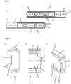
- rail system 1 comprises a first rail member 11 and a second rail member 12.
- the rail elements can easily be moved relative to one another with the aid of a bearing, in this case a ball cage 13 and sliding bodies or balls located therein, the direction of travel corresponding to the longitudinal direction A of the rail elements.
- the second rail member 12 is fixed in position from the viewer's perspective, while the first rail member 11 is movable relative to the second rail member.
- the first rail element 11 has a significantly greater extent in the longitudinal direction A than the second rail element 12.
- the second rail element 12 remains in the direction of travel A in all positions within the extent in the longitudinal direction A of the first rail element 11.
- the rail system 1 is shown in plan view in a position different from a first end position. It can be clearly seen that the first rail element 11 has a first lug 14 at its first end and the second rail element 12 has a projection 15 at its first end.
- the first rail element 11 In moving the rail system into a first end position, as in FIG. 1b ), the first rail element 11 is moved so far relative to the second rail element 12 that a first end position is reached in which no further method in this direction of travel, which runs parallel to the longitudinal direction A of the rail elements, is more possible.
- the first rail element 11 abuts with its lug 14 against a component of the ball cage 13, which in turn abuts against the first end of the second rail element 12.
- the projection 15 within a recess 16 of the tab 14, which in the in FIG. 1 selected representations is not visible, positioned.
- FIG. 2 are detailed views of the in FIG. 1 schematically shown in a plan view rail system shown in a first end position.
- FIG. 2a is a plan view of the first end of the first rail member 11 having a perpendicular to the longitudinal direction A extending first tab 14.
- the first tab 14 is a recess 16 which completely breaks through the tab 14 in the illustrated embodiment.
- the second rail element 12 which is covered by the first lug of the first rail element 11 in this plan view, is positioned such that the projection 15 of the second rail element 12 is positioned in the recess 16.
- the projection 15 has a cross-section corresponding to the recess 16 and is arranged with play within the recess.
- FIG. 2b is a partially cutaway view of a part FIG. 1b ), wherein in each case the first ends of the first and second rail element 11, 12 of the rail system 1 are shown in a first end position.
- the projection 15 is completely guided through the not visible in this representation recess 16.
- the projection 15 protrudes on the side facing away from the second rail member 12 side of the tab 14 beyond this tab.
- Figure 2c is a perspective view of the in FIG. 2b ), from which it can be seen that the arranged at the first end of the second rail member 12 projection 15 is positioned in the first end position in the recess 16 of the first tab 14 and is passed through this recess.
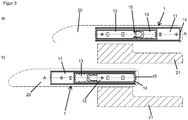
- FIG. 3 shows a console, in particular a center armrest of a vehicle 20, which is displaceable with respect to a base 21 by means of a rail system 1. It is a lateral plan view, with only the outlines of the center armrest 20 with a broken line and the contours of the base 21 are also shown with a broken line for clarity, with the base 21 is additionally hatched for identification.
- the rail system 1, which is used to move the center armrest, corresponds to the one in FIGS. 1 and 2 shown embodiments.
- FIG. 3a the center armrest is shown in a position in which no overload protection acts. This position corresponds to the one in FIG. 1a ) position of the rail system 1 FIG. 3b ), the center armrest 20 is displaced relative to the base 21, wherein the rail system 1 is in a first end position, the in FIG. 1b ) corresponds to the position shown.
- the detailed description of the rail system is therefore to the description too FIG. 1 directed.
- a center arm console is slidable along the longitudinal direction A of the rail system relative to a base 21, wherein in the illustrated embodiment, the first rail member 11 is fixedly connected to the center armrest 20, while the second rail member 12 is fixedly connected to the base 21.
Landscapes
- Engineering & Computer Science (AREA)
- Aviation & Aerospace Engineering (AREA)
- Transportation (AREA)
- Mechanical Engineering (AREA)
- Seats For Vehicles (AREA)
Claims (13)
- Système de rails (1) qui comprend au moins un premier (11) et un deuxième (12) éléments de rail, le premier et le deuxième éléments de rail étant déplaçables l'un par rapport à l'autre dans la direction longitudinale des rails, et le premier élément de rail comprenant, à une première extrémité, une première patte (14) s'étendant perpendiculairement à la direction longitudinale des éléments de rail, caractérisé en ce que la première patte du premier élément de rail comprend un évidement (16) et en ce que la première extrémité du deuxième élément de rail comprend une saillie (15) correspondant à l'évidement, laquelle saillie est positionnée, dans une première position finale, à l'intérieur de l'évidement.
- Système de rails (1) selon la revendication 1, caractérisé en ce que la saillie (15) correspondante est positionné au deuxième élément de rail (12), dans la première position finale, avec jeu dans l'évidement (16).
- Système de rails (1) selon la revendication 1 ou 2, caractérisé en ce que l'évidement (16) dans la première patte (14) traverse cette première patte entièrement et en ce que la saillie (15) correspondante au deuxième élément de rail (12) est passée, dans la première position finale, à travers l'évidement.
- Système de rails (1) selon l'une des revendications précédentes, caractérisé en ce que l'évidement (16) est, en une vue de dessus, une fente et en ce que la saillie (15) du deuxième élément de rail présente une section transversale rectangulaire.
- Système de rails (1) selon l'une des revendications précédentes, caractérisé en ce que ledit au moins un deuxième élément de rail (12) présente un profil en forme de C avec deux branches libres et une partie intermédiaire reliant l'une à l'autre les branches libres du profil en forme de C, l'évidement (16) étant disposé dans la patte (14) de façon telle qu'une saillie (15) correspondante, qui est formée par une extension de la partie intermédiaire de liaison, soit positionnée, dans une première position finale du deuxième élément de rail (12), à l'intérieur de l'évidement (16).
- Système de rails (1) selon l'une des revendications précédentes, caractérisé en ce que le premier élément de rail (11) présente un profil en C avec deux branches libres du profil et en ce que le deuxième élément de rail (12) s'étend à l'intérieur de la zone entourée par les branches libres.
- Système de rails (1) selon l'une des revendications précédentes, caractérisé en ce que le premier élément de rail (11) est plus long que le deuxième élément de rail (12) et en ce qu'un trajet de déplacement du premier élément de rail par rapport au deuxième élément de rail s'étend de la première position finale jusqu'à une deuxième position finale.
- Système de rails (1) selon l'une des revendications précédentes, caractérisé en ce que le premier élément de rail (11) présente un profil ayant essentiellement la forme d'un C avec deux branches libres et avec une partie intermédiaire reliant l'une à l'autre les branches libres, et en ce que la première patte (14) et/ou la deuxième patte est une extension repliée de la partie intermédiaire reliant entre elles les branches libres du profil en forme de C.
- Système de rails (1) selon l'une des revendications précédentes, caractérisé en ce que le système de rails comprend exactement un premier élément de rail (11) et exactement un second élément de rail (12).
- Système de rails (1) selon l'une des revendications précédentes, caractérisé en ce que ledit au moins un premier élément de rail (11) comprend, à une deuxième extrémité, une deuxième patte s'étendant perpendiculairement à la direction longitudinale des éléments de rail, laquelle patte comprend un évidement, un autre élément de rail ou le deuxième élément de rail (12) comprenant une saillie correspondant à l'évidement, la saillie étant positionnée, dans une deuxième position finale, à l'intérieur de l'évidement.
- Système de rails (1) selon l'une des revendications précédentes, caractérisé en ce que ledit au moins un premier (11) et/ou ledit au moins un deuxième (12) élément de rail est réalisé en métal léger, de préférence en aluminium.
- Console qui est déplaçable à l'aide d'au moins un système de rails (1) selon l'une des revendications précédentes.
- Accoudoir central (20) pour des véhicules, qui est déplaçable à l'aide d'au moins un système de rails (1) selon l'une des revendications 1 à 11.
Applications Claiming Priority (1)
| Application Number | Priority Date | Filing Date | Title |
|---|---|---|---|
| DE102012108306.1A DE102012108306A1 (de) | 2012-09-06 | 2012-09-06 | Überlastschutz |
Publications (2)
| Publication Number | Publication Date |
|---|---|
| EP2705979A1 EP2705979A1 (fr) | 2014-03-12 |
| EP2705979B1 true EP2705979B1 (fr) | 2018-04-25 |
Family
ID=49035456
Family Applications (1)
| Application Number | Title | Priority Date | Filing Date |
|---|---|---|---|
| EP13181969.0A Active EP2705979B1 (fr) | 2012-09-06 | 2013-08-28 | Protection contre les surcharges |
Country Status (2)
| Country | Link |
|---|---|
| EP (1) | EP2705979B1 (fr) |
| DE (1) | DE102012108306A1 (fr) |
Families Citing this family (7)
| Publication number | Priority date | Publication date | Assignee | Title |
|---|---|---|---|---|
| DE102014005620B4 (de) * | 2014-04-16 | 2016-11-03 | Grammer Ag | Staubunempfindliche Gleitschiene |
| US9849808B2 (en) | 2016-03-08 | 2017-12-26 | Honda Motor Co., Ltd. | End bracket for lateral slide rail for removable seat |
| WO2017184092A1 (fr) * | 2016-04-22 | 2017-10-26 | Assan Hanil Otomotiv Sanayi Ve Ticaret Anonim Sirketi | Mécanisme de réglage de siège |
| DE102016217848B4 (de) * | 2016-07-14 | 2021-08-12 | Adient Luxembourg Holding S.À R.L. | Längseinsteller sowie Fahrzeugsitz |
| JP6460083B2 (ja) * | 2016-11-09 | 2019-01-30 | トヨタ自動車株式会社 | 収納ボックス |
| CN107212647B (zh) * | 2016-12-08 | 2019-01-25 | 遵化市高强化纤有限公司 | 一种用于物品的收藏架装置 |
| CN114043913B (zh) * | 2021-12-15 | 2023-01-31 | 东风汽车集团股份有限公司 | 一种汽车自动扶手、扶手调节方法 |
Family Cites Families (10)
| Publication number | Priority date | Publication date | Assignee | Title |
|---|---|---|---|---|
| JPH0420664Y2 (fr) * | 1986-11-29 | 1992-05-12 | ||
| DE10011148A1 (de) * | 2000-03-07 | 2001-09-13 | Opel Adam Ag | Abdeckung für ein Schienenpaar eines Kraftfahrzeugsitzes |
| ATE432846T1 (de) * | 2002-04-22 | 2009-06-15 | Johnson Controls Tech Co | Artikelbefestigungssystem |
| DE202004013162U1 (de) * | 2004-08-23 | 2004-11-11 | King Slide Works Co., Ltd., Lu-Chu Hsiang | Halteanordnung für eine Schiebeeinrichtung |
| DE102006043988B4 (de) * | 2006-09-19 | 2013-07-25 | Isringhausen Gmbh & Co. Kg | Armlehne für einen Fahrzeugsitz sowie Fahrzeugsitz mit Armlehne |
| DE202006015291U1 (de) * | 2006-10-04 | 2007-01-25 | Kögl GmbH | Schubladenvollauszug mit Zwangsführung |
| WO2008072868A1 (fr) * | 2006-12-14 | 2008-06-19 | Yoon Sik Park | Mécanisme de blocage et glissière ainsi pourvue |
| CN101784415B (zh) * | 2007-10-11 | 2012-08-29 | 爱信精机株式会社 | 车辆用座椅滑动装置 |
| TWI422311B (zh) * | 2008-05-16 | 2014-01-01 | King Slide Works Co Ltd | 滑軌收合之定位裝置 |
| DE102011052265A1 (de) * | 2010-11-30 | 2012-05-31 | Paul Hettich Gmbh & Co. Kg | Ausstoßvorrichtung und Auszugsführung |
-
2012
- 2012-09-06 DE DE102012108306.1A patent/DE102012108306A1/de not_active Withdrawn
-
2013
- 2013-08-28 EP EP13181969.0A patent/EP2705979B1/fr active Active
Non-Patent Citations (1)
| Title |
|---|
| None * |
Also Published As
| Publication number | Publication date |
|---|---|
| EP2705979A1 (fr) | 2014-03-12 |
| DE102012108306A1 (de) | 2014-03-06 |
Similar Documents
| Publication | Publication Date | Title |
|---|---|---|
| EP2705979B1 (fr) | Protection contre les surcharges | |
| EP2624725B1 (fr) | Guide télescopique | |
| EP2694328B1 (fr) | Guide linéaire | |
| EP2183494B1 (fr) | Systeme de guidage lineaire comportant un rail a profile creux | |
| EP2593686B1 (fr) | Siège de véhicule avec un dispositif de réglage longitudinal comportant un guide à rails | |
| EP2983943A1 (fr) | Dispositif de réglage longitudinal d'un siège de véhicule et siège de véhicule | |
| EP2086791A1 (fr) | Dispositif de réglage longitudinal pour un siège de véhicule automobile | |
| DE10249698A1 (de) | Gleitschienensystem, insbesondere für Kraftfahrzeugsitze | |
| WO2012055721A1 (fr) | Appareil de blocage d'un dispositif de réglage en longueur d'un siège de véhicule doté de broches d'arrêt | |
| AT393351B (de) | Auszugfuehrung fuer einen ausziehbaren moebelteil, beispielsweise einen schubkasten | |
| DE10135161A1 (de) | Kugelgelagerte Teleskopschiene | |
| DE102014217331A1 (de) | Schienenanordnung für einen Fahrzeugsitz | |
| DE3914046A1 (de) | Laengsfuehrung, insbesondere fuer eine laengsverstelleinrichtung eines kraftfahrzeugsitzes | |
| EP2183493B1 (fr) | Systeme de guidage lineaire | |
| EP0790420B1 (fr) | Bloc a coulisse pour une colonne telescopique | |
| EP3724526B1 (fr) | Rail télescopique | |
| EP3233563A1 (fr) | Recouvrement pour une paire de rails d'un siège de véhicule ajustable en longueur, ainsi que paire de rails | |
| EP3819513B1 (fr) | Palier lisse, dispositif d'équipement pourvu d'au moins un palier lisse et dispositif d'équipement pourvu d'au moins un palier logé rotatif | |
| WO2007054487A1 (fr) | Vis d'entrainement a billes | |
| EP4265153A1 (fr) | Guide d'extraction | |
| DE102021214325A1 (de) | Teleskopsäule für einen höhenverstellbaren Tisch und höhenverstellbarer Tisch mit einer solchen Teleskopsäule | |
| WO2016079135A1 (fr) | Système de réglage d'un siège de véhicule | |
| DE102022120440A1 (de) | Schlitten für ein lineares Führungssystem und lineares Führungssystem mit einem solchen Schlitten | |
| DE102021133491A1 (de) | Einteiliger Endanschlag für Schwerlastschiene | |
| DE102022120080A1 (de) | Schlitten für ein lineares Führungssystem und lineares Führungssystem mit einem solchen Schlitten |
Legal Events
| Date | Code | Title | Description |
|---|---|---|---|
| PUAI | Public reference made under article 153(3) epc to a published international application that has entered the european phase |
Free format text: ORIGINAL CODE: 0009012 |
|
| AK | Designated contracting states |
Kind code of ref document: A1 Designated state(s): AL AT BE BG CH CY CZ DE DK EE ES FI FR GB GR HR HU IE IS IT LI LT LU LV MC MK MT NL NO PL PT RO RS SE SI SK SM TR |
|
| AX | Request for extension of the european patent |
Extension state: BA ME |
|
| 17P | Request for examination filed |
Effective date: 20140909 |
|
| RBV | Designated contracting states (corrected) |
Designated state(s): AL AT BE BG CH CY CZ DE DK EE ES FI FR GB GR HR HU IE IS IT LI LT LU LV MC MK MT NL NO PL PT RO RS SE SI SK SM TR |
|
| REG | Reference to a national code |
Ref country code: DE Ref legal event code: R079 Ref document number: 502013009995 Country of ref document: DE Free format text: PREVIOUS MAIN CLASS: B60N0002070000 Ipc: A47B0088500000 |
|
| GRAP | Despatch of communication of intention to grant a patent |
Free format text: ORIGINAL CODE: EPIDOSNIGR1 |
|
| RIC1 | Information provided on ipc code assigned before grant |
Ipc: A47B 88/50 20170101AFI20171127BHEP Ipc: B60N 2/07 20060101ALI20171127BHEP Ipc: B60N 2/46 00000000ALI20171127BHEP |
|
| INTG | Intention to grant announced |
Effective date: 20171220 |
|
| GRAS | Grant fee paid |
Free format text: ORIGINAL CODE: EPIDOSNIGR3 |
|
| GRAA | (expected) grant |
Free format text: ORIGINAL CODE: 0009210 |
|
| AK | Designated contracting states |
Kind code of ref document: B1 Designated state(s): AL AT BE BG CH CY CZ DE DK EE ES FI FR GB GR HR HU IE IS IT LI LT LU LV MC MK MT NL NO PL PT RO RS SE SI SK SM TR |
|
| REG | Reference to a national code |
Ref country code: GB Ref legal event code: FG4D Free format text: NOT ENGLISH |
|
| REG | Reference to a national code |
Ref country code: CH Ref legal event code: EP |
|
| REG | Reference to a national code |
Ref country code: AT Ref legal event code: REF Ref document number: 991913 Country of ref document: AT Kind code of ref document: T Effective date: 20180515 |
|
| REG | Reference to a national code |
Ref country code: IE Ref legal event code: FG4D Free format text: LANGUAGE OF EP DOCUMENT: GERMAN |
|
| REG | Reference to a national code |
Ref country code: DE Ref legal event code: R096 Ref document number: 502013009995 Country of ref document: DE |
|
| REG | Reference to a national code |
Ref country code: FR Ref legal event code: PLFP Year of fee payment: 6 |
|
| REG | Reference to a national code |
Ref country code: NL Ref legal event code: MP Effective date: 20180425 |
|
| REG | Reference to a national code |
Ref country code: LT Ref legal event code: MG4D |
|
| PG25 | Lapsed in a contracting state [announced via postgrant information from national office to epo] |
Ref country code: NL Free format text: LAPSE BECAUSE OF FAILURE TO SUBMIT A TRANSLATION OF THE DESCRIPTION OR TO PAY THE FEE WITHIN THE PRESCRIBED TIME-LIMIT Effective date: 20180425 |
|
| PG25 | Lapsed in a contracting state [announced via postgrant information from national office to epo] |
Ref country code: ES Free format text: LAPSE BECAUSE OF FAILURE TO SUBMIT A TRANSLATION OF THE DESCRIPTION OR TO PAY THE FEE WITHIN THE PRESCRIBED TIME-LIMIT Effective date: 20180425 Ref country code: LT Free format text: LAPSE BECAUSE OF FAILURE TO SUBMIT A TRANSLATION OF THE DESCRIPTION OR TO PAY THE FEE WITHIN THE PRESCRIBED TIME-LIMIT Effective date: 20180425 Ref country code: PL Free format text: LAPSE BECAUSE OF FAILURE TO SUBMIT A TRANSLATION OF THE DESCRIPTION OR TO PAY THE FEE WITHIN THE PRESCRIBED TIME-LIMIT Effective date: 20180425 Ref country code: NO Free format text: LAPSE BECAUSE OF FAILURE TO SUBMIT A TRANSLATION OF THE DESCRIPTION OR TO PAY THE FEE WITHIN THE PRESCRIBED TIME-LIMIT Effective date: 20180725 Ref country code: SE Free format text: LAPSE BECAUSE OF FAILURE TO SUBMIT A TRANSLATION OF THE DESCRIPTION OR TO PAY THE FEE WITHIN THE PRESCRIBED TIME-LIMIT Effective date: 20180425 Ref country code: FI Free format text: LAPSE BECAUSE OF FAILURE TO SUBMIT A TRANSLATION OF THE DESCRIPTION OR TO PAY THE FEE WITHIN THE PRESCRIBED TIME-LIMIT Effective date: 20180425 Ref country code: BG Free format text: LAPSE BECAUSE OF FAILURE TO SUBMIT A TRANSLATION OF THE DESCRIPTION OR TO PAY THE FEE WITHIN THE PRESCRIBED TIME-LIMIT Effective date: 20180725 |
|
| PG25 | Lapsed in a contracting state [announced via postgrant information from national office to epo] |
Ref country code: GR Free format text: LAPSE BECAUSE OF FAILURE TO SUBMIT A TRANSLATION OF THE DESCRIPTION OR TO PAY THE FEE WITHIN THE PRESCRIBED TIME-LIMIT Effective date: 20180726 Ref country code: RS Free format text: LAPSE BECAUSE OF FAILURE TO SUBMIT A TRANSLATION OF THE DESCRIPTION OR TO PAY THE FEE WITHIN THE PRESCRIBED TIME-LIMIT Effective date: 20180425 Ref country code: LV Free format text: LAPSE BECAUSE OF FAILURE TO SUBMIT A TRANSLATION OF THE DESCRIPTION OR TO PAY THE FEE WITHIN THE PRESCRIBED TIME-LIMIT Effective date: 20180425 Ref country code: HR Free format text: LAPSE BECAUSE OF FAILURE TO SUBMIT A TRANSLATION OF THE DESCRIPTION OR TO PAY THE FEE WITHIN THE PRESCRIBED TIME-LIMIT Effective date: 20180425 |
|
| PG25 | Lapsed in a contracting state [announced via postgrant information from national office to epo] |
Ref country code: PT Free format text: LAPSE BECAUSE OF FAILURE TO SUBMIT A TRANSLATION OF THE DESCRIPTION OR TO PAY THE FEE WITHIN THE PRESCRIBED TIME-LIMIT Effective date: 20180827 |
|
| REG | Reference to a national code |
Ref country code: DE Ref legal event code: R097 Ref document number: 502013009995 Country of ref document: DE |
|
| PG25 | Lapsed in a contracting state [announced via postgrant information from national office to epo] |
Ref country code: RO Free format text: LAPSE BECAUSE OF FAILURE TO SUBMIT A TRANSLATION OF THE DESCRIPTION OR TO PAY THE FEE WITHIN THE PRESCRIBED TIME-LIMIT Effective date: 20180425 Ref country code: CZ Free format text: LAPSE BECAUSE OF FAILURE TO SUBMIT A TRANSLATION OF THE DESCRIPTION OR TO PAY THE FEE WITHIN THE PRESCRIBED TIME-LIMIT Effective date: 20180425 Ref country code: SK Free format text: LAPSE BECAUSE OF FAILURE TO SUBMIT A TRANSLATION OF THE DESCRIPTION OR TO PAY THE FEE WITHIN THE PRESCRIBED TIME-LIMIT Effective date: 20180425 Ref country code: DK Free format text: LAPSE BECAUSE OF FAILURE TO SUBMIT A TRANSLATION OF THE DESCRIPTION OR TO PAY THE FEE WITHIN THE PRESCRIBED TIME-LIMIT Effective date: 20180425 Ref country code: EE Free format text: LAPSE BECAUSE OF FAILURE TO SUBMIT A TRANSLATION OF THE DESCRIPTION OR TO PAY THE FEE WITHIN THE PRESCRIBED TIME-LIMIT Effective date: 20180425 |
|
| REG | Reference to a national code |
Ref country code: CH Ref legal event code: PK Free format text: BERICHTIGUNGEN |
|
| RIC2 | Information provided on ipc code assigned after grant |
Ipc: B60N 2/46 20060101ALI20171127BHEP Ipc: A47B 88/50 20170101AFI20171127BHEP Ipc: B60N 2/07 20060101ALI20171127BHEP |
|
| PG25 | Lapsed in a contracting state [announced via postgrant information from national office to epo] |
Ref country code: SM Free format text: LAPSE BECAUSE OF FAILURE TO SUBMIT A TRANSLATION OF THE DESCRIPTION OR TO PAY THE FEE WITHIN THE PRESCRIBED TIME-LIMIT Effective date: 20180425 |
|
| PLBE | No opposition filed within time limit |
Free format text: ORIGINAL CODE: 0009261 |
|
| STAA | Information on the status of an ep patent application or granted ep patent |
Free format text: STATUS: NO OPPOSITION FILED WITHIN TIME LIMIT |
|
| PG25 | Lapsed in a contracting state [announced via postgrant information from national office to epo] |
Ref country code: MC Free format text: LAPSE BECAUSE OF FAILURE TO SUBMIT A TRANSLATION OF THE DESCRIPTION OR TO PAY THE FEE WITHIN THE PRESCRIBED TIME-LIMIT Effective date: 20180425 |
|
| REG | Reference to a national code |
Ref country code: CH Ref legal event code: PL |
|
| 26N | No opposition filed |
Effective date: 20190128 |
|
| GBPC | Gb: european patent ceased through non-payment of renewal fee |
Effective date: 20180828 |
|
| PG25 | Lapsed in a contracting state [announced via postgrant information from national office to epo] |
Ref country code: LU Free format text: LAPSE BECAUSE OF NON-PAYMENT OF DUE FEES Effective date: 20180828 Ref country code: LI Free format text: LAPSE BECAUSE OF NON-PAYMENT OF DUE FEES Effective date: 20180831 Ref country code: CH Free format text: LAPSE BECAUSE OF NON-PAYMENT OF DUE FEES Effective date: 20180831 |
|
| REG | Reference to a national code |
Ref country code: BE Ref legal event code: MM Effective date: 20180831 |
|
| PG25 | Lapsed in a contracting state [announced via postgrant information from national office to epo] |
Ref country code: SI Free format text: LAPSE BECAUSE OF FAILURE TO SUBMIT A TRANSLATION OF THE DESCRIPTION OR TO PAY THE FEE WITHIN THE PRESCRIBED TIME-LIMIT Effective date: 20180425 |
|
| PG25 | Lapsed in a contracting state [announced via postgrant information from national office to epo] |
Ref country code: BE Free format text: LAPSE BECAUSE OF NON-PAYMENT OF DUE FEES Effective date: 20180831 |
|
| REG | Reference to a national code |
Ref country code: AT Ref legal event code: MM01 Ref document number: 991913 Country of ref document: AT Kind code of ref document: T Effective date: 20180828 |
|
| PG25 | Lapsed in a contracting state [announced via postgrant information from national office to epo] |
Ref country code: GB Free format text: LAPSE BECAUSE OF NON-PAYMENT OF DUE FEES Effective date: 20180828 |
|
| PG25 | Lapsed in a contracting state [announced via postgrant information from national office to epo] |
Ref country code: AL Free format text: LAPSE BECAUSE OF FAILURE TO SUBMIT A TRANSLATION OF THE DESCRIPTION OR TO PAY THE FEE WITHIN THE PRESCRIBED TIME-LIMIT Effective date: 20180425 |
|
| PG25 | Lapsed in a contracting state [announced via postgrant information from national office to epo] |
Ref country code: AT Free format text: LAPSE BECAUSE OF NON-PAYMENT OF DUE FEES Effective date: 20180828 |
|
| PG25 | Lapsed in a contracting state [announced via postgrant information from national office to epo] |
Ref country code: MT Free format text: LAPSE BECAUSE OF FAILURE TO SUBMIT A TRANSLATION OF THE DESCRIPTION OR TO PAY THE FEE WITHIN THE PRESCRIBED TIME-LIMIT Effective date: 20180425 |
|
| PG25 | Lapsed in a contracting state [announced via postgrant information from national office to epo] |
Ref country code: TR Free format text: LAPSE BECAUSE OF FAILURE TO SUBMIT A TRANSLATION OF THE DESCRIPTION OR TO PAY THE FEE WITHIN THE PRESCRIBED TIME-LIMIT Effective date: 20180425 |
|
| PG25 | Lapsed in a contracting state [announced via postgrant information from national office to epo] |
Ref country code: HU Free format text: LAPSE BECAUSE OF FAILURE TO SUBMIT A TRANSLATION OF THE DESCRIPTION OR TO PAY THE FEE WITHIN THE PRESCRIBED TIME-LIMIT; INVALID AB INITIO Effective date: 20130828 |
|
| PG25 | Lapsed in a contracting state [announced via postgrant information from national office to epo] |
Ref country code: IE Free format text: LAPSE BECAUSE OF NON-PAYMENT OF DUE FEES Effective date: 20180828 Ref country code: MK Free format text: LAPSE BECAUSE OF NON-PAYMENT OF DUE FEES Effective date: 20180425 Ref country code: CY Free format text: LAPSE BECAUSE OF FAILURE TO SUBMIT A TRANSLATION OF THE DESCRIPTION OR TO PAY THE FEE WITHIN THE PRESCRIBED TIME-LIMIT Effective date: 20180425 |
|
| PG25 | Lapsed in a contracting state [announced via postgrant information from national office to epo] |
Ref country code: IS Free format text: LAPSE BECAUSE OF FAILURE TO SUBMIT A TRANSLATION OF THE DESCRIPTION OR TO PAY THE FEE WITHIN THE PRESCRIBED TIME-LIMIT Effective date: 20180825 |
|
| PGFP | Annual fee paid to national office [announced via postgrant information from national office to epo] |
Ref country code: IT Payment date: 20230825 Year of fee payment: 11 |
|
| PGFP | Annual fee paid to national office [announced via postgrant information from national office to epo] |
Ref country code: FR Payment date: 20230824 Year of fee payment: 11 Ref country code: DE Payment date: 20230822 Year of fee payment: 11 |