EP2183493B1 - Systeme de guidage lineaire - Google Patents
Systeme de guidage lineaire Download PDFInfo
- Publication number
- EP2183493B1 EP2183493B1 EP08787426.9A EP08787426A EP2183493B1 EP 2183493 B1 EP2183493 B1 EP 2183493B1 EP 08787426 A EP08787426 A EP 08787426A EP 2183493 B1 EP2183493 B1 EP 2183493B1
- Authority
- EP
- European Patent Office
- Prior art keywords
- guide rail
- ball cage
- balls
- carriage
- shaped
- Prior art date
- Legal status (The legal status is an assumption and is not a legal conclusion. Google has not performed a legal analysis and makes no representation as to the accuracy of the status listed.)
- Active
Links
- 238000005096 rolling process Methods 0.000 claims description 3
- 238000004519 manufacturing process Methods 0.000 description 5
- 239000000314 lubricant Substances 0.000 description 2
- 229910000831 Steel Inorganic materials 0.000 description 1
- 229910052782 aluminium Inorganic materials 0.000 description 1
- XAGFODPZIPBFFR-UHFFFAOYSA-N aluminium Chemical compound [Al] XAGFODPZIPBFFR-UHFFFAOYSA-N 0.000 description 1
- 238000005260 corrosion Methods 0.000 description 1
- 230000007797 corrosion Effects 0.000 description 1
- 238000009826 distribution Methods 0.000 description 1
- 239000013013 elastic material Substances 0.000 description 1
- 238000001125 extrusion Methods 0.000 description 1
- 229910052751 metal Inorganic materials 0.000 description 1
- 239000002184 metal Substances 0.000 description 1
- 238000000034 method Methods 0.000 description 1
- 230000006641 stabilisation Effects 0.000 description 1
- 238000011105 stabilization Methods 0.000 description 1
- 229910001220 stainless steel Inorganic materials 0.000 description 1
- 239000010935 stainless steel Substances 0.000 description 1
- 239000010959 steel Substances 0.000 description 1
- 238000003860 storage Methods 0.000 description 1
Images

Classifications
-
- E—FIXED CONSTRUCTIONS
- E05—LOCKS; KEYS; WINDOW OR DOOR FITTINGS; SAFES
- E05D—HINGES OR SUSPENSION DEVICES FOR DOORS, WINDOWS OR WINGS
- E05D15/00—Suspension arrangements for wings
- E05D15/06—Suspension arrangements for wings for wings sliding horizontally more or less in their own plane
- E05D15/0621—Details, e.g. suspension or supporting guides
- E05D15/0626—Details, e.g. suspension or supporting guides for wings suspended at the top
- E05D15/0643—Details, e.g. suspension or supporting guides for wings suspended at the top on balls or floating rollers
-
- F—MECHANICAL ENGINEERING; LIGHTING; HEATING; WEAPONS; BLASTING
- F16—ENGINEERING ELEMENTS AND UNITS; GENERAL MEASURES FOR PRODUCING AND MAINTAINING EFFECTIVE FUNCTIONING OF MACHINES OR INSTALLATIONS; THERMAL INSULATION IN GENERAL
- F16C—SHAFTS; FLEXIBLE SHAFTS; ELEMENTS OR CRANKSHAFT MECHANISMS; ROTARY BODIES OTHER THAN GEARING ELEMENTS; BEARINGS
- F16C29/00—Bearings for parts moving only linearly
- F16C29/04—Ball or roller bearings
-
- F—MECHANICAL ENGINEERING; LIGHTING; HEATING; WEAPONS; BLASTING
- F16—ENGINEERING ELEMENTS AND UNITS; GENERAL MEASURES FOR PRODUCING AND MAINTAINING EFFECTIVE FUNCTIONING OF MACHINES OR INSTALLATIONS; THERMAL INSULATION IN GENERAL
- F16C—SHAFTS; FLEXIBLE SHAFTS; ELEMENTS OR CRANKSHAFT MECHANISMS; ROTARY BODIES OTHER THAN GEARING ELEMENTS; BEARINGS
- F16C29/00—Bearings for parts moving only linearly
- F16C29/12—Arrangements for adjusting play
- F16C29/123—Arrangements for adjusting play using elastic means
-
- F—MECHANICAL ENGINEERING; LIGHTING; HEATING; WEAPONS; BLASTING
- F16—ENGINEERING ELEMENTS AND UNITS; GENERAL MEASURES FOR PRODUCING AND MAINTAINING EFFECTIVE FUNCTIONING OF MACHINES OR INSTALLATIONS; THERMAL INSULATION IN GENERAL
- F16C—SHAFTS; FLEXIBLE SHAFTS; ELEMENTS OR CRANKSHAFT MECHANISMS; ROTARY BODIES OTHER THAN GEARING ELEMENTS; BEARINGS
- F16C33/00—Parts of bearings; Special methods for making bearings or parts thereof
- F16C33/30—Parts of ball or roller bearings
- F16C33/38—Ball cages
- F16C33/3837—Massive or moulded cages having cage pockets surrounding the balls, e.g. machined window cages
- F16C33/3843—Massive or moulded cages having cage pockets surrounding the balls, e.g. machined window cages formed as one-piece cages, i.e. monoblock cages
- F16C33/3856—Massive or moulded cages having cage pockets surrounding the balls, e.g. machined window cages formed as one-piece cages, i.e. monoblock cages made from plastic, e.g. injection moulded window cages
-
- E—FIXED CONSTRUCTIONS
- E05—LOCKS; KEYS; WINDOW OR DOOR FITTINGS; SAFES
- E05Y—INDEXING SCHEME ASSOCIATED WITH SUBCLASSES E05D AND E05F, RELATING TO CONSTRUCTION ELEMENTS, ELECTRIC CONTROL, POWER SUPPLY, POWER SIGNAL OR TRANSMISSION, USER INTERFACES, MOUNTING OR COUPLING, DETAILS, ACCESSORIES, AUXILIARY OPERATIONS NOT OTHERWISE PROVIDED FOR, APPLICATION THEREOF
- E05Y2201/00—Constructional elements; Accessories therefor
- E05Y2201/60—Suspension or transmission members; Accessories therefor
- E05Y2201/622—Suspension or transmission members elements
- E05Y2201/684—Rails; Tracks
-
- E—FIXED CONSTRUCTIONS
- E05—LOCKS; KEYS; WINDOW OR DOOR FITTINGS; SAFES
- E05Y—INDEXING SCHEME ASSOCIATED WITH SUBCLASSES E05D AND E05F, RELATING TO CONSTRUCTION ELEMENTS, ELECTRIC CONTROL, POWER SUPPLY, POWER SIGNAL OR TRANSMISSION, USER INTERFACES, MOUNTING OR COUPLING, DETAILS, ACCESSORIES, AUXILIARY OPERATIONS NOT OTHERWISE PROVIDED FOR, APPLICATION THEREOF
- E05Y2800/00—Details, accessories and auxiliary operations not otherwise provided for
- E05Y2800/10—Additional functions
- E05Y2800/122—Telescopic action
-
- E—FIXED CONSTRUCTIONS
- E05—LOCKS; KEYS; WINDOW OR DOOR FITTINGS; SAFES
- E05Y—INDEXING SCHEME ASSOCIATED WITH SUBCLASSES E05D AND E05F, RELATING TO CONSTRUCTION ELEMENTS, ELECTRIC CONTROL, POWER SUPPLY, POWER SIGNAL OR TRANSMISSION, USER INTERFACES, MOUNTING OR COUPLING, DETAILS, ACCESSORIES, AUXILIARY OPERATIONS NOT OTHERWISE PROVIDED FOR, APPLICATION THEREOF
- E05Y2900/00—Application of doors, windows, wings or fittings thereof
- E05Y2900/50—Application of doors, windows, wings or fittings thereof for vehicles
- E05Y2900/53—Type of wing
- E05Y2900/531—Doors
Definitions
- the present invention relates to a linear guide system with a guide rail and a guided over at least two ball bearings guided carriage, wherein the ball bearings each comprise a plurality of balls and a strip-shaped ball cage and the guide rail running surfaces and the carriage treads for rolling the balls of the ball bearings.
- Linear guidance systems can be used in a wide variety of areas. In the automotive industry, linear guide systems with high load capacity are used. used for vehicle sliding doors, load floors, longitudinally adjustable consoles in the vehicle interior and other facilities.
- guide rails are frequently mounted on the outside of the body on which the sliding doors are guided. Although such an assembly on the outside of the body ensures high stability of the guide system under the burden of the weight of the sliding door, however, mounted on the outside of the body guide rails are visible with the sliding door closed and disturb the appearance considerably.
- these guide rails are constantly exposed to external weather conditions and therefore corrode faster than guide systems mounted inside or require significantly higher corrosion protection.
- such guide rails are profiled so that dirt from the environment on and in the rails quickly accumulates and the running characteristics of the guide system are thereby deteriorated very quickly.
- a sliding door for motor vehicles with a guide rail mounted on the inside of the door in which some of the aforementioned disadvantages of guide rails mounted on the outside of the body are overcome, discloses DE 4314115 A1 ,
- the guide system described for a motor vehicle sliding door has no particularly good running properties and thus no good feel and is relatively loud.
- the US-A-4,655,613 describes a ball-bearing linear guide with a strip-shaped ball cage with a plurality of successively arranged in series, substantially circular through holes into which the balls are inserted, wherein the edge regions of the through holes are adapted to the spherical outer surface of the balls and in the direction of both running surfaces of the mutually movable Rejuvenate rail elements, so that the balls are secured in the through holes against falling out of the through holes.
- the object of the present invention was to provide a linear guide system that can carry high loads, has a low noise, has a compact design, allows large travel paths and is relatively inexpensive to manufacture.
- Another object of the invention was to provide a linear guide system for vehicle sliding doors, load floors, longitudinally adjustable consoles in the vehicle interior, etc. with the aforementioned properties.
- the balls sit in the passage openings and are against falling upwards, d. H. in the direction from a running surface of the guide rail to the associated running surface of the carriage, secured by either the inner diameter of the through holes is tapered conically to an inner diameter which is smaller than the diameter of the balls, or by being restricted by limiting means to an inner diameter which is smaller than the diameter of the balls.
- elastically deformable retaining means are provided at the through openings of the ball cage, which are designed so that they secure the balls against falling out of the through holes in the direction of the ball cage arranged under the running surface of the guide rail, if the balls do not rest on the tread , Since the balls are held by the ball cage and the upper holding means with a bias against the running surfaces of the guide rail, this backup comes only to bear, if the balls do not rest against the tread, z. B. during assembly and storage of the ball cage.
- the elastically deformable holding means in the direction of the arranged under the ball cage tread are formed as elastically biased to the center of the through holes webs. Since these holding means are required only when the balls do not abut the tread, it is sufficient if one or two such webs is provided at each through hole to secure the ball in the through hole against falling out. Of course, several such webs may be provided.
- the holding means or webs are briefly pressed apart so that a ball can be used.
- the strip-shaped ball cage according to the invention is simple and inexpensive to manufacture and to mount on the guide rail and offers good running properties for the linear guide system.
- the length of the ball cage and the number of balls and through holes arranged therein depends essentially on the overall length of the guide system and the travel, but also on the required load capacity of the linear guide system, the desired feel and smoothness.
- the balls are held by the ball cage with a bias against the running surfaces of the guide rail. This ensures that the balls are always in contact with the running surfaces of the guide rail, whereby a rattling and disturbing noise of the ball bearing, e.g. in vibration, be avoided, even in the balls that are not under load between the running rail and the carriage.
- the ball cage is elastically deformable or flexible.
- the side edges engage in the longitudinal extent of the strip-shaped ball cage in two mutually opposite in the longitudinal extent of the guide rail grooves for the attachment of the ball cage on the guide rail.
- the side edges of the strip-shaped ball cage are introduced.
- the arrangement of the grooves is chosen so that the ball cage is slightly bent during attachment transversely to its longitudinal axis and due to its flexibility or elasticity, the balls always presses with a bias against the tread of the guide rail.
- the strip-shaped ball cage is therefore made of a flexible, elastic material, preferably plastic. However, it can also be made of metal, for example steel or stainless steel.
- the guide rail on two opposite sides in each case a running surface and a ball bearing.
- more than two running surfaces and two ball bearings may be provided on the guide rail, for example two running surfaces and two ball bearings on each side of the guide rail.
- the total length of the linear guide system is essentially determined by the length of the guide rail.
- the guided on the guide rail carriage is considerably shorter than the guide rail.
- the maximum travel is determined by the overall length of the guide rail and the ratio of the length of the carriage to the length of the guide rail. For a given length of the guide rail, the maximum possible travel for an object attached to the carriage is the longer the shorter the carriage.
- the selection of the length of the guided on the guide rail carriage guided determines not only the desired travel, but also the required load capacity and stability of the linear guide system. The longer the carriage is, the higher the load capacity, running stability and smoothness, since the same design ball bearing a longer carriage is simultaneously unrolled to more balls than a shorter carriage.
- the carriage comprises a cross-sectionally substantially C-shaped profile whose respective end portions have running surfaces and engage around the guide rail in the region of the ball bearings.
- the carriage further comprises a plate which extends between the end portions of the substantially C-shaped profile of the carriage and with the end portions insoluble or releasably, preferably non-detachably, more preferably by means of a welded joint is connected ,
- the C-shaped profile and the plate attached to its end portions thus completely surround the guide rail like a tubular closed profile.
- the strip-shaped ball cage in its longitudinal extent at least in sections, preferably over its entire length, at least one Torsionsnut (groove-shaped recess).
- the at least one Torsionsnut is arranged on the running surfaces of the guide rail side facing the ball cage.
- This at least one Torsionsnut influenced or changed the elastic flexibility of the strip-shaped ball cage transversely to its longitudinal axis. Due to the width and depth of the at least one Torsionsnut the biasing force of the balls can be varied or adjusted against the running surfaces of the guide rail.
- Another advantage of the at least one Torsionsnut is that it can serve as a reservoir for a lubricant commonly used in ball bearings.
- the strip-shaped ball cage on the side facing away from the running surfaces of the guide rail on several in the vicinity of the side edges in the longitudinal direction of the ball cage and in series successively arranged knob-shaped elevations have several advantages.
- the entire ball cage in the longitudinal direction of the guide rail is also mitvon or -verschoben.
- the knob-shaped elevations near the side edges of the strip-shaped ball cage reduce the contact surface of the areas of the side edges within the provided on the guide rail for holding the ball cage grooves and thus the frictional resistance.
- the knob-shaped elevations ensure a good distribution of lubricant, which is expediently provided in the grooves on the guide rail for easier movement of the ball cage.
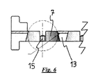
- the strip-shaped ball cage at its two end portions on end stops, which are designed so that the carriage can not be moved across one end of the ball cage away, but strikes the end stop on reaching one end of the ball cage. If this occurs and if the end of the guide rail has not yet been reached when moving the carriage, then the carriage takes or pulls the ball cage with it to the end of the travel path.
- end stops at the respective ends of the ball cage ensures that the carriage always remains with its full length above the ball cage and is not moved beyond this. This improves stability, running properties and load capacity of the guide system according to the invention.
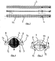
- FIG. 1 is a perspective view obliquely from above on a particularly preferred embodiment of the linear guide system according to the invention with a guide rail 1, a carriage 2 and two ball bearings 3 and 3 '.
- the guide rail 1 in this invention particularly preferred embodiment as a profile produced by extrusion, preferably made of aluminum.
- the guide rail 1 has a substantially box-shaped profile, which has cavities and stabilization struts inside.
- the ball cage 5 is equipped with balls 4, which are secured upwards against falling out, characterized in that the inner diameter of the through holes tapers conically.
- the ball cage 5 holds the balls 4 with a bias against the running surfaces 9 and 9 'of the guide rail 1 pressed.
- the carriage 2 consists of a substantially C-shaped profile 11 and a plate 12 connected to the end portions 11 'and 11 "of the C-shaped profile 11.
- the plate 12 is connected to the end portions 11' and 11" the C-shaped profile 11 welded.
- the plate 12 is a perforated plate.
- the perforated plate 12 can be used to secure an object to be moved when the guide rail is mounted stationary.
- the carriage 2 can be fixed via the perforated plate 12 and the guide rail 1 can be fastened to an object to be moved, such as a vehicle sliding door.
- the attachment of the guide rail is usually via fittings which are attached to the respective ends of the guide rail (not shown).
- FIG. 3 shows the strip-shaped ball cage 5 in this illustration only two arranged in the through holes 7 balls 4. It goes without saying that in a fully assembled linear guide system in each or at least most of the through holes 7, a ball 4 is provided.
- FIG. 4 shows an enlarged cross-sectional view of the ball cage 5 according to FIG. 3 along the section line CC.
- the conical taper of the inner diameter of the through hole 7 and the holding means 15 designed as elastic webs can be seen.
- the conically tapered wall surface 8 of the through hole lies above the center plane of the ball at this and the holding means 15 are below the median plane of the ball at this and thus secure the ball against falling out of the through hole. 7
- knob-shaped elevations 14 are arranged on the ball cage 5 in the vicinity of the side edges.
- FIG. 3 Lower illustration, shows that the knob-shaped elevations 14 are arranged in rows one behind the other and at regular intervals on the upper side of the ball cage 5. The knob-shaped elevations 14 reduce the contact surface of the ball cage in the grooves 6 and 6 'on the guide rail 1 and thus the frictional resistance.
- FIG. 5 shows a cross section through the ball cage 5 according to FIG. 3 along the section line DD.
- FIG. 5 shows essentially the same sectional view as FIG. 4 but without a ball inserted into the cut through hole 7.
- the ball cage 5 on the underside a Torsionsnut 13 (groove-shaped recess) which extends substantially over the entire length of the ball cage and by which the flexibility and elasticity of the ball cage is influenced transversely to its longitudinal extent.
- the width and depth of the Torsionsnut 13 thus the bias (biasing force) of the balls against the running surfaces 9 and 9 'of the guide rail 1 can be varied or adjusted.
- a Torsionsnut although this passes through the through holes of the ball cage and in the through holes actually no more groove represents.
- one could also speak of many individual (small) torsion grooves which extend in the areas between adjacent passage openings in the longitudinal direction of the ball cage.
- FIG. 6 shows a section through the strip-shaped ball cage according to FIG. 3 along the section line FF.
- the end portions of the strip-shaped ball cage upstanding end stops which are designed so that the carriage can not be moved across one end of the ball cage away.
Landscapes
- Engineering & Computer Science (AREA)
- General Engineering & Computer Science (AREA)
- Mechanical Engineering (AREA)
- Bearings For Parts Moving Linearly (AREA)
- Support Devices For Sliding Doors (AREA)
Claims (8)
- Système de guidage linéaire comprenant un rail de guidage (1) et un curseur (2) guidé en translation le long de ce rail par l'intermédiaire d'au moins deux roulements à billes (3, 3'), les roulements à billes comprenant chacun plusieurs billes (4) et une cage à billes (5) en forme de bande, le rail de guidage (1) présentant des surfaces de roulement (9, 9') et le curseur (2) présentant des surfaces de roulement (10, 10') pour le roulement des billes (4) des roulements à billes (3, 3'),
la cage à billes (5) présentant plusieurs ouvertures de passage sensiblement circulaires (7) disposées en une rangée l'une derrière l'autre et dans lesquelles les billes (4) sont emboîtées,
le diamètre intérieur des ouvertures de passage diminuant de façon conique, ou étant rétréci par des moyens de limitation, dans la direction allant d'une surface de roulement (9, 9') du rail de guidage vers la surface de roulement correspondante (10, 10') du curseur (2), pour atteindre un diamètre intérieur qui est plus petit que le diamètre des billes, de sorte que les billes sont retenues dans les ouvertures de passage (7) et empêchées de s'échapper des ouvertures de passage (7) en direction de la surface de roulement (10, 10') du curseur,
la cage à billes (5) étant de constitution élastiquement déformable et étant fixée au rail de guidage (1),
les billes (4) étant maintenues appuyées contre les surfaces de roulement (9, 9') du rail de guidage avec une précontrainte par la cage à billes (5),
caractérisé en ce que, sur la cage à billes (5), au moins par endroits dans son extension longitudinale et de préférence sur toute sa longueur, est prévue une rainure de torsion (13) qui est disposée sur le côté de la cage à billes (5) dirigé vers les surfaces de roulement (9, 9') du rail de guidage (1). - Système de guidage linéaire selon la revendication 1, caractérisé en ce qu'au niveau des ouvertures de passage (7) de la cage à billes (5), sont prévus des moyens de retenue élastiquement déformables (15) qui sont de constitution telle qu'ils empêchent les billes de tomber des ouvertures de passage (7) en direction de la surface de roulement (9, 9') du rail de guidage qui est disposée sous la cage à billes (5) lorsque les billes (4) ne sont pas en appui sur la surface de roulement (9, 9').
- Système de guidage linéaire selon une des revendications précédentes, caractérisé en ce que les bords latéraux (5', 5"), dans l'extension longitudinale de la cage à billes (5) en forme de bande, sont engagés dans deux rainures mutuellement opposées (6, 6') dans l'extension longitudinale du rail de guidage (1) pour assurer la fixation de la cage à billes (5) au rail de guidage.
- Système de guidage linéaire selon une des revendications précédentes, caractérisé en ce que la cage à billes en forme de bande (5) est fabriquée en matière plastique.
- Système de guidage linéaire selon une des revendications précédentes, caractérisé en ce que le rail de guidage (1) présente exactement une surface de roulement (9, 9') et un roulement à billes sur chacun de deux côtés mutuellement opposés.
- Système de guidage linéaire selon une des revendications précédentes, caractérisé en ce que le curseur (2) comprend un profilé (11) sensiblement en forme de C en coupe transversale dont les segments terminaux (11', 11 ") présentent des surfaces de roulement (10, 10') et encadrent le rail de guidage (1) dans la région des roulements à billes.
- Système de guidage linéaire selon la revendication 6, caractérisé en ce que le curseur (2) comprend en outre une plaque (12) qui s'étend entre les segments terminaux (11', 11 ") du profilé sensiblement en forme de C (11) du curseur (2), et qui est assemblée aux segments terminaux (11', 11 ") de façon indémontable ou démontable, de préférence indémontable, et dans un mode particulièrement préféré, au moyen d'un assemblage soudé.
- Système de guidage linéaire selon une des revendications précédentes, caractérisé en ce que la cage à billes (5) en forme de bande présente sur le côté éloigné des surfaces de roulement (9, 9') du rail de guidage (1), plusieurs saillies (14) en forme de bouton, disposées à proximité des bords latéraux dans l'extension longitudinale de la cage à billes (5) et en rangée l'une derrière l'autre.
Applications Claiming Priority (2)
| Application Number | Priority Date | Filing Date | Title |
|---|---|---|---|
| DE102007040230 | 2007-08-25 | ||
| PCT/EP2008/061027 WO2009027342A1 (fr) | 2007-08-25 | 2008-08-22 | Système de guidage linéaire |
Publications (2)
| Publication Number | Publication Date |
|---|---|
| EP2183493A1 EP2183493A1 (fr) | 2010-05-12 |
| EP2183493B1 true EP2183493B1 (fr) | 2015-06-17 |
Family
ID=40469776
Family Applications (1)
| Application Number | Title | Priority Date | Filing Date |
|---|---|---|---|
| EP08787426.9A Active EP2183493B1 (fr) | 2007-08-25 | 2008-08-22 | Systeme de guidage lineaire |
Country Status (5)
| Country | Link |
|---|---|
| US (1) | US8240916B2 (fr) |
| EP (1) | EP2183493B1 (fr) |
| JP (1) | JP5590399B2 (fr) |
| CN (1) | CN101821521B (fr) |
| WO (1) | WO2009027342A1 (fr) |
Families Citing this family (5)
| Publication number | Priority date | Publication date | Assignee | Title |
|---|---|---|---|---|
| EP2863774B1 (fr) | 2012-06-25 | 2017-02-22 | Paul Hettich GmbH & Co. KG | Dispositif de guidage de tiroir pour des pièces de meubles mobiles les unes par rapport aux autres comprenant un système de palier de corps de roulement |
| DE102015000019A1 (de) * | 2015-01-07 | 2016-07-07 | Trw Automotive Gmbh | Gurtschlossbringer |
| CN107781297A (zh) * | 2016-08-31 | 2018-03-09 | 泰州市创新电子有限公司 | 一种外轨为包覆套式的滚珠滑轨 |
| JP2019082037A (ja) * | 2017-10-30 | 2019-05-30 | 株式会社Lixil | 戸車 |
| CN109363524B (zh) * | 2018-11-16 | 2024-02-27 | 广东新宝电器股份有限公司 | 用于电烤箱的滑移门机构及电烤箱 |
Family Cites Families (24)
| Publication number | Priority date | Publication date | Assignee | Title |
|---|---|---|---|---|
| GB738486A (en) * | 1952-01-02 | 1955-10-12 | Ronald Robert Stewart Charteri | Improvements in or relating to supports for closure members, such as doors for vehicles |
| US2812222A (en) * | 1954-06-18 | 1957-11-05 | Grant Pulley & Hardware Corp | Permanent ball retainer for sliding members |
| US3113807A (en) * | 1961-10-12 | 1963-12-10 | Automation Gages Inc | Ball slide |
| US3145065A (en) * | 1961-12-26 | 1964-08-18 | Bausch & Lomb | Bearing assembly |
| US3801166A (en) * | 1973-01-05 | 1974-04-02 | Fall H | Drawer slide bearing retainer lock |
| DE2851305A1 (de) * | 1978-11-27 | 1980-06-04 | Hettich Paul & Co | Auszugfuehrung fuer schubkaesten |
| JPS616421U (ja) * | 1984-06-18 | 1986-01-16 | トヨタ車体株式会社 | 車両用スライドドアのガイドレ−ル構造 |
| US4655613A (en) * | 1984-07-10 | 1987-04-07 | Nippon Thompson Co., Ltd. | Linear motion rolling contact bearing assembly |
| US4629260A (en) * | 1985-05-07 | 1986-12-16 | Nippon Thompson Co., Ltd. | Piggyback rolling-contact bearing assembly |
| GB2213211B (en) | 1985-07-06 | 1990-01-24 | Firsteel Metal Prod | Bearing cages |
| GB2233215B (en) * | 1989-06-14 | 1992-06-10 | Sugatsune Kogyo | Slide rail assembly |
| US4991981A (en) * | 1990-05-14 | 1991-02-12 | Waterloo Metal Stampings Ltd. | Ball bearing retainer for drawer slides |
| DE4025011A1 (de) * | 1990-08-07 | 1992-02-13 | Werner Dipl Ing Jacob | Kugelfuehrung |
| US5106207A (en) * | 1991-03-25 | 1992-04-21 | Automation Gages, Inc. | Ball slide designed for extended travel |
| TW205587B (fr) * | 1991-09-18 | 1993-05-11 | American Telephone & Telegraph | |
| US5201584A (en) * | 1991-09-18 | 1993-04-13 | At&T Bell Laboratories | Mechanism for preloading linear bearing slides |
| JP2568320Y2 (ja) * | 1992-07-31 | 1998-04-08 | 日本トムソン株式会社 | 直動転がり案内ユニット |
| DE4314115A1 (de) | 1993-04-29 | 1994-11-03 | Opel Adam Ag | Schiebetür, insbesondere für Kraftfahrzeuge |
| DE29604922U1 (de) | 1996-03-16 | 1996-05-30 | REME Möbelbeschläge GmbH, 33161 Hövelhof | Auszugschiene |
| US6105920A (en) * | 1996-06-06 | 2000-08-22 | Lear Corporation | Vehicle power seat adjuster with hidden floor mount |
| US6655763B2 (en) * | 2000-12-22 | 2003-12-02 | Jonathan Engineered Solutions | Controller for a quick disconnect slide assembly |
| JP2003065350A (ja) * | 2001-08-28 | 2003-03-05 | Ntn Corp | トリポード型等速自在継手 |
| CN2911303Y (zh) * | 2006-03-23 | 2007-06-13 | 晟铭电子科技股份有限公司 | 具有双向固持滚珠的滑轨结构 |
| JP5215131B2 (ja) * | 2008-10-31 | 2013-06-19 | 京セラドキュメントソリューションズ株式会社 | 画像形成装置および感光体の回転同期方法 |
-
2008
- 2008-08-22 CN CN200880106143.3A patent/CN101821521B/zh active Active
- 2008-08-22 EP EP08787426.9A patent/EP2183493B1/fr active Active
- 2008-08-22 JP JP2010521440A patent/JP5590399B2/ja active Active
- 2008-08-22 US US12/733,343 patent/US8240916B2/en active Active
- 2008-08-22 WO PCT/EP2008/061027 patent/WO2009027342A1/fr active Application Filing
Also Published As
| Publication number | Publication date |
|---|---|
| EP2183493A1 (fr) | 2010-05-12 |
| US20100316311A1 (en) | 2010-12-16 |
| CN101821521A (zh) | 2010-09-01 |
| JP2010536644A (ja) | 2010-12-02 |
| CN101821521B (zh) | 2013-06-19 |
| WO2009027342A1 (fr) | 2009-03-05 |
| US8240916B2 (en) | 2012-08-14 |
| JP5590399B2 (ja) | 2014-09-17 |
Similar Documents
| Publication | Publication Date | Title |
|---|---|---|
| EP2183494B1 (fr) | Systeme de guidage lineaire comportant un rail a profile creux | |
| EP2694328B1 (fr) | Guide linéaire | |
| DE102012100287B4 (de) | Fahrzeugsitz | |
| EP2405786B1 (fr) | Glissière de tiroir | |
| DE102008023246A1 (de) | Fallende Raste und Bewegungskrafteinstellung | |
| EP2593686B1 (fr) | Siège de véhicule avec un dispositif de réglage longitudinal comportant un guide à rails | |
| EP2183493B1 (fr) | Systeme de guidage lineaire | |
| WO2014166833A1 (fr) | Dispositif de réglage longitudinal d'un siège de véhicule et siège de véhicule | |
| EP2168457A2 (fr) | Guidage d'extraction de meuble pour un élément coulissant de meuble | |
| DE102020203210A1 (de) | Lenksäule für ein Kraftfahrzeug | |
| WO2015032655A1 (fr) | Dispositif d'enroulement pour un système de store, système de store et dispositif de toit | |
| DE10249698A1 (de) | Gleitschienensystem, insbesondere für Kraftfahrzeugsitze | |
| DE69200650T2 (de) | Fahrzeugsitzschiene mit einer Vorrichtung für Spielverringerung und Geräuschunterdrückung. | |
| WO2000035705A1 (fr) | Rail de guidage de glissiere de composantes de vehicules et son procede de production | |
| EP2215928A2 (fr) | Rail d'un guidage d'extraction de meuble | |
| EP3724526B1 (fr) | Rail télescopique | |
| EP3233563A1 (fr) | Recouvrement pour une paire de rails d'un siège de véhicule ajustable en longueur, ainsi que paire de rails | |
| EP0779174A2 (fr) | Réglage en longueur d'un siège | |
| DE102009017174B4 (de) | Linearwagen, Linearführung und Verfahren zur Montage eines Linearwagens | |
| DE102009017173A1 (de) | Linearwagen und Linearführung | |
| WO2014202272A1 (fr) | Sabot de guidage pour ascenseur | |
| DE102004001568B4 (de) | Teleskopschiene | |
| EP3085281B1 (fr) | Élement coulissant destine a ranger par coulissement un rideau ou une bache | |
| EP4321765A1 (fr) | Chariot pour un système de guidage linéaire et système de guidage linéaire comprenant un tel chariot | |
| DE202023101873U1 (de) | Teleskopsystem und Vorspannelement |
Legal Events
| Date | Code | Title | Description |
|---|---|---|---|
| PUAI | Public reference made under article 153(3) epc to a published international application that has entered the european phase |
Free format text: ORIGINAL CODE: 0009012 |
|
| 17P | Request for examination filed |
Effective date: 20100219 |
|
| AK | Designated contracting states |
Kind code of ref document: A1 Designated state(s): AT BE BG CH CY CZ DE DK EE ES FI FR GB GR HR HU IE IS IT LI LT LU LV MC MT NL NO PL PT RO SE SI SK TR |
|
| AX | Request for extension of the european patent |
Extension state: AL BA MK RS |
|
| DAX | Request for extension of the european patent (deleted) | ||
| 17Q | First examination report despatched |
Effective date: 20110518 |
|
| GRAP | Despatch of communication of intention to grant a patent |
Free format text: ORIGINAL CODE: EPIDOSNIGR1 |
|
| INTG | Intention to grant announced |
Effective date: 20150205 |
|
| GRAS | Grant fee paid |
Free format text: ORIGINAL CODE: EPIDOSNIGR3 |
|
| GRAA | (expected) grant |
Free format text: ORIGINAL CODE: 0009210 |
|
| AK | Designated contracting states |
Kind code of ref document: B1 Designated state(s): AT BE BG CH CY CZ DE DK EE ES FI FR GB GR HR HU IE IS IT LI LT LU LV MC MT NL NO PL PT RO SE SI SK TR |
|
| REG | Reference to a national code |
Ref country code: GB Ref legal event code: FG4D Free format text: NOT ENGLISH |
|
| REG | Reference to a national code |
Ref country code: CH Ref legal event code: EP |
|
| REG | Reference to a national code |
Ref country code: AT Ref legal event code: REF Ref document number: 732107 Country of ref document: AT Kind code of ref document: T Effective date: 20150715 |
|
| REG | Reference to a national code |
Ref country code: IE Ref legal event code: FG4D Free format text: LANGUAGE OF EP DOCUMENT: GERMAN |
|
| REG | Reference to a national code |
Ref country code: DE Ref legal event code: R096 Ref document number: 502008013064 Country of ref document: DE |
|
| PG25 | Lapsed in a contracting state [announced via postgrant information from national office to epo] |
Ref country code: HR Free format text: LAPSE BECAUSE OF FAILURE TO SUBMIT A TRANSLATION OF THE DESCRIPTION OR TO PAY THE FEE WITHIN THE PRESCRIBED TIME-LIMIT Effective date: 20150617 Ref country code: FI Free format text: LAPSE BECAUSE OF FAILURE TO SUBMIT A TRANSLATION OF THE DESCRIPTION OR TO PAY THE FEE WITHIN THE PRESCRIBED TIME-LIMIT Effective date: 20150617 Ref country code: NO Free format text: LAPSE BECAUSE OF FAILURE TO SUBMIT A TRANSLATION OF THE DESCRIPTION OR TO PAY THE FEE WITHIN THE PRESCRIBED TIME-LIMIT Effective date: 20150917 Ref country code: LT Free format text: LAPSE BECAUSE OF FAILURE TO SUBMIT A TRANSLATION OF THE DESCRIPTION OR TO PAY THE FEE WITHIN THE PRESCRIBED TIME-LIMIT Effective date: 20150617 |
|
| REG | Reference to a national code |
Ref country code: LT Ref legal event code: MG4D Ref country code: NL Ref legal event code: MP Effective date: 20150617 |
|
| PG25 | Lapsed in a contracting state [announced via postgrant information from national office to epo] |
Ref country code: GR Free format text: LAPSE BECAUSE OF FAILURE TO SUBMIT A TRANSLATION OF THE DESCRIPTION OR TO PAY THE FEE WITHIN THE PRESCRIBED TIME-LIMIT Effective date: 20150918 Ref country code: BG Free format text: LAPSE BECAUSE OF FAILURE TO SUBMIT A TRANSLATION OF THE DESCRIPTION OR TO PAY THE FEE WITHIN THE PRESCRIBED TIME-LIMIT Effective date: 20150917 Ref country code: LV Free format text: LAPSE BECAUSE OF FAILURE TO SUBMIT A TRANSLATION OF THE DESCRIPTION OR TO PAY THE FEE WITHIN THE PRESCRIBED TIME-LIMIT Effective date: 20150617 |
|
| PG25 | Lapsed in a contracting state [announced via postgrant information from national office to epo] |
Ref country code: EE Free format text: LAPSE BECAUSE OF FAILURE TO SUBMIT A TRANSLATION OF THE DESCRIPTION OR TO PAY THE FEE WITHIN THE PRESCRIBED TIME-LIMIT Effective date: 20150617 |
|
| PG25 | Lapsed in a contracting state [announced via postgrant information from national office to epo] |
Ref country code: PT Free format text: LAPSE BECAUSE OF FAILURE TO SUBMIT A TRANSLATION OF THE DESCRIPTION OR TO PAY THE FEE WITHIN THE PRESCRIBED TIME-LIMIT Effective date: 20151019 Ref country code: IS Free format text: LAPSE BECAUSE OF FAILURE TO SUBMIT A TRANSLATION OF THE DESCRIPTION OR TO PAY THE FEE WITHIN THE PRESCRIBED TIME-LIMIT Effective date: 20151017 Ref country code: PL Free format text: LAPSE BECAUSE OF FAILURE TO SUBMIT A TRANSLATION OF THE DESCRIPTION OR TO PAY THE FEE WITHIN THE PRESCRIBED TIME-LIMIT Effective date: 20150617 Ref country code: ES Free format text: LAPSE BECAUSE OF FAILURE TO SUBMIT A TRANSLATION OF THE DESCRIPTION OR TO PAY THE FEE WITHIN THE PRESCRIBED TIME-LIMIT Effective date: 20150617 Ref country code: CZ Free format text: LAPSE BECAUSE OF FAILURE TO SUBMIT A TRANSLATION OF THE DESCRIPTION OR TO PAY THE FEE WITHIN THE PRESCRIBED TIME-LIMIT Effective date: 20150617 Ref country code: SK Free format text: LAPSE BECAUSE OF FAILURE TO SUBMIT A TRANSLATION OF THE DESCRIPTION OR TO PAY THE FEE WITHIN THE PRESCRIBED TIME-LIMIT Effective date: 20150617 Ref country code: RO Free format text: LAPSE BECAUSE OF NON-PAYMENT OF DUE FEES Effective date: 20150617 |
|
| REG | Reference to a national code |
Ref country code: DE Ref legal event code: R097 Ref document number: 502008013064 Country of ref document: DE |
|
| PG25 | Lapsed in a contracting state [announced via postgrant information from national office to epo] |
Ref country code: MC Free format text: LAPSE BECAUSE OF FAILURE TO SUBMIT A TRANSLATION OF THE DESCRIPTION OR TO PAY THE FEE WITHIN THE PRESCRIBED TIME-LIMIT Effective date: 20150617 Ref country code: LU Free format text: LAPSE BECAUSE OF FAILURE TO SUBMIT A TRANSLATION OF THE DESCRIPTION OR TO PAY THE FEE WITHIN THE PRESCRIBED TIME-LIMIT Effective date: 20150822 |
|
| REG | Reference to a national code |
Ref country code: CH Ref legal event code: PL |
|
| PLBE | No opposition filed within time limit |
Free format text: ORIGINAL CODE: 0009261 |
|
| STAA | Information on the status of an ep patent application or granted ep patent |
Free format text: STATUS: NO OPPOSITION FILED WITHIN TIME LIMIT |
|
| PG25 | Lapsed in a contracting state [announced via postgrant information from national office to epo] |
Ref country code: CH Free format text: LAPSE BECAUSE OF NON-PAYMENT OF DUE FEES Effective date: 20150831 Ref country code: DK Free format text: LAPSE BECAUSE OF FAILURE TO SUBMIT A TRANSLATION OF THE DESCRIPTION OR TO PAY THE FEE WITHIN THE PRESCRIBED TIME-LIMIT Effective date: 20150617 Ref country code: IT Free format text: LAPSE BECAUSE OF FAILURE TO SUBMIT A TRANSLATION OF THE DESCRIPTION OR TO PAY THE FEE WITHIN THE PRESCRIBED TIME-LIMIT Effective date: 20150617 Ref country code: LI Free format text: LAPSE BECAUSE OF NON-PAYMENT OF DUE FEES Effective date: 20150831 |
|
| 26N | No opposition filed |
Effective date: 20160318 |
|
| REG | Reference to a national code |
Ref country code: IE Ref legal event code: MM4A |
|
| PG25 | Lapsed in a contracting state [announced via postgrant information from national office to epo] |
Ref country code: IE Free format text: LAPSE BECAUSE OF NON-PAYMENT OF DUE FEES Effective date: 20150822 |
|
| REG | Reference to a national code |
Ref country code: FR Ref legal event code: PLFP Year of fee payment: 9 |
|
| PG25 | Lapsed in a contracting state [announced via postgrant information from national office to epo] |
Ref country code: SI Free format text: LAPSE BECAUSE OF FAILURE TO SUBMIT A TRANSLATION OF THE DESCRIPTION OR TO PAY THE FEE WITHIN THE PRESCRIBED TIME-LIMIT Effective date: 20150617 |
|
| REG | Reference to a national code |
Ref country code: AT Ref legal event code: MM01 Ref document number: 732107 Country of ref document: AT Kind code of ref document: T Effective date: 20150822 |
|
| PG25 | Lapsed in a contracting state [announced via postgrant information from national office to epo] |
Ref country code: AT Free format text: LAPSE BECAUSE OF NON-PAYMENT OF DUE FEES Effective date: 20150822 |
|
| PG25 | Lapsed in a contracting state [announced via postgrant information from national office to epo] |
Ref country code: MT Free format text: LAPSE BECAUSE OF FAILURE TO SUBMIT A TRANSLATION OF THE DESCRIPTION OR TO PAY THE FEE WITHIN THE PRESCRIBED TIME-LIMIT Effective date: 20150617 |
|
| PG25 | Lapsed in a contracting state [announced via postgrant information from national office to epo] |
Ref country code: HU Free format text: LAPSE BECAUSE OF FAILURE TO SUBMIT A TRANSLATION OF THE DESCRIPTION OR TO PAY THE FEE WITHIN THE PRESCRIBED TIME-LIMIT; INVALID AB INITIO Effective date: 20080822 |
|
| PG25 | Lapsed in a contracting state [announced via postgrant information from national office to epo] |
Ref country code: CY Free format text: LAPSE BECAUSE OF FAILURE TO SUBMIT A TRANSLATION OF THE DESCRIPTION OR TO PAY THE FEE WITHIN THE PRESCRIBED TIME-LIMIT Effective date: 20150617 Ref country code: NL Free format text: LAPSE BECAUSE OF FAILURE TO SUBMIT A TRANSLATION OF THE DESCRIPTION OR TO PAY THE FEE WITHIN THE PRESCRIBED TIME-LIMIT Effective date: 20150617 Ref country code: SE Free format text: LAPSE BECAUSE OF FAILURE TO SUBMIT A TRANSLATION OF THE DESCRIPTION OR TO PAY THE FEE WITHIN THE PRESCRIBED TIME-LIMIT Effective date: 20150617 |
|
| PG25 | Lapsed in a contracting state [announced via postgrant information from national office to epo] |
Ref country code: BE Free format text: LAPSE BECAUSE OF NON-PAYMENT OF DUE FEES Effective date: 20150831 |
|
| REG | Reference to a national code |
Ref country code: FR Ref legal event code: PLFP Year of fee payment: 10 |
|
| PG25 | Lapsed in a contracting state [announced via postgrant information from national office to epo] |
Ref country code: TR Free format text: LAPSE BECAUSE OF FAILURE TO SUBMIT A TRANSLATION OF THE DESCRIPTION OR TO PAY THE FEE WITHIN THE PRESCRIBED TIME-LIMIT Effective date: 20150617 |
|
| REG | Reference to a national code |
Ref country code: FR Ref legal event code: PLFP Year of fee payment: 11 |
|
| PGFP | Annual fee paid to national office [announced via postgrant information from national office to epo] |
Ref country code: GB Payment date: 20230822 Year of fee payment: 16 |
|
| PGFP | Annual fee paid to national office [announced via postgrant information from national office to epo] |
Ref country code: FR Payment date: 20230824 Year of fee payment: 16 |
|
| PGFP | Annual fee paid to national office [announced via postgrant information from national office to epo] |
Ref country code: DE Payment date: 20240819 Year of fee payment: 17 |