EP2183493B1 - Linear guidance system - Google Patents
Linear guidance system Download PDFInfo
- Publication number
- EP2183493B1 EP2183493B1 EP08787426.9A EP08787426A EP2183493B1 EP 2183493 B1 EP2183493 B1 EP 2183493B1 EP 08787426 A EP08787426 A EP 08787426A EP 2183493 B1 EP2183493 B1 EP 2183493B1
- Authority
- EP
- European Patent Office
- Prior art keywords
- guide rail
- ball cage
- balls
- carriage
- shaped
- Prior art date
- Legal status (The legal status is an assumption and is not a legal conclusion. Google has not performed a legal analysis and makes no representation as to the accuracy of the status listed.)
- Active
Links
- 238000005096 rolling process Methods 0.000 claims description 3
- 238000004519 manufacturing process Methods 0.000 description 5
- 239000000314 lubricant Substances 0.000 description 2
- 229910000831 Steel Inorganic materials 0.000 description 1
- 229910052782 aluminium Inorganic materials 0.000 description 1
- XAGFODPZIPBFFR-UHFFFAOYSA-N aluminium Chemical compound [Al] XAGFODPZIPBFFR-UHFFFAOYSA-N 0.000 description 1
- 238000005260 corrosion Methods 0.000 description 1
- 230000007797 corrosion Effects 0.000 description 1
- 238000009826 distribution Methods 0.000 description 1
- 239000013013 elastic material Substances 0.000 description 1
- 238000001125 extrusion Methods 0.000 description 1
- 229910052751 metal Inorganic materials 0.000 description 1
- 239000002184 metal Substances 0.000 description 1
- 238000000034 method Methods 0.000 description 1
- 230000006641 stabilisation Effects 0.000 description 1
- 238000011105 stabilization Methods 0.000 description 1
- 229910001220 stainless steel Inorganic materials 0.000 description 1
- 239000010935 stainless steel Substances 0.000 description 1
- 239000010959 steel Substances 0.000 description 1
- 238000003860 storage Methods 0.000 description 1
Images

Classifications
-
- E—FIXED CONSTRUCTIONS
- E05—LOCKS; KEYS; WINDOW OR DOOR FITTINGS; SAFES
- E05D—HINGES OR SUSPENSION DEVICES FOR DOORS, WINDOWS OR WINGS
- E05D15/00—Suspension arrangements for wings
- E05D15/06—Suspension arrangements for wings for wings sliding horizontally more or less in their own plane
- E05D15/0621—Details, e.g. suspension or supporting guides
- E05D15/0626—Details, e.g. suspension or supporting guides for wings suspended at the top
- E05D15/0643—Details, e.g. suspension or supporting guides for wings suspended at the top on balls or floating rollers
-
- F—MECHANICAL ENGINEERING; LIGHTING; HEATING; WEAPONS; BLASTING
- F16—ENGINEERING ELEMENTS AND UNITS; GENERAL MEASURES FOR PRODUCING AND MAINTAINING EFFECTIVE FUNCTIONING OF MACHINES OR INSTALLATIONS; THERMAL INSULATION IN GENERAL
- F16C—SHAFTS; FLEXIBLE SHAFTS; ELEMENTS OR CRANKSHAFT MECHANISMS; ROTARY BODIES OTHER THAN GEARING ELEMENTS; BEARINGS
- F16C29/00—Bearings for parts moving only linearly
- F16C29/04—Ball or roller bearings
-
- F—MECHANICAL ENGINEERING; LIGHTING; HEATING; WEAPONS; BLASTING
- F16—ENGINEERING ELEMENTS AND UNITS; GENERAL MEASURES FOR PRODUCING AND MAINTAINING EFFECTIVE FUNCTIONING OF MACHINES OR INSTALLATIONS; THERMAL INSULATION IN GENERAL
- F16C—SHAFTS; FLEXIBLE SHAFTS; ELEMENTS OR CRANKSHAFT MECHANISMS; ROTARY BODIES OTHER THAN GEARING ELEMENTS; BEARINGS
- F16C29/00—Bearings for parts moving only linearly
- F16C29/12—Arrangements for adjusting play
- F16C29/123—Arrangements for adjusting play using elastic means
-
- F—MECHANICAL ENGINEERING; LIGHTING; HEATING; WEAPONS; BLASTING
- F16—ENGINEERING ELEMENTS AND UNITS; GENERAL MEASURES FOR PRODUCING AND MAINTAINING EFFECTIVE FUNCTIONING OF MACHINES OR INSTALLATIONS; THERMAL INSULATION IN GENERAL
- F16C—SHAFTS; FLEXIBLE SHAFTS; ELEMENTS OR CRANKSHAFT MECHANISMS; ROTARY BODIES OTHER THAN GEARING ELEMENTS; BEARINGS
- F16C33/00—Parts of bearings; Special methods for making bearings or parts thereof
- F16C33/30—Parts of ball or roller bearings
- F16C33/38—Ball cages
- F16C33/3837—Massive or moulded cages having cage pockets surrounding the balls, e.g. machined window cages
- F16C33/3843—Massive or moulded cages having cage pockets surrounding the balls, e.g. machined window cages formed as one-piece cages, i.e. monoblock cages
- F16C33/3856—Massive or moulded cages having cage pockets surrounding the balls, e.g. machined window cages formed as one-piece cages, i.e. monoblock cages made from plastic, e.g. injection moulded window cages
-
- E—FIXED CONSTRUCTIONS
- E05—LOCKS; KEYS; WINDOW OR DOOR FITTINGS; SAFES
- E05Y—INDEXING SCHEME RELATING TO HINGES OR OTHER SUSPENSION DEVICES FOR DOORS, WINDOWS OR WINGS AND DEVICES FOR MOVING WINGS INTO OPEN OR CLOSED POSITION, CHECKS FOR WINGS AND WING FITTINGS NOT OTHERWISE PROVIDED FOR, CONCERNED WITH THE FUNCTIONING OF THE WING
- E05Y2201/00—Constructional elements; Accessories therefore
- E05Y2201/60—Suspension or transmission members; Accessories therefore
- E05Y2201/622—Suspension or transmission members elements
- E05Y2201/684—Rails
-
- E—FIXED CONSTRUCTIONS
- E05—LOCKS; KEYS; WINDOW OR DOOR FITTINGS; SAFES
- E05Y—INDEXING SCHEME RELATING TO HINGES OR OTHER SUSPENSION DEVICES FOR DOORS, WINDOWS OR WINGS AND DEVICES FOR MOVING WINGS INTO OPEN OR CLOSED POSITION, CHECKS FOR WINGS AND WING FITTINGS NOT OTHERWISE PROVIDED FOR, CONCERNED WITH THE FUNCTIONING OF THE WING
- E05Y2800/00—Details, accessories and auxiliary operations not otherwise provided for
- E05Y2800/10—Additional functions
- E05Y2800/122—Telescopic action
-
- E—FIXED CONSTRUCTIONS
- E05—LOCKS; KEYS; WINDOW OR DOOR FITTINGS; SAFES
- E05Y—INDEXING SCHEME RELATING TO HINGES OR OTHER SUSPENSION DEVICES FOR DOORS, WINDOWS OR WINGS AND DEVICES FOR MOVING WINGS INTO OPEN OR CLOSED POSITION, CHECKS FOR WINGS AND WING FITTINGS NOT OTHERWISE PROVIDED FOR, CONCERNED WITH THE FUNCTIONING OF THE WING
- E05Y2900/00—Application of doors, windows, wings or fittings thereof
- E05Y2900/50—Application of doors, windows, wings or fittings thereof for vehicles
- E05Y2900/53—Application of doors, windows, wings or fittings thereof for vehicles characterised by the type of wing
- E05Y2900/531—Doors
Definitions
- the present invention relates to a linear guide system with a guide rail and a guided over at least two ball bearings guided carriage, wherein the ball bearings each comprise a plurality of balls and a strip-shaped ball cage and the guide rail running surfaces and the carriage treads for rolling the balls of the ball bearings.
- Linear guidance systems can be used in a wide variety of areas. In the automotive industry, linear guide systems with high load capacity are used. used for vehicle sliding doors, load floors, longitudinally adjustable consoles in the vehicle interior and other facilities.
- guide rails are frequently mounted on the outside of the body on which the sliding doors are guided. Although such an assembly on the outside of the body ensures high stability of the guide system under the burden of the weight of the sliding door, however, mounted on the outside of the body guide rails are visible with the sliding door closed and disturb the appearance considerably.
- these guide rails are constantly exposed to external weather conditions and therefore corrode faster than guide systems mounted inside or require significantly higher corrosion protection.
- such guide rails are profiled so that dirt from the environment on and in the rails quickly accumulates and the running characteristics of the guide system are thereby deteriorated very quickly.
- a sliding door for motor vehicles with a guide rail mounted on the inside of the door in which some of the aforementioned disadvantages of guide rails mounted on the outside of the body are overcome, discloses DE 4314115 A1 ,
- the guide system described for a motor vehicle sliding door has no particularly good running properties and thus no good feel and is relatively loud.
- the US-A-4,655,613 describes a ball-bearing linear guide with a strip-shaped ball cage with a plurality of successively arranged in series, substantially circular through holes into which the balls are inserted, wherein the edge regions of the through holes are adapted to the spherical outer surface of the balls and in the direction of both running surfaces of the mutually movable Rejuvenate rail elements, so that the balls are secured in the through holes against falling out of the through holes.
- the object of the present invention was to provide a linear guide system that can carry high loads, has a low noise, has a compact design, allows large travel paths and is relatively inexpensive to manufacture.
- Another object of the invention was to provide a linear guide system for vehicle sliding doors, load floors, longitudinally adjustable consoles in the vehicle interior, etc. with the aforementioned properties.
- the balls sit in the passage openings and are against falling upwards, d. H. in the direction from a running surface of the guide rail to the associated running surface of the carriage, secured by either the inner diameter of the through holes is tapered conically to an inner diameter which is smaller than the diameter of the balls, or by being restricted by limiting means to an inner diameter which is smaller than the diameter of the balls.
- elastically deformable retaining means are provided at the through openings of the ball cage, which are designed so that they secure the balls against falling out of the through holes in the direction of the ball cage arranged under the running surface of the guide rail, if the balls do not rest on the tread , Since the balls are held by the ball cage and the upper holding means with a bias against the running surfaces of the guide rail, this backup comes only to bear, if the balls do not rest against the tread, z. B. during assembly and storage of the ball cage.
- the elastically deformable holding means in the direction of the arranged under the ball cage tread are formed as elastically biased to the center of the through holes webs. Since these holding means are required only when the balls do not abut the tread, it is sufficient if one or two such webs is provided at each through hole to secure the ball in the through hole against falling out. Of course, several such webs may be provided.
- the holding means or webs are briefly pressed apart so that a ball can be used.
- the strip-shaped ball cage according to the invention is simple and inexpensive to manufacture and to mount on the guide rail and offers good running properties for the linear guide system.
- the length of the ball cage and the number of balls and through holes arranged therein depends essentially on the overall length of the guide system and the travel, but also on the required load capacity of the linear guide system, the desired feel and smoothness.
- the balls are held by the ball cage with a bias against the running surfaces of the guide rail. This ensures that the balls are always in contact with the running surfaces of the guide rail, whereby a rattling and disturbing noise of the ball bearing, e.g. in vibration, be avoided, even in the balls that are not under load between the running rail and the carriage.
- the ball cage is elastically deformable or flexible.
- the side edges engage in the longitudinal extent of the strip-shaped ball cage in two mutually opposite in the longitudinal extent of the guide rail grooves for the attachment of the ball cage on the guide rail.
- the side edges of the strip-shaped ball cage are introduced.
- the arrangement of the grooves is chosen so that the ball cage is slightly bent during attachment transversely to its longitudinal axis and due to its flexibility or elasticity, the balls always presses with a bias against the tread of the guide rail.
- the strip-shaped ball cage is therefore made of a flexible, elastic material, preferably plastic. However, it can also be made of metal, for example steel or stainless steel.
- the guide rail on two opposite sides in each case a running surface and a ball bearing.
- more than two running surfaces and two ball bearings may be provided on the guide rail, for example two running surfaces and two ball bearings on each side of the guide rail.
- the total length of the linear guide system is essentially determined by the length of the guide rail.
- the guided on the guide rail carriage is considerably shorter than the guide rail.
- the maximum travel is determined by the overall length of the guide rail and the ratio of the length of the carriage to the length of the guide rail. For a given length of the guide rail, the maximum possible travel for an object attached to the carriage is the longer the shorter the carriage.
- the selection of the length of the guided on the guide rail carriage guided determines not only the desired travel, but also the required load capacity and stability of the linear guide system. The longer the carriage is, the higher the load capacity, running stability and smoothness, since the same design ball bearing a longer carriage is simultaneously unrolled to more balls than a shorter carriage.
- the carriage comprises a cross-sectionally substantially C-shaped profile whose respective end portions have running surfaces and engage around the guide rail in the region of the ball bearings.
- the carriage further comprises a plate which extends between the end portions of the substantially C-shaped profile of the carriage and with the end portions insoluble or releasably, preferably non-detachably, more preferably by means of a welded joint is connected ,
- the C-shaped profile and the plate attached to its end portions thus completely surround the guide rail like a tubular closed profile.
- the strip-shaped ball cage in its longitudinal extent at least in sections, preferably over its entire length, at least one Torsionsnut (groove-shaped recess).
- the at least one Torsionsnut is arranged on the running surfaces of the guide rail side facing the ball cage.
- This at least one Torsionsnut influenced or changed the elastic flexibility of the strip-shaped ball cage transversely to its longitudinal axis. Due to the width and depth of the at least one Torsionsnut the biasing force of the balls can be varied or adjusted against the running surfaces of the guide rail.
- Another advantage of the at least one Torsionsnut is that it can serve as a reservoir for a lubricant commonly used in ball bearings.
- the strip-shaped ball cage on the side facing away from the running surfaces of the guide rail on several in the vicinity of the side edges in the longitudinal direction of the ball cage and in series successively arranged knob-shaped elevations have several advantages.
- the entire ball cage in the longitudinal direction of the guide rail is also mitvon or -verschoben.
- the knob-shaped elevations near the side edges of the strip-shaped ball cage reduce the contact surface of the areas of the side edges within the provided on the guide rail for holding the ball cage grooves and thus the frictional resistance.
- the knob-shaped elevations ensure a good distribution of lubricant, which is expediently provided in the grooves on the guide rail for easier movement of the ball cage.
- the strip-shaped ball cage at its two end portions on end stops, which are designed so that the carriage can not be moved across one end of the ball cage away, but strikes the end stop on reaching one end of the ball cage. If this occurs and if the end of the guide rail has not yet been reached when moving the carriage, then the carriage takes or pulls the ball cage with it to the end of the travel path.
- end stops at the respective ends of the ball cage ensures that the carriage always remains with its full length above the ball cage and is not moved beyond this. This improves stability, running properties and load capacity of the guide system according to the invention.
- FIG. 1 is a perspective view obliquely from above on a particularly preferred embodiment of the linear guide system according to the invention with a guide rail 1, a carriage 2 and two ball bearings 3 and 3 '.
- the guide rail 1 in this invention particularly preferred embodiment as a profile produced by extrusion, preferably made of aluminum.
- the guide rail 1 has a substantially box-shaped profile, which has cavities and stabilization struts inside.
- the ball cage 5 is equipped with balls 4, which are secured upwards against falling out, characterized in that the inner diameter of the through holes tapers conically.
- the ball cage 5 holds the balls 4 with a bias against the running surfaces 9 and 9 'of the guide rail 1 pressed.
- the carriage 2 consists of a substantially C-shaped profile 11 and a plate 12 connected to the end portions 11 'and 11 "of the C-shaped profile 11.
- the plate 12 is connected to the end portions 11' and 11" the C-shaped profile 11 welded.
- the plate 12 is a perforated plate.
- the perforated plate 12 can be used to secure an object to be moved when the guide rail is mounted stationary.
- the carriage 2 can be fixed via the perforated plate 12 and the guide rail 1 can be fastened to an object to be moved, such as a vehicle sliding door.
- the attachment of the guide rail is usually via fittings which are attached to the respective ends of the guide rail (not shown).
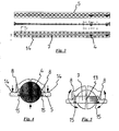
- FIG. 3 shows the strip-shaped ball cage 5 in this illustration only two arranged in the through holes 7 balls 4. It goes without saying that in a fully assembled linear guide system in each or at least most of the through holes 7, a ball 4 is provided.
- FIG. 4 shows an enlarged cross-sectional view of the ball cage 5 according to FIG. 3 along the section line CC.
- the conical taper of the inner diameter of the through hole 7 and the holding means 15 designed as elastic webs can be seen.
- the conically tapered wall surface 8 of the through hole lies above the center plane of the ball at this and the holding means 15 are below the median plane of the ball at this and thus secure the ball against falling out of the through hole. 7
- knob-shaped elevations 14 are arranged on the ball cage 5 in the vicinity of the side edges.
- FIG. 3 Lower illustration, shows that the knob-shaped elevations 14 are arranged in rows one behind the other and at regular intervals on the upper side of the ball cage 5. The knob-shaped elevations 14 reduce the contact surface of the ball cage in the grooves 6 and 6 'on the guide rail 1 and thus the frictional resistance.
- FIG. 5 shows a cross section through the ball cage 5 according to FIG. 3 along the section line DD.
- FIG. 5 shows essentially the same sectional view as FIG. 4 but without a ball inserted into the cut through hole 7.
- the ball cage 5 on the underside a Torsionsnut 13 (groove-shaped recess) which extends substantially over the entire length of the ball cage and by which the flexibility and elasticity of the ball cage is influenced transversely to its longitudinal extent.
- the width and depth of the Torsionsnut 13 thus the bias (biasing force) of the balls against the running surfaces 9 and 9 'of the guide rail 1 can be varied or adjusted.
- a Torsionsnut although this passes through the through holes of the ball cage and in the through holes actually no more groove represents.
- one could also speak of many individual (small) torsion grooves which extend in the areas between adjacent passage openings in the longitudinal direction of the ball cage.
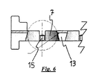
- FIG. 6 shows a section through the strip-shaped ball cage according to FIG. 3 along the section line FF.
- the end portions of the strip-shaped ball cage upstanding end stops which are designed so that the carriage can not be moved across one end of the ball cage away.
Description
Die vorliegende Erfindung betrifft ein Linearführungssystem mit einer Führungsschiene und einem daran über wenigstens zwei Kugellager verfahrbar geführten Schlitten, wobei die Kugellager jeweils mehrere Kugeln und einen streifenförmigen Kugelkäfig umfassen und die Führungsschiene Laufflächen und der Schlitten Laufflächen für das Abwälzen der Kugeln der Kugellager aufweisen.The present invention relates to a linear guide system with a guide rail and a guided over at least two ball bearings guided carriage, wherein the ball bearings each comprise a plurality of balls and a strip-shaped ball cage and the guide rail running surfaces and the carriage treads for rolling the balls of the ball bearings.
Linearführungssysteme lassen sich in den verschiedensten Bereichen einsetzen. Im Automobilbau werden Linearführungssysteme mit hoher Belastbarkeit u.a. für Fahrzeugschiebetüren, Ladeböden, längsverstellbare Konsolen im Fahrzeuginnenraum und andere Einrichtungen verwendet.Linear guidance systems can be used in a wide variety of areas. In the automotive industry, linear guide systems with high load capacity are used. used for vehicle sliding doors, load floors, longitudinally adjustable consoles in the vehicle interior and other facilities.
Im Bereich der Fahrzeugschiebetüren werden aus Stabilitätsgründen häufig Führungsschienen an der Außenseite der Karosserie montiert, an denen die Schiebetüren geführt werden. Eine solche Montage an der Außenseite der Karosserie gewährleistet zwar eine hohe Stabilität des Führungssystems unter der Belastung des Gewichts der Schiebetür, jedoch sind die auf der Außenseite der Karosserie montierten Führungsschienen bei geschlossener Schiebetür sichtbar und stören die Optik erheblich. Darüber hinaus sind diese Führungsschienen aufgrund ihrer Montage auf der Außenseite des Fahrzeugs ständig den äußeren Witterungsbedingungen ausgesetzt und korrodieren daher schneller als innen montierte Führungssysteme oder erfordern einen erheblich höheren Korrosionsschutz. Zudem sind solche Führungsschienen profiliert, so daß sich Schmutz aus der Umgebung an und in den Schienen schnell ansammelt und die Laufeigenschaften des Führungssystems dadurch sehr schnell verschlechtert werden.In the field of vehicle sliding doors, for reasons of stability, guide rails are frequently mounted on the outside of the body on which the sliding doors are guided. Although such an assembly on the outside of the body ensures high stability of the guide system under the burden of the weight of the sliding door, however, mounted on the outside of the body guide rails are visible with the sliding door closed and disturb the appearance considerably. In addition, due to their mounting on the outside of the vehicle, these guide rails are constantly exposed to external weather conditions and therefore corrode faster than guide systems mounted inside or require significantly higher corrosion protection. In addition, such guide rails are profiled so that dirt from the environment on and in the rails quickly accumulates and the running characteristics of the guide system are thereby deteriorated very quickly.
Eine Schiebetür für Kraftfahrzeuge mit einer auf der Innenseite der Tür montierten Führungsschiene, bei der einige der vorgenannten Nachteile von auf der Außenseite der Karosserie montierten Führungsschienen überwunden werden, offenbart die
Die
Die Aufgabe der vorliegenden Erfindung bestand darin, ein Linearführungssystem bereitzustellen, das hohe Lasten tragen kann, eine geringe Geräuschentwicklung aufweist, eine kompakte Bauweise besitzt, große Verfahrwege zuläßt und verhältnismäßig preiswert herzustellen ist. Eine weitere Aufgabe der Erfindung bestand darin, ein Linearführungssystem für Fahrzeugschiebetüren, Ladeböden, längsverstellbare Konsolen im Fahrzeuginnenraum etc. mit den vorgenannten Eigenschaften zu schaffen.The object of the present invention was to provide a linear guide system that can carry high loads, has a low noise, has a compact design, allows large travel paths and is relatively inexpensive to manufacture. Another object of the invention was to provide a linear guide system for vehicle sliding doors, load floors, longitudinally adjustable consoles in the vehicle interior, etc. with the aforementioned properties.
Gelöst wird diese Aufgabe erfindungsgemäß durch ein Linearführungssystem der eingangs genannten Art mit den Merkmalen des Anspruchs 1.This object is achieved according to the invention by a linear guide system of the aforementioned type with the features of
Bei dem streifenförmigen Kugelkäfig des erfindungsgemäßen Linearführungssystems sitzen die Kugeln in den Durchgangsöffnungen und sind gegen ein Herausfallen nach oben, d. h. in der Richtung von einer Lauffläche der Führungsschiene hin zu der zugehörigen Lauffläche des Schlittens, gesichert, indem entweder der Innendurchmesser der Durchgangsöffnungen konisch auf einen Innendurchmesser verjüngt ist, der kleiner ist als der Durchmesser der Kugeln, oder indem er durch Begrenzungsmittel auf einen Innendurchmesser eingeengt ist, der kleiner ist als der Durchmesser der Kugeln.In the strip-shaped ball cage of the linear guide system according to the invention, the balls sit in the passage openings and are against falling upwards, d. H. in the direction from a running surface of the guide rail to the associated running surface of the carriage, secured by either the inner diameter of the through holes is tapered conically to an inner diameter which is smaller than the diameter of the balls, or by being restricted by limiting means to an inner diameter which is smaller than the diameter of the balls.
In einer bevorzugten Ausführungsform sind an den Durchgangsöffnungen des Kugelkäfigs elastisch verformbare Haltemittel vorgesehen, welche so ausgebildet sind, daß sie die Kugeln gegen ein Herausfallen aus den Durchgangsöffnungen in Richtung der unter dem Kugelkäfig angeordneten Lauffläche der Führungsschiene sichern, wenn die Kugeln nicht an der Lauffläche anliegen. Da die Kugeln von dem Kugelkäfig und den oberen Haltemitteln mit einer Vorspannung gegen die Laufflächen der Führungsschiene gehalten werden, kommt diese Sicherung nur zum Tragen, wenn die Kugeln nicht an der Lauffläche anliegen, z. B. bei der Montage und Lagerung des Kugelkäfigs.In a preferred embodiment, elastically deformable retaining means are provided at the through openings of the ball cage, which are designed so that they secure the balls against falling out of the through holes in the direction of the ball cage arranged under the running surface of the guide rail, if the balls do not rest on the tread , Since the balls are held by the ball cage and the upper holding means with a bias against the running surfaces of the guide rail, this backup comes only to bear, if the balls do not rest against the tread, z. B. during assembly and storage of the ball cage.
Bevorzugt sind die elastisch verformbaren Haltemittel in Richtung der unter dem Kugelkäfig angeordneten Lauffläche als elastisch zur Mitte der Durchgangsöffnungen hin vorgespannte Stege ausgebildet. Da diese Haltemittel nur benötigt werden, wenn die Kugeln nicht an der Lauffläche anliegen, genügt es, wenn ein oder zwei solcher Stege an jeder Durchgangsöffnung vorgesehen ist, um die Kugel in der Durchgangsöffnung gegen ein Herausfallen zu sichern. Selbstverständlich können auch mehrere solcher Stege vorgesehen sein. Bei der Montage des Kugelkäfigs, nämlich beim Einsetzen der Kugeln in die Durchgangsöffnungen des Kugelkäfigs, werden die Kugeln von unten in den Kugelkäfig eingesetzt, wobei die Haltemittel bzw. Stege kurzzeitig auseinandergedrückt werden, damit eine Kugel eingesetzt werden kann.Preferably, the elastically deformable holding means in the direction of the arranged under the ball cage tread are formed as elastically biased to the center of the through holes webs. Since these holding means are required only when the balls do not abut the tread, it is sufficient if one or two such webs is provided at each through hole to secure the ball in the through hole against falling out. Of course, several such webs may be provided. When mounting the ball cage, namely when inserting the balls in the through holes of the ball cage, the balls are inserted from below into the ball cage, the holding means or webs are briefly pressed apart so that a ball can be used.
Der erfindungsgemäße streifenförmige Kugelkäfig ist einfach und preiswert herzustellen und an der Führungsschiene zu montieren und bietet gute Laufeigenschaften für das Linearführungssystem. Die Länge des Kugelkäfigs und die Anzahl der darin angeordneten Kugeln und Durchgangsöffnungen hängt wesentlich von der Gesamtlänge des Führungssystems und des Verfahrwegs ab, jedoch auch von der geforderten Belastbarkeit des Linearführungssystems, der gewünschten Haptik und Laufruhe.The strip-shaped ball cage according to the invention is simple and inexpensive to manufacture and to mount on the guide rail and offers good running properties for the linear guide system. The length of the ball cage and the number of balls and through holes arranged therein depends essentially on the overall length of the guide system and the travel, but also on the required load capacity of the linear guide system, the desired feel and smoothness.
Ein weiteres wesentliches Merkmal des erfindungsgemäßen Linearführungssystem ist, daß die Kugeln von dem Kugelkäfig mit einer Vorspannung gegen die Laufflächen der Führungsschiene gehalten werden. Dies gewährleistet, daß die Kugeln stets an den Laufflächen der Führungsschiene anliegen, wodurch ein Klappern und störende Geräuschentwicklung des Kugellagers, z.B. bei Vibrationen, vermieden werden, und zwar auch bei den Kugeln, die gerade nicht unter Belastung zwischen der Laufschiene und dem Schlitten stehen. Um die Vorspannung zu gewährleisten, ist der Kugelkäfig elastisch verformbar bzw. flexibel ausgebildet.Another essential feature of the linear guide system according to the invention is that the balls are held by the ball cage with a bias against the running surfaces of the guide rail. This ensures that the balls are always in contact with the running surfaces of the guide rail, whereby a rattling and disturbing noise of the ball bearing, e.g. in vibration, be avoided, even in the balls that are not under load between the running rail and the carriage. To ensure the bias, the ball cage is elastically deformable or flexible.
In einer bevorzugten Ausführungsform des erfindungsgemäßen Linearführungssystems greifen die Seitenkanten in der Längserstreckung des streifenförmigen Kugelkäfigs in zwei sich in der Längserstreckung der Führungsschiene einander gegenüberliegenden Nuten für die Befestigung des Kugelkäfigs an der Führungsschiene ein. Für diesen Zweck sind neben den Laufflächen der Führungsschiene zwei mit ihren Öffnungen einander zugewandte Nuten vorgesehen. In diese Nuten werden die Seitenkanten des streifenförmigen Kugelkäfigs eingeführt. Dabei ist die Anordnung der Nuten so gewählt, daß der Kugelkäfig bei der Befestigung quer zu seiner Längsachse leicht verbogen wird und aufgrund seiner Flexibilität bzw. Elastizität die Kugeln stets mit einer Vorspannung gegen die Lauffläche der Führungsschiene drückt. Zweckmäßigerweise ist der streifenförmige Kugelkäfig daher aus einem flexiblen, elastischen Material, vorzugsweise Kunststoff, hergestellt. Er kann jedoch auch aus Metall, beispielsweise Stahl oder Edelstahl hergestellt sein.In a preferred embodiment of the linear guide system according to the invention, the side edges engage in the longitudinal extent of the strip-shaped ball cage in two mutually opposite in the longitudinal extent of the guide rail grooves for the attachment of the ball cage on the guide rail. For this purpose, in addition to the running surfaces of the guide rail two provided with their openings facing each other grooves. In these grooves, the side edges of the strip-shaped ball cage are introduced. In this case, the arrangement of the grooves is chosen so that the ball cage is slightly bent during attachment transversely to its longitudinal axis and due to its flexibility or elasticity, the balls always presses with a bias against the tread of the guide rail. Conveniently, the strip-shaped ball cage is therefore made of a flexible, elastic material, preferably plastic. However, it can also be made of metal, for example steel or stainless steel.
In einer ganz besonders bevorzugten Ausführungsform des erfindungsgemäßen Linearführungssystems weist die Führungsschiene auf zwei einander gegenüberliegenden Seiten jeweils eine Lauffläche und ein Kugellager auf. Alternativ können an der Führungsschiene jedoch auch mehr als zwei Laufflächen und zwei Kugellager vorgesehen sein, beispielsweise zwei Laufflächen und zwei Kugellager auf jeder Seite der Führungsschiene. Für die meisten Anwendungen ist es jedoch ausreichend, wenn auf jeder der gegenüberliegenden Seiten der Führungsschiene jeweils genau eine Lauffläche und ein Kugellager vorgesehen sind.In a very particularly preferred embodiment of the linear guide system according to the invention, the guide rail on two opposite sides in each case a running surface and a ball bearing. Alternatively, however, more than two running surfaces and two ball bearings may be provided on the guide rail, for example two running surfaces and two ball bearings on each side of the guide rail. For most applications, however, it is sufficient if exactly one tread and one ball bearing are provided on each of the opposite sides of the guide rail.
Die Gesamtlänge des Linearführungssystems wird im wesentlichen durch die Länge der Führungsschiene vorgegeben. Der auf der Führungsschiene verfahrbar geführte Schlitten ist erheblich kürzer als die Führungsschiene. Der maximale Verfahrweg wird durch die Gesamtlänge der Führungsschiene und das Verhältnis der Länge des Schlittens zu der Länge der Führungsschiene bestimmt. Bei gegebener Länge der Führungsschiene ist der maximal mögliche Verfahrweg für einen an dem Schlitten befestigten Gegenstand umso länger je kürzer der Schlitten ist. Die Auswahl der Länge des an der Führungsschiene verfahrbar geführten Schlittens bestimmt sich jedoch nicht nur nach dem gewünschten Verfahrweg, sondern auch nach der erforderlichen Belastbarkeit und Stabilität des Linearführungssystems. Je länger der Schlitten ist, desto höher sind Belastbarkeit, Laufstabilität und Laufruhe, da bei gleich ausgestaltetem Kugellager ein längerer Schlitten gleichzeitig an mehr Kugeln abgerollt wird als ein kürzerer Schlitten.The total length of the linear guide system is essentially determined by the length of the guide rail. The guided on the guide rail carriage is considerably shorter than the guide rail. The maximum travel is determined by the overall length of the guide rail and the ratio of the length of the carriage to the length of the guide rail. For a given length of the guide rail, the maximum possible travel for an object attached to the carriage is the longer the shorter the carriage. However, the selection of the length of the guided on the guide rail carriage guided determines not only the desired travel, but also the required load capacity and stability of the linear guide system. The longer the carriage is, the higher the load capacity, running stability and smoothness, since the same design ball bearing a longer carriage is simultaneously unrolled to more balls than a shorter carriage.
Zweckmäßigerweise umfaßt der Schlitten ein im Querschnitt im wesentlichen C-förmiges Profil, dessen jeweilige Endabschnitte Laufflächen aufweisen und die Führungsschiene im Bereich der Kugellager umgreifen. In einer besonders bevorzugten Ausführungsform des erfindungsgemäßen Linearführungssystems weist der Schlitten weiterhin eine Platte auf, die sich zwischen den Endabschnitten des im wesentlichen C-förmigen Profils des Schlittens erstreckt und mit den Endabschnitten unlösbar oder lösbar, vorzugsweise unlösbar, besonders bevorzugt mittels einer Schweißverbindung, verbunden ist. Das C-förmige Profil und die an dessen Endabschnitten befestigte Platte umschließen die Führungsschiene somit vollständig wie ein rohrförmig geschlossenes Profil. Durch das Schließen des C-förmigen Profils des Schlittens zu einem rohrförmigen Profil mittels der mit den Endabschnitten des C-förmigen Profils verbundenen Platte wird ein sehr hoher Lastwert und eine außerordentlich gute Verwindungsstabilität des Linearführungssystems erzielt. Die Verwendung einer Platte für die Verbindung der jeweiligen Endabschnitte des C-förmigen Profils des Schlittens hat den weiteren Vorteil, daß bei der Herstellung des Linearführungssystems auftretende Toleranzen der Einzelteile beim Verbinden der Platte mit den Endabschnitten des C-förmigen Profils ausgeglichen werden können. Beim Verbinden der Platte mit den Endabschnitten des C-förmigen Profils kann das C-förmige Profil zum Ausgleich von Toleranzen mehr oder weniger stark zusammengedrückt werden und verbleibt nach dem Verbinden der Platte mit den Endabschnitten in dieser Lage. Hierdurch können sowohl Toleranzen bei der Herstellung des C-förmigen Profils des Schlittens als auch Toleranzen bei der Herstellung der Führungsschiene ausgeglichen werden.Conveniently, the carriage comprises a cross-sectionally substantially C-shaped profile whose respective end portions have running surfaces and engage around the guide rail in the region of the ball bearings. In a particularly preferred embodiment of the linear guide system according to the invention, the carriage further comprises a plate which extends between the end portions of the substantially C-shaped profile of the carriage and with the end portions insoluble or releasably, preferably non-detachably, more preferably by means of a welded joint is connected , The C-shaped profile and the plate attached to its end portions thus completely surround the guide rail like a tubular closed profile. By closing the C-shaped profile of the carriage into a tubular profile by means of the plate connected to the end portions of the C-shaped profile, a very high load value and an extremely good torsional stability of the linear guide system achieved. The use of a plate for the connection of the respective end portions of the C-shaped profile of the carriage has the further advantage that occurring in the manufacture of the linear guide system tolerances of the individual parts when connecting the plate with the end portions of the C-shaped profile can be compensated. When connecting the plate to the end portions of the C-shaped profile, the C-shaped profile can be compressed more or less to compensate for tolerances and remains after connecting the plate to the end portions in this position. As a result, both tolerances in the production of the C-shaped profile of the carriage and tolerances in the production of the guide rail can be compensated.
Im erfindungsgemäßen Linearführungssystem weist der streifenförmige Kugelkäfig in seiner Längserstreckung wenigstens abschnittsweise, vorzugsweise über seine gesamte Länge, wenigstens eine Torsionsnut (nutenförmige Ausnehmung) auf. Die wenigstens eine Torsionsnut ist auf der den Laufflächen der Führungsschiene zugewandten Seite des Kugelkäfigs angeordnet. Diese wenigstens eine Torsionsnut beeinflußt bzw. verändert die elastische Biegsamkeit des streifenförmigen Kugelkäfigs quer zu seiner Längsachse. Durch die Breite und Tiefe der wenigstens einen Torsionsnut kann die Vorspannkraft der Kugeln gegen die Laufflächen der Führungsschiene variiert bzw. eingestellt werden. Ein weiterer Vorteil der wenigstens einen Torsionsnut besteht darin, daß sie als Vorratsraum für einen bei Kugellagern üblicherweise verwendeten Schmierstoff dienen kann.In the linear guide system according to the invention, the strip-shaped ball cage in its longitudinal extent at least in sections, preferably over its entire length, at least one Torsionsnut (groove-shaped recess). The at least one Torsionsnut is arranged on the running surfaces of the guide rail side facing the ball cage. This at least one Torsionsnut influenced or changed the elastic flexibility of the strip-shaped ball cage transversely to its longitudinal axis. Due to the width and depth of the at least one Torsionsnut the biasing force of the balls can be varied or adjusted against the running surfaces of the guide rail. Another advantage of the at least one Torsionsnut is that it can serve as a reservoir for a lubricant commonly used in ball bearings.
In einer weiteren bevorzugten Ausführungsform des erfindungsgemäßen Linearführungssystems weist der streifenförmige Kugelkäfig auf der den Laufflächen der Führungsschiene abgewandten Seite mehrere in der Nähe der Seitenkanten in der Längsrichtung des Kugelkäfigs und in Reihe hintereinander angeordnete noppenförmige Erhebungen auf. Diese noppenförmigen Erhebungen haben mehrere Vorteile. Durch das Abrollen der Kugeln auf der Lauffläche der Führungsschiene beim Verfahren des Schlittens wird der gesamte Kugelkäfig in Längsrichtung der Führungsschiene ebenfalls mitverfahren bzw. -verschoben. Die noppenförmigen Erhebungen in der Nähe der Seitenkanten des streifenförmigen Kugelkäfigs verringern die Anlagefläche der Bereiche der Seitenkanten innerhalb der an der Führungsschiene zum Halten des Kugelkäfigs vorgesehenen Nuten und damit den Reibungswiderstand. Darüber hinaus sorgen die noppenförmigen Erhebungen für eine gute Verteilung von Schmierstoff, der zweckmäßigerweise in den Nuten an der Führungsschiene zum leichteren Verschieben des Kugelkäfigs vorgesehen ist.In a further preferred embodiment of the linear guide system according to the invention, the strip-shaped ball cage on the side facing away from the running surfaces of the guide rail on several in the vicinity of the side edges in the longitudinal direction of the ball cage and in series successively arranged knob-shaped elevations. These knob-shaped elevations have several advantages. By rolling the balls on the running surface of the guide rail during the process of the carriage, the entire ball cage in the longitudinal direction of the guide rail is also mitverfahren or -verschoben. The knob-shaped elevations near the side edges of the strip-shaped ball cage reduce the contact surface of the areas of the side edges within the provided on the guide rail for holding the ball cage grooves and thus the frictional resistance. In addition, the knob-shaped elevations ensure a good distribution of lubricant, which is expediently provided in the grooves on the guide rail for easier movement of the ball cage.
In einer weiteren bevorzugten Ausführungsform weit der streifenförmige Kugelkäfig an seinen beiden Endabschnitten Endanschläge auf, die so ausgebildet sind, daß der Schlitten nicht über ein Ende des Kugelkäfigs hinweg verfahren werden kann, sondern bei Erreichen eines Endes des Kugelkäfigs auf den Endanschlag trifft. Tritt dies ein und ist beim Verfahren des Schlittens noch nicht das Ende der Führungsschiene erreicht, so nimmt bzw. zieht der Schlitten den Kugelkäfig mit bis zum Ende des Verfahrweges. Durch die Endanschläge an den jeweiligen Enden des Kugelkäfigs wird gewährleistet, daß der Schlitten stets mit seiner vollen Länge über dem Kugelkäfig verbleibt und nicht über diesen hinaus verfahren wird. Dies verbessert Stabilität, Laufeigenschaften und Belastbarkeit des erfindungsgemäßen Führungssystems.In a further preferred embodiment, the strip-shaped ball cage at its two end portions on end stops, which are designed so that the carriage can not be moved across one end of the ball cage away, but strikes the end stop on reaching one end of the ball cage. If this occurs and if the end of the guide rail has not yet been reached when moving the carriage, then the carriage takes or pulls the ball cage with it to the end of the travel path. By the end stops at the respective ends of the ball cage ensures that the carriage always remains with its full length above the ball cage and is not moved beyond this. This improves stability, running properties and load capacity of the guide system according to the invention.
Weitere Vorteile, Merkmale und Ausgestaltungsformen des erfindungsgemäßen Linearführungssystems werden deutlich anhand der nachfolgenden Beschreibung einer bevorzugten Ausführungsform und der dazugehörigen Figuren.
Figur 1- zeigt ein erfindungsgemäßes Linearführungssystem in perspektivischer Ansicht schräg von oben.
Figur 2- zeigt ein erfindungsgemäßes Linearführungssystem im Querschnitt zu seiner Längserstreckung.
- Figur 3
- zeigt einen streifenförmigen Kugelkäfig des erfindungsgemäßen Linearführungssystems von unten, von der Seite und von oben.
Figur 4- zeigt einen Querschnitt durch den streifenförmigen Kugelkäfig gemäß
Figur 3 entlang der Schnittlinie C-C. Figur 5- zeigt einen Querschnitt durch den streifenförmigen Kugelkäfig gemäß
Figur 3 entlang der Schnittlinie D-D. Figur 6- zeigt einen Schnitt durch den streifenförmigen Kugelkäfig gemäß
Figur 3 entlang der Schnittlinie F-F.
- FIG. 1
- shows an inventive linear guide system in a perspective view obliquely from above.
- FIG. 2
- shows a linear guide system according to the invention in cross section to its longitudinal extent.
- FIG. 3
- shows a strip-shaped ball cage of the linear guide system according to the invention from below, from the side and from above.
- FIG. 4
- shows a cross section through the strip-shaped ball cage according to
FIG. 3 along the section line CC. - FIG. 5
- shows a cross section through the strip-shaped ball cage according to
FIG. 3 along the section line DD. - FIG. 6
- shows a section through the strip-shaped ball cage according to
FIG. 3 along the section line FF.
Des weiteren ist in
In
Wie in
- 11
- Führungsschieneguide rail
- 22
- Schlittencarriage
- 3, 3'3, 3 '
- Kugellagerball-bearing
- 44
- Kugelnroll
- 55
- Kugelkäfigball cage
- 6, 6'6, 6 '
- Nutengroove
- 77
- DurchgangsöffnungenThrough openings
- 88th
- verjüngte Wände der Durchgangsöffnungentapered walls of the passageways
- 9, 9'9, 9 '
-
Laufflächen der Führungsschiene 1Running surfaces of the
guide rail 1 - 10, 10'10, 10 '
- Laufflächen des C-förmigen Profils 11Running surfaces of the C-shaped profile 11th
- 1111
- C-förmiges ProfilC-shaped profile
- 11', 11"11 ', 11 "
- Endabschnitte des C-förmigen Profils 11End portions of the C-shaped profile eleventh
- 1212
- Platteplate
- 1313
- TorsionsnutTorsionsnut
- 1414
- noppenförmige Erhebungennap-shaped elevations
- 1515
- Haltemittelholding means
Claims (8)
- A linear guidance system comprising a guide rail (1) and a carriage (2) which is guided displaceably on the guide rail by way of at least two ball bearings (3, 3'), wherein the ball bearings respectively comprise a plurality of balls (4) and a strip-shaped ball cage (5) and the guide rail (1) has running surfaces (9, 9') and the carriage (2) has running surfaces (10, 10') for the rolling movement of the balls (4) of the ball bearings (3, 3'), wherein
the ball cage (5) has a plurality of substantially circular through openings (7) which are arranged in succession in a row and into which the balls (4) are inserted, wherein the inside diameter of the through openings tapers conically in the direction from a running surface (9, 9') of the guide rail to the associated running surface (10, 10') of the carriage (2) to an inside diameter or is constricted by limiting means to an inside diameter which is smaller than the diameter of the balls so that the balls are secured in the through openings (7) to prevent them from falling out of the through openings (7) in the direction of the running surface (10, 10') of the carriage,
the ball cage (5) is elastically deformable and is fixed to the guide rail (1),
the balls (4) are held by the ball cage (5) with a prestressing against the running surfaces (9, 9') of the guide rail,
characterized in that provided on the ball cage (5) in its longitudinal extent at least portion-wise and preferably over its entire length is at least one torsion groove (13) which is arranged on the side of the ball cage (5), that is towards the running surfaces (9, 9') of the guide rail (1). - A linear guidance system as set forth in claim 1 characterised in that provided at the through openings (7) of the ball cage (5) are elastically deformable holding means (15) which are of such a configuration that they secure the balls to prevent them from falling out of the through openings (7) in the direction of the running surface (9, 9') of the guide rail, arranged under the ball cage (5), when the balls (4) do not bear against the running surface (9, 9').
- A linear guidance system as set forth in one of the preceding claims characterised in that the side edges (5', 5") in the longitudinal extent of the strip-shaped ball cage (5) engage into two grooves (6, 6') disposed in mutually opposite relationship in the longitudinal extent of the guide rail (1) for securing the ball cage (5) to the guide rail.
- A linear guidance system as set forth in one of the preceding claims characterised in that the strip-shaped ball cage (5) is made from plastic material.
- A linear guidance system as set forth in one of the preceding claims characterised in that the guide rail (1) on two mutually opposite sides has respectively precisely one running surface (9, 9') and one ball bearing.
- A linear guidance system as set forth in one of the preceding claims characterised in that the carriage (2) includes a profile member (11) which is substantially C-shaped in crosssection and the respective end portions (11', 11 ") of which have running surfaces (10, 10') and embrace the guide rail (1) in the region of the ball bearings.
- A linear guidance system as set forth in claim 6 characterised in that the carriage (2) further includes a plate (12) which extends between the end portions (11', 11") of the substantially C-shaped profile member (11) of the carriage (2) and is connected to the end portions (11', 11") non-releasably or releasably, preferably non-releasably, particularly preferably by means of a welded connection.
- A linear guidance system as set forth in one of the preceding claims characterised in that the strip-shaped ball cage (5), on the side remote from the running surfaces (9, 9') of the guide rail (1), has a plurality of knob-shaped raised portions (14) arranged in succession in a row and in the proximity of the side edges in the longitudinal extent of the ball cage (5).
Applications Claiming Priority (2)
| Application Number | Priority Date | Filing Date | Title |
|---|---|---|---|
| DE102007040230 | 2007-08-25 | ||
| PCT/EP2008/061027 WO2009027342A1 (en) | 2007-08-25 | 2008-08-22 | Linear guidance system |
Publications (2)
| Publication Number | Publication Date |
|---|---|
| EP2183493A1 EP2183493A1 (en) | 2010-05-12 |
| EP2183493B1 true EP2183493B1 (en) | 2015-06-17 |
Family
ID=40469776
Family Applications (1)
| Application Number | Title | Priority Date | Filing Date |
|---|---|---|---|
| EP08787426.9A Active EP2183493B1 (en) | 2007-08-25 | 2008-08-22 | Linear guidance system |
Country Status (5)
| Country | Link |
|---|---|
| US (1) | US8240916B2 (en) |
| EP (1) | EP2183493B1 (en) |
| JP (1) | JP5590399B2 (en) |
| CN (1) | CN101821521B (en) |
| WO (1) | WO2009027342A1 (en) |
Families Citing this family (5)
| Publication number | Priority date | Publication date | Assignee | Title |
|---|---|---|---|---|
| EP2863774B1 (en) | 2012-06-25 | 2017-02-22 | Paul Hettich GmbH & Co. KG | Pull-out guide device for furniture parts that are movable relative to one another comprising a roller bearing device |
| DE102015000019A1 (en) * | 2015-01-07 | 2016-07-07 | Trw Automotive Gmbh | Gurtschlossbringer |
| CN107781297A (en) * | 2016-08-31 | 2018-03-09 | 泰州市创新电子有限公司 | A kind of outer rail is the ball slide rail of cladding shell type |
| JP2019082037A (en) * | 2017-10-30 | 2019-05-30 | 株式会社Lixil | Door roller |
| CN109363524B (en) * | 2018-11-16 | 2024-02-27 | 广东新宝电器股份有限公司 | Sliding door mechanism for electric oven and electric oven |
Family Cites Families (24)
| Publication number | Priority date | Publication date | Assignee | Title |
|---|---|---|---|---|
| GB738486A (en) * | 1952-01-02 | 1955-10-12 | Ronald Robert Stewart Charteri | Improvements in or relating to supports for closure members, such as doors for vehicles |
| US2812222A (en) * | 1954-06-18 | 1957-11-05 | Grant Pulley & Hardware Corp | Permanent ball retainer for sliding members |
| US3113807A (en) * | 1961-10-12 | 1963-12-10 | Automation Gages Inc | Ball slide |
| US3145065A (en) * | 1961-12-26 | 1964-08-18 | Bausch & Lomb | Bearing assembly |
| US3801166A (en) * | 1973-01-05 | 1974-04-02 | Fall H | Drawer slide bearing retainer lock |
| DE2851305A1 (en) * | 1978-11-27 | 1980-06-04 | Hettich Paul & Co | DRAWER GUIDE FOR DRAWERS |
| JPS616421U (en) * | 1984-06-18 | 1986-01-16 | トヨタ車体株式会社 | Guide rail structure of vehicle sliding door |
| US4655613A (en) * | 1984-07-10 | 1987-04-07 | Nippon Thompson Co., Ltd. | Linear motion rolling contact bearing assembly |
| US4629260A (en) * | 1985-05-07 | 1986-12-16 | Nippon Thompson Co., Ltd. | Piggyback rolling-contact bearing assembly |
| GB2213211B (en) | 1985-07-06 | 1990-01-24 | Firsteel Metal Prod | Bearing cages |
| GB2233215B (en) * | 1989-06-14 | 1992-06-10 | Sugatsune Kogyo | Slide rail assembly |
| US4991981A (en) * | 1990-05-14 | 1991-02-12 | Waterloo Metal Stampings Ltd. | Ball bearing retainer for drawer slides |
| DE4025011A1 (en) | 1990-08-07 | 1992-02-13 | Werner Dipl Ing Jacob | BALL GUIDE |
| US5106207A (en) * | 1991-03-25 | 1992-04-21 | Automation Gages, Inc. | Ball slide designed for extended travel |
| US5201584A (en) * | 1991-09-18 | 1993-04-13 | At&T Bell Laboratories | Mechanism for preloading linear bearing slides |
| TW205587B (en) | 1991-09-18 | 1993-05-11 | American Telephone & Telegraph | |
| JP2568320Y2 (en) * | 1992-07-31 | 1998-04-08 | 日本トムソン株式会社 | Linear motion rolling guide unit |
| DE4314115A1 (en) | 1993-04-29 | 1994-11-03 | Opel Adam Ag | Sliding door, in particular for motor vehicles |
| DE29604922U1 (en) | 1996-03-16 | 1996-05-30 | Reme Moebelbeschlaege Gmbh | Pull-out rail |
| US6105920A (en) * | 1996-06-06 | 2000-08-22 | Lear Corporation | Vehicle power seat adjuster with hidden floor mount |
| US6655763B2 (en) * | 2000-12-22 | 2003-12-02 | Jonathan Engineered Solutions | Controller for a quick disconnect slide assembly |
| JP2003065350A (en) * | 2001-08-28 | 2003-03-05 | Ntn Corp | Tripod type constant velocity universal coupling |
| CN2911303Y (en) * | 2006-03-23 | 2007-06-13 | 晟铭电子科技股份有限公司 | Slidway structure having two-way retaining balls |
| JP5215131B2 (en) * | 2008-10-31 | 2013-06-19 | 京セラドキュメントソリューションズ株式会社 | Image forming apparatus and photosensitive member rotation synchronization method |
-
2008
- 2008-08-22 CN CN200880106143.3A patent/CN101821521B/en active Active
- 2008-08-22 WO PCT/EP2008/061027 patent/WO2009027342A1/en active Application Filing
- 2008-08-22 EP EP08787426.9A patent/EP2183493B1/en active Active
- 2008-08-22 US US12/733,343 patent/US8240916B2/en active Active
- 2008-08-22 JP JP2010521440A patent/JP5590399B2/en active Active
Also Published As
| Publication number | Publication date |
|---|---|
| EP2183493A1 (en) | 2010-05-12 |
| WO2009027342A1 (en) | 2009-03-05 |
| JP5590399B2 (en) | 2014-09-17 |
| JP2010536644A (en) | 2010-12-02 |
| US8240916B2 (en) | 2012-08-14 |
| CN101821521A (en) | 2010-09-01 |
| CN101821521B (en) | 2013-06-19 |
| US20100316311A1 (en) | 2010-12-16 |
Similar Documents
| Publication | Publication Date | Title |
|---|---|---|
| EP2183494B1 (en) | Linear guidance system comprising a hollow-profile rail | |
| DE102012100287B4 (en) | vehicle seat | |
| EP2694328B1 (en) | Linear guide | |
| EP2405786B1 (en) | Pull-out guide | |
| EP2593686B1 (en) | Vehicle seat with a longitudinal adjustment device comprising a rail guide | |
| DE102008023246A1 (en) | Falling catch and motor force setting | |
| EP2183493B1 (en) | Linear guidance system | |
| WO2014166833A1 (en) | Longitudinal adjuster for a vehicle seat, and vehicle seat | |
| EP2705979B1 (en) | Overload protection | |
| WO2015032655A1 (en) | Winding device for a roller blind arrangement, roller blind arrangement and roof arrangement | |
| DE10249698A1 (en) | Slide rail system, in particular for motor vehicle seats | |
| EP2168457A2 (en) | Pull-out guide for a pull-out furniture section | |
| EP2979906A1 (en) | Shading device for a transparent surface of a motor vehicle | |
| DE102020203210A1 (en) | Steering column for a motor vehicle | |
| WO2000035705A1 (en) | Rail for guiding slide rails of automobile components and method for producing the same | |
| EP2215928A2 (en) | Guide rail of a furniture pull-out guide | |
| EP3724526B1 (en) | Telescopic rail | |
| EP3233563A1 (en) | Cover for a rail pair of a longitudinally adjustable vehicle seat and rail pair | |
| DE102009017173B4 (en) | Linear carriage and linear guide | |
| EP0779174A2 (en) | Longitudinal adjustment of a seat | |
| DE102009017174B4 (en) | Linear carriage, linear guide and method for mounting a linear carriage | |
| WO2014202272A1 (en) | Guide shoe for an elevator | |
| DE102004001568B4 (en) | telescopic rail | |
| EP3085281B1 (en) | Sliding element for displaceable storage of a curtain or a tarpaulin | |
| EP3565982B1 (en) | Rolling body cage for a telescopic rail or a linear guide |
Legal Events
| Date | Code | Title | Description |
|---|---|---|---|
| PUAI | Public reference made under article 153(3) epc to a published international application that has entered the european phase |
Free format text: ORIGINAL CODE: 0009012 |
|
| 17P | Request for examination filed |
Effective date: 20100219 |
|
| AK | Designated contracting states |
Kind code of ref document: A1 Designated state(s): AT BE BG CH CY CZ DE DK EE ES FI FR GB GR HR HU IE IS IT LI LT LU LV MC MT NL NO PL PT RO SE SI SK TR |
|
| AX | Request for extension of the european patent |
Extension state: AL BA MK RS |
|
| DAX | Request for extension of the european patent (deleted) | ||
| 17Q | First examination report despatched |
Effective date: 20110518 |
|
| GRAP | Despatch of communication of intention to grant a patent |
Free format text: ORIGINAL CODE: EPIDOSNIGR1 |
|
| INTG | Intention to grant announced |
Effective date: 20150205 |
|
| GRAS | Grant fee paid |
Free format text: ORIGINAL CODE: EPIDOSNIGR3 |
|
| GRAA | (expected) grant |
Free format text: ORIGINAL CODE: 0009210 |
|
| AK | Designated contracting states |
Kind code of ref document: B1 Designated state(s): AT BE BG CH CY CZ DE DK EE ES FI FR GB GR HR HU IE IS IT LI LT LU LV MC MT NL NO PL PT RO SE SI SK TR |
|
| REG | Reference to a national code |
Ref country code: GB Ref legal event code: FG4D Free format text: NOT ENGLISH |
|
| REG | Reference to a national code |
Ref country code: CH Ref legal event code: EP |
|
| REG | Reference to a national code |
Ref country code: AT Ref legal event code: REF Ref document number: 732107 Country of ref document: AT Kind code of ref document: T Effective date: 20150715 |
|
| REG | Reference to a national code |
Ref country code: IE Ref legal event code: FG4D Free format text: LANGUAGE OF EP DOCUMENT: GERMAN |
|
| REG | Reference to a national code |
Ref country code: DE Ref legal event code: R096 Ref document number: 502008013064 Country of ref document: DE |
|
| PG25 | Lapsed in a contracting state [announced via postgrant information from national office to epo] |
Ref country code: HR Free format text: LAPSE BECAUSE OF FAILURE TO SUBMIT A TRANSLATION OF THE DESCRIPTION OR TO PAY THE FEE WITHIN THE PRESCRIBED TIME-LIMIT Effective date: 20150617 Ref country code: FI Free format text: LAPSE BECAUSE OF FAILURE TO SUBMIT A TRANSLATION OF THE DESCRIPTION OR TO PAY THE FEE WITHIN THE PRESCRIBED TIME-LIMIT Effective date: 20150617 Ref country code: NO Free format text: LAPSE BECAUSE OF FAILURE TO SUBMIT A TRANSLATION OF THE DESCRIPTION OR TO PAY THE FEE WITHIN THE PRESCRIBED TIME-LIMIT Effective date: 20150917 Ref country code: LT Free format text: LAPSE BECAUSE OF FAILURE TO SUBMIT A TRANSLATION OF THE DESCRIPTION OR TO PAY THE FEE WITHIN THE PRESCRIBED TIME-LIMIT Effective date: 20150617 |
|
| REG | Reference to a national code |
Ref country code: LT Ref legal event code: MG4D Ref country code: NL Ref legal event code: MP Effective date: 20150617 |
|
| PG25 | Lapsed in a contracting state [announced via postgrant information from national office to epo] |
Ref country code: GR Free format text: LAPSE BECAUSE OF FAILURE TO SUBMIT A TRANSLATION OF THE DESCRIPTION OR TO PAY THE FEE WITHIN THE PRESCRIBED TIME-LIMIT Effective date: 20150918 Ref country code: BG Free format text: LAPSE BECAUSE OF FAILURE TO SUBMIT A TRANSLATION OF THE DESCRIPTION OR TO PAY THE FEE WITHIN THE PRESCRIBED TIME-LIMIT Effective date: 20150917 Ref country code: LV Free format text: LAPSE BECAUSE OF FAILURE TO SUBMIT A TRANSLATION OF THE DESCRIPTION OR TO PAY THE FEE WITHIN THE PRESCRIBED TIME-LIMIT Effective date: 20150617 |
|
| PG25 | Lapsed in a contracting state [announced via postgrant information from national office to epo] |
Ref country code: EE Free format text: LAPSE BECAUSE OF FAILURE TO SUBMIT A TRANSLATION OF THE DESCRIPTION OR TO PAY THE FEE WITHIN THE PRESCRIBED TIME-LIMIT Effective date: 20150617 |
|
| PG25 | Lapsed in a contracting state [announced via postgrant information from national office to epo] |
Ref country code: PT Free format text: LAPSE BECAUSE OF FAILURE TO SUBMIT A TRANSLATION OF THE DESCRIPTION OR TO PAY THE FEE WITHIN THE PRESCRIBED TIME-LIMIT Effective date: 20151019 Ref country code: IS Free format text: LAPSE BECAUSE OF FAILURE TO SUBMIT A TRANSLATION OF THE DESCRIPTION OR TO PAY THE FEE WITHIN THE PRESCRIBED TIME-LIMIT Effective date: 20151017 Ref country code: PL Free format text: LAPSE BECAUSE OF FAILURE TO SUBMIT A TRANSLATION OF THE DESCRIPTION OR TO PAY THE FEE WITHIN THE PRESCRIBED TIME-LIMIT Effective date: 20150617 Ref country code: ES Free format text: LAPSE BECAUSE OF FAILURE TO SUBMIT A TRANSLATION OF THE DESCRIPTION OR TO PAY THE FEE WITHIN THE PRESCRIBED TIME-LIMIT Effective date: 20150617 Ref country code: CZ Free format text: LAPSE BECAUSE OF FAILURE TO SUBMIT A TRANSLATION OF THE DESCRIPTION OR TO PAY THE FEE WITHIN THE PRESCRIBED TIME-LIMIT Effective date: 20150617 Ref country code: SK Free format text: LAPSE BECAUSE OF FAILURE TO SUBMIT A TRANSLATION OF THE DESCRIPTION OR TO PAY THE FEE WITHIN THE PRESCRIBED TIME-LIMIT Effective date: 20150617 Ref country code: RO Free format text: LAPSE BECAUSE OF NON-PAYMENT OF DUE FEES Effective date: 20150617 |
|
| REG | Reference to a national code |
Ref country code: DE Ref legal event code: R097 Ref document number: 502008013064 Country of ref document: DE |
|
| PG25 | Lapsed in a contracting state [announced via postgrant information from national office to epo] |
Ref country code: MC Free format text: LAPSE BECAUSE OF FAILURE TO SUBMIT A TRANSLATION OF THE DESCRIPTION OR TO PAY THE FEE WITHIN THE PRESCRIBED TIME-LIMIT Effective date: 20150617 Ref country code: LU Free format text: LAPSE BECAUSE OF FAILURE TO SUBMIT A TRANSLATION OF THE DESCRIPTION OR TO PAY THE FEE WITHIN THE PRESCRIBED TIME-LIMIT Effective date: 20150822 |
|
| REG | Reference to a national code |
Ref country code: CH Ref legal event code: PL |
|
| PLBE | No opposition filed within time limit |
Free format text: ORIGINAL CODE: 0009261 |
|
| STAA | Information on the status of an ep patent application or granted ep patent |
Free format text: STATUS: NO OPPOSITION FILED WITHIN TIME LIMIT |
|
| PG25 | Lapsed in a contracting state [announced via postgrant information from national office to epo] |
Ref country code: CH Free format text: LAPSE BECAUSE OF NON-PAYMENT OF DUE FEES Effective date: 20150831 Ref country code: DK Free format text: LAPSE BECAUSE OF FAILURE TO SUBMIT A TRANSLATION OF THE DESCRIPTION OR TO PAY THE FEE WITHIN THE PRESCRIBED TIME-LIMIT Effective date: 20150617 Ref country code: IT Free format text: LAPSE BECAUSE OF FAILURE TO SUBMIT A TRANSLATION OF THE DESCRIPTION OR TO PAY THE FEE WITHIN THE PRESCRIBED TIME-LIMIT Effective date: 20150617 Ref country code: LI Free format text: LAPSE BECAUSE OF NON-PAYMENT OF DUE FEES Effective date: 20150831 |
|
| 26N | No opposition filed |
Effective date: 20160318 |
|
| REG | Reference to a national code |
Ref country code: IE Ref legal event code: MM4A |
|
| PG25 | Lapsed in a contracting state [announced via postgrant information from national office to epo] |
Ref country code: IE Free format text: LAPSE BECAUSE OF NON-PAYMENT OF DUE FEES Effective date: 20150822 |
|
| REG | Reference to a national code |
Ref country code: FR Ref legal event code: PLFP Year of fee payment: 9 |
|
| PG25 | Lapsed in a contracting state [announced via postgrant information from national office to epo] |
Ref country code: SI Free format text: LAPSE BECAUSE OF FAILURE TO SUBMIT A TRANSLATION OF THE DESCRIPTION OR TO PAY THE FEE WITHIN THE PRESCRIBED TIME-LIMIT Effective date: 20150617 |
|
| REG | Reference to a national code |
Ref country code: AT Ref legal event code: MM01 Ref document number: 732107 Country of ref document: AT Kind code of ref document: T Effective date: 20150822 |
|
| PG25 | Lapsed in a contracting state [announced via postgrant information from national office to epo] |
Ref country code: AT Free format text: LAPSE BECAUSE OF NON-PAYMENT OF DUE FEES Effective date: 20150822 |
|
| PG25 | Lapsed in a contracting state [announced via postgrant information from national office to epo] |
Ref country code: MT Free format text: LAPSE BECAUSE OF FAILURE TO SUBMIT A TRANSLATION OF THE DESCRIPTION OR TO PAY THE FEE WITHIN THE PRESCRIBED TIME-LIMIT Effective date: 20150617 |
|
| PG25 | Lapsed in a contracting state [announced via postgrant information from national office to epo] |
Ref country code: HU Free format text: LAPSE BECAUSE OF FAILURE TO SUBMIT A TRANSLATION OF THE DESCRIPTION OR TO PAY THE FEE WITHIN THE PRESCRIBED TIME-LIMIT; INVALID AB INITIO Effective date: 20080822 |
|
| PG25 | Lapsed in a contracting state [announced via postgrant information from national office to epo] |
Ref country code: CY Free format text: LAPSE BECAUSE OF FAILURE TO SUBMIT A TRANSLATION OF THE DESCRIPTION OR TO PAY THE FEE WITHIN THE PRESCRIBED TIME-LIMIT Effective date: 20150617 Ref country code: NL Free format text: LAPSE BECAUSE OF FAILURE TO SUBMIT A TRANSLATION OF THE DESCRIPTION OR TO PAY THE FEE WITHIN THE PRESCRIBED TIME-LIMIT Effective date: 20150617 Ref country code: SE Free format text: LAPSE BECAUSE OF FAILURE TO SUBMIT A TRANSLATION OF THE DESCRIPTION OR TO PAY THE FEE WITHIN THE PRESCRIBED TIME-LIMIT Effective date: 20150617 |
|
| PG25 | Lapsed in a contracting state [announced via postgrant information from national office to epo] |
Ref country code: BE Free format text: LAPSE BECAUSE OF NON-PAYMENT OF DUE FEES Effective date: 20150831 |
|
| REG | Reference to a national code |
Ref country code: FR Ref legal event code: PLFP Year of fee payment: 10 |
|
| PG25 | Lapsed in a contracting state [announced via postgrant information from national office to epo] |
Ref country code: TR Free format text: LAPSE BECAUSE OF FAILURE TO SUBMIT A TRANSLATION OF THE DESCRIPTION OR TO PAY THE FEE WITHIN THE PRESCRIBED TIME-LIMIT Effective date: 20150617 |
|
| REG | Reference to a national code |
Ref country code: FR Ref legal event code: PLFP Year of fee payment: 11 |
|
| PGFP | Annual fee paid to national office [announced via postgrant information from national office to epo] |
Ref country code: GB Payment date: 20230822 Year of fee payment: 16 |
|
| PGFP | Annual fee paid to national office [announced via postgrant information from national office to epo] |
Ref country code: FR Payment date: 20230824 Year of fee payment: 16 Ref country code: DE Payment date: 20230822 Year of fee payment: 16 |