EP0779174A2 - Longitudinal adjustment of a seat - Google Patents
Longitudinal adjustment of a seat Download PDFInfo
- Publication number
- EP0779174A2 EP0779174A2 EP96120174A EP96120174A EP0779174A2 EP 0779174 A2 EP0779174 A2 EP 0779174A2 EP 96120174 A EP96120174 A EP 96120174A EP 96120174 A EP96120174 A EP 96120174A EP 0779174 A2 EP0779174 A2 EP 0779174A2
- Authority
- EP
- European Patent Office
- Prior art keywords
- seat
- adjustment according
- guide rail
- adjustment
- rolling
- Prior art date
- Legal status (The legal status is an assumption and is not a legal conclusion. Google has not performed a legal analysis and makes no representation as to the accuracy of the status listed.)
- Withdrawn
Links
Images
Classifications
-
- B—PERFORMING OPERATIONS; TRANSPORTING
- B60—VEHICLES IN GENERAL
- B60N—SEATS SPECIALLY ADAPTED FOR VEHICLES; VEHICLE PASSENGER ACCOMMODATION NOT OTHERWISE PROVIDED FOR
- B60N2/00—Seats specially adapted for vehicles; Arrangement or mounting of seats in vehicles
- B60N2/02—Seats specially adapted for vehicles; Arrangement or mounting of seats in vehicles the seat or part thereof being movable, e.g. adjustable
- B60N2/04—Seats specially adapted for vehicles; Arrangement or mounting of seats in vehicles the seat or part thereof being movable, e.g. adjustable the whole seat being movable
- B60N2/06—Seats specially adapted for vehicles; Arrangement or mounting of seats in vehicles the seat or part thereof being movable, e.g. adjustable the whole seat being movable slidable
- B60N2/07—Slide construction
- B60N2/0735—Position and orientation of the slide as a whole
- B60N2/0747—Position and orientation of the slide as a whole the opening of the cross section being oriented in a direction different from the vertical, e.g. transversal
-
- B—PERFORMING OPERATIONS; TRANSPORTING
- B60—VEHICLES IN GENERAL
- B60N—SEATS SPECIALLY ADAPTED FOR VEHICLES; VEHICLE PASSENGER ACCOMMODATION NOT OTHERWISE PROVIDED FOR
- B60N2/00—Seats specially adapted for vehicles; Arrangement or mounting of seats in vehicles
- B60N2/02—Seats specially adapted for vehicles; Arrangement or mounting of seats in vehicles the seat or part thereof being movable, e.g. adjustable
- B60N2/04—Seats specially adapted for vehicles; Arrangement or mounting of seats in vehicles the seat or part thereof being movable, e.g. adjustable the whole seat being movable
- B60N2/06—Seats specially adapted for vehicles; Arrangement or mounting of seats in vehicles the seat or part thereof being movable, e.g. adjustable the whole seat being movable slidable
- B60N2/07—Slide construction
- B60N2/0702—Slide construction characterised by its cross-section
- B60N2/072—Complex cross-section, e.g. obtained by extrusion
-
- B—PERFORMING OPERATIONS; TRANSPORTING
- B60—VEHICLES IN GENERAL
- B60N—SEATS SPECIALLY ADAPTED FOR VEHICLES; VEHICLE PASSENGER ACCOMMODATION NOT OTHERWISE PROVIDED FOR
- B60N2/00—Seats specially adapted for vehicles; Arrangement or mounting of seats in vehicles
- B60N2/02—Seats specially adapted for vehicles; Arrangement or mounting of seats in vehicles the seat or part thereof being movable, e.g. adjustable
- B60N2/04—Seats specially adapted for vehicles; Arrangement or mounting of seats in vehicles the seat or part thereof being movable, e.g. adjustable the whole seat being movable
- B60N2/06—Seats specially adapted for vehicles; Arrangement or mounting of seats in vehicles the seat or part thereof being movable, e.g. adjustable the whole seat being movable slidable
- B60N2/08—Seats specially adapted for vehicles; Arrangement or mounting of seats in vehicles the seat or part thereof being movable, e.g. adjustable the whole seat being movable slidable characterised by the locking device
- B60N2/0812—Location of the latch
- B60N2/0825—Location of the latch outside the rail
Definitions
- the invention relates to a device for compensating the manufacturing-related tolerances between a first and a second guide rail of a pair of guide rails for the longitudinal adjustment of motor vehicle seats.
- a device for compensating for play is known from DE 16 80 269 A1, in which guide rails provided on the sill side and on the tunnel side, in FIG. 2 also in the middle of the vehicle floor, enable the adjustment of a vehicle seat in the direction of the vehicle's longitudinal axis.
- the sill side is the side of the vehicle on which the vehicle doors are attached, the sill representing the lower area of the manhole.
- the tunnel usually runs in the middle of the vehicle interior in the direction of the vehicle's longitudinal axis and acts as the load-bearing backbone of the vehicle underbody, whereby the power transmission elements can be accommodated in it.
- a first running rail is designed in such a way that it does not permit displacement of the seat to the transverse vehicle axis, while a second running rail permits movements in the transverse vehicle axis.
- DE 39 20 077 A1 discloses a further device for compensating for the play resulting from construction tolerances.
- the tolerances that occur are compensated for by means of a bolt loaded with an energy accumulator, which interacts with a clamping device.
- DE 43 30 133 A1 describes a device for tolerance compensation in which, in particular, the tilting of the sliding elements should be prevented if there is too much play between the guides or if the guide rails do not run parallel to one another and the sliding elements moving therein.
- Each guide rail 1 and 2 of the device according to the invention consists of at least two metal profiles 1.1 and 1.2 or 2.1 and 2.2 nested with one another, the respective outer profile 1.1 or 2.1 made of comparatively thick-walled material serving to absorb the high loads which are applied to the seat 5 and thus its guidance act, and the respective inner profile 1.2 or 2.2 made of comparatively thin-walled material, which is comprised by the respectively assigned outer profile 1.1 or 2.1, is provided for the actual guidance of the seat.
- the thin-walled guide profile 1.2 or 2.2 is firmly connected to the respectively assigned thick-walled holding profile 1.1 or 1.2; both profiles so nested are fixed via their outer profiles 1.1 and 2.1 at the points mentioned on the vehicle body.
- supports 6 and 7 are attached to the bottom of the seat 5 in a fixed manner on the underside in the longitudinal direction on both sides at a distance.
- these supports 6 and 7 offer a firm hold to a locking device 8 shown schematically in FIG. 2 and, on the other hand, they have bearing eyes 9 and 11 attached at their end sections transversely to the direction of displacement of the seat.
- suitable friction-reducing bearing means preferably, as indicated in the exemplary embodiment, by means of roller bearings 12 or 13, a cylindrical roller body 14 or 15 is rotatably mounted in the bearing eyes.
- a profiled roller body which is approximately the same as a double truncated cone is connected, its truncated cone surfaces 16 and 17 having their smaller diameters lying opposite one another and in turn being connected by a cylindrical part 18 and 19, respectively that this shape results, so to speak, in a track roller.
- two such track rollers are arranged on each longitudinal side of the seat, one in the front and one in the rear.
- These track rollers which are made in one piece from the cylindrical rolling bodies 18 and 19 and the profiled, approximately double-frustoconical rolling bodies 16 and 17, are in fixed bearings 21 on one seat side - here on the sill side 3 - and in floating bearings 22 on the other seat side - tunnel side 4 pivoted about its axis of rotation.
- Those skilled in the art are familiar with the terms fixed and floating bearings known and therefore do not require special explanation.
- the track rollers with their outward-facing track edges are inserted into the sill and tunnel-side guide rails, whereby the vehicle seat is mounted in its longitudinal direction and can be moved.
- the axially displaceably loosely designed bearing 22 of the track rollers 16, 18 on the other side of the seat allows differences in the spacing of the guide rails to one another to a large extent to be easily compensated for without the guide mechanism becoming jammed in any way. Just as distance errors of the guide rails 1, 2 to one another have no influence on the smooth functioning of the adjustment, errors in the inclination of the guide rails to one another can also be compensated for. Due to the spherical configuration of the running surfaces 1.2 and 2.2 of the guide rails 1 and 2 and the inwardly curved running surface of the track rollers 16 and 17 (see FIG. 1), there is only one between the two surfaces Point contact is present, so that even when the rolling device is braced due to the inclination of the guide rails 1, 2, a slight displacement of the seat 5 is always possible because the rolling resistance remains limited to a very low level.
- Suitable encapsulation of the rotating parts guarantees a long-lasting, wear-free function of the roller device. Due to the rotatably mounted track rollers, there is no need to lubricate the guide rails, which means that the problem of malfunctions that result from soiling no longer arises. Dust and dirt particles can deposit on the curved guide rails, but will either fall off the curved surface when the seat is adjusted if the grain size is sufficient, or will be ground by the high point load of the track rollers on the curved surface and will therefore not impair the function into consideration.
- the ease of movement resulting from the low rolling resistance between the guide rail and track rollers ensures good one-hand operation of the longitudinal adjustment device.
- the seat can be easily moved to a different position with one hand after it is unlocked, which is particularly advantageous if the space behind the seat is to be reached. Since tilting does not occur in this device, the adjustment device is particularly suitable for the adjustment of seats that have an expansion have over the entire width of the interior of the vehicle.
- the seat After positioning the seat in its longitudinal position, it is fixed in the selected position by the locking device 8.
- the track rollers 16, 18 and 17, 19 of the rolling device are pressed onto the associated spherical running surface 1.2 or 2.2 of the guide rails in such a way that the entire remaining play between the guide rail and the rolling device is pressed out and the seat is held in its longitudinal position without rattling .
- This is particularly necessary when the seat is not occupied, since otherwise disturbing noises due to vehicle vibrations could arise from play in the guide rails.
Landscapes
- Engineering & Computer Science (AREA)
- Aviation & Aerospace Engineering (AREA)
- Transportation (AREA)
- Mechanical Engineering (AREA)
- Seats For Vehicles (AREA)
Abstract
Description
Die Erfindung bezieht sich auf eine Vorrichtung zum Ausgleichen der fertigungsbedingten Toleranzen zwischen einer ersten und einer zweiten Führungsschiene eines Führungsschienenpaares für die Längsverstellung von Kraftfahrzeugsitzen.The invention relates to a device for compensating the manufacturing-related tolerances between a first and a second guide rail of a pair of guide rails for the longitudinal adjustment of motor vehicle seats.
Bekannt ist eine Einrichtung für den Spielausgleich aus der DE 16 80 269 A1, bei der an der Schwellerseite und an der Tunnelseite, in Figur 2 auch in der Mitte des Fahrzeugbodens, angebrachte Führungsschienen die Verstellung eines Fahrzeugsitzes in Richtung der Fahrzeuglängsachse ermöglichen.A device for compensating for play is known from
Die Schwellerseite ist die Seite des Fahrzeugs, an der die Fahrzeugtüren angeschlagen sind, wobei der Schweller den unteren Bereich der Einstiegsöffnung darstellt. Der Tunnel verläuft in der Regel in der Mitte des Fahrzeuginnenraumes in Richtung der Fahrzeuglängsachse und wirkt als das tragende Ruckgrat des Fahrzeugunterbaues, wobei in ihm u.a. die Kraftübertragungsorgane untergebracht sein können.The sill side is the side of the vehicle on which the vehicle doors are attached, the sill representing the lower area of the manhole. The tunnel usually runs in the middle of the vehicle interior in the direction of the vehicle's longitudinal axis and acts as the load-bearing backbone of the vehicle underbody, whereby the power transmission elements can be accommodated in it.
Bei der bekannten Einrichtung ist eine erste Laufschiene derart ausgebildet, daß sie eine Verschiebung des Sitzes zur Fahrzeugquerachse nicht zuläßt, während eine zweite Laufschiene Bewegungen in der Fahrzeugquerachse erlaubt.In the known device, a first running rail is designed in such a way that it does not permit displacement of the seat to the transverse vehicle axis, while a second running rail permits movements in the transverse vehicle axis.
Aus der DE 39 20 077 A1 ist eine weitere Einrichtung zum Ausgleich des aus Bautoleranzen resultierenden Spiels bekannt. Bei dieser Ausführung werden die auftretenden Toleranzen mittels eines mit einem Kraftspeicher belasteten Bolzens ausgeglichen, der mit einer Spanneinrichtung zusammenwirkt.DE 39 20 077 A1 discloses a further device for compensating for the play resulting from construction tolerances. In this embodiment, the tolerances that occur are compensated for by means of a bolt loaded with an energy accumulator, which interacts with a clamping device.
In der DE 43 30 133 A1 wird eine Vorrichtung zum Toleranzausgleich beschrieben, bei der insbesondere das Verkanten der Gleitelemente bei zu viel Spiel zwischen den Führungen bzw. bei nicht parallel zueinander verlaufenden Führungsschienen und den darin sich bewegenden Gleitelementen verhindert werden soll.DE 43 30 133 A1 describes a device for tolerance compensation in which, in particular, the tilting of the sliding elements should be prevented if there is too much play between the guides or if the guide rails do not run parallel to one another and the sliding elements moving therein.
Alle Führungseinrichtungen haben das gemeinsame Problem, daß nicht kontrollierbare Reibungswiderstände zu einer unkomfortablen Benutzung, im Extremfall zum Blockieren durch starkes Verkanten der Verstelleinrichtung führen. Dies ist insbesondere dann zu beobachten, wenn sich der Sitz über die gesamte innere Breite des Fahrzeuginnenraumes erstreckt, also ein sehr ungünstiges Verhältnis von Sitzführungslänge zur Sitzbreite vorhanden ist. Für das möglichst störungsfreie Funktionieren der Verstelleinrichtung ist eine ständige Schmierung der Gleitelemente notwendig oder sind aufwendige Beschichtungen der gleitenden Teile erforderlich, will man auf eine herkömmliche Schmierung verzichten.All guiding devices have the common problem that uncontrollable frictional resistances lead to uncomfortable use, in extreme cases blocking due to strong tilting of the adjusting device. This can be observed in particular when the seat extends over the entire inner width of the vehicle interior, that is to say there is a very unfavorable ratio of the length of the seat guide to the width of the seat. Constant lubrication is essential to ensure that the adjustment device functions as smoothly as possible the sliding elements are necessary or complex coatings of the sliding parts are required if you want to do without conventional lubrication.
Dadurch, daß sich im Boden des Innenraumes ständig Staub und Schmutz ansammelt, vermischt sich dieser mit dem Schmiermittel, das sich in den Führungsschienen befindet, womit eine Änderung des Gleitwiderstandes einhergeht. Eine ähnliche Wirkung verursacht der Abrieb des Oberflächenschutzes der Führungsschienen und sein Vermischen mit dem Schmiermittel, da sich die vor dem Lackiervorgang der Karosserie angebrachten Führungsschienen nicht wirtschaftlich gegen den Lack abdecken lassen und somit mitlackiert werden müssen. Durch die unterschiedlichen Gleitwiderstände, etwa zwischen der an der Tunnelseite montierten und der an der Schwellerseite montierten Führungsschiene, ist ein Verkanten des Sitzes beim Verstellen möglich, was für das Einstellen des Sitzes ein erhebliches Erschwernis darstellt.Because dust and dirt constantly accumulate in the floor of the interior, this mixes with the lubricant that is located in the guide rails, which is accompanied by a change in the sliding resistance. A similar effect is caused by the abrasion of the surface protection of the guide rails and its mixing with the lubricant, since the guide rails attached before the painting process of the body cannot be economically covered against the paint and therefore have to be painted as well. Due to the different sliding resistances, for example between the guide rail mounted on the tunnel side and the guide rail mounted on the sill side, tilting of the seat is possible when adjusting, which is a considerable difficulty for adjusting the seat.
Aufgabe der Erfindung ist es, eine Vorrichtung zum Ausgleich von Bautoleranzen von in Kraftfahrzeugen eingebauten Langsverstelleinrichtungen zu schaffen, die die Probleme bekannter Spielausgleichsvorrichtungen beseitigt. Die erfindungsgemäße Lösung ist im Patentanspruch 1 angegeben und wird am Beispiel einer erfindungsgemäßen Vorrichtung im folgenden erläutert. In den Zeichnungen zeigen:
- Fig. 1:
- eine erfindungsgemäße Sitzlängsverstellung in teilweise geschnittener Stirnansicht; und
- Fig. 2
- die Verstellung gemäß Fig. 1 in Seitenansicht.
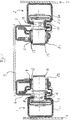
- Fig. 1:
- a longitudinal seat adjustment according to the invention in a partially sectioned front view; and
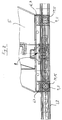
- Fig. 2
- the adjustment of FIG. 1 in side view.
Für die Langsverstellung der Sitze in einem Kraftfahrzeug ist dieses mit Führungsschienen - im dargestellten Ausführungsbeispiel gemäß Fig. 1 mit zwei Führungsschienen 1 und 2 - ausgestattet, die im Fußraum in Längsrichtung zur Fahrzeugachse zum einen an der Schwellerseite 3 und zum anderen an dem in der Mitte des Fahrzeugs verlaufenden Tunnel 4 angebracht sind. Ideal wäre für ein problemloses Funktionieren der Längsverstellung des Sitzes, wenn die Führungsschienen 1 und 2 genau parallel zueinander und in gleichen Ebenen verliefen. Dieser Idealzustand ist aufgrund der Maßabweichungen der Bauteile des Fahrzeugbodens und des Sitzes bei einer Serienfertigung nicht zu erreichen.For the longitudinal adjustment of the seats in a motor vehicle, this is equipped with guide rails - in the exemplary embodiment shown in FIG. 1 with two guide rails 1 and 2 - which in the footwell in the longitudinal direction to the vehicle axis on the one hand on the
Jede Führungsschiene 1 und 2 der erfindungsgemäßen Vorrichtung besteht aus mindestens zwei miteinander verschachtelten Metallprofilen 1.1 und 1.2 bzw. 2.1 und 2.2, wobei das jeweilige Außenprofil 1.1 bzw. 2.1 aus vergleichsweise dickwandigem Material der Aufnahme der hohen Belastungen dient, die auf den Sitz 5 und damit seine Führung einwirken, und das jeweilige Innenprofil 1.2 bzw. 2.2 aus vergleichsweise dünnwandigem Material, das von dem jeweils zugeordneten Außenprofil 1.1 bzw. 2.1 umfaßt ist, für die eigentliche Führung des Sitzes vorgesehen ist. Das dünnwandige Führungsprofil 1.2 bzw. 2.2 ist mit dem jeweils zugeordneten dickwandigen Halteprofil 1.1 bzw. 1.2 fest verbunden; beide so ineinandergefügten Profile sind jeweils über ihre Außenprofile 1.1 und 2.1 an den erwähnten Stellen der Fahrzeugkarosserie fixiert.Each
An der im Ausführungsbeispiel andeutungsweise gezeigten Basis des Fahrzeugsitzes 5 sind in Längsrichtung beidseitig in einem Abstand verlaufende Träger 6 und 7 mit dem Boden des Sitzes 5 unterseitig fest verbunden angebracht. Diese Träger 6 und 7 bieten zum einen einer in Fig. 2 schematisch dargestellten Verriegelungsvorrichtung 8 festen Halt und weisen zum anderen an ihren Endabschnitten quer zur Verschieberichtung des Sitzes angebrachte Lageraugen 9 bzw. 11 auf. Mittels geeigneter reibungsmindernder Lagermittel, vorzugsweise, wie im Ausführungsbeispiel angedeutet, mittels Wälzlagern 12 bzw. 13, ist in den Lageraugen jeweils ein zylinderförmiger Rollkörper 14 bzw. 15 drehbar gelagert. Einstückig mit jedem zylinderförmigen Rollkörper 14, 15 und auf derselben Rotationsachse ist ein annähernd einem Doppelkegelstumpf gleichender, profilierter Rollkörper verbunden, wobei dessen Kegelstumpfflächen 16 bzw. 17 mit ihrem kleineren Durchmesser einander gegenüberliegen und ihrerseits durch einen zylinderförmigen Teil 18 bzw. 19 verbunden sind, so daß sich aus dieser Formgebung gewissermaßen eine Spurrolle ergibt. Wie Fig. 2 zeigt, sind auf jeder Sitzlängsseite zwei derartige Spurrollen angeordnet, und zwar jeweils eine im vorderen und eine im hinteren Bereich. Diese aus dem zylinderförmigen Rollkörper 18 bzw. 19 und den profilierten, annähernd doppelkegelstumpfförmigen Rollkörpern 16 bzw. 17 einstückig ausgeführten Spurrollen sind an der einen Sitzseite - hier auf der Schwellerseite 3 - in Festlagern 21 und auf der anderen Sitzseite - Tunnelseite 4 - in Loslagern 22 um ihre Rotationsachse drehbar gelagert. Dem Fachmann sind die Begriffe Fest- und Loslager bekannt und bedürfen daher nicht der besonderen Erläuterung.On the base of the
Beim Einbau des Sitzes in das Fahrzeug werden die Spurrollen mit ihren nach außen weisenden Spurrändern in die schweller- und tunnelseitig angebrachten Führungsschienen eingeführt, womit der Fahrzeugsitz in seiner Längsrichtung gelagert ist und verschoben werden kann.When installing the seat in the vehicle, the track rollers with their outward-facing track edges are inserted into the sill and tunnel-side guide rails, whereby the vehicle seat is mounted in its longitudinal direction and can be moved.
Durch die auf der einen Sitzseite angebrachte feste Lagerung 21 der Rollvorrichtung ist eine Querbewegung des Sitzes 5 gegenüber der fahrzeugseitig angebrachten Führungsschiene 2, in der die Rollvorrichtung geführt wird, nicht bzw. nur in einem sehr geringen Maße, nämlich nur soweit möglich, wie es der Führungsspalt der Führungsschiene 2 dem doppelstumpfförmig profilierten Rollkörper 17, 19 erlaubt, eine Querbewegung zu vollführen.Due to the
Die auf der anderen Sitzseite axial verschieblich lose gestaltete Lagerung 22 der Spurrollen 16, 18 erlaubt es, Differenzen im Abstand der Führungsschienen zueinander in hohem Maße leicht auszugleichen, ohne daß sich der Führungsmechanismus in irgendeiner Weise verklemmt. Ebenso wie Abstandsfehler der Führungsschienen 1, 2 zueinander keinen Einfluß auf die leichtgängige Funktion der Verstellung haben, lassen sich auch Fehler in der Neigung der Führungsschienen zueinander ausgleichen. Durch die ballige Ausgestaltung der Laufflächen 1.2 und 2.2 der Führungsschienen 1 bzw. 2 und der nach innen gewölbten Lauffläche der Spurrollen 16 bzw. 17 (s.Fig. 1) ist zwischen beiden Flächen lediglich eine Punktberührung vorhanden, wodurch auch beim Verspannen der Rollvorrichtung durch Schieflage der Führungsschienen 1, 2 zueinander immer ein leichtes Verschieben des Sitzes 5 möglich ist, weil der Rollwiderstand auf ein sehr geringes Maß beschränkt bleibt.The axially displaceably loosely designed bearing 22 of the
Durch geeignete, hier nicht dargestellte Verkapselungen der sich drehenden Teile ist eine Gewähr für eine langlebige, verschleißfreie Funktion der Rolleinrichtung gegeben. Durch die drehbar gelagerten Spurrollen kann auf eine Schmierung der Führungsschienen verzichtet werden, wodurch sich das Problem von Funktionsstörungen, die aus der Verschmutzung resultieren, nicht mehr stellt. Staub- und Schmutzteile können sich zwar auf den gewölbten Führungsschienen ablagern, werden aber entweder bei ausreichender Korngröße beim Verstellen des Sitzes von der gewölbten Oberfläche fallen oder durch die hohe punktförmige Auflagelast der Spurrollen auf der gewölbten Oberfläche zermahlen und kommen somit für eine Beeinträchtigung der Funktion nicht in Betracht.Suitable encapsulation of the rotating parts, not shown here, guarantees a long-lasting, wear-free function of the roller device. Due to the rotatably mounted track rollers, there is no need to lubricate the guide rails, which means that the problem of malfunctions that result from soiling no longer arises. Dust and dirt particles can deposit on the curved guide rails, but will either fall off the curved surface when the seat is adjusted if the grain size is sufficient, or will be ground by the high point load of the track rollers on the curved surface and will therefore not impair the function into consideration.
Durch die aus den geringen Rollwiderständen zwischen Führungsschiene und Spurrollen resultierende Leichtgängigkeit ist eine gute Einhandbedienung der Längsverstellvorrichtung gegeben. Der Sitz kann mit Leichtigkeit nach seinem Entriegeln mit einer Hand in eine andere Position gebracht werden, was insbesondere von Vorteil ist, wenn der Raum hinter dem Sitz erreicht werden soll. Da bei dieser Vorrichtung ein Verkanten nicht vorkommt, eignet sich die Verstellvorrichtung insbesondere für die Verstellung von Sitzen, die eine Ausdehnung über die gesamte Breite des Innenraumes des Fahrzeugs aufweisen.The ease of movement resulting from the low rolling resistance between the guide rail and track rollers ensures good one-hand operation of the longitudinal adjustment device. The seat can be easily moved to a different position with one hand after it is unlocked, which is particularly advantageous if the space behind the seat is to be reached. Since tilting does not occur in this device, the adjustment device is particularly suitable for the adjustment of seats that have an expansion have over the entire width of the interior of the vehicle.
Nach dem Positionieren des Sitzes in seiner Längsposition wird dieser durch die Verriegelungsvorrichtung 8 in der gewählten Position fixiert. Beim Verriegeln werden die Spurrollen 16, 18 bzw. 17, 19 der Rollvorrichtung derart auf die zugehörige ballige Lauffläche 1.2 bzw. 2.2 der Führungsschienen gedrückt, daß das gesamte noch vorhandene Spiel zwischen Führungsschiene und Rollvorrichtung herausgedrückt ist und der Sitz klapperfrei in seiner Längsposition gehalten wird. Dies ist besonders bei nicht besetztem Sitz notwendig, da ansonsten durch die Fahrzeugschwingungen störende Geräusche durch Spiel in den Führungsschienen entstehen könnten.After positioning the seat in its longitudinal position, it is fixed in the selected position by the locking device 8. When locking, the
Claims (11)
Applications Claiming Priority (2)
| Application Number | Priority Date | Filing Date | Title |
|---|---|---|---|
| DE1995147034 DE19547034A1 (en) | 1995-12-15 | 1995-12-15 | Longitudinal seat adjustment |
| DE19547034 | 1995-12-15 |
Publications (2)
| Publication Number | Publication Date |
|---|---|
| EP0779174A2 true EP0779174A2 (en) | 1997-06-18 |
| EP0779174A3 EP0779174A3 (en) | 1998-09-02 |
Family
ID=7780318
Family Applications (1)
| Application Number | Title | Priority Date | Filing Date |
|---|---|---|---|
| EP96120174A Withdrawn EP0779174A3 (en) | 1995-12-15 | 1996-12-16 | Longitudinal adjustment of a seat |
Country Status (2)
| Country | Link |
|---|---|
| EP (1) | EP0779174A3 (en) |
| DE (1) | DE19547034A1 (en) |
Cited By (2)
| Publication number | Priority date | Publication date | Assignee | Title |
|---|---|---|---|---|
| WO2005053995A2 (en) * | 2003-11-28 | 2005-06-16 | Brose Fahrzeugteile Gmbh & Co. Kg, Coburg | Device for guiding two relatively movable subassemblies of a motor vehicle, particularly a motor vehicle seat, in one direction |
| WO2005051701A3 (en) * | 2003-11-28 | 2006-02-16 | Brose Fahrzeugteile | Device for guiding two sub-assemblies of a motor vehicle that are displaceable in relation to one another, in particular of a motor vehicle seat, in a guide direction |
Families Citing this family (7)
| Publication number | Priority date | Publication date | Assignee | Title |
|---|---|---|---|---|
| DE19738383A1 (en) | 1997-09-03 | 1999-03-04 | Johnson Controls Gmbh | Seat guide for longitudinally adjustable mounting of a vehicle seat |
| DE10340897A1 (en) * | 2003-09-01 | 2005-03-24 | Brose Fahrzeugteile Gmbh & Co. Kommanditgesellschaft, Coburg | Vehicle seat adjuster guide rail assembly includes transverse slack between rails of first guide rail pair, but none between rails of second pair |
| DE102015215631A1 (en) | 2015-08-17 | 2017-02-23 | Brose Fahrzeugteile Gmbh & Co. Kommanditgesellschaft, Bamberg | Device for manual and / or electromotive adjustment or locking of a first vehicle part and a second vehicle part relative to each other |
| DE102015215627A1 (en) | 2015-08-17 | 2017-02-23 | Brose Fahrzeugteile Gmbh & Co. Kommanditgesellschaft, Bamberg | Device for manual and / or electromotive adjustment or locking of a first vehicle part and a second vehicle part relative to each other |
| DE102015215630A1 (en) | 2015-08-17 | 2017-02-23 | Brose Fahrzeugteile Gmbh & Co. Kommanditgesellschaft, Bamberg | Device for manual and / or electromotive adjustment or locking of a first vehicle part and a second vehicle part relative to each other |
| DE102019216331A1 (en) * | 2019-10-23 | 2021-04-29 | Brose Fahrzeugteile SE & Co. Kommanditgesellschaft, Coburg | Seat depth adjustment device for a vehicle seat |
| DE102019216976A1 (en) * | 2019-10-23 | 2021-04-29 | Brose Fahrzeugteile SE & Co. Kommanditgesellschaft, Coburg | Seat depth adjustment device for a vehicle seat |
Citations (9)
| Publication number | Priority date | Publication date | Assignee | Title |
|---|---|---|---|---|
| GB318798A (en) * | 1928-11-20 | 1929-09-12 | Arthur Sam Cheston | Improvements relating to runner-fittings for sliding seats for vehicles |
| US3460794A (en) * | 1967-06-14 | 1969-08-12 | Gen Motors Corp | Seat adjuster |
| DE1680269A1 (en) * | 1967-10-04 | 1972-02-03 | Keiper Recaro Gmbh Co | Device for fastening a seat to a floor |
| DE3642441C1 (en) * | 1986-12-12 | 1988-09-01 | Audi Ag | Rail and roller guide |
| DE3920077A1 (en) * | 1988-06-30 | 1990-01-04 | Volkswagen Ag | Vehicle seat guided in rails |
| US5118062A (en) * | 1990-12-17 | 1992-06-02 | Bruno Archambault | Seat attachment assembly |
| US5348261A (en) * | 1992-12-21 | 1994-09-20 | General Motors Corporation | Low mass manual two-way seat adjuster |
| DE4330133A1 (en) * | 1993-09-06 | 1995-03-16 | Naue Johnson Controls Eng | Rail guide for vehicle seats |
| DE19519153A1 (en) * | 1994-05-30 | 1995-12-07 | Linde & Wiemann Gmbh Kg | Guide for adjustable seat of vehicle |
-
1995
- 1995-12-15 DE DE1995147034 patent/DE19547034A1/en not_active Withdrawn
-
1996
- 1996-12-16 EP EP96120174A patent/EP0779174A3/en not_active Withdrawn
Patent Citations (9)
| Publication number | Priority date | Publication date | Assignee | Title |
|---|---|---|---|---|
| GB318798A (en) * | 1928-11-20 | 1929-09-12 | Arthur Sam Cheston | Improvements relating to runner-fittings for sliding seats for vehicles |
| US3460794A (en) * | 1967-06-14 | 1969-08-12 | Gen Motors Corp | Seat adjuster |
| DE1680269A1 (en) * | 1967-10-04 | 1972-02-03 | Keiper Recaro Gmbh Co | Device for fastening a seat to a floor |
| DE3642441C1 (en) * | 1986-12-12 | 1988-09-01 | Audi Ag | Rail and roller guide |
| DE3920077A1 (en) * | 1988-06-30 | 1990-01-04 | Volkswagen Ag | Vehicle seat guided in rails |
| US5118062A (en) * | 1990-12-17 | 1992-06-02 | Bruno Archambault | Seat attachment assembly |
| US5348261A (en) * | 1992-12-21 | 1994-09-20 | General Motors Corporation | Low mass manual two-way seat adjuster |
| DE4330133A1 (en) * | 1993-09-06 | 1995-03-16 | Naue Johnson Controls Eng | Rail guide for vehicle seats |
| DE19519153A1 (en) * | 1994-05-30 | 1995-12-07 | Linde & Wiemann Gmbh Kg | Guide for adjustable seat of vehicle |
Cited By (4)
| Publication number | Priority date | Publication date | Assignee | Title |
|---|---|---|---|---|
| WO2005053995A2 (en) * | 2003-11-28 | 2005-06-16 | Brose Fahrzeugteile Gmbh & Co. Kg, Coburg | Device for guiding two relatively movable subassemblies of a motor vehicle, particularly a motor vehicle seat, in one direction |
| WO2005053995A3 (en) * | 2003-11-28 | 2006-02-16 | Brose Fahrzeugteile | Device for guiding two relatively movable subassemblies of a motor vehicle, particularly a motor vehicle seat, in one direction |
| WO2005051701A3 (en) * | 2003-11-28 | 2006-02-16 | Brose Fahrzeugteile | Device for guiding two sub-assemblies of a motor vehicle that are displaceable in relation to one another, in particular of a motor vehicle seat, in a guide direction |
| US7404537B2 (en) | 2003-11-28 | 2008-07-29 | Brose Fahrzeugteile Gmbh & Co Kg, Coburg | Device for guiding two sub-assemblies of a motor vehicle which are displaceable in relation to one another, in particular of a motor vehicle seat, in a guide direction |
Also Published As
| Publication number | Publication date |
|---|---|
| DE19547034A1 (en) | 1997-06-19 |
| EP0779174A3 (en) | 1998-09-02 |
Similar Documents
| Publication | Publication Date | Title |
|---|---|---|
| EP1066773B1 (en) | Slide | |
| DE69508742T2 (en) | DRAWER GUIDE | |
| EP1007385B1 (en) | Seat guide for fixing the adjustable longitudinal position of an automobile seat | |
| DE10229385B4 (en) | Device for fastening a restraint system of a means of transport or means of transport | |
| AT512934B1 (en) | drawer | |
| DE3643777C1 (en) | Door holder for motor vehicle doors | |
| DE102020203210A1 (en) | Steering column for a motor vehicle | |
| EP2183494A1 (en) | Linear guidance system comprising a hollow-profile rail | |
| EP0779174A2 (en) | Longitudinal adjustment of a seat | |
| DE69518785T2 (en) | Guide roller unit | |
| DE19519153C2 (en) | Guide for adjustable vehicle seats | |
| EP3624641B1 (en) | Guide device | |
| DE10202914B4 (en) | Retractable loading floor for a vehicle | |
| EP0568900B1 (en) | Space saving sliding rail system with two U-shaped slides, in particular for motor vehicle seats | |
| DE10104077A1 (en) | Adjusting system for arm rest mounted on car door comprises movable sleeves mounted on posts attached to bodywork, ratio between vertical distance between sleeves and horizontal distance between posts being made as large as possible | |
| WO2018234136A1 (en) | Arrangement of guide rails | |
| EP0517951B1 (en) | Device for fixing a housing supporting a rolling element for a linear bearing | |
| DE9315132U1 (en) | Swivel | |
| DE3420221A1 (en) | ADJUSTMENT DEVICE FOR VEHICLE SEATS | |
| DE19737034B4 (en) | Steering module of a motor vehicle with both in their inclination and in length adjustable steering column | |
| DE68923174T2 (en) | ARRANGEMENT FOR VEHICLE SEATS. | |
| DE10034008B4 (en) | Device for adjusting and locking a longitudinally displaceable seat | |
| DE9400343U1 (en) | Floor conveyor system | |
| DE102020105407B4 (en) | Transmission housing unit with a clamped thrust washer and transmission unit containing this transmission housing unit | |
| AT519530B1 (en) | DEVICE FOR MOVING A SHIFTER OF A SOFT |
Legal Events
| Date | Code | Title | Description |
|---|---|---|---|
| PUAI | Public reference made under article 153(3) epc to a published international application that has entered the european phase |
Free format text: ORIGINAL CODE: 0009012 |
|
| AK | Designated contracting states |
Kind code of ref document: A2 Designated state(s): DE FR GB |
|
| PUAL | Search report despatched |
Free format text: ORIGINAL CODE: 0009013 |
|
| AK | Designated contracting states |
Kind code of ref document: A3 Designated state(s): DE FR GB |
|
| STAA | Information on the status of an ep patent application or granted ep patent |
Free format text: STATUS: THE APPLICATION HAS BEEN WITHDRAWN |
|
| 18W | Application withdrawn |
Withdrawal date: 19981103 |