EP2705929B1 - Justagesystem für ein Transfersystem in einem in vitro-Diagnostiksystem - Google Patents
Justagesystem für ein Transfersystem in einem in vitro-Diagnostiksystem Download PDFInfo
- Publication number
- EP2705929B1 EP2705929B1 EP12183261.2A EP12183261A EP2705929B1 EP 2705929 B1 EP2705929 B1 EP 2705929B1 EP 12183261 A EP12183261 A EP 12183261A EP 2705929 B1 EP2705929 B1 EP 2705929B1
- Authority
- EP
- European Patent Office
- Prior art keywords
- adjustment
- contact element
- transfer
- vitro diagnostic
- joint
- Prior art date
- Legal status (The legal status is an assumption and is not a legal conclusion. Google has not performed a legal analysis and makes no representation as to the accuracy of the status listed.)
- Active
Links
Images

Classifications
-
- G—PHYSICS
- G01—MEASURING; TESTING
- G01B—MEASURING LENGTH, THICKNESS OR SIMILAR LINEAR DIMENSIONS; MEASURING ANGLES; MEASURING AREAS; MEASURING IRREGULARITIES OF SURFACES OR CONTOURS
- G01B21/00—Measuring arrangements or details thereof, where the measuring technique is not covered by the other groups of this subclass, unspecified or not relevant
- G01B21/16—Measuring arrangements or details thereof, where the measuring technique is not covered by the other groups of this subclass, unspecified or not relevant for measuring distance of clearance between spaced objects
-
- G—PHYSICS
- G01—MEASURING; TESTING
- G01N—INVESTIGATING OR ANALYSING MATERIALS BY DETERMINING THEIR CHEMICAL OR PHYSICAL PROPERTIES
- G01N35/00—Automatic analysis not limited to methods or materials provided for in any single one of groups G01N1/00 - G01N33/00; Handling materials therefor
- G01N35/10—Devices for transferring samples or any liquids to, in, or from, the analysis apparatus, e.g. suction devices, injection devices
- G01N35/1081—Devices for transferring samples or any liquids to, in, or from, the analysis apparatus, e.g. suction devices, injection devices characterised by the means for relatively moving the transfer device and the containers in an horizontal plane
- G01N35/109—Devices for transferring samples or any liquids to, in, or from, the analysis apparatus, e.g. suction devices, injection devices characterised by the means for relatively moving the transfer device and the containers in an horizontal plane with two horizontal degrees of freedom
-
- G—PHYSICS
- G01—MEASURING; TESTING
- G01N—INVESTIGATING OR ANALYSING MATERIALS BY DETERMINING THEIR CHEMICAL OR PHYSICAL PROPERTIES
- G01N35/00—Automatic analysis not limited to methods or materials provided for in any single one of groups G01N1/00 - G01N33/00; Handling materials therefor
- G01N35/10—Devices for transferring samples or any liquids to, in, or from, the analysis apparatus, e.g. suction devices, injection devices
Definitions
- the invention relates to an adjustment system for a transfer system in an in vitro diagnostic system, the adjustment system comprising a contact element which is arranged on a movable element of the transfer system.
- suitable vessels also known as cuvettes
- samples are used for samples, reagents and also for the actual detection reaction.
- cuvettes are used for samples, reagents and also for the actual detection reaction.
- These usually include a closed wall and an opening, which can be closed if necessary, for receiving the liquid to be analyzed.
- Today's devices are able to carry out a large number of detection reactions and analyzes with a sample.
- such in vitro diagnostic systems usually comprise a receiving position for a reaction vessel and an analysis system assigned to the receiving position.
- the sample vessel is usually transported several times to different addition and / or reaction stations.
- automatic analyzers have transfer systems, ie devices for the spatial transfer of the vessels, such as transfer arms, conveyor belts, rotating transport wheels or plates.
- the device includes a control unit which, by means of appropriate software, is able to plan and process the work steps for the desired analyzes largely independently.
- the object of the present invention is to provide an adjustment system which allows faster automated adjustment of transfer systems in an in vitro diagnostic system.
- the contact element is arranged on the movable element by means of a joint element, the joint element being designed to be self-resetting, and a distance measuring sensor being assigned to a distance between the contact element and the movable element.
- the invention has the advantage that a faster automated adjustment of transfer systems in an in vitro diagnostic system is possible if the adjustment without rigid and comparatively sensitive components such as in particular the needles previously used for capacitive Measurement.
- the contact element is mounted on a movable element of the transfer system and is designed to be self-resetting, i.e. the joint develops restoring forces when deflected from a defined rest position, e.g. by springs or other elastic components, contact can be determined by the deflection of the contact element and the joint .
- a distance measuring sensor is assigned to a distance between the contact element and the movable element.
- the distance measuring sensor does not have to be able to determine a continuously correct absolute value for the distance, but a simple determination of a relative change in the distance is sufficient.
- contact with a defined adjustment mark can be recognized in the in vitro diagnostic system and a position adjustment can be carried out.
- the distance measuring sensor advantageously comprises a Hall sensor and a magnet.
- the magnet is attached to one of the components and the Hall sensor to the other component.
- a change in the relative position of the magnet to the Hall sensor causes a change in the magnetic field generated in the Hall sensor and thus enables contact detection of the contact element at an adjustment mark.
- Due to the self-resetting properties of the joint element the magnet is always at the same distance from the Hall sensor without touching the contact element, so that the same magnetic field is always present here.
- Magnetic distance sensors have the advantage over capacitive sensors that they are particularly resistant to external influences from electromagnetic fields from e.g. mobile phones.
- the Hall sensor is advantageously arranged on the movable element and the magnet on the contact element. Basically, the structure for distance measurement can be symmetrically exchanged. However, the magnet is only a passive element, while the Hall sensor is the active, signal-producing element. Since the signals anyway are passed via the movable element and its drive into the control unit, such an attachment shortens the signal paths and simplifies the construction.
- the joint element is designed for a multidimensional movement. This results in a considerable simplification of the adjustment, since the adjustment can be carried out with the same contact element in any spatial direction. It is true that the direction of movement of the joint changes when the contact element comes into contact with an adjustment marker, depending on the direction of approach. In any case, however, a change in distance is associated with the contact, to which the distance measuring sensor reacts.
- the joint element comprises a rubber compound which connects the contact element and the movable element.
- a transfer system typically has a functional device which is typically arranged at the end of the transfer arm and is designed differently depending on the specific use of the transfer arm.
- This functional device is advantageously arranged on the contact element. On the one hand, this increases the accuracy of the adjustment, since the functional device is precisely the component of the transfer system which interacts with other components of the in vitro diagnostic system and therefore has to be precisely adjusted.
- the self-resetting joint element acts as a suspension for the functional device, which can be desired in interaction with other components of the in vitro diagnostic system.
- the functional device advantageously comprises a gripping device for gripping sample or reagent vessels and / or a pipetting device for transporting liquids.
- the functional device is arranged in relation to the joint element on a side facing away from the distance measuring sensor.
- the contact element thus acts practically as a lever over the joint element.
- a transfer system for an in vitro diagnostic system advantageously comprises a described adjustment system.
- An automated in vitro diagnostic system also advantageously comprises such a transfer system and / or a described adjustment system.
- the advantages achieved with the invention are, in particular, that by using a contact element attached via a hinge with a distance measuring sensor, small mechanical movements can be detected in all three dimensions and thus a faster and more precise adjustment is possible. In particular, manual adjustment is no longer necessary.
- the device can automatically record the current status and use the determined factors immediately and without the need for user support. There are no restrictions on the direction of movement, as adjustment in all three spatial directions is possible.
- Figure 1 shows a schematic representation of a transfer system 1 in the form of a transfer arm in an in vitro diagnostic system (not shown).
- the transfer system 1 comprises a movable element 2, which can be moved freely by a drive not shown in detail.
- the control of the movable element is controlled by a control unit, also not shown in detail.
- Corresponding sensors are located on the drive, which provide the control unit with information about the current position of the drive.
- an adjustment system 3 which comprises a contact element 4 which is attached to the movable element 2 of the transfer system 1 by means of a joint element 5.
- the joint element 5 consists of two rubber blocks which each connect the contact element 4 and the movable element 2 at a distance. The joint element 5 thus enables a multidimensional movement of the contact element 4 and the movable element 2 relative to one another, but automatically returns to the rest position.
- a functional device 6 designed as a cuvette gripper is arranged on the contact element 4. This is used to grip sample or reagent vessels. These are then transported within the in vitro diagnostic system by means of the transfer system 1.
- a magnet 7 is arranged on that of the Functional device 6 remote end of the contact element 4.
- a Hall sensor 8 on a printed circuit board 9 is assigned to the magnet 7 in the opposite area on the movable element 2. The Hall sensor 8 detects changes in the relative position of the magnet 7 in each direction due to the change in the magnetic field and forwards this information via the circuit board 9 to the control unit. Magnet 7 and Hall sensor 8 thus form a distance measuring sensor.
- the adjustment is carried out by moving the contact element 4 to an adjustment mark 10.
- the transfer system is moved in direction A.
- the contact element 4 with the functional device 6 strikes the adjustment mark 10.
- the contact element 4 executes an evasive movement B. This is possible due to the elasticity of the joint element 5.
- the magnet 7 in the contact element 4 and the Hall sensor 8 are at a certain distance.
- the evasive movement of the contact element 4 results in a change in this distance, represented by the movement C. This changes the magnetic field strength measured by the Hall sensor 8.
- the position of the adjustment mark 10 is thus recognized and is evaluated by the control unit for adjustment.
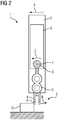
- Figure 2 shows the transfer system 1 Figure 1 from the direction R, shown in Figure 1 in a semi-transparent representation. All components from Figure 1 are also shown here, however shows Figure 2 that an adjustment in other spatial directions is also possible.
- the direction of the movement to the adjustment mark 10 is again shown as movement A, with movement A now perpendicular to movement A in FIG Figure 1 stands. Adjustment is also possible in this direction without changing adjustment system 3, represented by movements B and C.
Landscapes
- Physics & Mathematics (AREA)
- General Physics & Mathematics (AREA)
- Health & Medical Sciences (AREA)
- Life Sciences & Earth Sciences (AREA)
- Chemical & Material Sciences (AREA)
- Analytical Chemistry (AREA)
- Biochemistry (AREA)
- General Health & Medical Sciences (AREA)
- Immunology (AREA)
- Pathology (AREA)
- Automatic Analysis And Handling Materials Therefor (AREA)
Description
- Die Erfindung betrifft ein Justagesystem für ein Transfersystem in einem in vitro-Diagnostiksystem, wobei das Justagesystem ein Kontaktelement umfasst, welches an einem bewegbaren Element des Transfersystems angeordnet ist.
- Zahlreiche Nachweis- und Analyseverfahren zur Bestimmung physiologischer Parameter in Körperflüssigkeitsproben oder biologischen Proben werden heute automatisiert in großer Anzahl in entsprechenden in vitro-Diagnostiksystemen durchgeführt. Hierfür werden für Proben, Reagenzien und auch für die eigentliche Nachweisreaktion geeignete, auch als Küvetten bezeichnete, Gefäße verwendet. Diese umfassen üblicherweise eine geschlossene Umwandung sowie eine gegebenenfalls verschließbare Öffnung zur Aufnahme der jeweils zu analysierenden Flüssigkeit.
- Heutige Geräte sind in der Lage, eine Vielzahl von Nachweisreaktionen und Analysen mit einer Probe durchzuführen. Hierzu umfassen derartige in vitro-Diagnostiksysteme üblicherweise eine Aufnahmeposition für ein Reaktionsgefäß sowie ein der Aufnahmeposition zugeordnetes Analysesystem. Für komplexe, mehrere Prozessschritte umfassende Testverfahren wird das Probengefäß in der Regel mehrfach zu verschiedenen Zugabe- und/oder Reaktionsstationen transportiert. Um eine Vielzahl von Untersuchungen automatisiert durchführen zu können, verfügen automatische Analyzer über Transfersysteme, d.h. Vorrichtungen zum räumlichen Transfer der Gefäße, wie z.B. Transferarme, Transportbänder, drehbare Transporträder oder -teller. Das Gerät umfasst dabei eine Steuereinheit, die mittels entsprechender Software in der Lage ist, die Arbeitsschritte für die gewünschten Analysen weitgehend selbstständig zu planen und abzuarbeiten.
- Bei der Montage eines in vitro-Diagnostiksystems bleibt stets eine gewisse Ungenauigkeit hinsichtlich der Positionierung insbesondere der Transfersysteme bestehen. Da diese jedoch für den automatisierten Ablauf und das genaue Zusammenwirken exakte Positionierungsdaten benötigen, ist eine exakte Justage notwendig. Diese kann entweder manuell mit Hilfe von Justagemarken oder automatisch erfolgen.
- Für die automatische Justage ist üblicherweise zunächst ein entsprechender Sensor am Antrieb des jeweils zu justierenden beweglichen Elements des Transfersystems, z.B. an einem Teil eines Transferarms vorhanden, der an die Steuereinheit Informationen über die aktuelle Position des Antriebs weitergibt. Der Transferarm wird dann von der Steuereinheit kontrolliert auf eine Justagemarke zubewegt. Bislang bekannte Justagesysteme funktionieren häufig auf kapazitiver Basis, wobei als Kontaktelement eine Nadel an dem beweglichen Element auf eine kleine Metalloberfläche an der Justagemarke geführt wird. Wird eine Berührung erkannt, speichert die Steuereinheit die zugehörige Position des Antriebs ab.
US 2003/054543 A1 beschreibt ein Analysegerät bei dem die Position eines verfahrbareren Arms mittels einer Kamera und Hilfsmarkierungen genau bestimmt werden kann. - Aufgabe der vorliegenden Erfindung ist es, ein Justagesystem bereit zu stellen, welches eine schnellere automatisierte Justage von Transfersystemen in einem in vitro-Diagnostiksystem erlaubt.
- Diese Aufgabe wird erfindungsgemäß gelöst, indem das Kontaktelement mittels eines Gelenkelements an dem bewegbaren Element angeordnet ist, wobei das Gelenkelement selbstrückstellend ausgestaltet ist, und wobei einem Abstand zwischen Kontaktelement und bewegbarem Element ein Abstandsmesssensor zugeordnet ist.
- Die Erfindung hat den Vorteil, dass eine schnellere automatisierte Justage von Transfersystemen in einem in vitro-Diagnostiksystem möglich ist, wenn die Justage ohne starre und vergleichsweise empfindliche Bauteile wie insbesondere die bisher verwendeten Nadeln zur kapazitiven Messung auskommt. Wird das Kontaktelement an einem beweglichen Element des Transfersystems gelagert und ist selbstrückstellend ausgestaltet, d.h. das Gelenk entwickelt bei einer Auslenkung aus einer definierten Ruhelage Rückstellkräfte, z.B. durch Federn oder andere elastische Bauteile, so kann eine Berührung durch die Auslenkung des Kontaktelements und des Gelenks ermittelt werden. Dazu ist einem Abstand zwischen Kontaktelement und bewegbarem Element ein Abstandsmesssensor zugeordnet. Hierbei muss der Abstandsmesssensor keineswegs eine kontinuierlich korrekte absolute Größe für den Abstand ermitteln können, sondern eine einfache Feststellung einer relativen Änderung des Abstandes ist ausreichend. Durch eine Auslenkung aus der Ruhelage kann nämlich bereits eine Berührung einer definierten Justagemarke im in vitro-Diagnostiksystem erkannt werden und so eine Positionsjustierung durchgeführt werden.
- Vorteilhafterweise umfasst der Abstandsmesssensor einen Hall-Sensor und einen Magneten. Dabei ist jeweils an einem der Bauteile der Magnet und an dem anderen Bauteil der Hall-Sensor angebracht. Eine Veränderung der relativen Position des Magneten zum Hall-Sensor bedingt eine Veränderung des erzeugten Magnetfeldes im Hall-Sensor und ermöglicht so eine Kontakterkennung des Kontaktelements an einer Justagemarke. Durch die selbstrückstellenden Eigenschaften des Gelenkelements ist der Magnet ohne Berührung des Kontaktelements stets im selben Abstand zum Hall-Sensor, so dass hier stets dasselbe Magnetfeld anliegt. Eine magnetische Abstandssensorik hat gerade gegenüber der kapazitiven den Vorteil, dass sie besonders resistent gegen äußere Einflüsse durch elektromagnetische Felder von z.B. Mobiltelefonen ist.
- Vorteilhafterweise ist der Hall-Sensor dabei an dem bewegbaren Element und der Magnet an dem Kontaktelement angeordnet. Grundsätzlich ist der Aufbau zur Abstandsmessung symmetrisch austauschbar. Allerdings ist der Magnet lediglich ein passives Element, während der Hall-Sensor das aktive, signalproduzierende Element darstellt. Da die Signale ohnehin über das bewegliche Element und dessen Antrieb in die Steuereinheit geleitet werden, verkürzt eine derartige Anbringung die Signalwege und vereinfacht die Konstruktion.
- In vorteilhafter Ausgestaltung ist das Gelenkelement für eine mehrdimensionale Bewegung ausgebildet. Dadurch ergibt sich eine erhebliche Vereinfachung der Justage, da die Justage mit demselben Kontaktelement in jeder Raumrichtung durchgeführt werden kann. Zwar ändert sich die Bewegungsrichtung des Gelenks bei einem Kontakt des Kontaktelements mit einem Justagemarker je nach der Richtung der Annäherung. Mit dem Kontakt ist aber in jedem Fall eine Abstandsänderung verbunden, auf die der Abstandsmesssensor reagiert.
- In besonders vorteilhafter Ausgestaltung umfasst das Gelenkelement eine Gummimasse, die das Kontaktelement und das bewegbare Element verbindet. Hierdurch ergibt sich eine besonders einfache Ausgestaltung des Gelenkelements, da Gummi vorteilhafte Eigenschaften verbindet: Das Gelenk ist lange haltbar und wenig wartungsanfällig, der Gummi ermöglicht eine Bewegung in jede Dimension und bewegt sich selbstständig auf Grund seiner Elastizität in die Ruheposition zurück.
- Ein Transfersystem, insbesondere ein Transferarm weist typischerweise eine Funktionseinrichtung auf, die typischerweise am Ende des Transferarms angeordnet ist und je nach konkretem Einsatz des Transferarms unterschiedlich ausgestaltet ist. Diese Funktionseinrichtung ist vorteilhafterweise an dem Kontaktelement angeordnet. Dies erhöht einerseits die Genauigkeit der Justage, da die Funktionseinrichtung gerade das Bauteil des Transfersystems ist, welches mit anderen Bauteilen des in vitro-Diagnostiksystems zusammenwirkt und daher genau ausjustiert sein muss. Andererseits wirkt das selbstrückstellende Gelenkelement dabei als Federung für die Funktionseinrichtung, was im Zusammenspiel mit anderen Bauteilen des in vitro-Diagnostiksystems gewünscht sein kann. Vorteilhafterweise umfasst die Funktionseinrichtung eine Greifeinrichtung zum Greifen von Proben- oder Reagenzgefäßen und/oder eine Pipettiereinrichtung zum Transport von Flüssigkeiten.
- In weiterer vorteilhafter Ausgestaltung ist die Funktionseinrichtung dabei in Bezug auf das Gelenkelement an einer dem Abstandsmesssensor abgewandten Seite angeordnet. Damit wirkt das Kontaktelement praktisch als Hebel über dem Gelenkelement. Dadurch kann der Abstand des Abstandsmesssensors vom Gelenkelement vergrößert werden, womit sich auch die Auslenkung am Abstandsmesssensor erhöht. Dies verbessert die Genauigkeit der Messung.
- Ein Transfersystem für ein in vitro-Diagnostiksystem umfasst vorteilhafterweise ein beschriebenes Justagesystem. Ein automatisiertes in vitro-Diagnostiksystem umfasst ebenfalls vorteilhafterweise ein derartiges Transfersystem und/oder ein beschriebenes Justagesystem.
- Die mit der Erfindung erzielten Vorteile bestehen insbesondere darin, dass durch die Verwendung eines über ein Gelenk angebrachten Kontaktelements mit einem Abstandsmesssensor kleine mechanische Bewegungen in alle drei Dimensionen erfasst werden können und damit eine schnellere und exaktere Justage möglich wird. Insbesondere ist keine manuelle Justage mehr notwendig. Das Gerät kann den aktuellen Zustand automatisch erfassen und die dabei ermittelten Faktoren sofort und ohne notwendige Unterstützung eines Benutzers verwenden. Hierbei gibt es keine Einschränkung der Bewegungsrichtung, da eine Justage in alle drei Raumrichtungen möglich ist.
- Die Erfindung wird anhand einer Zeichnung näher erläutert. Darin zeigen:
- Figur 1
- eine schematische Darstellung eines Transfersystems in Form eines Transferarms bei der automatischen Justage in einer ersten Raumrichtung, und
- Figur 2
- eine schematische Darstellung des Transfersystems bei der automatischen Justage in einer zweiten Raumrichtung.
- Gleiche Teile sind in allen Figuren mit denselben Bezugszeichen versehen.
-
Figur 1 zeigt eine schematische Darstellung eines Transfersystems 1 in Form eines Transferarms in einem nicht dargestellten in vitro-Diagnostiksystem. Das Transfersystem 1 umfasst ein bewegliches Element 2, welches durch einen nicht näher dargestellten Antrieb frei bewegt werden kann. Die Steuerung des beweglichen Elements wird von einer ebenfalls nicht näher dargestellten Steuereinheit gesteuert. Am Antrieb befinden sich entsprechende Sensoren, die der Steuereinheit Informationen über die aktuelle Stellung des Antriebs liefern. - Zur genauen Justage des Transfersystems 1 ist ein Justagesystem 3 vorgesehen, welches ein Kontaktelement 4 umfasst, das mittels eines Gelenkelements 5 an dem beweglichen Element 2 des Transfersystems 1 angebracht ist. Das Gelenkelement 5 besteht aus zwei Gummiblöcken, die in einem Abstand jeweils das Kontaktelement 4 und das bewegliche Element 2 verbinden. Das Gelenkelement 5 ermöglicht so eine mehrdimensionale Bewegung von Kontaktelement 4 und beweglichem Element 2 gegeneinander, stellt sich jedoch selbstständig in die Ruheposition zurück.
- An dem Kontaktelement 4 ist eine als Küvettengreifer ausgelegte Funktionseinrichtung 6 angeordnet. Diese dient zum Ergreifen von Proben- oder Reagenzgefäßen. Mittels des Transfersystems 1 werden diese dann innerhalb des in vitro-Diagnostiksystems transportiert. An dem von der Funktionseinrichtung 6 entfernten Ende des Kontaktelements 4 ist ein Magnet 7 angeordnet. Dem Magnet 7 ist im gegenüber liegenden Bereich auf dem beweglichen Element 2 ein Hall-Sensor 8 auf einer Leiterplatte 9 zugeordnet. Der Hall-Sensor 8 detektiert Änderungen der Relativposition des Magneten 7 in jede Richtung durch die Änderung des magnetischen Feldes und leitet diese Information über die Leiterplatte 9 der Steuereinheit zu. Magnet 7 und Hall-Sensor 8 bilden somit einen Abstandsmesssensor.
- Die Justage wird durchgeführt, indem das Kontaktelement 4 an eine Justagemarke 10 geführt wird. In
Figur 1 wird das Transfersystem in Richtung A bewegt. An der zu bestimmenden Position stößt das Kontaktelement 4 mit der Funktionseinrichtung 6 an die Justagemarke 10. In diesem Moment führt das Kontaktelement 4 eine Ausweichbewegung B aus. Dies ist durch die Elastizität des Gelenkelements 5 möglich. In Ruheposition haben der Magnet 7 im Kontaktelement 4 und der Hall-Sensor 8 einen bestimmten Abstand. Die Ausweichbewegung des Kontaktelements 4 resultiert in einer Veränderung dieses Abstandes, dargestellt durch die Bewegung C. Dadurch ändert sich die vom Hall-Sensor 8 gemessene Magnetfeldstärke. Die Position der Justagemarke 10 ist somit erkannt und wird von der Steuereinheit zur Justage ausgewertet. -
Figur 2 zeigt das Transfersystem 1 ausFigur 1 aus der Richtung R, dargestellt inFigur 1 in einer halbtransparenten Darstellung. Sämtliche Bauteile ausFigur 1 sind auch hier dargestellt, allerdings zeigtFigur 2 , dass auch eine Justage in andere Raumrichtungen möglich ist. Die Richtung der Bewegung an die Justagemarke 10 ist wiederum als Bewegung A dargestellt, wobei die Bewegung A nunmehr senkrecht zur Bewegung A inFigur 1 steht. Auch in dieser Richtung ist eine Justage möglich, ohne das Justagesystem 3 zu verändern, dargestellt durch die Bewegungen B und C. -
- 1
- Transfersystem
- 2
- bewegliches Element
- 3
- Justagesystem
- 4
- Kontaktelement
- 5
- Gelenkelement
- 6
- Funktionseinrichtung
- 7
- Magnet
- 8
- Hall-Sensor
- 9
- Leiterplatte
- 10
- Justagemarke
Claims (7)
- Automatisiertes in vitro-Diagnostiksystem mit einem Transfersystem (1) und einem Justagesystem (3) für das Transfersystem (1), dadurch gekennzeichnet, dass das Justagesystem (3) ein Kontaktelement (4) umfasst, welches an einem bewegbaren Element (2) des Transfersystems (1) mittels eines Gelenkelements (5) angeordnet ist, wobei das Gelenkelement (5) selbstrückstellend ausgestaltet ist und für eine mehrdimensionale Bewegung ausgebildet ist, und wobei einem Abstand zwischen Kontaktelement (4) und bewegbarem Element (2) ein Abstandsmesssensor (7, 8) zugeordnet ist.
- In vitro-Diagnostiksystem nach Anspruch 1, bei dem der Abstandsmesssensor (7, 8) einen Hall-Sensor (8) und einen Magneten (7) umfasst.
- In vitro-Diagnostiksystem nach Anspruch 2, bei dem der Hall-Sensor (8) an dem bewegbaren Element (2) und der Magnet (7) an dem Kontaktelement (4) angeordnet ist.
- In vitro-Diagnostiksystem nach einem der vorhergehenden Ansprüche, bei dem das Gelenkelement (5) eine Gummimasse umfasst, die das Kontaktelement (4) und das bewegbare Element (2) verbindet.
- In vitro-Diagnostiksystem nach einem der vorhergehenden Ansprüche, bei dem an dem Kontaktelement (4) eine Funktionseinrichtung (6) angeordnet ist.
- In vitro-Diagnostiksystem nach Anspruch 5, bei dem die Funktionseinrichtung (6) eine Greifeinrichtung und/oder eine Pipettiereinrichtung umfasst.
- In vitro-Diagnostiksystem nach Anspruch 5 oder 6, bei dem die Funktionseinrichtung (6) in Bezug auf das Gelenkelement (5) an einer dem Abstandsmesssensor (7, 8) abgewandten Seite angeordnet ist.
Priority Applications (4)
| Application Number | Priority Date | Filing Date | Title |
|---|---|---|---|
| ES12183261T ES2875039T3 (es) | 2012-09-06 | 2012-09-06 | Sistema de ajuste para un sistema de transferencia en un sistema de diagnóstico in vitro |
| EP12183261.2A EP2705929B1 (de) | 2012-09-06 | 2012-09-06 | Justagesystem für ein Transfersystem in einem in vitro-Diagnostiksystem |
| US13/971,280 US9372080B2 (en) | 2012-09-06 | 2013-08-20 | Adjustment system for a transfer system in an in-vitro diagnostics system |
| JP2013185145A JP6304977B2 (ja) | 2012-09-06 | 2013-09-06 | インビトロ診断システム |
Applications Claiming Priority (1)
| Application Number | Priority Date | Filing Date | Title |
|---|---|---|---|
| EP12183261.2A EP2705929B1 (de) | 2012-09-06 | 2012-09-06 | Justagesystem für ein Transfersystem in einem in vitro-Diagnostiksystem |
Publications (2)
| Publication Number | Publication Date |
|---|---|
| EP2705929A1 EP2705929A1 (de) | 2014-03-12 |
| EP2705929B1 true EP2705929B1 (de) | 2021-04-14 |
Family
ID=47172262
Family Applications (1)
| Application Number | Title | Priority Date | Filing Date |
|---|---|---|---|
| EP12183261.2A Active EP2705929B1 (de) | 2012-09-06 | 2012-09-06 | Justagesystem für ein Transfersystem in einem in vitro-Diagnostiksystem |
Country Status (4)
| Country | Link |
|---|---|
| US (1) | US9372080B2 (de) |
| EP (1) | EP2705929B1 (de) |
| JP (1) | JP6304977B2 (de) |
| ES (1) | ES2875039T3 (de) |
Families Citing this family (7)
| Publication number | Priority date | Publication date | Assignee | Title |
|---|---|---|---|---|
| EP3096148B1 (de) | 2015-05-20 | 2024-01-03 | Siemens Healthcare Diagnostics Products GmbH | Pipettiervorrichtung |
| ES2898175T3 (es) * | 2016-01-22 | 2022-03-04 | Siemens Healthcare Diagnostics Products Gmbh | Sistema de ajuste. |
| WO2017142987A1 (en) * | 2016-02-19 | 2017-08-24 | Siemens Healthcare Diagnostics Inc. | Single-piece transfer arm structure for analytical instrumentation |
| ES2822926T3 (es) * | 2016-03-17 | 2021-05-05 | Siemens Healthcare Diagnostics Products Gmbh | Procedimiento para el monitoreo del transporte de recipientes de líquidos en un dispositivo de análisis automático |
| EP3454987B1 (de) * | 2016-05-12 | 2021-06-30 | Siemens Healthcare Diagnostics Inc. | Mechanismus und verfahren zur aufprallerkennung der sonde eines klinischen analysators |
| WO2018017770A1 (en) * | 2016-07-21 | 2018-01-25 | Siemens Healthcare Diagnostics Inc. | System and method for condition based monitoring and maintenance of an automation track |
| EP3293524B1 (de) * | 2016-09-12 | 2021-06-09 | Stratec SE | Fluidische kupplung |
Family Cites Families (19)
| Publication number | Priority date | Publication date | Assignee | Title |
|---|---|---|---|---|
| CH414798A (de) * | 1960-09-22 | 1966-06-15 | Siemens Ag | Kontaktloser Befehlsgeber |
| US3819888A (en) * | 1973-02-26 | 1974-06-25 | Cutler Hammer Inc | Limit switch mechanism |
| JPS61275660A (ja) * | 1985-05-31 | 1986-12-05 | Hitachi Ltd | サンプリング装置 |
| JP2524728B2 (ja) * | 1987-01-16 | 1996-08-14 | 和光純薬工業株式会社 | 透過光測定装置 |
| DE59308553D1 (de) * | 1992-02-13 | 1998-06-25 | Hoffmann La Roche | Automatische Pipettiervorrichtung |
| US5273717A (en) * | 1992-09-30 | 1993-12-28 | Eastman Kodak Company | Self-calibrating analyzer aspirator |
| US5512247A (en) * | 1994-05-02 | 1996-04-30 | Hoffmann-La Roche Inc. | Apparatus for testing pipetting needle linearity in an automated analyzer |
| US20030054543A1 (en) * | 1997-06-16 | 2003-03-20 | Lafferty William Michael | Device for moving a selected station of a holding plate to a predetermined location for interaction with a probe |
| JP3765255B2 (ja) * | 2001-08-21 | 2006-04-12 | 株式会社日立製作所 | 攪拌装置およびそれを用いた自動分析装置 |
| JP4156822B2 (ja) * | 2001-09-11 | 2008-09-24 | アロカ株式会社 | ハンドリング装置 |
| JP2003344427A (ja) * | 2002-05-22 | 2003-12-03 | Aloka Co Ltd | 分注装置 |
| JP4355682B2 (ja) * | 2005-06-16 | 2009-11-04 | アロカ株式会社 | 自動分注装置及び自動分注方法 |
| JP4646311B2 (ja) * | 2005-11-22 | 2011-03-09 | 株式会社スギノマシン | ノズル先端基準高さ位置調整装置及びサンプリング装置 |
| US7932684B2 (en) * | 2008-03-25 | 2011-04-26 | Bose Corporation | Absolute position sensing |
| JP5157950B2 (ja) * | 2009-02-05 | 2013-03-06 | 横河電機株式会社 | 分注装置 |
| JP5275182B2 (ja) * | 2009-09-11 | 2013-08-28 | 株式会社日立ハイテクノロジーズ | 分注装置及び分析装置 |
| DE102009048918A1 (de) * | 2009-10-10 | 2011-04-14 | Siemens Healthcare Diagnostics Products Gmbh | Vorrichtung zum Mischen einer Flüssigkeitsprobe |
| EP2752670A2 (de) * | 2010-07-23 | 2014-07-09 | Beckman Coulter, Inc. | System oder Verfahren zur Aufnahme analytischer Einheiten |
| JP5371905B2 (ja) * | 2010-07-30 | 2013-12-18 | シスメックス株式会社 | 検体処理装置の管理システム、検体処理装置及び管理装置ならびに管理方法 |
-
2012
- 2012-09-06 ES ES12183261T patent/ES2875039T3/es active Active
- 2012-09-06 EP EP12183261.2A patent/EP2705929B1/de active Active
-
2013
- 2013-08-20 US US13/971,280 patent/US9372080B2/en active Active
- 2013-09-06 JP JP2013185145A patent/JP6304977B2/ja active Active
Non-Patent Citations (1)
| Title |
|---|
| None * |
Also Published As
| Publication number | Publication date |
|---|---|
| US20140065017A1 (en) | 2014-03-06 |
| ES2875039T3 (es) | 2021-11-08 |
| US9372080B2 (en) | 2016-06-21 |
| EP2705929A1 (de) | 2014-03-12 |
| JP2014052376A (ja) | 2014-03-20 |
| JP6304977B2 (ja) | 2018-04-04 |
Similar Documents
| Publication | Publication Date | Title |
|---|---|---|
| EP2705929B1 (de) | Justagesystem für ein Transfersystem in einem in vitro-Diagnostiksystem | |
| EP3452833B1 (de) | Verfahren zur positionsbestimmung eines roboterarms in einem flüssigkeitshandhabungssystem sowie ein entsprechendes flüssigkeitshandhabungssystem | |
| EP2927695B1 (de) | Probenverteilungssystem und Laborautomatisierungssystem | |
| WO2018015545A1 (de) | Verfahren zur positionsbestimmung eines roboterarms in einem flüssigkeitshandhabungssystem sowie ein entsprechendes flüssigkeitshandhabungssystem | |
| DE102013214694B4 (de) | Verfahren zum Handhaben eines Gegenstands und Vorrichtung zum Handhaben von Gegenständen | |
| EP2841873B1 (de) | Sensorelement für eine messmaschine, insbesondere eine koordinatenmessmaschine | |
| EP3025780B1 (de) | Inkubationswanne | |
| EP3216517B1 (de) | Verfahren zum durchmischen einer flüssigkeit in einem automatischen analysegerät | |
| EP3096148B1 (de) | Pipettiervorrichtung | |
| CH709198A2 (de) | Transporteinrichtung für flüssige oder feste NMR-Proben. | |
| EP1627203B1 (de) | Verfahren zur kalibrierung eines tasters | |
| EP2793031B1 (de) | Pipettiersystem für ein Analysegerät | |
| DE102020105215A1 (de) | Verfahren zum Kalibrieren einer Sensoreinheit eines Flurförderzeugs | |
| EP2977767B1 (de) | Vorrichtung zur Positionsbestimmung einer automatisch verfahrbaren Lehre | |
| DE69000915T2 (de) | Sich hin- und herbewegende ueberfuehrungsvorrichtung. | |
| DE102010043026A1 (de) | Elektronisches Gerät und Verfahren zur Inbetriebnahme eines elektronischen Gerätes | |
| EP3196649B1 (de) | Justagesystem | |
| EP3173794B1 (de) | Verfahren zum transfer eines flüssigkeitsvolumens in einem analysegerät | |
| DE102020134318A1 (de) | Handhabung von Laborelementen | |
| EP3211423A1 (de) | Automatisches analysegerät mit aufnahmepositionen für flüssigkeitsbehälter | |
| EP4146442A1 (de) | Greifvorrichtung zum transfer eines magnetischen dipolstabs | |
| EP3220148B1 (de) | Verfahren zur überwachung des transports von flüssigkeitsbehältern in einem automatischen analysegerät | |
| WO1996027153A1 (de) | Verfahren zum kalibrieren des arbeitspunktes eines roboters | |
| DE102020105496B4 (de) | Verstellvorrichtung für ein Kraftfahrzeug | |
| DE212019000440U1 (de) | Automatisierbare Temperiervorrichtung |
Legal Events
| Date | Code | Title | Description |
|---|---|---|---|
| PUAI | Public reference made under article 153(3) epc to a published international application that has entered the european phase |
Free format text: ORIGINAL CODE: 0009012 |
|
| AK | Designated contracting states |
Kind code of ref document: A1 Designated state(s): AL AT BE BG CH CY CZ DE DK EE ES FI FR GB GR HR HU IE IS IT LI LT LU LV MC MK MT NL NO PL PT RO RS SE SI SK SM TR |
|
| AX | Request for extension of the european patent |
Extension state: BA ME |
|
| 17P | Request for examination filed |
Effective date: 20140805 |
|
| RBV | Designated contracting states (corrected) |
Designated state(s): AL AT BE BG CH CY CZ DE DK EE ES FI FR GB GR HR HU IE IS IT LI LT LU LV MC MK MT NL NO PL PT RO RS SE SI SK SM TR |
|
| STAA | Information on the status of an ep patent application or granted ep patent |
Free format text: STATUS: EXAMINATION IS IN PROGRESS |
|
| 17Q | First examination report despatched |
Effective date: 20190618 |
|
| GRAP | Despatch of communication of intention to grant a patent |
Free format text: ORIGINAL CODE: EPIDOSNIGR1 |
|
| STAA | Information on the status of an ep patent application or granted ep patent |
Free format text: STATUS: GRANT OF PATENT IS INTENDED |
|
| INTG | Intention to grant announced |
Effective date: 20210122 |
|
| RIN1 | Information on inventor provided before grant (corrected) |
Inventor name: HERZ, ACHIM Inventor name: WIEDEKIND-KLEIN, ALEXANDER |
|
| GRAS | Grant fee paid |
Free format text: ORIGINAL CODE: EPIDOSNIGR3 |
|
| GRAA | (expected) grant |
Free format text: ORIGINAL CODE: 0009210 |
|
| STAA | Information on the status of an ep patent application or granted ep patent |
Free format text: STATUS: THE PATENT HAS BEEN GRANTED |
|
| AK | Designated contracting states |
Kind code of ref document: B1 Designated state(s): AL AT BE BG CH CY CZ DE DK EE ES FI FR GB GR HR HU IE IS IT LI LT LU LV MC MK MT NL NO PL PT RO RS SE SI SK SM TR |
|
| REG | Reference to a national code |
Ref country code: GB Ref legal event code: FG4D Free format text: NOT ENGLISH |
|
| REG | Reference to a national code |
Ref country code: CH Ref legal event code: EP |
|
| REG | Reference to a national code |
Ref country code: CH Ref legal event code: NV Representative=s name: SIEMENS SCHWEIZ AG, CH |
|
| REG | Reference to a national code |
Ref country code: DE Ref legal event code: R096 Ref document number: 502012016721 Country of ref document: DE |
|
| REG | Reference to a national code |
Ref country code: IE Ref legal event code: FG4D Free format text: LANGUAGE OF EP DOCUMENT: GERMAN |
|
| REG | Reference to a national code |
Ref country code: AT Ref legal event code: REF Ref document number: 1381892 Country of ref document: AT Kind code of ref document: T Effective date: 20210515 |
|
| REG | Reference to a national code |
Ref country code: SE Ref legal event code: TRGR |
|
| REG | Reference to a national code |
Ref country code: LT Ref legal event code: MG9D |
|
| REG | Reference to a national code |
Ref country code: NL Ref legal event code: MP Effective date: 20210414 |
|
| PG25 | Lapsed in a contracting state [announced via postgrant information from national office to epo] |
Ref country code: LT Free format text: LAPSE BECAUSE OF FAILURE TO SUBMIT A TRANSLATION OF THE DESCRIPTION OR TO PAY THE FEE WITHIN THE PRESCRIBED TIME-LIMIT Effective date: 20210414 Ref country code: NL Free format text: LAPSE BECAUSE OF FAILURE TO SUBMIT A TRANSLATION OF THE DESCRIPTION OR TO PAY THE FEE WITHIN THE PRESCRIBED TIME-LIMIT Effective date: 20210414 Ref country code: FI Free format text: LAPSE BECAUSE OF FAILURE TO SUBMIT A TRANSLATION OF THE DESCRIPTION OR TO PAY THE FEE WITHIN THE PRESCRIBED TIME-LIMIT Effective date: 20210414 Ref country code: HR Free format text: LAPSE BECAUSE OF FAILURE TO SUBMIT A TRANSLATION OF THE DESCRIPTION OR TO PAY THE FEE WITHIN THE PRESCRIBED TIME-LIMIT Effective date: 20210414 Ref country code: BG Free format text: LAPSE BECAUSE OF FAILURE TO SUBMIT A TRANSLATION OF THE DESCRIPTION OR TO PAY THE FEE WITHIN THE PRESCRIBED TIME-LIMIT Effective date: 20210714 |
|
| REG | Reference to a national code |
Ref country code: ES Ref legal event code: FG2A Ref document number: 2875039 Country of ref document: ES Kind code of ref document: T3 Effective date: 20211108 |
|
| PG25 | Lapsed in a contracting state [announced via postgrant information from national office to epo] |
Ref country code: GR Free format text: LAPSE BECAUSE OF FAILURE TO SUBMIT A TRANSLATION OF THE DESCRIPTION OR TO PAY THE FEE WITHIN THE PRESCRIBED TIME-LIMIT Effective date: 20210715 Ref country code: LV Free format text: LAPSE BECAUSE OF FAILURE TO SUBMIT A TRANSLATION OF THE DESCRIPTION OR TO PAY THE FEE WITHIN THE PRESCRIBED TIME-LIMIT Effective date: 20210414 Ref country code: IS Free format text: LAPSE BECAUSE OF FAILURE TO SUBMIT A TRANSLATION OF THE DESCRIPTION OR TO PAY THE FEE WITHIN THE PRESCRIBED TIME-LIMIT Effective date: 20210814 Ref country code: RS Free format text: LAPSE BECAUSE OF FAILURE TO SUBMIT A TRANSLATION OF THE DESCRIPTION OR TO PAY THE FEE WITHIN THE PRESCRIBED TIME-LIMIT Effective date: 20210414 Ref country code: NO Free format text: LAPSE BECAUSE OF FAILURE TO SUBMIT A TRANSLATION OF THE DESCRIPTION OR TO PAY THE FEE WITHIN THE PRESCRIBED TIME-LIMIT Effective date: 20210714 Ref country code: PL Free format text: LAPSE BECAUSE OF FAILURE TO SUBMIT A TRANSLATION OF THE DESCRIPTION OR TO PAY THE FEE WITHIN THE PRESCRIBED TIME-LIMIT Effective date: 20210414 Ref country code: PT Free format text: LAPSE BECAUSE OF FAILURE TO SUBMIT A TRANSLATION OF THE DESCRIPTION OR TO PAY THE FEE WITHIN THE PRESCRIBED TIME-LIMIT Effective date: 20210816 |
|
| REG | Reference to a national code |
Ref country code: DE Ref legal event code: R097 Ref document number: 502012016721 Country of ref document: DE |
|
| PG25 | Lapsed in a contracting state [announced via postgrant information from national office to epo] |
Ref country code: CZ Free format text: LAPSE BECAUSE OF FAILURE TO SUBMIT A TRANSLATION OF THE DESCRIPTION OR TO PAY THE FEE WITHIN THE PRESCRIBED TIME-LIMIT Effective date: 20210414 Ref country code: DK Free format text: LAPSE BECAUSE OF FAILURE TO SUBMIT A TRANSLATION OF THE DESCRIPTION OR TO PAY THE FEE WITHIN THE PRESCRIBED TIME-LIMIT Effective date: 20210414 Ref country code: EE Free format text: LAPSE BECAUSE OF FAILURE TO SUBMIT A TRANSLATION OF THE DESCRIPTION OR TO PAY THE FEE WITHIN THE PRESCRIBED TIME-LIMIT Effective date: 20210414 Ref country code: SM Free format text: LAPSE BECAUSE OF FAILURE TO SUBMIT A TRANSLATION OF THE DESCRIPTION OR TO PAY THE FEE WITHIN THE PRESCRIBED TIME-LIMIT Effective date: 20210414 Ref country code: SK Free format text: LAPSE BECAUSE OF FAILURE TO SUBMIT A TRANSLATION OF THE DESCRIPTION OR TO PAY THE FEE WITHIN THE PRESCRIBED TIME-LIMIT Effective date: 20210414 Ref country code: RO Free format text: LAPSE BECAUSE OF FAILURE TO SUBMIT A TRANSLATION OF THE DESCRIPTION OR TO PAY THE FEE WITHIN THE PRESCRIBED TIME-LIMIT Effective date: 20210414 |
|
| PLBE | No opposition filed within time limit |
Free format text: ORIGINAL CODE: 0009261 |
|
| STAA | Information on the status of an ep patent application or granted ep patent |
Free format text: STATUS: NO OPPOSITION FILED WITHIN TIME LIMIT |
|
| 26N | No opposition filed |
Effective date: 20220117 |
|
| REG | Reference to a national code |
Ref country code: BE Ref legal event code: MM Effective date: 20210930 |
|
| PG25 | Lapsed in a contracting state [announced via postgrant information from national office to epo] |
Ref country code: IS Free format text: LAPSE BECAUSE OF FAILURE TO SUBMIT A TRANSLATION OF THE DESCRIPTION OR TO PAY THE FEE WITHIN THE PRESCRIBED TIME-LIMIT Effective date: 20210814 Ref country code: MC Free format text: LAPSE BECAUSE OF FAILURE TO SUBMIT A TRANSLATION OF THE DESCRIPTION OR TO PAY THE FEE WITHIN THE PRESCRIBED TIME-LIMIT Effective date: 20210414 Ref country code: AL Free format text: LAPSE BECAUSE OF FAILURE TO SUBMIT A TRANSLATION OF THE DESCRIPTION OR TO PAY THE FEE WITHIN THE PRESCRIBED TIME-LIMIT Effective date: 20210414 |
|
| PG25 | Lapsed in a contracting state [announced via postgrant information from national office to epo] |
Ref country code: LU Free format text: LAPSE BECAUSE OF NON-PAYMENT OF DUE FEES Effective date: 20210906 Ref country code: IE Free format text: LAPSE BECAUSE OF NON-PAYMENT OF DUE FEES Effective date: 20210906 Ref country code: BE Free format text: LAPSE BECAUSE OF NON-PAYMENT OF DUE FEES Effective date: 20210930 |
|
| REG | Reference to a national code |
Ref country code: AT Ref legal event code: MM01 Ref document number: 1381892 Country of ref document: AT Kind code of ref document: T Effective date: 20210906 |
|
| PG25 | Lapsed in a contracting state [announced via postgrant information from national office to epo] |
Ref country code: AT Free format text: LAPSE BECAUSE OF NON-PAYMENT OF DUE FEES Effective date: 20210906 |
|
| PGFP | Annual fee paid to national office [announced via postgrant information from national office to epo] |
Ref country code: ES Payment date: 20221216 Year of fee payment: 11 |
|
| PG25 | Lapsed in a contracting state [announced via postgrant information from national office to epo] |
Ref country code: HU Free format text: LAPSE BECAUSE OF FAILURE TO SUBMIT A TRANSLATION OF THE DESCRIPTION OR TO PAY THE FEE WITHIN THE PRESCRIBED TIME-LIMIT; INVALID AB INITIO Effective date: 20120906 Ref country code: CY Free format text: LAPSE BECAUSE OF FAILURE TO SUBMIT A TRANSLATION OF THE DESCRIPTION OR TO PAY THE FEE WITHIN THE PRESCRIBED TIME-LIMIT Effective date: 20210414 |
|
| PGFP | Annual fee paid to national office [announced via postgrant information from national office to epo] |
Ref country code: IT Payment date: 20230920 Year of fee payment: 12 |
|
| PGFP | Annual fee paid to national office [announced via postgrant information from national office to epo] |
Ref country code: SE Payment date: 20230911 Year of fee payment: 12 |
|
| PG25 | Lapsed in a contracting state [announced via postgrant information from national office to epo] |
Ref country code: MK Free format text: LAPSE BECAUSE OF FAILURE TO SUBMIT A TRANSLATION OF THE DESCRIPTION OR TO PAY THE FEE WITHIN THE PRESCRIBED TIME-LIMIT Effective date: 20210414 |
|
| PG25 | Lapsed in a contracting state [announced via postgrant information from national office to epo] |
Ref country code: TR Free format text: LAPSE BECAUSE OF FAILURE TO SUBMIT A TRANSLATION OF THE DESCRIPTION OR TO PAY THE FEE WITHIN THE PRESCRIBED TIME-LIMIT Effective date: 20210414 |
|
| PG25 | Lapsed in a contracting state [announced via postgrant information from national office to epo] |
Ref country code: MT Free format text: LAPSE BECAUSE OF FAILURE TO SUBMIT A TRANSLATION OF THE DESCRIPTION OR TO PAY THE FEE WITHIN THE PRESCRIBED TIME-LIMIT Effective date: 20210414 |
|
| REG | Reference to a national code |
Ref country code: ES Ref legal event code: FD2A Effective date: 20241025 |
|
| PG25 | Lapsed in a contracting state [announced via postgrant information from national office to epo] |
Ref country code: ES Free format text: LAPSE BECAUSE OF NON-PAYMENT OF DUE FEES Effective date: 20230907 |
|
| PG25 | Lapsed in a contracting state [announced via postgrant information from national office to epo] |
Ref country code: ES Free format text: LAPSE BECAUSE OF NON-PAYMENT OF DUE FEES Effective date: 20230907 |
|
| REG | Reference to a national code |
Ref country code: SE Ref legal event code: EUG |
|
| PG25 | Lapsed in a contracting state [announced via postgrant information from national office to epo] |
Ref country code: IT Free format text: LAPSE BECAUSE OF NON-PAYMENT OF DUE FEES Effective date: 20240906 |
|
| PG25 | Lapsed in a contracting state [announced via postgrant information from national office to epo] |
Ref country code: SE Free format text: LAPSE BECAUSE OF NON-PAYMENT OF DUE FEES Effective date: 20240907 |
|
| PGFP | Annual fee paid to national office [announced via postgrant information from national office to epo] |
Ref country code: FR Payment date: 20250915 Year of fee payment: 14 |
|
| REG | Reference to a national code |
Ref country code: CH Ref legal event code: U11 Free format text: ST27 STATUS EVENT CODE: U-0-0-U10-U11 (AS PROVIDED BY THE NATIONAL OFFICE) Effective date: 20251210 |
|
| PGFP | Annual fee paid to national office [announced via postgrant information from national office to epo] |
Ref country code: DE Payment date: 20251120 Year of fee payment: 14 |
|
| PGFP | Annual fee paid to national office [announced via postgrant information from national office to epo] |
Ref country code: GB Payment date: 20251002 Year of fee payment: 14 |
|
| PGFP | Annual fee paid to national office [announced via postgrant information from national office to epo] |
Ref country code: CH Payment date: 20251210 Year of fee payment: 14 |