EP2703585B2 - Passive wing locking device with an actuation rod arrangement having a manipulation protection device - Google Patents
Passive wing locking device with an actuation rod arrangement having a manipulation protection device Download PDFInfo
- Publication number
- EP2703585B2 EP2703585B2 EP13183050.7A EP13183050A EP2703585B2 EP 2703585 B2 EP2703585 B2 EP 2703585B2 EP 13183050 A EP13183050 A EP 13183050A EP 2703585 B2 EP2703585 B2 EP 2703585B2
- Authority
- EP
- European Patent Office
- Prior art keywords
- locking rod
- lock
- gear
- connection device
- slide
- Prior art date
- Legal status (The legal status is an assumption and is not a legal conclusion. Google has not performed a legal analysis and makes no representation as to the accuracy of the status listed.)
- Active
Links
- 230000000903 blocking effect Effects 0.000 claims description 85
- 230000007246 mechanism Effects 0.000 claims description 46
- 230000033001 locomotion Effects 0.000 claims description 36
- 230000005484 gravity Effects 0.000 claims description 8
- 230000005540 biological transmission Effects 0.000 description 5
- 238000006073 displacement reaction Methods 0.000 description 5
- 238000001514 detection method Methods 0.000 description 4
- 238000003825 pressing Methods 0.000 description 4
- 230000008878 coupling Effects 0.000 description 3
- 238000010168 coupling process Methods 0.000 description 3
- 238000005859 coupling reaction Methods 0.000 description 3
- 230000003993 interaction Effects 0.000 description 3
- 238000000034 method Methods 0.000 description 3
- 230000008569 process Effects 0.000 description 3
- 230000008901 benefit Effects 0.000 description 2
- 238000012544 monitoring process Methods 0.000 description 2
- 230000009471 action Effects 0.000 description 1
- 230000003213 activating effect Effects 0.000 description 1
- 230000006835 compression Effects 0.000 description 1
- 238000007906 compression Methods 0.000 description 1
- 238000010276 construction Methods 0.000 description 1
- 230000000694 effects Effects 0.000 description 1
- 230000003116 impacting effect Effects 0.000 description 1
- 230000002452 interceptive effect Effects 0.000 description 1
- 230000003287 optical effect Effects 0.000 description 1
Images


Classifications
-
- E—FIXED CONSTRUCTIONS
- E05—LOCKS; KEYS; WINDOW OR DOOR FITTINGS; SAFES
- E05C—BOLTS OR FASTENING DEVICES FOR WINGS, SPECIALLY FOR DOORS OR WINDOWS
- E05C9/00—Arrangements of simultaneously actuated bolts or other securing devices at well-separated positions on the same wing
- E05C9/04—Arrangements of simultaneously actuated bolts or other securing devices at well-separated positions on the same wing with two sliding bars moved in opposite directions when fastening or unfastening
- E05C9/041—Arrangements of simultaneously actuated bolts or other securing devices at well-separated positions on the same wing with two sliding bars moved in opposite directions when fastening or unfastening with rack and pinion mechanism
-
- E—FIXED CONSTRUCTIONS
- E05—LOCKS; KEYS; WINDOW OR DOOR FITTINGS; SAFES
- E05B—LOCKS; ACCESSORIES THEREFOR; HANDCUFFS
- E05B17/00—Accessories in connection with locks
- E05B17/20—Means independent of the locking mechanism for preventing unauthorised opening, e.g. for securing the bolt in the fastening position
- E05B17/2007—Securing, deadlocking or "dogging" the bolt in the fastening position
- E05B17/203—Securing, deadlocking or "dogging" the bolt in the fastening position not following the movement of the bolt
- E05B17/2038—Securing, deadlocking or "dogging" the bolt in the fastening position not following the movement of the bolt moving rectilinearly
-
- E—FIXED CONSTRUCTIONS
- E05—LOCKS; KEYS; WINDOW OR DOOR FITTINGS; SAFES
- E05B—LOCKS; ACCESSORIES THEREFOR; HANDCUFFS
- E05B17/00—Accessories in connection with locks
- E05B17/20—Means independent of the locking mechanism for preventing unauthorised opening, e.g. for securing the bolt in the fastening position
- E05B17/2007—Securing, deadlocking or "dogging" the bolt in the fastening position
- E05B17/203—Securing, deadlocking or "dogging" the bolt in the fastening position not following the movement of the bolt
- E05B17/2042—Securing, deadlocking or "dogging" the bolt in the fastening position not following the movement of the bolt moving otherwise than only rectilinearly and only pivotally or rotatively
-
- E—FIXED CONSTRUCTIONS
- E05—LOCKS; KEYS; WINDOW OR DOOR FITTINGS; SAFES
- E05B—LOCKS; ACCESSORIES THEREFOR; HANDCUFFS
- E05B63/00—Locks or fastenings with special structural characteristics
- E05B63/24—Arrangements in which the fastening members which engage one another are mounted respectively on the wing and the frame and are both movable, e.g. for release by moving either of them
- E05B63/248—Arrangements in which the fastening members which engage one another are mounted respectively on the wing and the frame and are both movable, e.g. for release by moving either of them the striker being movable for latching, and pushed back by a member on the wing for unlatching, or vice versa
-
- E—FIXED CONSTRUCTIONS
- E05—LOCKS; KEYS; WINDOW OR DOOR FITTINGS; SAFES
- E05B—LOCKS; ACCESSORIES THEREFOR; HANDCUFFS
- E05B65/00—Locks or fastenings for special use
- E05B65/10—Locks or fastenings for special use for panic or emergency doors
- E05B65/1086—Locks with panic function, e.g. allowing opening from the inside without a ley even when locked from the outside
-
- E—FIXED CONSTRUCTIONS
- E05—LOCKS; KEYS; WINDOW OR DOOR FITTINGS; SAFES
- E05C—BOLTS OR FASTENING DEVICES FOR WINGS, SPECIALLY FOR DOORS OR WINDOWS
- E05C7/00—Fastening devices specially adapted for two wings
- E05C7/04—Fastening devices specially adapted for two wings for wings which abut when closed
-
- E—FIXED CONSTRUCTIONS
- E05—LOCKS; KEYS; WINDOW OR DOOR FITTINGS; SAFES
- E05B—LOCKS; ACCESSORIES THEREFOR; HANDCUFFS
- E05B47/00—Operating or controlling locks or other fastening devices by electric or magnetic means
- E05B2047/0048—Circuits, feeding, monitoring
- E05B2047/0067—Monitoring
-
- E—FIXED CONSTRUCTIONS
- E05—LOCKS; KEYS; WINDOW OR DOOR FITTINGS; SAFES
- E05B—LOCKS; ACCESSORIES THEREFOR; HANDCUFFS
- E05B47/00—Operating or controlling locks or other fastening devices by electric or magnetic means
- E05B2047/0048—Circuits, feeding, monitoring
- E05B2047/0067—Monitoring
- E05B2047/0069—Monitoring bolt position
-
- E—FIXED CONSTRUCTIONS
- E05—LOCKS; KEYS; WINDOW OR DOOR FITTINGS; SAFES
- E05B—LOCKS; ACCESSORIES THEREFOR; HANDCUFFS
- E05B47/00—Operating or controlling locks or other fastening devices by electric or magnetic means
- E05B47/0001—Operating or controlling locks or other fastening devices by electric or magnetic means with electric actuators; Constructional features thereof
- E05B47/0012—Operating or controlling locks or other fastening devices by electric or magnetic means with electric actuators; Constructional features thereof with rotary electromotors
Definitions
- the invention relates to a passive wing lock device for a door, a window or the like.
- the door has a stationary mountable frame with at least one active wing and at least one passive wing mounted in the frame. It is therefore a double-leaf door.
- the active wing is referred to below as the active wing.
- the passive wing is referred to below as the passive wing.
- the passive wing lock device can be installed in or on the passive wing. It has a lock mechanism and an actuating device for actuating the lock mechanism.
- the lock mechanism has a locking bar connection device for an upper locking bar guided in or on the passive leaf, with the upper locking bar being able to be extended upwards for locking and retracted downwards for unlocking. Additionally or alternatively, the lock mechanism has a lower locking bar connection device for a lower locking bar guided in or on the passive leaf, the lower locking bar being able to be extended downwards for locking and retracted upwards for unlocking.
- the invention is based on the object of creating a passive wing lock device which has a manipulation protection device which counteracts retraction of the locking rods as a result of pressure being applied to the locking rods from outside.
- the lock gear has a gear slide, which is connected between the upper lock rod connection device and the lock actuating device to drive the upper locking rod connection device, with the slotted link device being connected between the upper lock rod connection device and the gear slide. Provision can be made for the lock gear to have a gear slide which is connected to drive the lower locking rod connection device and the lock actuating device, the link device being connected between the lower locking rod connection device and the gear slide.
- a gear reversing the direction of movement is connected between the upper or the lower locking bar connecting device—hereinafter referred to as said locking bar device—and the gear slide.
- the connecting link device is connected between the gear mechanism that reverses the direction of movement and the said locking rod connection device; or that the connecting link device is connected between the gear slide and the gear reversing the direction of movement.
- the link slot can be connected to the slot that reverses the direction of movement gear and link pin connected to said latch bar connector; or the link pin is connected to the reversing gear and the link slot is connected to said latch bar connector.
- the link slot should be connected to the gear slide and the link pin to the gear that reverses the direction of movement Gears, or the link pin is connected to the gear slide and the link slot is connected to the gear reversing the direction of movement.
- the connecting link device is designed in such a way that, in its blocking position, it does not have a blocking effect on the lock mechanism, via which the locking bar can be actuated.
- the blocking element is designed as a blocking lever which is pivotably mounted in a bearing fixed in the lock case of the passive leaf lock device or is designed as a blocking slide which is slidably mounted in a guide device fixed in the lock case.
- the blocking element is acted upon by gravity in the blocking direction and interacts with a gear element of the driver fixed to the lock gear in such a way that the blocking lever rotates counter to gravity in the release direction when the gear element, preferably the gear slide of the lock gear, is in the unlocking direction is postponed.
- the blocking element interacts directly or indirectly with a driver that is fixed to the gear slide of the lock gear.
- the blocking element which is movably mounted in the lock case, is designed in such a way that in the event of manipulation pressure being applied to the lower and/or upper locking bar, it directly blocks the gear slide without the blocking element directly impacting the lower and/or upper locking bar -Connection device acts.
- the blocking element is movably mounted in a bearing fixed in the lock case and interacts with a gear element of the lock gear, preferably a gear slide, in a blocking position and in its release position is arranged disengaged from this gear element, the blocking element being under Effect of the lock actuator from the blocking position to the release position can be displaced.
- the lock gear has a gear element which is designed as a gear slide which is connected at least in terms of gearing at one end to the lower locking rod connection device and at its other end to the upper locking rod connection device.
- a gear reversing the direction of movement is connected between the gear slide and the upper locking rod connection device.
- a gear that reverses the direction of movement is connected between the gear slide and the lower locking rod connection device.
- the lock actuating device acts on the upper locking rod connection device and/or on the lower locking rod connection device via a gear of the lock mechanism, hereinafter referred to as the lock gear, in order to actuate the locking rods properly, but that the upper locking rod connection device and/or the lower locking rods connecting device has or have a tamper protection device which counteracts retraction of the upper or lower locking rod by pressurizing the free end.
- the tamper protection device can counteract retraction of the upper locking bar as a result of pressure being applied to the free end of the upper locking bar by blocking the upper locking bar in the retraction direction in the event of such manipulation pressure being applied to the upper locking bar, in which the tamper protection device the lock mechanism and/or the upper locking bar connection device is blocked.
- the anti-tamper device can counteract retraction of the lower locking bar by pressurizing the free end of the lower locking bar by blocking the lower locking bar retraction device in the event of such tampering pressure being applied to the lower locking bar by the anti-tamper device locking the lock gear and/or or the lower locking bar connection device is blocked.
- the invention provides two basic versions for the construction and functioning of the anti-tamper devices according to the invention:
- This subject additionally or alternatively provides for the design principle no. 1 for the lower locking bar, namely in that the anti-tamper device has a blocking element which is movably mounted in the lock case and which, in the event of tampering pressure being applied to the lower locking bar, preferably blocks the lower locking bar connection device directly, without that the blocking element acts directly on the lock mechanism.
- a special embodiment that is designed accordingly is in Figures 10a, 10b and 10c shown.
- the blocking element is designed as a blocking lever which can be pivoted in a bearing fixed in the lock case and that the lower locking rod connection device is locked with a gear element of the lock gear, preferably a gear slide connected is.
- the lower locking rod connection device and the gear element can be coupled via the blocking lever and that in the event of manipulation pressure being applied to the lower end of the lower locking rod in the retraction direction of the blocking lever, the lower locking rod connection device is blocked in the direction against a sliding movement upwards; this is in the embodiment of the figures, 10a, 10b and 10c shown as an example.
- this design can be provided accordingly for the upper locking bar.
- the blocking element is designed as a blocking lever which is pivotally mounted in a bearing fixed in the lock case and that the upper locking rod device is connected to a gear element of the lock gear, preferably a gear slide, so that it cannot move.
- the upper locking rod connection device and the gear element can be coupled via the blocking lever and, in the event of manipulation pressure being applied to the upper end of the upper locking rod in the retraction direction of the blocking lever, the upper locking rod connection device can be blocked against a downward sliding movement.
- the blocking lever can preferably be acted upon by gravity in the blocking direction and interact directly with the transmission element of the lock mechanism, preferably the driver fixed to the transmission slide.
- the blocking lever can rotate against the force of gravity in the release direction when the gear element, preferably the gear slide, is displaced in the unlocking direction.
- Design principle no. 2 provides a link guide which acts between the lock mechanism on the one hand and the upper locking rod connection device and/or the lower locking rod connection device on the other hand.
- the upper locking rod connecting device is connected to the lock mechanism, preferably a gear slide of the lock mechanism, via a connecting link mechanism.
- the lower locking rod connection device is connected to the lock gear, preferably the gear slide of the lock gear, via a connecting link device.
- An embodiment of the connecting link device can be provided for cooperation between the upper locking rod connection device and the lock mechanism or between the lower locking rod connection device and the lock mechanism.
- the link slot is connected to the relevant locking rod connection device in a non-moving manner and the link pin is connected to the gear slide via a reversing gear.
- the link slot is connected to the lock gear so that it cannot move, and the link pin is connected to the locking rod connection device in question via a reversing gear.
- the upper locking bar connection device or the lower locking bar connection device can be connected to the lock mechanism via a connecting link device.
- the link pin is connected to the locking rod connection device in question in such a way that it cannot move, and the link slot in one Arranged reversing gear of the upper locking rod connection device.
- the link pin is connected to the lock gear so that it cannot move, and the link pin is formed in a reversing gear of the upper locking rod connection device.
- the reversing gear mentioned can be designed as a lever device that is mounted in a pivot bearing that is fixed in the lock case.
- the lock gear is preferably designed as a gear with a gear slide, i.e. the named gear element is designed as a gear slide, which is connected at one end to the lower locking bar connection device and at its other end to the upper locking bar connection device is at least gearedly connected and is slidable in a first direction to unlock the lower and upper latch bars and slidable in a second direction to lock and latch the lower and upper latch bars.
- This first direction is 180° opposite to the second direction.
- a reversing gear is formed between the gear slide either for connection to the upper locking rod connection device or for connection to the lower locking rod connection device.
- the lock mechanism of the passive leaf lock device has a latch lifting device for unlocking and/or retracting a latch, namely a lock latch or latch bolt of an active leaf lock device that can be mounted in and/or on the active leaf. Additionally or alternatively, the lock mechanism can also have a bolt lifting device for unlocking and/or retracting a bolt of an active leaf lock device that can be mounted in and/or on the active leaf.
- the lifting devices can preferably be actuated with the same lock actuating mechanism with which the upper locking bar and the lower locking bar are also actuated.
- the lifting devices have a sensor device in order to detect whether or not the latch or bolt of the active leaf lock device engages in a predetermined space of the passive leaf lock device.
- the sensor device can emit an electrical signal processing device.
- the sensor device can be used to monitor the closed and locked position of the door.
- the passive wing lock device is designed as a mortise lock and preferably the active wing lock device is also designed as a mortise lock.
- Figures 1a to 1c embodiment are shown as examples in the figures. show: Figures 1a to 1c embodiment; one not belonging to the invention figures 2a and 2 B embodiment; one not belonging to the invention Figures 3a to 3c embodiment; one not belonging to the invention Figures 4a to 4c embodiment; one not belonging to the invention Figures 5a to 5d embodiment; one not belonging to the invention Figures 6a and 6b embodiment; one not belonging to the invention Figures 7a to 7f embodiment; one not belonging to the invention Figures 8a and 8b embodiment; one not belonging to the invention Figures 9a and 9b embodiment; one pertaining to the invention Figures 10a to 10c embodiment; one pertaining to the invention figure 11 embodiment, one not belonging to the invention figure 12 embodiment, one not belonging to the invention figure 13 embodiment, one not belonging to the invention figure 14 example. one not belonging to the invention
- the exemplary embodiments illustrated in the figures are different exemplary embodiments of passive leaf lock devices 30 which are each mounted in a passive leaf 110 of a double-leaf door. These passive wing lock devices 30 are each intended to interact with an active wing lock device, which is to be installed in an active wing of the double-leaf door in a correspondingly assigned manner.
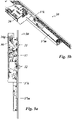
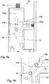
- An embodiment of an active wing lock device 1 mounted in an active wing 10 of a double-leaf door is in the Figures 1a to 1c shown in your interaction with an associated passive wing lock device, which is mounted in the passive wing 110.
- the non-inventive passive wing lock device 30 of Figures 1a . 1b and 1c has a lock mechanism that is mounted in a lock case 30a.
- the lock case 30a is fitted in a receiving pocket in the passive wing 110.
- the lock mechanism comprises a lock gear with a gear slide 36 which is geared to a lock follower 37 rotatably mounted in the lock case 30a.
- the gear slide 36 is guided vertically in the lock case and can be moved up and down.
- the passive wing lock device 30 comprises an upper and a lower locking rod 380o, 380u and lifting devices 31 and 32 in order to lift the latch 11 and the bolt 12 of an associated active wing lock device, which engage in the passive wing lock device in the locked position.
- the lock gear with the gear slide 36 is used to drive the upper locking bar 380o and the lower locking bar 380u and to drive the lifting devices 31 and 32.
- the design and function of the lifting devices 31 and 32 are explained in detail below in connection with the figures.
- the upper latch bar 380o is coupled to an upper latch bar connector 38o mounted in the upper portion of the lock case 30a.
- This upper connection device 38o is connected to the gear slide 36 via a reversing gear 36g.
- the reversing gear 36g is a toothed gear.
- the upper end piece of the gear slide 36 is designed as a toothed rack and the upper locking rod connection piece 380 also has a toothed rack.
- a toothed wheel device is rotatably mounted in a rotary bearing fixed to the lock housing.
- the toothed wheel device meshes with the toothed racks of gear slide 36 and locking rod connection device 38o, which are linearly guided in the vertical direction in the lock housing.
- the two racks are aligned in parallel facing each other with gear means interposed so that the two racks move in opposite directions in the vertical direction. This means that when the gear slide 36 is moved upwards, the upper locking rod connection device 38o is moved down and the locking rod connection device 38o is moved up by moving the gear slide 36 downwards.
- the lower locking bar 380u is coupled to a lower locking bar connector 38u mounted in the lower portion of the lock case 30a.
- This lower locking rod connection device 38u is coupled in the same direction to the gear slide 36, so that when the gear slide 36 is moved upwards, the lower locking rod connection device is also moved upwards, and when the gear slide 36 is moved downwards, the locking rod connection device 38u is also moved downwards.
- the locking rods 380o and 380u driven in this way are mounted vertically on the passive wing 110 and are linearly displaceable in each case in a corresponding vertical linear guide, preferably concealed within the passive wing.
- the locking rods 380o and 380u can be moved vertically up and down in opposite directions by their motion-fixed coupling to their associated connection device 38o or 38u via the actuation of the gear slide 36 .
- the upper end of the upper latch bar 380o cooperates with a latch receiving recess formed in the upper post of the door's stationary frame.
- the lower end of the lower latch bar 380u cooperates with a latch receiving recess formed in the floor.
- the free upper end of the locking bar engages in the upper lock receiving recess.
- the free lower end of the latch bar engages the lower latch receiving recess.
- the case lifting device 31 serves to interact with the lock case 11 of the active wing lock device 1.
- the interaction consists in the case lifting device 31 returning the lock case 11 to the lock case 1a of the active wing lock device 1, in which the case Lifting device 31 pressurizes the lock latch 11 and thereby pushes it back until the lock latch 11 is fully inserted into the lock case 1a of the active wing lock device 1 .
- the case-lifting device 31 has a case-actuating slide 31a, which is driven by the gear slide 36 via a lever device 31h.
- the gear slide 36 is pushed upwards, the lever device 31h is swung out so that the latch actuating slide 31a extends.
- the lever device 31h is swiveled in so that the latch actuating slide 31a is retracted again.
- the bolt lifting device 32 is used to unlock and retract the bolt 22 of the active lock device 1.
- the bolt lifting device 32 has a bolt actuating slide 32a in a corresponding manner, which is drive-connected to the gear slide 36 via a lever mechanism 32h.
- the lever device 32h is pivoted out by actuating the gear slide 36, the bolt actuating slide 32a is extended.
- the bolt 22 engaging in the lock case 30a in its extended locking position is unlocked and then retracted into the lock case 1a of the active lock device. Unlocking takes place by applying pressure to the release pin 22a projecting beyond the end face of the bolt 32.
- the bolt 22 After the bolt 22 is unlocked, it is further pressurized, which acts on the front of the bolt 22, retracted into the lock case 1a of the active wing lock device.
- the lever mechanism 32h pivots back, the bolt actuating slide 32a is then retracted. This is done in that the gear slide 36 is moved downwards in the vertical direction.
- a linear guide device 32b of the bolt actuating slide 32a is provided in the lock case 30a.
- the linear guide device 32b is directed horizontally in the lock case 30, so that the bolt actuating slide 32a can be guided in and out horizontally.
- a correspondingly linear guide device can also be designed for the case-actuating slide 31a of the lever device 31 in the lock case 30a, as is the case, for. Tie Figures 6a and 6b is shown for the embodiment shown there.
- the bolt lifting device 32 is also referred to as a bolt unlocking and/or retraction device. You can be designed both for unlocking and for retracting the bolt, as in the Figures 1a , 1b and 1c case shown. In other exemplary embodiments, however, the bolt lifting device 32 can also be designed merely as a bolt retraction device. A separate device or at least a separate unlocking mechanism can be provided for the unlocking, which can optionally also be driven as a time delay by the gear slide 36 via the same lever device 32h or another separate lever device or via another gear. This is particularly true when the bolt 22 is not provided with a release pin mounted in the bolt, ie when another release element, e.g. B. separately from the bolt 22, z. B.
- the bolt lifting device 32 can also be designed merely as an unlocking device, ie the bolt actuating slide 32a can then switch off the locking by applying pressure to the triggering mechanism accordingly.
- the retraction of the bolt can optionally by another mechanism such. B. with a corresponding spring loading of the bolt.
- the spring device in question can be supported on the lock case 1a of the active leaf lock device but also on the passive leaf lock case 1a.
- the case-lifting device 31 is also referred to as a case-unlocking and/or reversing device.
- the spring-loaded lock latch 11 has a prism-shaped end section which has an inlet slope, so that when the active leaf 10 is pulled shut, i.e. when the active leaf 10 is pulled or pushed into the closed position, the lock latch 11 strikes the frame of the passive leaf 110 with the inlet slope and counter to the spring loading the lock latch 11 is retracted.
- the slope of the lock latch 11 facing away from the entry slope is not designed as a slope, but as a blocking surface directed parallel to the plane of the sash, so that active operation of the lock latch 11 is required to open the door or, in a modified version, in which the lock latch 11 is equipped with a Electric strike latch interacts, the electric strike latch is actuated.
- an electric door opener can be arranged in the passive wing lock device. The lock latch 11 can then interact with the door latch and the door can be released from the closed position by electrical actuation of the door latch.
- the lock latch 11 can also be designed as a self-locking lock latch—as a so-called latch bolt.
- the latch bolt can assume three positions, namely a first position retracted into the lock case 1a, a second position extended out of the lock case comparable to the extended position in conventional lock latches and a third position in which the latch bolt is extended far and locked at the same time and/or at least seems locked. In this third position, the latch bolt is about twice as far extended as a conventional lock latch in its extended position. In addition, the latch bolt, as already mentioned, is locked in this far extended third position.
- the case lifting device 31 is designed as a case unlocking and retracting device, ie the case actuating slide 31a serves to unlock the latch bolt 11 in a first phase of the lifting process and to retract the latch bolt in the further course of the lifting process.
- Unlocking takes place in that the release pin 11a, which is movably mounted in the latch bolt, is first retracted by the case actuating slide 31a, ie first the free end of the release pin 11a protruding from the latch bolt 11 in the locked position is retracted by the case actuating slide 31a .
- the retraction unlocks the bolt 11, so that the latch bolt is retracted under further pressure from the latch actuating slide 31a.
- Modified versions with a latch bolt are also possible, in which the latch lifting device 31 is designed only as an unlocking device or only as a retraction device. In these cases, reversing or unlocking can take place via a separate device. The same applies as described above for the bolt lifting device 32 in connection with the unlocking or moving back of the bolt.
- the latch actuating slide 32a has a spring-loaded pressure piece 32c.
- the pressure piece 32c is resiliently supported via a helical compression spring on the plate-shaped base body of the bolt actuating slide 32a.
- the pressure piece 32c like the plate-shaped base body of the bolt actuating slide 32a, is guided horizontally in the linear guide device 32b, which is formed in the lock case 30a.
- the horizontal guide results in a jam-free linear sliding movement and exact positioning of the actuating slide 32a and the pressure piece 32c over the entire travel path and thus a safe, precisely positioned return movement of the bolt 22.
- the spring loading of the pressure piece ensures that the lifting device 32 works properly, even for Versions of double-leaf doors with a relatively large tolerance range with a gap between the passive leaf and the active leaf.
- FIG. 2a and 2 B is a versus the Figures 1a , 1b and 1c modified embodiment not according to the invention shown, in which the case-lifting device 31 is modified.
- the latch actuating slide 31a has an actuating plate which is linked to an actuating lever of the lever mechanism 31b on the driven side.
- the actuating lever has a pivot bearing which is fixed in the lock case 30a and is comparable to the Figures 1a , 1b and 1c actuated by the gear slide 36, but structurally modified in that a pressure pin mounted on the actuating lever is guided in a slot in the gear slide 36.
- a control edge of the gear slide 36 acts together with the pressure pin of the actuating lever, the control edge being formed in the edge contour of the control slide 36 .
- FIGS figures 3a and 3b is a versus the Figures 1a , 1b and 1c modified non-inventive embodiment shown in which the bolt lifting device 32 is modified.
- the bolt actuating slide 32a has a plate-shaped base body which is guided horizontally at the edge in the linear guide device 32b fixed in the lock case 30a.
- the operating lever of the operating gear 32h is similar to that in FIGS figures 2a and 2 B guided in a slot in the gear slide 36 with the pressure pin mounted on the gear lever.
- the bolt-lifting device 32 is structurally similar to the embodiment of FIG figures 3a and 3b .
- the sensor devices are configured to generate the sensor signals.
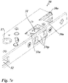
- the case-lifting device 31 is in the embodiment of Figures 6a and 6b and the embodiment of Figures 7a to 7d compared to the embodiments of Figures 1a , 1b and 1c and the figures 2a and 2 B modified in that the latch-lifting device 31 has a sensor device 32t, which is used to detect whether the latch 22 in the lock case 30a of the passive wing lock device is retracted or extended or is being retracted or extended.
- the case-lifting device 31 has as in the Figures 6a and 6b and even better in the Figures 7a to 7d a latch operating slide 31a can be seen, which is guided horizontally with its plate-shaped base body in the linear guide device 31b fixed in the lock case.
- a sensor plate 31tp is displaceably guided in the linear guide device 31b.
- the sensor plate 31tp has two contact plates on its front end edge, which come into contact with the latch 11 .
- the sensor plate 31tp is acted upon outwards by a spring, in the case shown a torsion spring.
- the spring is dimensioned in such a way that when the latch 11 is retracted, it is over-pressed and the latch takes the sensor plate 31tp into abutment with the contact plates.
- the sensor plate 31tp has at its in the Figures 6a and 6b lower edge region has a lateral actuating edge which interacts with the obliquely angled actuating edge of a plate-shaped detection element 31te which is movably mounted in a receptacle which is fixed in the lock case.
- the detection element 31te has an extension which engages in a light sensor 31s arranged in the lock housing 1a when the sensor plate 31tp moves into the lock housing 30a. The retraction and extension of the latch 11 can thus be detected by the sensor device 31t.
- the task and objective of the sensor device 31t is as follows:
- the sensor device 31t has two functions for the lifting process. One function is to ensure that the latch 11 is fully extended out of the lock housing 30a of the passive lock device when retracting, so that the latch 11 cannot impede the opening of the door.
- the other possible function is to ensure that the latch operating slide 31a is not extended too far out of the lock housing 30a when the latch is retracted and to ensure that the latch operating slide 31a thus does not impede the opening and closing of the door.
- the sensor device 31t controls a control device, not shown, of the lifting device 31.
- the control device is controlled via electrical signals which the sensor device 31t emits when the trap is detected and which are fed to the control device.
- z. B. can be monitored via a control center whether the double-leaf door is closed and locked.
- locking monitoring is concerned, this applies to exemplary embodiments in which the latch is designed as a latch bolt and to exemplary embodiments in which a corresponding sensor device is additionally or alternatively provided in the area of the bolt lifting device 32 .
- the sensor device 31t is provided only in the case-lifting device 31 .
- the bolt-lifting device 32 in the exemplary embodiments of the figures provides for the spring loading of the bolt-actuating pressure piece 32c and the prism-shaped design of the bolt-actuating pressure piece 32c for proper functioning.
- the spring loading ensures that the bolt is fully retracted into the lock case 1a of the active wing lock device, in which position it then locks in the lock housing 1a d. H. self-determined is kept.
- the spring loading in connection with the prism shape of the pressure piece then allows the double-leaf door to be opened and closed without the leaves interfering with each other when opening and closing in the area of the closed position, even with a large tolerance range with a gap between the two leaves in the closed position of the door.
- FIG 12 shows a non-inventive embodiment of the passive wing lock device with a sensor device 31s, compared to the sensor device 31t of the embodiment of FIG Figures 7a to 7f is modified.
- the sensor device 31s figure 12 for detecting whether the latch 22 in the lock case 30a of the passive wing lock device is retracted or extended or is currently being retracted or extended.
- the sensor device 31s is composed of a light sensor 31se and a sensor button 31st.
- the light sensor 31se is an optical sensor. It has a U-shaped receptacle into which the free end of the sensor button 31st engages.
- the sensor button is not designed as a slide, but as a two-armed lever.
- the sensor button 31st in figure 12 interacts directly with the light sensor 31se.
- the embodiment of Figures 7a to 7f is provided between the light sensor 31s and the button 31tp and a wedge-shaped transmission member 31te.
- the sensor button 31st of the sensor device in figure 12 is designed as a feeler lever, which is mounted in the lock case so that it can pivot about an axis 31sta that is fixed to the lock case.
- the feeler lever 31st is designed as a two-armed lever.
- the first lever arm 31stt is used here for pressing the lock latch 11 of the active wing lock device.
- the second lever arm 31sts has a hook-like extension that protrudes into the U-shaped receptacle of the light sensor 31s.
- the first lever arm 31stt of the feeler lever 31st protrudes into the predetermined space of the passive wing lock, which is provided for receiving the latch 11 of the active wing lock.
- an in figure 12 spring not shown, is provided, which acts on the feeler lever 31st in the outward direction.
- the sensor device works as follows: When the door is in the closed position, the latch 11 of the active lock device is spring-loaded into the space of the passive wing lock device provided to accommodate the latch 11 .
- the latch 11 comes into contact with the first lever arm 31stt of the feeler lever 31st, so that the feeler lever 31st is pivoted about its axis of rotation 31sta by the latch 11 entering the passive wing lock device.
- the hook-like extension of the sensing lever 31st which protrudes into the light sensor 31s when the door leaf is open, has left the U-shaped receptacle of the light sensor 31se when the latch 11 has reached its closed position.
- the light sensor 31se emits corresponding electrical signals which are processed by an electrical signal processing system.
- the interaction of the sensing lever 31st and the light sensor 32se can also be provided such that the sensing lever 31st engages in the light sensor 31se when the latch 11 is retracted into the receiving space of the passive leaf lock case.
- the hook-like extension of the feeler lever 31st is then outside the receptacle of the light sensor 31.
- the light sensor 31se emits corresponding electrical signals, depending on whether it is actuated or not, which are processed by an electrical signal processing system.
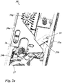
- figure 13 shows an exemplary embodiment of the passive wing lock device with two further sensor devices 32s and 37s, one of which is assigned to the bolt 22 and the other to the lock follower 37.
- the sensor device 32t is used to detect whether the bolt 22 in the lock case 30a of the passive wing lock device is moved in or out or is just being moved in or out.
- This sensor device 32t is constructed analogously to the sensor device 31t figure 12 , which detects the position of the trap.
- the sensor device consists of a light sensor 31se and a sensor button 31st.
- the sensor button 31st is also designed as a two-armed lever which is mounted in the lock case so that it can pivot about an axis 31sta.
- the sensor button 31st has a first lever arm 31stt, which is used to feel the bolt 22, and a second lever arm 31sts on, which interacts with the light sensor 31 se.
- the sensor device 37s serves to detect an actuation of the lock follower 37 .
- a light sensor 37se is provided for this purpose.
- the lock follower 37 has a radially protruding arm 37fs, which is provided with an extension designed as an angled edge. In the rest position of the passive wing lock device, the extension 37fs protrudes into the U-shaped receiving area of the light sensor 37se. If the operating handle on the passive wing lock is actuated by a user, the lock follower 37 is turned. The edge-like extension 37fs of the lock follower 37 then leaves the receiving area of the electric light sensor 37se. The light sensor 37se then emits a corresponding electrical signal which can be processed by electrical signal processing equipment.
- the sensor device 37s can be used to detect whether the passive wing lock was opened by manual actuation of a handle or push rod arranged on the passive wing.
- a sensor device 36s not according to the invention is shown, which is used to detect a movement of the transmission slide 36.
- a light sensor 36se is provided for this purpose.
- the gear slide 36 has a protruding extension 37fs.
- the extension 37f is located outside the U-shaped receiving area of the light sensor 37se. If the passive wing lock is actuated by a user using the actuating handle or by the motorized actuating device, the gear slide 36 is pushed upwards.
- the extension 36fs of the gear slide 36 enters the receiving area of the electric light sensor 36se.
- the light sensor 36se then emits a corresponding electrical signal which can be processed by electrical signal processing equipment.
- the sensor device 37t can be used to detect whether the passive wing lock was opened by manual actuation of a handle or push rod arranged on the passive wing.
- the sensors 31se, 32se, 36se and 37se are mounted on a circuit board that is mounted in the lock case.
- an electronic device is provided for evaluating and/or further processing the data from the sensors.
- This electronic device can be arranged in a separate housing. This separate housing can be arranged adjacent to the lock case, preferably coupled.
- the circuit board on which the sensors are arranged is electrically connected to the electronic device.
- electrical cable connections can be provided for this purpose, via which the circuit board is connected to the electronic device arranged in the separate housing.
- a control center can monitor in a public building whether a double-leaf door is open or in the closed position or locked. Furthermore, a monitoring center can determine whether a door was unlocked by actuating the follower or by activating the motorized actuating device.
- the position of the lock nut remains unchanged and the signal from the sensor 37s also remains unchanged, while unlocking by actuating the handle causes the lock nut 37 to rotate and is detected by the sensor 37s assigned to the nut.
- the sensors can also be used to control the motorized actuation device when the lock device is unlocked.
- the sensors 31se and 32se can be used to detect during unlocking whether the latch 11 or the bolt 22 no longer protrudes into the associated receptacles of the passive wing lock, whereupon the motorized actuating device can be deactivated.
- the passive wing lock device 30 can be actuated via a manual actuation device, which is not shown in the figures.
- the manual actuating device can be designed as a rotary handle that can be inserted into the lock follower 37, the lock follower 37 representing a part of the lock mechanism.
- the rotary handle can be designed as a conventional pusher or as a push bar, a so-called panic push bar. Both the handle and the push rod can have a corresponding rotating connection, which can be plugged into the lock follower 37 in a rotationally fixed manner for coupling to the lock gear.
- the lock follower 37 By actuating the actuating device, the lock follower 37 is rotated and the lock mechanism is thereby actuated.
- the gear slide is moved.
- the locking rod connecting devices 38o, 38u are displaced vertically in opposite directions, depending on the direction of rotation of the actuation.
- the latch lifting device 31 and the bolt lifting device 32 are also actuated simultaneously or with a time delay.
- the lock mechanism is designed in such a way that an actuation of the lock follower 37 in one direction moves the upper locking rod connection device 38o upwards and the lower locking rod connection device 38u downwards, and consequently the relevant locking rods 380o and 380u are each extended, i.e. moved into their locking position will.
- the lifting devices 31, 32 for lifting the latch 11 and the bolt 12 are actuated via the lock gear in such a way that the latch actuating slide 31a and the bolt actuating slide 32a are retracted into the lock housing 30a of the passive lock device 30.
- the locking rod connection devices 38o, 38u move in the opposite direction, as a result of which the locking rods 380o, 380u are retracted, i.e. the locking rods are unlocked and the lifting devices 31 and 32 are extended to release the bolt 22 and retract the case 11 of the active lock device into the lock case of the active lock device.
- a corresponding motorized actuating device with rotary output can also be coupled to the lock follower 37 .
- the lock follower 37 is rotated in a corresponding manner by this motorized actuating device and the lock gear is actuated, so that the two locking bar connection devices 38o, 38u and the lifting devices 31, 32 are actuated in the same way.
- a motorized actuating device can also be used, which, in contrast to this, has a linear output.
- the linear output can be coupled directly to the gear slide 36 .
- the actuation of the lock gear by the linear output of the motorized actuation device then acts in the same way as when the lock gear is actuated by rotating the lock follower 37, as described above.
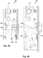
- the Figures 5a and 5b show a non-inventive passive leaf lock device 30 with such a motorized actuating device 37m arranged at the lower end of the lock case 30a.
- the motorized actuating device 37m is coupled to the lock mechanism via a coupling slide 37k, which is coupled with one end to the linear output of the motorized actuating device 37m and with its other end to the geared slide 36 of the lock mechanism so that it cannot move.
- Figures 5c and 5d show the clutch slide 37k coupled to the transmission slide, without the motorized actuating device 37m being coupled.
- the configuration with the motorized actuation device can be optional.
- manipulation protection devices are provided in the exemplary embodiments illustrated in the figures.
- the manipulation protection devices are intended to prevent the locking rods from being able to be retracted as a result of pressure being applied to the locking rod 380o and/or 380u from the outside.
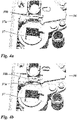
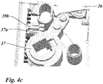
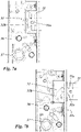
- Anti-tamper device is in the Figures 4a, 4b and 4c shown.
- a blocking member 39b is movably mounted in the lock housing 30a and blocks displacement of the locking bar in the retraction direction when external pressure is applied, in that the blocking member 39b engages in a recess 36a in the gear slide 36 in its blocking position.
- Figure 4a shows the position before a manipulation attempt is made by external pressure being applied to the locking rods 380o, 380u.
- Figure 4b shows the blocking member 39b in the blocking position during an attempt at manipulation.
- the gear slide 36 is manipulated by applying pressure to the locking bars from the position in Figure 4a moved up a little and is held against further upward displacement by the blocking member 39b.
- Figure 4c shows the blocking member 39b in the release position, in which it is disengaged from the gear slide 36.
- the blocking member 39b is shifted into this release position by the actuation of the lock nut 37 in that, by rotating the lock nut 37 counterclockwise in the illustration in the figure, the driver 37a fixed to the lock nut 37 interacts with the blocking member 39b and the blocking member 39b in the representation in the Figure 4c shifted to the left.
- This first embodiment of the anti-tamper device in the Figures 4a to 4c thus acts on the gear slide 36 and thus on both locking bars; however, it requires an actuating device on the lock follower 37.
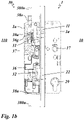
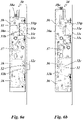
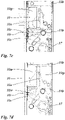
- An inventive design of a tamper protection device is in the Figures 9a and 9b shown. This anti-tampering device does not require actuation of the lock mechanism via the lock follower 37, but the actuation of the lock mechanism can also be carried out via a linear output of the geared slide, for example via the motorized actuating device 37m Figures 5a and 5b take place.
- This version of the anti-tamper device looks in the embodiment of Figures 9a and 9b a connecting link device 39k, which is formed between the upper locking rod connection device 38o and the gear slide 36.
- the link device 39k has a link slot 39ok, which is formed with the plate-shaped main body of the upper locking rod connection device 38o.
- the link device 39k also has a lever 39h, which is mounted in a pivot bearing fixed to the lock case and has a link pin at one end, which engages in the link slot 39ok and at its other end has a guide pin, which engages in a slot in the gear slide 36 is formed.
- Link slot 39ok is formed as an angled slot with an upper vertical branch and a lower horizontal branch. In the event of an attempt at manipulation, the link pin 39s moves into the upper vertical branch of link slot 39ok and blocks vertical movement of upper locking rod connection device 38o (see Figure 9a ). As a result, no manipulation movement is transmitted to the gear slide 36 .
- the link device 39k described above thus forms the above-described embodiment of the invention Figures 9a and 9b an anti-tamper device for the top latch bar 380o.
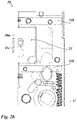
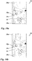
- a manipulation protection device is provided, as is shown in FIGS Figures 10a and 10b is shown.
- This manipulation protection device has a blocking lever 39p, which is mounted in a pivot bearing fixed to the lock case. He is gravity fed into the in Figure 10a with its free end pointing to the left. In this position, a blocking pin 39s fixed in motion with the gear slide 36 engages in the hook-shaped recess of the blocking lever 39p.
- Figure 10c shows the situation in the event of a manipulation attempt.
- the plate-shaped base body of the lower locking rod connection device 38u is guided upwards in the elongated holes by the pressure exerted on the locking rod 380u and comes into contact with the lower base of the blocking lever 39p. In this way, displacement of the lower locking bar 380u in an attempt at manipulation is counteracted and the lower locking bar 380u is blocked in the extended position. The vertical movement of the lower bolt connection device 38a is thus not transmitted to the gear slide 36.
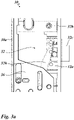
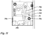
- figure 11 shows a non-inventive embodiment of the passive wing lock device with a manipulation protection device for the lower locking bar 380u, wherein the manipulation protection device according to figure 11 against the anti-tamper device according to Figures 10a to 10c is modified.
- the tamper protection device has a blocking lever 39p, which is mounted in a pivot bearing fixed to the lock case.
- the blocking lever has a blocking stop 39b which, in the blocking position, interacts with the lower locking rod connecting device 38u, as shown in FIG figure 11 is shown.
- the blocking stop 39b is formed as a stop step of the side edge of the blocking lever 39p.
- the manipulation attempt is in figure 11 shown.
- figure 11 shows the protection against tampering in the event of a tampering attempt.
- the protection against tampering consists in the fact that when pressure is exerted on the lower locking rod connection device 38u, the lower locking rod connection device 38u comes into the stop position on the blocking stop 39b of the blocking lever 39p and is thus blocked against further displacement in the vertical direction upwards. As a result, no vertical movement is transmitted to the gear slide 36 through the lower locking rod connecting device 38u.
- the blocking lever 39p is provided with a link slot into which a link pin 36k of the gear slide 36 engages. If, in the case of a proper unlocking by actuating the nut 37 or the motorized actuating device 37m, the gear slide 36 is pushed upwards for unlocking, the pin 36k fixed to the gear slide moves vertically upwards and runs in the link slot 39k of the blocking lever, whereby the blocking lever 39p is pivoted counterclockwise in the case shown. When pivoted, the blocking lever 39p then no longer protrudes in a blocking manner into the range of motion of the lower locking rod connection device 38u. Simultaneously with the pivoting of the locking lever 39p, a lever 38h is pivoted.
- the lever 38h is mounted in the lock case 38a such that it can pivot about an axis 38a fixed to the lock case and interacts with an actuating stop arranged on the gear slide 36 at the foot end.
- the lever 38h is designed as an actuating lever for the lower locking rod connection device 38u. Its free end interacts with a corresponding stop on the lower locking rod connection device 38u.
- the lower locking rod connecting device 38u is thus moved in the same direction as the gear slide 36 and the lower locking rod is retracted into the lock case.
Description
Die Erfindung betrifft eine Passivflügel-Schlosseinrichtung für eine Tür, ein Fenster oder dergleichen. Die Tür weist einen ortsfesten montierbaren Rahmen mit in dem Rahmen gelagerten mindestens einem aktiven Flügel und mindestens einem passiven Flügel auf. Es handelt sich also um eine zweiflügelige Tür. Der Aktivflügel wird im Folgenden als Aktivflügel bezeichnet. Der passive Flügel wird im Folgenden als Passivflügel bezeichnet.The invention relates to a passive wing lock device for a door, a window or the like. The door has a stationary mountable frame with at least one active wing and at least one passive wing mounted in the frame. It is therefore a double-leaf door. The active wing is referred to below as the active wing. The passive wing is referred to below as the passive wing.
Die Passivflügel-Schlosseinrichtung ist in oder auf dem Passivflügel montierbar. Sie weist eine Schlossmechanik und eine Betätigungseinrichtung zur Betätigung der Schlossmechanik auf. Die Schlossmechanik weist eine Riegelstangen-Anschlusseinrichtung einer in oder auf dem Passivflügel geführten oberen Riegelstange auf, wobei die obere Riegelstange zum Verriegeln nach oben ausfahrbar und zum Entriegeln nach unten einfahrbar ist. Zusätzlich oder alternativ weist die Schlossmechanik eine unterer Riegelstangen-Anschlusseinrichtung einer in oder auf dem Passivflügel geführten unteren Riegelstange auf, wobei die untere Riegelstange zum Verriegeln nach unten ausfahrbar und zum Entriegeln nach oben einfahrbar ist.The passive wing lock device can be installed in or on the passive wing. It has a lock mechanism and an actuating device for actuating the lock mechanism. The lock mechanism has a locking bar connection device for an upper locking bar guided in or on the passive leaf, with the upper locking bar being able to be extended upwards for locking and retracted downwards for unlocking. Additionally or alternatively, the lock mechanism has a lower locking bar connection device for a lower locking bar guided in or on the passive leaf, the lower locking bar being able to be extended downwards for locking and retracted upwards for unlocking.
Der Erfindung liegt die Aufgabe zu Grunde eine Passivflügel-Schlosseinrichtung zu schaffen, die eine Manipulationsschutzeinrichtung aufweist, die einem Einfahren der Riegelstangen in Folge einer von außen einwirkenden Druckbeaufschlagung auf die Riegelstangen entgegenwirkt.The invention is based on the object of creating a passive wing lock device which has a manipulation protection device which counteracts retraction of the locking rods as a result of pressure being applied to the locking rods from outside.
Die Erfindung löst diese Aufgabe mit den Gegenständen der Patentansprüche 1 und 7.The invention solves this problem with the subject matter of patent claims 1 and 7.
Bei dem Gegenstand des Patentanspruchs 1 ist wesentlich, dass die obere Riegelstangen-Anschlusseinrichtung oder dass die untere Riegelstangen-Anschlusseinrichtung mit dem Schlossgetriebe über eine Kulisseneinrichtung verbunden ist, und dass die Kulisseneinrichtung einen Kulissenführungsschlitz und einen Kulissenstift aufweist, der in dem Kulissenführungsschlitz geführt ist und in einem Fangabschnitt des Kulissenführungsschlitzes im Manipulationsfall blockiert ist.In the case of the subject matter of patent claim 1, it is essential that the upper locking rod connection device or that the lower locking rod connection device is connected to the lock gear via a link device, and that the link device has a link guide slot and a link pin, which is guided in the link guide slot and in a catch section of the link guide slot is blocked in the event of manipulation.
Bei bevorzugten Ausführungen kann vorgesehen sein, dass das Schlossgetriebe einen Getriebeschieber aufweist, der zum Antrieb der oberen Riegelstangen-Anschlusseinrichtung zwischen der oberen Riegelstangen-Anschlusseinrichtung und der Schlossbetätigungseinrichtung geschaltet ist, wobei die Kulisseneinrichtung zwischen der oberen Riegelstangen-Anschlusseinrichtung und dem Getriebeschieber geschaltet ist. Es kann vorgesehen sein, dass das Schlossgetriebe einen Getriebeschieber aufweist, der zum Antrieb der unteren Riegelstangen-Anschlusseinrichtung und der Schlossbetätigungseinrichtung geschaltet ist, wobei die Kulisseneinrichtung zwischen der unteren Riegelstangen-Anschlusseinrichtung und dem Getriebeschieber geschaltet ist.In preferred embodiments, it can be provided that the lock gear has a gear slide, which is connected between the upper lock rod connection device and the lock actuating device to drive the upper locking rod connection device, with the slotted link device being connected between the upper lock rod connection device and the gear slide. Provision can be made for the lock gear to have a gear slide which is connected to drive the lower locking rod connection device and the lock actuating device, the link device being connected between the lower locking rod connection device and the gear slide.
Bei bevorzugten Ausführungen kann vorgesehen sein, dass zwischen der oberen oder der unteren Riegelstangen-Anschlusseinrichtung - im Folgenden als die besagte Riegelstangen Einrichtung bezeichnet - und dem Getriebeschieber ein die Bewegungsrichtung umkehrendes Getriebe geschaltet ist. Hierbei ist vorgesehen, dass die Kulisseneinrichtung zwischen dem die Bewegungsrichtung umkehrenden Getriebe und der besagten Riegelstangen-Anschlusseinrichtung geschaltet ist; oder dass die Kulisseneinrichtung zwischen dem Getriebeschieber und dem die Bewegungsrichtung umkehrenden Getriebe geschaltet ist.In preferred embodiments, it can be provided that between the upper or the lower locking bar connecting device—hereinafter referred to as said locking bar device—and the gear slide, a gear reversing the direction of movement is connected. Here it is provided that the connecting link device is connected between the gear mechanism that reverses the direction of movement and the said locking rod connection device; or that the connecting link device is connected between the gear slide and the gear reversing the direction of movement.
Für den Fall, dass die Kulisseneinrichtung zwischen dem die Bewegungsrichtung umkehrenden Getriebe und der besagten Riegelstangen-Anschlusseinrichtung geschaltet ist, kann vorgesehen sein, dass zur Verbindung der Kulisseneinrichtung mit dem die Bewegungsrichtung umkehrenden Getriebe und der besagten Riegelstangen-Anschlusseinrichtung der Kulissenschlitz mit dem die Bewegungsrichtung umkehrenden Getriebe und der Kulissenstift mit der besagten Riegelstangen-Anschlusseinrichtung verbunden ist; oder der Kulissenstift mit dem die Bewegungsrichtung umkehrenden Getriebe und der Kulisschenschlitz mit der besagten Riegelstangen-Anschlusseinrichtung verbunden ist.In the event that the link device is connected between the gear mechanism that reverses the direction of movement and the said locking rod connection device, it can be provided that, in order to connect the link device to the gear mechanism that reverses the direction of movement and the said locking rod connection device, the link slot can be connected to the slot that reverses the direction of movement gear and link pin connected to said latch bar connector; or the link pin is connected to the reversing gear and the link slot is connected to said latch bar connector.
Für den Fall, dass die Kulisseneinrichtung zwischen dem Getriebeschieber und dem die Bewegungsrichtung umkehrenden Getriebe geschaltet ist, kann vorgesehen sein, dass zur Verbindung der Kulisseneinrichtung mit dem Getriebeschieber und dem die Bewegungsrichtung umkehrenden Getriebe der Kulissenschlitz mit dem Getriebeschieber und der Kulissenstift mit dem die Bewegungsrichtung umkehrenden Getriebe, oder der Kulissenstift mit dem Getriebeschieber und der Kulissenschlitz mit dem die Bewegungsrichtung umkehrenden Getriebe verbunden ist.In the event that the link device is connected between the gear slide and the gear that reverses the direction of movement, it can be provided that, in order to connect the link device to the gear slide and the gear that reverses the direction of movement, the link slot should be connected to the gear slide and the link pin to the gear that reverses the direction of movement Gears, or the link pin is connected to the gear slide and the link slot is connected to the gear reversing the direction of movement.
Bei bevorzugten Ausführungen kann vorgesehen sein, dass die Kulisseneinrichtung derart ausgebildet ist, dass sie in ihrer Blockierstellung nicht blockierend auf das Schlossgetriebe einwirkt, über welches die Riegelstange betätigbar ist.In preferred embodiments, it can be provided that the connecting link device is designed in such a way that, in its blocking position, it does not have a blocking effect on the lock mechanism, via which the locking bar can be actuated.
Bei bevorzugten Ausführungen kann vorgesehen sein, dass das Blockierelement als Blockierhebel ausgebildet ist, der in einem im Schlosskasten der Passivflügel-Schlosseinrichtung festen Lager schwenkbar gelagert ist oder als Blockierschieber ausgebildet ist, der in einer im Schlosskasten festen Führungseinrichtung verschiebbar gelagert ist.In preferred embodiments it can be provided that the blocking element is designed as a blocking lever which is pivotably mounted in a bearing fixed in the lock case of the passive leaf lock device or is designed as a blocking slide which is slidably mounted in a guide device fixed in the lock case.
Bei bevorzugten Ausführungen kann vorgesehen sein, dass das Blockierelement durch Schwerkraft in Blockierrichtung beaufschlagt ist und mit einem Getriebeelement des mit dem Schlossgetriebe festen Mitnehmers derart zusammenwirkt, dass der Blockierhebel entgegen der Schwerkraft in Freigaberichtung dreht, wenn das Getriebeelement, vorzugsweise Getriebeschieber des Schlossgetriebes in die Entriegelungsrichtung verschoben wird.In preferred embodiments, it can be provided that the blocking element is acted upon by gravity in the blocking direction and interacts with a gear element of the driver fixed to the lock gear in such a way that the blocking lever rotates counter to gravity in the release direction when the gear element, preferably the gear slide of the lock gear, is in the unlocking direction is postponed.
Bei bevorzugten Ausführungen kann vorgesenen sein, dass das Blockierelement unmittelbar oder mittelbar mit einem mit dem Getriebeschieber des Schlossgetriebes festen Mitnehmer zusammenwirkt.In preferred embodiments it can be provided that the blocking element interacts directly or indirectly with a driver that is fixed to the gear slide of the lock gear.
Bei bevorzugten Ausführungen kann vorgesehen sein, dass das im Schlosskasten bewegbar gelagerte Blockierelement so ausgebildet ist, dass es im Falle einer Manipulationsdruckbeaufschlagung der unteren und/oder oberen Riegelstange unmittelbar den Getriebeschieber blockiert, ohne dass das Blockierelement unmittelbar auf die untere und/oder die obere Riegelstangen-Anschlusseinrichtung einwirkt.In preferred embodiments, it can be provided that the blocking element, which is movably mounted in the lock case, is designed in such a way that in the event of manipulation pressure being applied to the lower and/or upper locking bar, it directly blocks the gear slide without the blocking element directly impacting the lower and/or upper locking bar -Connection device acts.
Bei bevorzugten Ausführungen kann vorgesehen sein, dass das Blockierelement in einem im Schlosskasten festen Lager bewegbar gelagert ist und mit einem Getriebeelement des Schlossgetriebes, vorzugsweise einem Getriebeschieber, in einer Blockierstellung blockierend zusammenwirkt und in seiner Freigabestellung außer Eingriff dieses Getriebeelements angeordnet ist, wobei das Blockierelement unter Einwirkung der Schlossbetätigungseinrichtung von der Blockierstellung in die Freigabestellung verlagerbar ist.In preferred embodiments, it can be provided that the blocking element is movably mounted in a bearing fixed in the lock case and interacts with a gear element of the lock gear, preferably a gear slide, in a blocking position and in its release position is arranged disengaged from this gear element, the blocking element being under Effect of the lock actuator from the blocking position to the release position can be displaced.
Bei bevorzugten Ausführungen kann vorgesehen sein, dass das Schlossgetriebe ein Getriebeelement aufweist, das als Getriebeschieber ausgebildet ist, der an seinem einen Ende mit der unteren Riegelstangen-Anschlusseinrichtung und an seinem anderen Ende mit der oberen Riegelstangen-Anschlusseinrichtung jeweils zumindest getriebemäßig verbunden ist. Hierbei ist zwischen dem Getriebeschieber und der oberen Riegelstangen-Anschlusseinrichtung ein die Bewegungsrichtung umkehrendes Getriebe geschaltet. Alternativ ist zwischen dem Getriebeschieber und der unteren Riegelstangen-Anschlusseinrichtung ein die Bewegungsrichtung umkehrendes Getriebe geschaltet.In preferred embodiments it can be provided that the lock gear has a gear element which is designed as a gear slide which is connected at least in terms of gearing at one end to the lower locking rod connection device and at its other end to the upper locking rod connection device. In this case, a gear reversing the direction of movement is connected between the gear slide and the upper locking rod connection device. Alternatively, a gear that reverses the direction of movement is connected between the gear slide and the lower locking rod connection device.
Wesentlich ist hierbei, dass die Schlossbetätigungseinrichtung über ein Getriebe der Schlossmechanik im Folgenden als Schlossgetriebe bezeichnet, auf die obere Riegelstangen Anschlusseinrichtung und/oder auf die untere Riegelstangen Anschlusseinrichtung einwirkt, um die Riegelstangen ordnungsgemäß zu betätigen, dass jedoch die obere Riegelstangen Anschlusseinrichtung und/oder die untere Riegelstangen Anschlusseinrichtung eine Manipulationsschutzeinrichtung aufweist bzw. aufweisen, die einem Einfahren der oberen bzw. der unteren Riegelstange durch Druckbeaufschlagung des freien Endes entgegenwirkt.It is essential here that the lock actuating device acts on the upper locking rod connection device and/or on the lower locking rod connection device via a gear of the lock mechanism, hereinafter referred to as the lock gear, in order to actuate the locking rods properly, but that the upper locking rod connection device and/or the lower locking rods connecting device has or have a tamper protection device which counteracts retraction of the upper or lower locking rod by pressurizing the free end.
Was die obere Riegelstangen-Anschlusseinrichtung betrifft, kann die Manipulationsschutzeinrichtung einem Einfahren der oberen Riegelstange in Folge einer Druckbeaufschlagung des freien Endes der oberen Riegelstange dadurch entgegenwirken, dass im Falle einer derartigen Manipulationsdruckbeaufschlagung der oberen Riegelstange die obere Riegelstange in Einfahrrichtung blockiert wird, in dem die Manipulationsschutzeinrichtung das Schlossgetriebe und/oder die obere Riegelstangen-Anschlusseinrichtung blockiert.As far as the upper locking bar connection device is concerned, the tamper protection device can counteract retraction of the upper locking bar as a result of pressure being applied to the free end of the upper locking bar by blocking the upper locking bar in the retraction direction in the event of such manipulation pressure being applied to the upper locking bar, in which the tamper protection device the lock mechanism and/or the upper locking bar connection device is blocked.
Was die untere Riegelstangen-Anschlusseinrichtung betrifft, kann die Manipulationsschutzeinrichtung einem Einfahren der unteren Riegelstange durch Druckbeaufschlagung des freien Endes der unteren Riegelstange dadurch entgegenwirke, dass im Falle einer derartigen Manipulationsdruckbeaufschlagung der unteren Riegelstange die untere Riegelstangen Einfahreinrichtung blockiert wird, indem die Manipulationsschutzeinrichtung das Schlossgetriebe und/oder die untere Riegelstangen-Anschlusseinrichtung blockiert.As far as the lower locking bar connection device is concerned, the anti-tamper device can counteract retraction of the lower locking bar by pressurizing the free end of the lower locking bar by blocking the lower locking bar retraction device in the event of such tampering pressure being applied to the lower locking bar by the anti-tamper device locking the lock gear and/or or the lower locking bar connection device is blocked.
Für den Aufbau und die Funktionsweise der erfindungsgemäßen Manipulationsschutzeinrichtungen sieht die Erfindung zwei Grundsatzausführungen vor:The invention provides two basic versions for the construction and functioning of the anti-tamper devices according to the invention:
Dieser Gegenstand sieht zusätzlich oder alternativ das Ausführungsprinzip Nr. 1 auch für die untere Riegelstange vor und zwar dadurch, dass die Manipulationsschutzeinrichtung ein im Schlosskasten bewegbar gelagertes Blockierelement aufweist, das im Falle einer Manipulationsdruckbeaufschlagung der unteren Riegelstange vorzugsweise unmittelbar die untere Riegelstangen-Anschlusseinrichtung blockiert, ohne dass das Blockierelement unmittelbar auf das Schlossgetriebe einwirkt. Ein spezielles Ausführungsbeispiel, das dementsprechend ausgeführt ist, ist in
Bei dem Ausführungsprinzip Nr. 1 ergeben sich besondere Vorteile, wenn vorgesehen ist, dass das Blockierelement als Blockierhebel ausgebildet ist, der in einem im Schlosskasten festen Lager schwenkbar ist und dass die untere Riegelstangen-Anschlusseinrichtung mit einem Getriebeelement des Schlossgetriebes, vorzugsweise einem Getriebeschieber, verriegelungsfest verbunden ist. In diesem Zusammenhang kann vorgesehen sein, dass die untere Riegelstangen-Anschlusseinrichtung und das Getriebeelement über den Blockierhebel kuppelbar ist und dass im Falle der Manipulationsdruckbeaufschlagung des unteren Endes der unteren Riegelstange in Einfahrrichtung der Blockierhebel die untere Riegelstangenanschlusseinrichtung in Richtung gegen eine Schiebebewegung nach oben blockiert; dies ist bei dem Ausführungsbeispiel der
Bei abgewandelten Ausführungen kann diese Gestaltung entsprechend für die obere Riegelstange vorgesehen sein. Dies bedeutet, dass bei diesen Ausführungen das Blockierelement als Blockierhebel ausgebildet ist, der in einem im Schlosskasten festen Lager schwenkbar gelagert ist und dass die obere Riegelstangeneinrichtung mit einem Getriebeelement des Schlossgetriebes, vorzugsweise einem Getriebeschieber bewegungsfest verbunden ist. Hierbei kann die obere Riegelstangen-Anschlusseinrichtung und das Getriebeelement über den Blockierhebel kuppelbar sein und im Falle der Manipulationsdruckbeaufschlagung des oberen Endes der oberen Riegelstange in Einfahrrichtung der Blockierhebel die obere Riegelstangen-Anschlusseinrichtung gegen eine Schiebebewegung nach unten blockieren.In modified versions, this design can be provided accordingly for the upper locking bar. This means that in these designs the blocking element is designed as a blocking lever which is pivotally mounted in a bearing fixed in the lock case and that the upper locking rod device is connected to a gear element of the lock gear, preferably a gear slide, so that it cannot move. In this case, the upper locking rod connection device and the gear element can be coupled via the blocking lever and, in the event of manipulation pressure being applied to the upper end of the upper locking rod in the retraction direction of the blocking lever, the upper locking rod connection device can be blocked against a downward sliding movement.
In den genannten Ausführungen kann der Blockierhebel vorzugsweise durch Schwerkraft in Blockierrichtung beaufschlagt sein und mit dem Getriebeelement des Schlossgetriebes, vorzugsweise dem getriebeschieberfesten Mitnehmer direkt zusammenwirken. Der Blockierhebel kann entgegen der Schwerkraft in Freigaberichtung drehen, wenn das Getriebeelement, vorzugsweise der Getriebeschieber in die Entriegelungsrichtung verschoben wird.In the embodiments mentioned, the blocking lever can preferably be acted upon by gravity in the blocking direction and interact directly with the transmission element of the lock mechanism, preferably the driver fixed to the transmission slide. The blocking lever can rotate against the force of gravity in the release direction when the gear element, preferably the gear slide, is displaced in the unlocking direction.
Das Ausführungsprinzip Nr. 2 sieht eine Kulissenführung vor, die zwischen dem Schlossgetriebe einerseits und er oberen Riegelstangen Anschlusseinrichtung und/oder der unteren Riegelstangen Anschlusseinrichtung andererseits einwirkt. Es kann hierzu vorgesehen sein, dass die obere Riegelstangen Anschlussseinrichtung mit dem Schlossgetriebe, vorzugsweise einem Getriebeschieber des Schlossgetriebes über eine Kulisseneinrichtung verbunden ist. Es kann aber auch vorgesehen sein, dass die untere Riegelstangen Anschlusseinrichtung mit dem Schlossgetriebe, vorzugsweise dem Getriebeschieber des Schlossgetriebes, über eine Kulisseneinrichtung verbunden ist. Es kann eine Ausführung der Kulisseneinrichtung für ein Zusammenwirken zwischen der oberen Riegelstangen Anschlusseinrichtung und dem Schlossgetriebe bzw. zwischen der unteren Riegelstangen Anschlusseinrichtung und dem Schlossgetriebe vorgesehen sein. Diesen Ausführungen ist gemäß einer Ausführung a der Kulissenschlitz bewegungsfest mit der betreffenden Riegelstangen Anschlusseinrichtung und der Kulissenstift über ein Umkehrgetriebe mit dem Getriebeschieber verbunden. Gemäß einer Ausführung b ist der Kulissenschlitz bewegungsfest mit dem Schlossgetriebe und der Kulissenstift über ein Umkehrgetriebe mit der betreffenden Riegelstangen Anschlusseinrichtung verbunden. Design principle no. 2 provides a link guide which acts between the lock mechanism on the one hand and the upper locking rod connection device and/or the lower locking rod connection device on the other hand. For this purpose, it can be provided that the upper locking rod connecting device is connected to the lock mechanism, preferably a gear slide of the lock mechanism, via a connecting link mechanism. However, it can also be provided that the lower locking rod connection device is connected to the lock gear, preferably the gear slide of the lock gear, via a connecting link device. An embodiment of the connecting link device can be provided for cooperation between the upper locking rod connection device and the lock mechanism or between the lower locking rod connection device and the lock mechanism. According to one embodiment a of these designs, the link slot is connected to the relevant locking rod connection device in a non-moving manner and the link pin is connected to the gear slide via a reversing gear. According to an embodiment b, the link slot is connected to the lock gear so that it cannot move, and the link pin is connected to the locking rod connection device in question via a reversing gear.
Es kann die obere Riegelstangen-Anschlusseinrichtung bzw. die untere Riegelstangen-Anschlusseinrichtung über eine Kulisseneinrichtung mit dem Schlossgetriebe verbunden sein. Gemäß einer Ausführung a ist der Kulissenstift bewegungsfest mit der betreffenden Riegelstangen-Anschlusseinrichtung verbunden und der Kulissenschlitz in einem Umkehrgetriebe der oberen Riegelstangen-Anschlusseinrichtung angeordnet. Gemäß einer Ausführung b ist der Kulissenstift bewegungsfest mit dem Schlossgetriebe verbunden und der Kulissenstift in einem Umkehrgetriebe der oberen Riegelstangen-Anschlusseinrichtung ausgebildet.The upper locking bar connection device or the lower locking bar connection device can be connected to the lock mechanism via a connecting link device. According to an embodiment a, the link pin is connected to the locking rod connection device in question in such a way that it cannot move, and the link slot in one Arranged reversing gear of the upper locking rod connection device. According to an embodiment b, the link pin is connected to the lock gear so that it cannot move, and the link pin is formed in a reversing gear of the upper locking rod connection device.
Das genannte Umkehrgetriebe kann bei den Ausführungen jeweils als eine Hebeleinrichtung ausgebildet sein, die in einem im Schlosskasten festen Drehlager gelagert ist.In each of the embodiments, the reversing gear mentioned can be designed as a lever device that is mounted in a pivot bearing that is fixed in the lock case.
Bei den genannten diversen Ausführungen, ist das Schlossgetriebe vorzugsweise als ein Getriebe mit einem Getriebeschieber ausgebildet, d.h. das genannte Getriebeelement ist als Getriebeschieber ausgebildet, der an seinem einen Ende mit der unteren Riegelstangen-Anschlusseinrichtung und an seinem anderen Ende mit der oberen Riegelstangen-Anschlusseinrichtung jeweils zumindest getriebemäßig verbunden ist und zum Entriegeln der unteren und der oberen Riegelstange in eine erste Richtung verschiebbar und zum Verriegeln und der unteren und der oberen Riegelstange in eine zweite Richtung verschiebbar ist. Diese erste Richtung ist der zweite Richtung um 180° entgegengesetzt ausgebildet. Hierfür ist zwischen dem Getriebeschieber entweder zum Anschluss zur oberen Riegelstangen-Anschlusseinrichtung oder zum Anschluss zur unteren Riegelstangen-Anschlusseinrichtung ein Umkehrgetriebe ausgebildet.In the various designs mentioned, the lock gear is preferably designed as a gear with a gear slide, i.e. the named gear element is designed as a gear slide, which is connected at one end to the lower locking bar connection device and at its other end to the upper locking bar connection device is at least gearedly connected and is slidable in a first direction to unlock the lower and upper latch bars and slidable in a second direction to lock and latch the lower and upper latch bars. This first direction is 180° opposite to the second direction. For this purpose, a reversing gear is formed between the gear slide either for connection to the upper locking rod connection device or for connection to the lower locking rod connection device.
Bestimmte Ausführungen sehen vor, dass die Schlossmechanik der Passivflügel-Schlosseinrichtung eine Fallen-Aushebeeinrichtung aufweist zum Entriegeln und/oder zum Zurückfahren einer Falle, nämlich Schlossfalle oder Fallenriegel einer in und/oder auf dem Aktivflügel montierbaren Aktivflügel-Schlosseinrichtung. Zusätzlich oder alternativ kann die Schlossmechanik auch eine Riegelaushebeeinrichtung aufweisen zum Entriegeln und/oder Zurückfahren eines Riegels einer in und/oder auf Aktivflügel montierbaren Aktivflügel-Schlosseinrichtung. Vorzugsweise sind die Aushebeeinrichtungen mit derselben Schlossbetätigungsmechanik betätigbar, mit der auch die obere Riegelstange und die untere Riegelstange betätigt werden.Certain versions provide that the lock mechanism of the passive leaf lock device has a latch lifting device for unlocking and/or retracting a latch, namely a lock latch or latch bolt of an active leaf lock device that can be mounted in and/or on the active leaf. Additionally or alternatively, the lock mechanism can also have a bolt lifting device for unlocking and/or retracting a bolt of an active leaf lock device that can be mounted in and/or on the active leaf. The lifting devices can preferably be actuated with the same lock actuating mechanism with which the upper locking bar and the lower locking bar are also actuated.
Von besonderem Vorteil sind Ausführungen, bei denen die Aushebeeinrichtungen eine Sensoreinrichtung aufweisen, um zu erfassen, ob in ein einem vorbestimmten Raum der Passivflügel-Schlosseinrichtung die Falle bzw. der Riegel der Aktivflügel-Schlosseinrichtung eingreift oder nicht. Die Sensoreinrichtung kann abhängig von dem Ergebnis dieser Erfassung elektrischer Signale eine elektrische Signalverarbeitungseinrichtung abgeben. Mit der Sensoreinrichtung ist eine vorteilhafte Steuerung und Überwachung der Aushebeeinrichtungen von Flügel und Falle möglich. Ferner ist mit der Sensoreinrichtung eine Überwachung der Schließ- und Verriegelungstellung der Tür möglich. Bei besonders bevorzugten Ausführungen ist die Passivflügel-Schlosseinrichtung als Einsteckschloss ausgebildet und vorzugsweise auch die Aktivflügel-Schlosseinrichtung als Einsteckschloss ausgebildet.Of particular advantage are designs in which the lifting devices have a sensor device in order to detect whether or not the latch or bolt of the active leaf lock device engages in a predetermined space of the passive leaf lock device. Depending on the result of this detection of electrical signals, the sensor device can emit an electrical signal processing device. With the sensor device, an advantageous control and monitoring of the lifting devices of the wing and latch is possible. Furthermore, the sensor device can be used to monitor the closed and locked position of the door. In particularly preferred embodiments, the passive wing lock device is designed as a mortise lock and preferably the active wing lock device is also designed as a mortise lock.
In den Figuren sind konkrete Ausführungsbeispiele exemplarisch dargestellt. Dabei zeigen:
Bei den in den Figuren dargestellten Ausführungsbeispielen handelt es sich um unterschiedliche Ausführungsbeispiele von Passivflügel-Schlosseinrichtungen 30, die jeweils in einem Passivflügel 110 einer zweiflügeligen Tür montiert sind. Diese Passivflügel-Schlosseinrichtungen 30 sind jeweils zum Zusammenwirken mit einer Aktivflügel-Schlosseinrichtung bestimmt, die entsprechend zugeordnet in einem Aktivflügel der zweiflügeligen Tür zu montieren sind.The exemplary embodiments illustrated in the figures are different exemplary embodiments of passive
Ein Ausführungsbeispiel einer Aktivflügel-Schlosseinrichtung 1 montiert in einem Aktivflügel 10 einer zweiflügeligen Tür ist in den
Die nicht erfindungsgemäße Passivflügel-Schlosseinrichtung 30 der
Die Passivflügel-Schlosseinrichtung 30 umfasst eine obere und eine untere Riegelstange 380o, 380u und Aushebeeinrichtungen 31 und 32, um die Falle 11 und den Riegel 12 einer zugeordneten Aktivflügel-Schlosseinrichtung, die in der Verriegelungsstellung in die Passivflügel-Schlosseinrichtung eingreifen, auszuheben. Das Schlossgetriebe mit dem Getriebeschieber 36 dient zum Antrieb der oberen Riegelstange 380o und der unteren Riegelstange 380u sowie zum Antrieb der Aushebeeinrichtungen 31 und 32. Der Aufbau und die Funktion der Aushebeeinrichtungen 31 und 32 werden im Nachfolgenden noch im Detail in Verbindung mit den Figuren erläutert.The passive
Wie in den
Die untere Riegelstange 380u ist an eine im unteren Abschnitt des Schlosskastens 30a gelagerten unteren Riegelstangen-Anschlusseinrichtung 38u gekuppelt. Diese untere Riegelstangen-Anschlusseinrichtung 38u ist mit dem Getriebeschieber 36 gleichläufig gekoppelt, sodass bei einer Verschiebung des Getriebeschiebers 36 nach oben die untere Riegelstangen-Anschlusseinrichtung nach oben mitverfahren und bei einer Verschiebung des Getriebeschiebers 36 nach unten die Riegelstangen-Anschlusseinrichtung 38u nach unten mitverfahren wird.The
Die so angetriebenen Riegelstangen 380o und 380 u sind am Passivflügel 110 vertikal gerichtet montiert und zwar linear verschiebbar jeweils in einer entsprechenden vertikalen Linearführung vorzugsweise verdeckt im Rahmen des Passivflügels verschiebbar. Die Riegelstangen 380o und 380u sind durch ihre bewegungsfeste Ankupplung an ihrer zugeordneten Anschlusseinrichtung 38o bzw. 38u über die Betätigung des Getriebeschiebers 36 jeweils gegensinnig vertikal auf und ab verschiebbar.The locking
Das obere Ende der oberen Riegelstange 380o wirkt mit einer Riegelaufnahmeausnehmung zusammen, die im oberen Holm des ortsfesten Rahmens der Tür ausgebildet ist. Das untere Ende der unteren Riegelstange 380u wirkt mit einer im Boden ausgebildeten Riegelaufnahmeausnehmung zusammen. In der ausgefahrenen Stellung der oberen Riegelstange 380o greift das freie obere Ende der Riegelstange in die obere Riegelaufnahmeausnehmung ein. In der ausgefahrenen Stellung der unteren Riegelstange 380u greift das freie untere Ende der Riegelstange in die untere Riegelaufnahmeausnehmung ein.The upper end of the upper latch bar 380o cooperates with a latch receiving recess formed in the upper post of the door's stationary frame. The lower end of the
Über die Betätigung des Schlossgetriebes, bei der der Getriebeschieber 36 wie beschrieben vertikal verschoben wird, werden nicht nur die obere Riegelstange 380o und die untere Riegelstange 380u ein- und ausgefahren, sondern auch die mit der Falle 11 und dem Riegel 22 der Aktivflügel-Schlosseinrichtung zusammenwirkenden Einrichtungen 31 und 32 betätigt.By actuating the lock gear, in which the
Die Fallen-Aushebeeinrichtung 31 dient wie bereits erwähnt zum Zusammenwirken mit der Schlossfalle 11 der Aktivflügel-Schlosseinrichtung 1. Das Zusammenwirken besteht darin, dass die Fallen-Aushebeeinrichtung 31 die Schlossfalle 11 in den Schlosskasten 1a der Aktivflügelschloss Einrichtung 1 zurückführt, bei dem die Fallen-Aushebeeinrichtung 31 die Schlossfalle 11 druckbeaufschlagt und dabei zurückschiebt, bis die Schlossfalle 11 vollständig in dem Schlosskasten 1a der Aktivflügel-Schlosseinrichtung 1 eingeschoben ist. Die Fallen-Aushebeeinrichtung 31 weist hierfür einen Fallen-Betätigungsschieber 31a auf, der über eine Hebeleinrichtung 31h von dem Getriebeschieber 36 angetrieben ist. Wenn der Getriebeschieber 36 nach oben geschoben wird, wird die Hebeleinrichtung 31h ausgeschwenkt, sodass der Fallen-Betätigungsschieber 31a ausfährt. Wenn der Getriebeschieber 36 nach unten geschoben wird, wird die Hebeleinrichtung 31h eingeschwenkt, sodass der Fallen-Betätigungsschieber 31a wieder eingefahren wird.As already mentioned, the
Die Riegel-Aushebeeinrichtung 32 dient zum Entriegeln und Zurückfahren des Riegels 22 der Aktivschloss Einrichtung 1. Die Riegel-Aushebeeinrichtung 32 weist in entsprechender Weise einen Riegel Betätigungsschieber 32a auf, der über ein Hebelgetriebe 32h mit dem Getriebeschieber 36 antriebsverbunden ist. Beim Ausschwenken der Hebeleinrichtung 32h durch Betätigen des Getriebeschiebers 36 wird der Riegel Betätigungsschieber 32a ausgefahren. Sodann wird unter Wirkung des Riegel Betätigungsschiebers 32a der in seiner ausgefahrenen Verriegelungsposition in den Schlosskasten 30a eingreifende Riegel 22 entriegelt und daraufhin in den Schlosskasten 1a der Aktivschloss Einrichtung zurückgefahren. Das Entriegeln erfolgt durch Druckbeaufschlagung des über die Stirnseite des Riegels 32 überstehenden Auslösestifts 22a. Nachdem der Riegel 22 entriegelt ist, wird er durch weitere Druckbeaufschlagung, die stirnseitig auf den Riegel 22 einwirkt, in den Schlosskasten 1a der Aktivflügel-Schlosseinrichtung zurückgefahren. Beim Zurückschwenken des Hebelgetriebes 32h wird der Riegelbetätigungsschieber 32a sodann eingefahren. Dies geschieht dadurch, dass der Getriebeschieber 36 in vertikaler Richtung nach unten gefahren wird.The
Wie in den
Die Riegel-Aushebeeinrichtung 32 wird auch als Riegel Entriegelungs- und oder Zurückfahreinrichtung bezeichnet. Sie kann sowohl zum Entriegeln als auch zum Zurückfahren des Riegels ausgelegt sein, wie in dem in den
Die Riegelaushebeeinrichtung 32 kann in abgewandelten Ausführungsbeispielen auch lediglich als Entriegelungseinrichtung ausgebildet sein, d. h. der Riegelbetätigungsschieber 32a kann dann durch entsprechende Druckbeaufschlagung des Auslösemechanismus die Verriegelung ausschalten. Das Zurückfahren des Riegels kann gegebenenfalls durch einen anderen Mechanismus z. B. mit einer entsprechenden Federbeaufschlagung des Riegels erfolgen. Die betreffende Federeinrichtung kann am Schlosskasten 1a der Aktivflügel-Schlosseinrichtung aber auch am Passivflügel Schosskasten 1a abgestützt sein.The
In modified exemplary embodiments, the
Die Fallen-Aushebeeinrichtung 31 wird auch als Fallen Entriegelungs- und/oder Zurückfahreinrichtung bezeichnet. Sie kann, wie in den
Bei gegenüber den
Bei zweiflügeligen Türen ist in der Schließstellung der zweiflügeligen Tür ein gewisses Spiel mit einem Spalt zwischen dem Passivflügel und dem Aktivflügel nicht auszuschließen. Hierfür weist bei dem Ausführungsbeispiel der
In die
In den
Das in den
Die Riegel-Aushebeeinrichtung 32 ist konstruktiv ähnlich wie in dem Ausführungsbeispiel der
Die Fallen-Aushebeeinrichtung 31 ist bei dem Ausführungsbeispiel der
Die Aufgabe und Zielsetzung der Sensoreinrichtung 31t ist folgende:
Die Sensoreinrichtung 31t hat zwei Funktionen für den Aushebevorgang. Die eine Funktion ist die, sicherzustellen, dass die Falle 11 komplett aus dem Schlossgehäuse 30a der Passiv Schlosseinrichtung beim Zurückfahren ausgefahren wird und damit die Schlossfalle 11 das Öffnen der Tür nicht behindern kann. Die andere mögliche Funktion ist die, sicherzustellen, dass der Fallen-Betätigungsschieber 31a beim Zurückfahren der Falle nicht zu weit aus dem Schlossgehäuse 30a ausgefahren wird und sichergestellt wird, dass der Fallen-Betätigungsschieber 31a somit das Öffnen und Schließen der Tür nicht behindert. Um eine solche Behinderung der Tür zu verhindern, kann auch vorgesehen sein, dass der Sensorschieber an seiner vorderen Stirnseite eine Einfahr- und/oder Auslaufschräge aufweist. Die Sensoreinrichtung 31t steuert eine nicht dargestellte Steuerungseinrichtung der Aushebeeinrichtung 31. Die Steuerung der Steuereinrichtung erfolgt über elektrische Signale, die die Sensoreinrichtung 31t bei der Erfassung der Falle abgibt und die der Steuerungseinrichtung zugeleitet werden.The task and objective of the
The
Eine weitere mögliche Funktion der Sensoreinrichtung 31t ist die, dass z. B. über eine Zentrale überwacht werden kann, ob die zweiflügelige Tür geschlossen und verriegelt ist. Was die Verriegelungsüberwachung betrifft, gilt dies für Ausführungsbeispiele, bei denen die Falle als ein Fallenriegel ausgebildet ist und für Ausführungsbeispiele, bei denen eine entsprechende Sensoreinrichtung zusätzlich oder alternativ im Bereich der Riegel-Aushebeeinrichtung 32 vorgesehen ist.Another possible function of the
Die Sensoreinrichtung 31t ist bei den in den Figuren dargestellten Ausführungsbeispielen nur in der Fallen-Aushebeeinrichtung 31 vorgesehen. Die Riegel-Aushebeeinrichtung 32 in den Ausführungsbeispielen der Figuren sieht zum einwandfreien Funktionieren die Federbeaufschlagung des Riegel Betätigungsdruckstücks 32c und die prismenförmige Gestaltung des Riegel Betätigungsdruckstücks 32c vor. Durch die Federbeaufschlagung wird sichergestellt, dass der Riegel vollständig in den Schlosskasten 1a der Aktivflügel-Schlosseinrichtung zurückgefahren wird, in welcher Stellung er sodann in dem Schlossgehäuse 1a verriegelt d. h. selbst festgestellt gehalten wird. Die Federbeaufschlagung in Verbindung mit der Prismenform des Druckstücks erlaubt sodann ein Öffnen und Schließen der zweiflügligen Tür ohne gegenseitige Behinderung der Flügel beim Öffnen und Schließen im Bereich der Schließstellung und zwar selbst bei großem Toleranzbereich mit einem Spalt zwischen den beiden Flügeln in der Schließstellung der Tür.In the exemplary embodiments illustrated in the figures, the
Der Sensortaster 31st der Sensoreinrichtung in
Die Sensoreinrichtung gemäß
Bei abgewandelten Ausführungen kann das Zusammenwirken des Tasthebels 31st und des Lichtsensors 32se auch so vorgesehen sein, dass der Tasthebel 31st in den Lichtsensor 31se eingreift, wenn die Falle 11 in den Aufnahmeraum des Passivflügel Schlosskastens eingefahren ist. Bei geöffnetem Flügel befindet sich der hakenartige Fortsatz des Tasthebels 31st sich dann außerhalb der Aufnahme des Lichtsensors 31. Auch bei dieser abgewandelten Ausführung gibt der Lichtsensor 31se abhängig von seiner Betätigung oder Nichtbetätigung entsprechende elektrische Signale ab, die durch eine elektrische Signalverarbeitungsanlage verarbeitet werden.In modified versions, the interaction of the sensing lever 31st and the light sensor 32se can also be provided such that the sensing lever 31st engages in the light sensor 31se when the
Die Sensoreinrichtung 32t dient zum Erfassen, ob der Riegel 22 in dem Schlosskasten 30a der Passivflügel-Schlosseinrichtung ein- oder ausgefahren ist oder gerade ein- oder ausgefahren wird. Diese Sensoreinrichtung 32t ist analog aufgebaut zu der Sensoreinrichtung 31t aus
Die Sensoreinrichtung 37s dient dazu, eine Betätigung der Schlossnuss 37 zu erfassen. Hierzu ist ein Lichtsensor 37se vorgesehen. Die Schlossnuss 37 weist einen radial abragenden Arm 37fs auf, der mit einem als abgewinkelter Rand ausgebildeten Fortsatz versehen ist. In der Ruheposition der Passivflügelschlosseinrichtung ragt der Fortsatz 37fs in den U-förmige Aufnahmebereich des Lichtsensors 37se hinein. Wird am Passivflügelschloss die Betätigungshandhabe durch einen Nutzer betätigt, so wird die Schlossnuss 37 gedreht. Hierbei verlässt dann der kantenartige Fortsatz 37fs der Schlossnuss 37 den Aufnahmebereich des elektrischen Lichtsensors 37se. Der Lichtsensor 37se gibt dann ein entsprechendes elektrisches Signal ab, das durch eine elektrische Signalverarbeitungsanlage verarbeitet werden kann. Mittels der Sensoreinrichtung 37s kann detektiert werden, ob das Passivflügelschloss durch die manuelle Betätigung einer am Passivflügel angeordneten Handhabe oder Druckstange geöffnet wurde.The sensor device 37s serves to detect an actuation of the
In
Die Sensoren 31se, 32se, 36se und 37se sind auf einer gemeinsamen im Schlosskasten gelagerten Platine montiert. Zusätzlich ist eine elektronische Einrichtung zum Auswerten und/oder Weiterverarbeiten der Daten der Sensoren vorgesehen. Diese elektronische Einrichtung kann in einem separaten Gehäuse angeordnet sein. Dieses separate Gehäuse kann angrenzend an dem Schlosskasten vorzugsweise angekuppelt angeordnet sein.The sensors 31se, 32se, 36se and 37se are mounted on a circuit board that is mounted in the lock case. In addition, an electronic device is provided for evaluating and/or further processing the data from the sensors. This electronic device can be arranged in a separate housing. This separate housing can be arranged adjacent to the lock case, preferably coupled.
Die Platine, auf der die Sensoren angeordnet sind, ist mit der elektronischen Einrichtung elektrisch verbunden. Es können hierfür zum Beispiel elektrische Kabelverbindungen vorgesehen sein, über die die Platine mit der in dem separaten Gehäuse angeordneten elektronischen Einrichtung verbunden ist. Mithilfe der Informationen der Sensoren 31s und 32s kann beispielsweise in einem öffentlichen Gebäude durch eine Zentrale überwacht werden, ob eine zweiflügelige Tür offensteht oder sich in Schließstellung befindet oder verriegelt ist. Weiterhin kann durch eine Überwachungszentrale nachvollzogen werden, ob eine Tür durch Betätigen der Nuss oder durch Aktivierung der motorischen Betätigungseinrichtung entriegelt wurde. Bei Entriegelung der Schlosseinrichtung mithilfe der motorischen Betätigungseinrichtung bleibt die Position der Schlossnuss unverändert und auch das Signal des Sensors 37s bleibt unverändert, während eine Entriegelung durch Betätigen der Handhabe eine Drehung der Schlossnuss 37 zur Folge hat und durch den der Nuss zugeordneten Sensor 37s detektiert wird.The circuit board on which the sensors are arranged is electrically connected to the electronic device. For example, electrical cable connections can be provided for this purpose, via which the circuit board is connected to the electronic device arranged in the separate housing. With the help of the information from the
Die Sensoren können auch dazu eingesetzt werden, die motorische Betätigungseinrichtung beim Entriegeln der Schlosseinrichtung zu steuern. Mithilfe der Sensoren 31se und 32se kann während des Entriegelns detektiert werden, ob die Falle 11 bzw. der Riegel 22 nicht mehr in die zugehörigen Aufnahmen des Passivflügelschlosses hineinragen, worauf die motorische Betätigungseinrichtung deaktiviert werden kann.The sensors can also be used to control the motorized actuation device when the lock device is unlocked. The sensors 31se and 32se can be used to detect during unlocking whether the
Die Betätigung der Passivflügel-Schlosseinrichtung 30 kann über eine in den Figuren nicht dargestellte manuelle Betätigungseinrichtung erfolgen. Die manuelle Betätigungseinrichtung kann als Drehhandhabe ausgebildet sein, die in die Schlossnuss 37 einsteckbar ist, wobei die Schlossnuss 37 ein Teil des Schlossgetriebes darstellt. Die Drehhandhabe kann als herkömmlicher Drücker oder aber auch als Druckstange, eine sogenannte Panikdruckstange, ausgebildet sein. Sowohl der Drücker als auch die Druckstange kann einen entsprechenden Drehanschluss aufweisen, der zur Kupplung mit dem Schlossgetriebe in die Schlossnuss 37 drehfest einsteckbar ist.The passive
Durch die Betätigung der Betätigungseinrichtung wird die Schlossnuss 37 gedreht und dadurch das Schlossgetriebe betätigt. Mit der Betätigung des Schlossgetriebes wird der Getriebeschieber verschoben. Mit der Betätigung des Schlossgetriebes werden die Riegelstangen-Anschlusseinrichtungen 38o, 38u abhängig von der Drehrichtung der Betätigung gegensinnig vertikal verschoben. Außerdem werden bei der Betätigung des Schlossgetriebes gleichzeitig oder zeitversetzt auch die Fallen-Aushebeeinrichtung 31 und die Riegel-Aushebeeinrichtung 32 betätigt.By actuating the actuating device, the
Das Schlossgetriebe ist so ausgebildet, dass eine Betätigung der Schlossnuss 37 in der einen Richtung die obere Riegelstangen-Anschlusseinrichtung 38o nach oben und die untere Riegelstangen-Anschlusseinrichtung 38u nach unten verschiebt, und demzufolge die betreffenden Riegelstangen 380o und 380u jeweils ausgefahren also in ihre Verriegelungsstellung verfahren werden. Die Aushebeeinrichtungen 31, 32 zum Ausheben der Falle 11 und des Riegels 12 werden dabei über das Schlossgetriebe so betätigt, dass der Fallen-Betätigungsschieber 31a und der Riegel Betätigungsschieber 32a in das Schlossgehäuse 30a der Passiv-Schlosseinrichtung 30 eingefahren werden. Wenn die Schlossnuss 37 durch Betätigung in die Gegenrichtung gedreht wird, erfolgt die umgekehrte gegensinnige Bewegung der Riegelstangen-Anschlusseinrichtungen 38o, 38u, demzufolge die Riegelstangen 380o, 380u eingefahren werden, d.h. die Entriegelung der Riegelstangen erfolgt und die Aushebeeinrichtung 31 und 32 ausgefahren werden, um den Riegel 22 und die Falle 11 der Aktivschlosseinrichtung in den Schlosskasten der Aktivschlosseinrichtung zurückzufahren.The lock mechanism is designed in such a way that an actuation of the
Anstelle der manuellen Betätigungseinrichtung kann an der Schlossnuss 37 auch eine entsprechende motorische Betätigungseinrichtung mit Drehabtrieb angekoppelt werden. Die Schlossnuss 37 wird durch diese motorische Betätigungseinrichtung in entsprechender Weise gedreht und das Schlossgetriebe betätigt, sodass in gleicher Weise die beiden Riegelstangen-Anschlusseinrichtungen 38o, 38u und die Aushebeeinrichtungen 31, 32 betätigt werden.Instead of the manual actuating device, a corresponding motorized actuating device with rotary output can also be coupled to the
Es kann auch eine motorische Betätigungseinrichtung eingesetzt werden, die im Unterschied hierzu einen Linearabtrieb aufweist. Der Linearabtrieb kann unmittelbar an den Getriebeschieber 36 angekoppelt werden. Die Betätigung des Schlossgetriebes durch den Linearabtrieb der motorischen Betätigungseinrichtung wirkt sodann in gleicher Weise, wie wenn das Schlossgetriebe über Drehung der Schlossnuss 37 betätigt wird, wie vorangehend beschrieben.A motorized actuating device can also be used, which, in contrast to this, has a linear output. The linear output can be coupled directly to the
Die
In den in den Figuren dargestellten Ausführungsbeispielen sind unterschiedliche Manipulationsschutzeinrichtungen vorgesehen. Die Manipulationsschutzeinrichtungen sollen verhindern, dass durch von außen auf die Riegelstange 380o und/oder 380u einwirkende Druckbeaufschlagung die Riegelstangen nicht einfahrbar sind.Different manipulation protection devices are provided in the exemplary embodiments illustrated in the figures. The manipulation protection devices are intended to prevent the locking rods from being able to be retracted as a result of pressure being applied to the locking rod 380o and/or 380u from the outside.
Manipulationsschutzeinrichtung ist in den
Diese erste Ausführungsform der Manipulationsschutzeinrichtung in den
Der Kulissenschlitz 39ok ist als ein winkeliger Schlitz ausgebildet mit einem oberen vertikalen Ast und einem unteren horizontalen Ast. Im Falle eines Manipulationsversuchs fährt der Kulissenstift 39s in den oberen vertikalen Ast des Kulissenschlitzes 39ok ein und blockiert eine Vertikalbewegung der oberen Riegelstangen-Anschlusseinrichtung 38o (siehe
Im Falle, dass kein Manipulationsversuch vorliegt, d.h. keine Druckbeaufschlagung auf die obere Riegelstange 380o von außen ausgeübt wird, ist die Anordnung des Hebels 39h, der entsprechend federbelastet sein kann, so dass der Kulissenstift 39s in den horizontalen Ast des Kulissenschlitzes 39ok einfährt. Durch Betätigung des Schlossgetriebes, d.h. durch Betätigung des Getriebeschiebers 36 lässt sich nun die obere Riegelstangen-Anschlusseinrichtung 38o und damit die obere Riegelstange 380o betätigen, d.h. aus- und einfahren.In the event that there is no attempt at manipulation, i.e. no pressure is applied to the upper locking bar 380o from the outside, the arrangement of the
Die vorangehend beschriebene Kulisseneinrichtung 39k bildet somit bei dem oben beschriebenen erfindungsgemäßen Ausführungsbeispiel der
Für die untere Riegelstange 380u, welche bei dem betreffenden Ausführungsbeispiel gleichsinnig mit dem Getriebeschieber 36 des Schlossgetriebes bewegt wird, ist eine Manipulationsschutzeinrichtung vorgesehen, wie sie in den
Der Blockierhebel 39p ist mit einem Kulissenschlitz versehen, in den ein Kulissenstift 36k des Getriebeschiebers 36 eingreift. Wenn im Falle einer ordnungsgemäßen Entriegelung durch Betätigung der Nuss 37 oder der motorischen Betätigungseinrichtung 37m der Getriebeschieber 36 nach oben zur Entriegelung verschoben wird, fährt der mit dem Getriebeschieber feste Stift 36k vertikal nach oben und läuft dabei in dem Kulissenschlitz 39k des Blockierhebels, wodurch der Blockierhebel 39p im dargestellten Fall gegen den Uhrzeigersinn verschwenkt wird. Der Blockierhebel 39p ragt in der verschwenkten dann nicht mehr in blockierender Weise in den Bewegungsbereich der unteren RiegelstangenAnschlusseinrichtung 38u hinein. Gleichzeitig mit dem Verschwenken des Blockierhebels 39p wird ein Hebel 38h verschwenkt. Der Hebel 38h ist um eine schlosskastenfeste Achse 38a schwenkbar im Schlosskasten 38a gelagert und wirkt zusammen mit einem fußseitig am Getriebeschieber 36 angeordneten Betätigungsanschlag zusammen. Beim Hochschieben des Getriebeschiebers 36 wird in dem dargestellten Fall der Hebel 38 im Uhrzeigersinn verschwenkt. Der Hebel 38h ist als Betätigungshebel der unteren Riegelstangen-Anschlusseinrichtung 38u ausgebildet. Er wirkt mit seinem freien Ende mit einem entsprechenden Anschlag an der unteren Riegelstangen-Anschlusseinrichtung 38u zusammen. Die untere Riegelstangen-Anschlusseinrichtung 38u wird somit gleichsinnig mit dem Getriebeschieber 36 bewegt und die untere Riegelstange in den Schlosskasten eingefahren.The blocking
- 1010
- Aktivflügelactive wing
- 110110
- Passivflügelpassive wing
- 11
- Aktivflügel-SchlossActive wing lock
- 1a1a
- Schlosskasten von 1Lock case from 1
- 1111
- FalleCases
- 11a11a
- Auslösestiftrelease pin
- 1717
- Schlossnusscastle nut
- 2222
- Riegelbars
- 22a22a
- Auslösestiftrelease pin
- 3030
- Passivflügel-SchlossPassive Wing Lock
- 30a30a
- Schlosskasten von 30Lock case from 30
- 3131
- Fallen-Aushebeeinrichtungtrap lifting device
- 31a31a
- Fallen-Betätigungsschieberlatch operating slide
- 31b31b
- Führungseinrichtungguide device
- 31c31c
- Fallen-Betätigungsdruckstücklatch actuation pressure piece
- 31h31h
- Hebeleinrichtunglever device
- 31t31t
- Sensoreinrichtungsensor device
- 31tp31tp
- Sensorschieber mit stirnseitigem KontaktflächenSensor slider with front contact surfaces
- 31te31st
- Detektionselementdetection element
- 31s31s
- Lichtsensorlight sensor
- 3232
- Riegel-AushebeeinrichtungBolt lifting device
- 32a32a
- Riegel BetätigungsschieberLatch operating slide
- 32b32b
- Führungseinrichtungguide device
- 32c32c
- Federnd gelagertes DruckstückSpring-loaded pressure piece
- 32h32h
- Hebeleinrichtunglever device
- 3636
- Getriebeschiebergear shifter
- 36g36g
- Umkehrgetriebereversing gear
- 3737
- Schlossnusscastle nut
- 37a37a
- Mitnehmerdriver
- 37m37m
- Motorische BetätigungseinrichtungMotorized actuation device
- 37k37k
- Kupplungsschieberclutch shifter
- 39k39k
- Kulisseneinrichtungbackdrop setup
- 39ok39ok
- Kulissenschlitzbackdrop slot
- 39h39h
- Kulissenhebelrocker arm
- 39b39b
- Blockiergliedblocking link
- 39p39p
- Unterer BlockierhebelLower locking lever
- 39s39s
- Blockierstiftlocking pin
- 38o38o
- Obere Riegelstangen-AnschlusseinrichtungUpper locking bar connecting device
- 38op38op
- Plattenförmiger Körper von 38oPlate-shaped body of 38o
- 380o380o
- Obere RiegelstangeUpper Latch Bar
- 38u38u
- Untere Riegelstangen-AnschlusseinrichtungLower locking bar connecting device
- 38ub38ub
- Blockierhebellocking lever
- 380u380u
- Untere RiegelstangeLower Latch Bar
- 1010
- Aktivflügelactive wing
- 100100
- ortsfester Rahmenfixed frame
- 110110
- Passivflügelpassive wing
Claims (11)
- Passive leaf lock device (30) for a door, a window or similar, having a stationarily attachable frame (100) having at least one active leaf (10) mounted in the frame - referred to in the following as active leaf - and at least one passive leaf (110) - referred to in the following as passive leaf,wherein the passive leaf lock device (30) is attachable in and/or on the passive leaf (110) and has a lock mechanism and a lock actuation device,wherein the passive leaf lock device has a lock mechanism having a latch lifting device and/or a bolt lifting device,wherein it is provided that:- the lock mechanism(i) has an upper locking rod connection device (38o) of an upper locking rod (380o) guided in or on the passive leaf (110), wherein the upper locking rod (380o) can be extended upwards for locking and can be retracted downwards for unlocking, and/or(ii) has a lower locking rod connection device (38u) of a lower locking rod (380u) guided in or on the passive leaf (110), wherein the lower locking rod (380u) is able to be extended downwards for locking and retracted upwards for unlocking, and- the lock actuation device acts via a gear of the lock mechanism - referred to in the following as lock gear - on the upper lock rod connection device (38o) and/or on the lower locking rod connection device (38u),
wherein it is provided thata) as a manipulation protection device in the event of a manipulation attempt taking place on the upper locking rod, it is provided
that the upper locking rod connection device (38o) has a manipulation protection device which counteracts a retraction of the upper locking rod (380o) in the event of a pressurisation of the free end of the upper locking rod (380o) by the upper locking rod (380o) being blocked in the retraction direction in the event of such a manipulation pressurisation of the upper locking rod (380o) by the manipulation protection device directly or indirectly blocking the upper locking rod connection device (380o), orb) as a manipulation protection device in the event of a manipulation attempt taking place on the lower locking rod (380u), it is provided- that the lower locking rod connection device (38u) has a manipulation protection device which counteracts a retraction of the lower locking rod (380u) by pressurisation of the free end of the lower locking rod (380u), by the lower locking rod (380u) being blocked in the retraction direction in the event of such a manipulation pressurisation of the lower locking rod (380u) by the manipulation protection device blocking the lower locking rod connection device (38u) directly or indirectly,characterised in that the upper locking rod connection device (38o) is connected to the lock gear (36) via a slide device (36k), or the lower locking rod connection device (38u) is connected to the lock gear (36) via a slide device (36k), andthe slide device has a slide guide slot and a slide pin which is guided in the slide guide slot and is blocked in a catcher portion of the slide guide slot in the event of a manipulation. - Passive leaf lock device according to claim 1,
characterised in thatthe lock gear has a gear slider which is switched between the upper locking rod connection device (38o) and the lock actuation device for driving the upper locking rod connection device (38o), wherein the slide device is switched between the upper locking rod connection device (38o) and the gear slider;
and/orthe lock gear has a gear slider which is switched for driving the lower locking rod connection device (38u) and the lock actuation device, wherein the slide device is switched between the lower locking rod connection device (38u) and the gear slider. - Passive leaf lock device according to claim 2,
characterised in that
a gear that reverses the movement direction is switched between the upper or the lower locking rod connection device (38o, 38u) - referred to as said locking rod device in the following - and the gear slider, wherein it is provided that:Paragraph 1: the slide device is switched between the gear that reverses the movement direction and said locking rod connection device (38o); orParagraph 2: the slide device is switched between the gear slider and the gear that reverses the movement direction. - Passive leaf lock device according to claim 3, paragraph 1,
characterised in that,
for connecting the slide device to the gear that reverses the movement direction and to said locking rod connection device (38o, 38u),- the slide slot is connected to the gear that reverses the movement direction and the slide pin is connected to said locking rod connection device (38o, 38u); or- the slide pin is connected to the gear that reverses the movement direction and the slide slot is connected to said locking rod connection device (38o, 38u). - Passive leaf lock device according to claim 3, paragraph 2,
characterised in that
for connecting the slide device to the gear slider and the gear that reverses the movement direction,- the slide slot is connected to the gear slider and the slide pin is connected to the gear that reverses the movement direction, or- the slide pin is connected to the gear slider and the slide slot is connected to the gear that reverses the movement direction. - Passive leaf lock device according to one of the preceding claims,
characterised in that
the slide device is formed in such a manner that, in its blocking position, it does not act in a blocking manner on the lock gear via which the locking rod (380o, 380u) can be actuated. - Passive leaf lock device (30) for a door, a window or similar, having a stationarily attachable frame (100), having at least one active leaf (10) mounted in the frame - referred to as active leaf in the following - and at least one passive leaf (110) - referred to as passive leaf in the following,wherein the passive leaf lock device (30) can be mounted in and/or on the passive leaf (110) and has a lock mechanism and a lock actuation device,wherein it is provided that:- the lock mechanism(i) has an upper locking rod connection device (38o) of an upper locking rod (380o) guided in or on the passive leaf (110), wherein the upper locking rod (380o) can be extended upwards for locking or retracted downwards for unlocking, and/or(ii) has a lower locking rod connection device (38u) of a lower locking rod (380u) guided in or on the passive leaf (110), wherein the lower locking rod (380u) can be extended downwards for locking and retracted upwards for unlocking, and- the lock actuation device acts via a gear of the lock mechanism - referred to as lock gear in the following - on the upper locking rod connection device (38o) and/or on the lower locking rod connection device (38u),
wherein it is provided thata) as a manipulation protection device in the event of a manipulation attempt taking place on the upper locking rod (380o), it is providedthat the upper locking rod connection device (38o) has a manipulation protection device which counteracts an introduction of the upper locking rod (380o) as a result of a pressurisation of the free end of the upper locking rod (380o) by the upper locking rod (380o) being blocked in the retraction direction in the event of such a manipulation pressurisation of the upper locking rod (380o) by the manipulation protection device blocking the upper locking rod connection device (38o) directly or indirectly,that the manipulation protection device has a blocking element that is moveably mounted in the lock case (30a) and is moveable into a blocking position and a release position, and, in its blocking position, directly or indirectly blocks the upper locking rod connection device (38o) in the event of a manipulation pressurisation of the upper locking rod (380o),
orb) as a manipulation protection device in the event of a manipulation attempt taking place on the lower locking rod (380o), it is providedthat the lower locking rod connection device (38u) has a manipulation protection device which counteracts an introduction of the lower locking rod by pressurisation of the free end of the lower locking rod (380o) by the lower locking rod (380u) being blocked in the retraction direction in the event of such a manipulation pressurisation of the lower locking rod (380u) by the manipulation protection device blocking the lower locking rod connection device (38u) directly or indirectly,that the manipulation protection device has a blocking element that is moveably mounted in the lock case (30) and is moveable into a blocking position and a release position, and, in its blocking position, directly or indirectly blocks the lower locking rod connection device (38u) in the event of a manipulation pressurisation of the lower locking rod (380u)characterised in thatthe blocking element can be moved by the lock gear into its release position and can be moved by gravity into its blocking position. - Passive leaf lock device according to claim 7,
characterised in that
the blocking element is formed as a blocking lever (39p) which is pivotably mounted in a bearing which is fixed in the lock case (30a) of the passive leaf lock device or is formed as a blocking slider which is displaceably mounted in a guiding device which is fixed in the lock case. - Passive leaf lock device according to claim 8,
characterised in that
the blocking element (39p) is subjected to gravity in the blocking direction and cooperates with a driver (39s) which is fixed with the gear element of the lock gear in such a manner that the blocking lever (39p) rotates against gravity in the release direction, when the gear element, preferably gear slider (36) of the lock gear, is displaced in the unlocking direction. - Passive leaf lock device according to claim 9,
characterised in that
the blocking element (39p) cooperates directly or indirectly with a driver which is fixed with the gear slider of the lock gear. - Passive leaf lock device according to one of claims 1 to 10,
characterised in thatthe lock gear has a gear element which is formed as a gear slider (36) which is connected at least partially gear-wise on its one end to the lower locking rod connection device (38u) and on its other end to the upper locking rod connection device (38o), anda gear that reverses the movement direction is switched between the gear slider (36) and the upper locking rod connection device (38o), ora gear that reverses the movement direction is switched between the gear slider (36) and the lower locking rod connection device (38u).
Applications Claiming Priority (5)
| Application Number | Priority Date | Filing Date | Title |
|---|---|---|---|
| DE102012017811 | 2012-09-04 | ||
| DE102012017812 | 2012-09-04 | ||
| DE102012017819 | 2012-09-04 | ||
| DE102012017818 | 2012-09-04 | ||
| DE102012017810 | 2012-09-04 |
Publications (4)
| Publication Number | Publication Date |
|---|---|
| EP2703585A2 EP2703585A2 (en) | 2014-03-05 |
| EP2703585A3 EP2703585A3 (en) | 2015-03-11 |
| EP2703585B1 EP2703585B1 (en) | 2019-09-04 |
| EP2703585B2 true EP2703585B2 (en) | 2022-11-16 |
Family
ID=49084913
Family Applications (4)
| Application Number | Title | Priority Date | Filing Date |
|---|---|---|---|
| EP13183043.2A Withdrawn EP2703583A3 (en) | 2012-09-04 | 2013-09-04 | Passive wing locking device having a bolt push-back device with a spring-loaded bolt actuation pressure piece |
| EP13183052.3A Active EP2703586B1 (en) | 2012-09-04 | 2013-09-04 | Passive wing locking device with a sensor device |
| EP13183048.1A Active EP2703584B1 (en) | 2012-09-04 | 2013-09-04 | Passive wing locking device with a motorised actuation device |
| EP13183050.7A Active EP2703585B2 (en) | 2012-09-04 | 2013-09-04 | Passive wing locking device with an actuation rod arrangement having a manipulation protection device |
Family Applications Before (3)
| Application Number | Title | Priority Date | Filing Date |
|---|---|---|---|
| EP13183043.2A Withdrawn EP2703583A3 (en) | 2012-09-04 | 2013-09-04 | Passive wing locking device having a bolt push-back device with a spring-loaded bolt actuation pressure piece |
| EP13183052.3A Active EP2703586B1 (en) | 2012-09-04 | 2013-09-04 | Passive wing locking device with a sensor device |
| EP13183048.1A Active EP2703584B1 (en) | 2012-09-04 | 2013-09-04 | Passive wing locking device with a motorised actuation device |
Country Status (3)
| Country | Link |
|---|---|
| EP (4) | EP2703583A3 (en) |
| ES (1) | ES2700546T3 (en) |
| PL (2) | PL2703586T3 (en) |
Families Citing this family (17)
| Publication number | Priority date | Publication date | Assignee | Title |
|---|---|---|---|---|
| EP2703583A3 (en) | 2012-09-04 | 2015-03-11 | ASSA ABLOY Sicherheitstechnik GmbH | Passive wing locking device having a bolt push-back device with a spring-loaded bolt actuation pressure piece |
| DE102014225813A1 (en) | 2014-12-15 | 2016-06-16 | Aug. Winkhaus Gmbh & Co. Kg | Counter lock of a espagnolette lock |
| DE102015000605A1 (en) * | 2015-01-16 | 2016-07-21 | Assa Abloy Sicherheitstechnik Gmbh | Locking device for a door or a window |
| DE102015206417B4 (en) | 2015-04-10 | 2020-01-16 | Geze Gmbh | switch lock |
| DE102015111334A1 (en) * | 2015-07-13 | 2017-01-19 | Pax Ag | Frame for a window or a door |
| DE202015103708U1 (en) * | 2015-07-15 | 2015-08-25 | Heinrich Strenger GmbH & Co. KG | Canister with electric motor |
| DE102016225010A1 (en) * | 2016-12-14 | 2018-06-14 | Geze Gmbh | Locking arrangement for a two-leaf door |
| DE102017208721A1 (en) | 2017-05-23 | 2018-11-29 | Geze Gmbh | Counter box for a panic door lock |
| AT16183U1 (en) * | 2017-08-03 | 2019-03-15 | Roto Frank Ag | lock |
| EP3543438A1 (en) * | 2018-03-22 | 2019-09-25 | dormakaba Deutschland GmbH | Closing system with at least one lock bar |
| EP3543437B1 (en) * | 2018-03-22 | 2020-10-07 | dormakaba Deutschland GmbH | Lock assembly with a lock for a corridor winged door |
| EP3543965B1 (en) | 2018-03-22 | 2022-07-06 | dormakaba Deutschland GmbH | Lock assembly and method for the examination of a lock assembly |
| EP3543439B1 (en) * | 2018-03-22 | 2024-01-24 | dormakaba Deutschland GmbH | Method for a lock assembly |
| ES2906146T3 (en) * | 2019-02-28 | 2022-04-13 | Talleres De Escoriaza S A U | Passive leaf counterlock for a double leaf door |
| IT201900010287A1 (en) * | 2019-06-27 | 2020-12-27 | Prefer Srl | GROUP-LOCK FOR WINDOWS |
| DE102022100121A1 (en) | 2022-01-04 | 2023-07-06 | Assa Abloy Sicherheitstechnik Gmbh | Self-locking lock with motorized unlocking |
| DE102022106474A1 (en) | 2022-03-21 | 2023-09-21 | Gu Automatic Gmbh | Device for locking a door leaf |
Citations (7)
| Publication number | Priority date | Publication date | Assignee | Title |
|---|---|---|---|---|
| DE3142959C2 (en) † | 1981-08-04 | 1985-06-05 | BKS Sicherheitstechnik GmbH, 5040 Brühl | Espagnolette lock for doors |
| EP0688931A1 (en) † | 1994-06-21 | 1995-12-27 | BKS GmbH | Emergency espagnolette lock |
| DE20212622U1 (en) † | 2002-08-14 | 2002-12-05 | Bks Gmbh | Shot-bolt lock |
| DE20307121U1 (en) † | 2003-04-30 | 2003-07-10 | Gretsch Unitas Gmbh | Lock has lock housing which contains rotatably located door handle tumbler divided into two tumbler halves operable each from opposite sides of lock |
| DE102004009973A1 (en) † | 2004-03-01 | 2005-09-29 | Wilh. Schlechtendahl & Söhne GmbH & Co KG | Counter casing is for a panic door lock and has housing containing rotatably located tumbler |
| EP1813742B1 (en) † | 2006-01-27 | 2008-06-04 | BKS GmbH | Shoot bolt lock |
| DE102009043962A1 (en) † | 2009-09-09 | 2011-03-17 | WILKA Schließtechnik GmbH | Electrical door opener for use in fixed leaf lock, has inlet opening for housing and wall of inlet opening, where wall of inlet opening is formed from pivoted drawer |
Family Cites Families (33)
| Publication number | Priority date | Publication date | Assignee | Title |
|---|---|---|---|---|
| DE1703470B1 (en) * | 1968-05-25 | 1972-02-03 | Eaton Gmbh | Double-acting panic lock for double-leaf doors |
| US3765198A (en) | 1970-11-04 | 1973-10-16 | Blumcraft Pittsburgh | Panic device for a door |
| DE2611359C2 (en) * | 1976-03-18 | 1983-08-04 | Scovill Sicherheitseinrichtungen Gmbh, 5620 Velbert | Espagnolette lock for door leaves |
| DE8502219U1 (en) | 1985-01-29 | 1985-05-02 | BKS GmbH, 5620 Velbert | DRIVE LOCK LOCK FOR DOUBLE-LEAF DOORS, ESPECIALLY WITH PANIC FUNCTION |
| AU630264B2 (en) | 1990-01-24 | 1992-10-22 | Lenlok Hales Pty. Ltd. | Improved self lock mechanism |
| DE9211077U1 (en) | 1992-08-18 | 1992-10-29 | Bks Gmbh, 5620 Velbert, De | |
| AT399015B (en) * | 1993-08-23 | 1995-03-27 | Roto Frank Eisenwaren | LOCK, IN PARTICULAR MULTI-LOCK LOCK, WITH ELECTRIC DRIVE |
| DE4341252A1 (en) * | 1993-12-03 | 1995-06-08 | Dieter Arndt | Electrically controlled and operated locking device for door |
| GB2286420B (en) | 1994-02-03 | 1996-12-18 | Fred Duncombe Limited | Emergency door latch mechanism |
| ATE177862T1 (en) | 1994-12-30 | 1999-04-15 | Fuss Fritz Gmbh & Co | METHOD FOR ARMING A BURGLAR ALARM SYSTEM USING A MORTISE LOCK WITH AN INTEGRATED BLOCK LOCK FUNCTION |
| DE19652599C2 (en) * | 1996-12-18 | 2000-05-18 | Dorma Gmbh & Co Kg | Unlocking and locking for a door with a passive leaf and an active leaf |
| DE19652601C1 (en) | 1996-12-18 | 1998-06-25 | Dorma Gmbh & Co Kg | Unlocking and locking for a door with a passive leaf and an active leaf |
| DE19730552C1 (en) * | 1997-07-17 | 1999-04-29 | Weru Ag | Appliance for unlocking self locking multiple lock |
| AT406883B (en) | 1998-11-11 | 2000-10-25 | Roto Frank Eisenwaren | LOCK AGAINST THE PRESSURE OF AN EXTENDED LATCH |
| DE19958470C1 (en) | 1999-12-04 | 2001-10-31 | Olaf Clausen | Door lock, especially for security door having two panels with horizontally displaceable side strip of one panel moving in side groove of second panel and with vertically displaceable cross strip in upper cross wall of frame |
| DE10310085B4 (en) * | 2003-03-06 | 2005-12-15 | Carl Fuhr Gmbh & Co. Kg | Locking system, in particular door lock, window lock and the like |
| FR2866048B1 (en) | 2004-02-05 | 2008-03-14 | Bricard Sa | MAIN BOX OF A MULTIPOINTS LOCK WITH A ROD END |
| DE102005015248B4 (en) * | 2005-04-02 | 2010-01-21 | Wilka Schließtechnik GmbH | Grand piano lock with an electric door opener |
| DE102006011263B4 (en) * | 2006-03-10 | 2008-04-24 | Assa Abloy Sicherheitstechnik Gmbh | Locking system for a door |
| DE202006004553U1 (en) * | 2006-03-20 | 2006-06-08 | Carl Fuhr Gmbh & Co. Kg | Locking system for door, has receiving unit which is integrated in receiving module which is designed as receiving plug-in module with separate plug housing |
| DE102006060448A1 (en) | 2006-12-19 | 2008-06-26 | Dorma Gmbh + Co. Kg | Self-locking panic lock |
| DE102006060450A1 (en) | 2006-12-19 | 2008-06-26 | Dorma Gmbh + Co. Kg | Self-locking, electromechanical panic lock |
| DE102007001691B4 (en) * | 2007-01-11 | 2011-01-27 | Assa Abloy Sicherheitstechnik Gmbh | Door Opener |
| DE202007003890U1 (en) | 2007-03-16 | 2008-07-31 | Carl Fuhr Gmbh & Co. Kg | Lock, in particular panic lock with nut actuation position sensor |
| DE202008000919U1 (en) | 2008-01-23 | 2008-04-10 | Carl Fuhr Gmbh & Co. Kg | Locking system for a double leaf door having a moving leaf and a passive leaf |
| DE102008048395A1 (en) | 2008-09-22 | 2010-03-25 | Carl Fuhr Gmbh & Co. Kg | locking |
| GB2466518B (en) | 2008-12-24 | 2013-09-04 | Assa Abloy Ltd | Lock and handle assemblies |
| DE202009003976U1 (en) | 2009-03-24 | 2010-08-19 | Kfv Karl Fliether Gmbh & Co. Kg | Locking and unlocking of a door having a fixed leaf and a moving leaf |
| DE102009044373A1 (en) | 2009-10-30 | 2011-05-05 | Gortat, Manfred, Dipl.-Ing. | Safety device for e.g. double-leaf window, has locking device arranged at operating unit and blocking movement of operating unit in opened position if another operating unit is provided in tilted position |
| SE535099C2 (en) | 2009-11-25 | 2012-04-17 | Assa Ab | Lock with locking function |
| DE102011000549A1 (en) | 2011-02-08 | 2012-08-09 | Dorma Gmbh + Co. Kg | Lock with a latch and an additional latch to ensure the safety of a latch movement |
| DE202011103840U1 (en) | 2011-07-29 | 2011-11-30 | Carl Fuhr Gmbh & Co. Kg | Locking system with multiple locking for one door |
| EP2703583A3 (en) | 2012-09-04 | 2015-03-11 | ASSA ABLOY Sicherheitstechnik GmbH | Passive wing locking device having a bolt push-back device with a spring-loaded bolt actuation pressure piece |
-
2013
- 2013-09-04 EP EP13183043.2A patent/EP2703583A3/en not_active Withdrawn
- 2013-09-04 EP EP13183052.3A patent/EP2703586B1/en active Active
- 2013-09-04 ES ES13183052T patent/ES2700546T3/en active Active
- 2013-09-04 PL PL13183052T patent/PL2703586T3/en unknown
- 2013-09-04 EP EP13183048.1A patent/EP2703584B1/en active Active
- 2013-09-04 PL PL13183048T patent/PL2703584T3/en unknown
- 2013-09-04 EP EP13183050.7A patent/EP2703585B2/en active Active
Patent Citations (7)
| Publication number | Priority date | Publication date | Assignee | Title |
|---|---|---|---|---|
| DE3142959C2 (en) † | 1981-08-04 | 1985-06-05 | BKS Sicherheitstechnik GmbH, 5040 Brühl | Espagnolette lock for doors |
| EP0688931A1 (en) † | 1994-06-21 | 1995-12-27 | BKS GmbH | Emergency espagnolette lock |
| DE20212622U1 (en) † | 2002-08-14 | 2002-12-05 | Bks Gmbh | Shot-bolt lock |
| DE20307121U1 (en) † | 2003-04-30 | 2003-07-10 | Gretsch Unitas Gmbh | Lock has lock housing which contains rotatably located door handle tumbler divided into two tumbler halves operable each from opposite sides of lock |
| DE102004009973A1 (en) † | 2004-03-01 | 2005-09-29 | Wilh. Schlechtendahl & Söhne GmbH & Co KG | Counter casing is for a panic door lock and has housing containing rotatably located tumbler |
| EP1813742B1 (en) † | 2006-01-27 | 2008-06-04 | BKS GmbH | Shoot bolt lock |
| DE102009043962A1 (en) † | 2009-09-09 | 2011-03-17 | WILKA Schließtechnik GmbH | Electrical door opener for use in fixed leaf lock, has inlet opening for housing and wall of inlet opening, where wall of inlet opening is formed from pivoted drawer |
Also Published As
| Publication number | Publication date |
|---|---|
| EP2703585A2 (en) | 2014-03-05 |
| EP2703586A2 (en) | 2014-03-05 |
| PL2703586T3 (en) | 2019-03-29 |
| EP2703585B1 (en) | 2019-09-04 |
| EP2703585A3 (en) | 2015-03-11 |
| EP2703586A3 (en) | 2015-03-11 |
| EP2703584A2 (en) | 2014-03-05 |
| PL2703584T3 (en) | 2020-08-24 |
| EP2703583A2 (en) | 2014-03-05 |
| EP2703584B1 (en) | 2020-02-12 |
| EP2703583A3 (en) | 2015-03-11 |
| ES2700546T3 (en) | 2019-02-18 |
| EP2703586B1 (en) | 2018-10-24 |
| EP2703584A3 (en) | 2015-03-11 |
Similar Documents
| Publication | Publication Date | Title |
|---|---|---|
| EP2703585B2 (en) | Passive wing locking device with an actuation rod arrangement having a manipulation protection device | |
| EP2951368B1 (en) | Panic lock | |
| EP1932989B1 (en) | Locking device for doors, windows or similar, in particular an espagnolette lock with panic function and multi-point locking | |
| EP1832700B1 (en) | Locking system for a door | |
| EP2096241B1 (en) | Self-locking auxilliary lock | |
| EP1574644A2 (en) | Locking system for doors, windows or similar, in particular espagnolette lock with anti-panic function and multiple lock points | |
| EP3372757A1 (en) | Locking unit for a locking system of a door | |
| EP3045623B1 (en) | Safety device for a door | |
| EP2924201A1 (en) | Lock for a door or window | |
| EP2339096B1 (en) | Connecting rod lock with panic function and multiple locking | |
| EP0634543A1 (en) | Combination lock with a rotating knob, a cam disc and a lever | |
| EP2256273A2 (en) | Drive rod lock with multiple locking points | |
| WO2013113854A1 (en) | Door opener and door with door opener | |
| DE102013000286A1 (en) | Door lock device for a door with at least one door leaf | |
| EP3406832B1 (en) | Keeper for a panic door lock | |
| EP1464783A2 (en) | Lock | |
| EP2322744B1 (en) | Lock, rotatable clasp lock and locking system, in particular for multi-point locking for a door or window | |
| EP3628801A1 (en) | Lock device for a door | |
| DE102013013547A1 (en) | Lock with latch with unlocking pin | |
| DE202008015516U1 (en) | Locking system with multiple locking | |
| EP3543437B1 (en) | Lock assembly with a lock for a corridor winged door | |
| AT506288B1 (en) | LOCK | |
| EP3122964B1 (en) | Lock for a door or window | |
| EP2362042B1 (en) | Panic drive bolt lock | |
| DE202008000676U1 (en) | lock |
Legal Events
| Date | Code | Title | Description |
|---|---|---|---|
| AK | Designated contracting states |
Kind code of ref document: A2 Designated state(s): AL AT BE BG CH CY CZ DE DK EE ES FI FR GB GR HR HU IE IS IT LI LT LU LV MC MK MT NL NO PL PT RO RS SE SI SK SM TR |
|
| AX | Request for extension of the european patent |
Extension state: BA ME |
|
| PUAI | Public reference made under article 153(3) epc to a published international application that has entered the european phase |
Free format text: ORIGINAL CODE: 0009012 |
|
| PUAL | Search report despatched |
Free format text: ORIGINAL CODE: 0009013 |
|
| AK | Designated contracting states |
Kind code of ref document: A3 Designated state(s): AL AT BE BG CH CY CZ DE DK EE ES FI FR GB GR HR HU IE IS IT LI LT LU LV MC MK MT NL NO PL PT RO RS SE SI SK SM TR |
|
| AX | Request for extension of the european patent |
Extension state: BA ME |
|
| RIC1 | Information provided on ipc code assigned before grant |
Ipc: E05B 65/10 20060101ALI20150204BHEP Ipc: E05B 63/24 20060101ALI20150204BHEP Ipc: E05C 9/04 20060101ALN20150204BHEP Ipc: E05C 7/04 20060101AFI20150204BHEP Ipc: E05B 17/20 20060101ALI20150204BHEP |
|
| 17P | Request for examination filed |
Effective date: 20150911 |
|
| RBV | Designated contracting states (corrected) |
Designated state(s): AL AT BE BG CH CY CZ DE DK EE ES FI FR GB GR HR HU IE IS IT LI LT LU LV MC MK MT NL NO PL PT RO RS SE SI SK SM TR |
|
| STAA | Information on the status of an ep patent application or granted ep patent |
Free format text: STATUS: EXAMINATION IS IN PROGRESS |
|
| 17Q | First examination report despatched |
Effective date: 20170920 |
|
| GRAP | Despatch of communication of intention to grant a patent |
Free format text: ORIGINAL CODE: EPIDOSNIGR1 |
|
| STAA | Information on the status of an ep patent application or granted ep patent |
Free format text: STATUS: GRANT OF PATENT IS INTENDED |
|
| INTG | Intention to grant announced |
Effective date: 20190322 |
|
| GRAS | Grant fee paid |
Free format text: ORIGINAL CODE: EPIDOSNIGR3 |
|
| GRAA | (expected) grant |
Free format text: ORIGINAL CODE: 0009210 |
|
| STAA | Information on the status of an ep patent application or granted ep patent |
Free format text: STATUS: THE PATENT HAS BEEN GRANTED |
|
| AK | Designated contracting states |
Kind code of ref document: B1 Designated state(s): AL AT BE BG CH CY CZ DE DK EE ES FI FR GB GR HR HU IE IS IT LI LT LU LV MC MK MT NL NO PL PT RO RS SE SI SK SM TR |
|
| REG | Reference to a national code |
Ref country code: GB Ref legal event code: FG4D Free format text: NOT ENGLISH |
|
| REG | Reference to a national code |
Ref country code: CH Ref legal event code: EP |
|
| REG | Reference to a national code |
Ref country code: AT Ref legal event code: REF Ref document number: 1175565 Country of ref document: AT Kind code of ref document: T Effective date: 20190915 |
|
| REG | Reference to a national code |
Ref country code: DE Ref legal event code: R096 Ref document number: 502013013497 Country of ref document: DE |
|
| REG | Reference to a national code |
Ref country code: IE Ref legal event code: FG4D Free format text: LANGUAGE OF EP DOCUMENT: GERMAN |
|
| REG | Reference to a national code |
Ref country code: NL Ref legal event code: MP Effective date: 20190904 |
|
| REG | Reference to a national code |
Ref country code: LT Ref legal event code: MG4D |
|
| PG25 | Lapsed in a contracting state [announced via postgrant information from national office to epo] |
Ref country code: HR Free format text: LAPSE BECAUSE OF FAILURE TO SUBMIT A TRANSLATION OF THE DESCRIPTION OR TO PAY THE FEE WITHIN THE PRESCRIBED TIME-LIMIT Effective date: 20190904 Ref country code: LT Free format text: LAPSE BECAUSE OF FAILURE TO SUBMIT A TRANSLATION OF THE DESCRIPTION OR TO PAY THE FEE WITHIN THE PRESCRIBED TIME-LIMIT Effective date: 20190904 Ref country code: SE Free format text: LAPSE BECAUSE OF FAILURE TO SUBMIT A TRANSLATION OF THE DESCRIPTION OR TO PAY THE FEE WITHIN THE PRESCRIBED TIME-LIMIT Effective date: 20190904 Ref country code: BG Free format text: LAPSE BECAUSE OF FAILURE TO SUBMIT A TRANSLATION OF THE DESCRIPTION OR TO PAY THE FEE WITHIN THE PRESCRIBED TIME-LIMIT Effective date: 20191204 Ref country code: FI Free format text: LAPSE BECAUSE OF FAILURE TO SUBMIT A TRANSLATION OF THE DESCRIPTION OR TO PAY THE FEE WITHIN THE PRESCRIBED TIME-LIMIT Effective date: 20190904 Ref country code: NO Free format text: LAPSE BECAUSE OF FAILURE TO SUBMIT A TRANSLATION OF THE DESCRIPTION OR TO PAY THE FEE WITHIN THE PRESCRIBED TIME-LIMIT Effective date: 20191204 |
|
| PG25 | Lapsed in a contracting state [announced via postgrant information from national office to epo] |
Ref country code: ES Free format text: LAPSE BECAUSE OF FAILURE TO SUBMIT A TRANSLATION OF THE DESCRIPTION OR TO PAY THE FEE WITHIN THE PRESCRIBED TIME-LIMIT Effective date: 20190904 Ref country code: RS Free format text: LAPSE BECAUSE OF FAILURE TO SUBMIT A TRANSLATION OF THE DESCRIPTION OR TO PAY THE FEE WITHIN THE PRESCRIBED TIME-LIMIT Effective date: 20190904 Ref country code: LV Free format text: LAPSE BECAUSE OF FAILURE TO SUBMIT A TRANSLATION OF THE DESCRIPTION OR TO PAY THE FEE WITHIN THE PRESCRIBED TIME-LIMIT Effective date: 20190904 Ref country code: AL Free format text: LAPSE BECAUSE OF FAILURE TO SUBMIT A TRANSLATION OF THE DESCRIPTION OR TO PAY THE FEE WITHIN THE PRESCRIBED TIME-LIMIT Effective date: 20190904 Ref country code: GR Free format text: LAPSE BECAUSE OF FAILURE TO SUBMIT A TRANSLATION OF THE DESCRIPTION OR TO PAY THE FEE WITHIN THE PRESCRIBED TIME-LIMIT Effective date: 20191205 |
|
| PG25 | Lapsed in a contracting state [announced via postgrant information from national office to epo] |
Ref country code: RO Free format text: LAPSE BECAUSE OF FAILURE TO SUBMIT A TRANSLATION OF THE DESCRIPTION OR TO PAY THE FEE WITHIN THE PRESCRIBED TIME-LIMIT Effective date: 20190904 Ref country code: IT Free format text: LAPSE BECAUSE OF FAILURE TO SUBMIT A TRANSLATION OF THE DESCRIPTION OR TO PAY THE FEE WITHIN THE PRESCRIBED TIME-LIMIT Effective date: 20190904 Ref country code: PT Free format text: LAPSE BECAUSE OF FAILURE TO SUBMIT A TRANSLATION OF THE DESCRIPTION OR TO PAY THE FEE WITHIN THE PRESCRIBED TIME-LIMIT Effective date: 20200106 Ref country code: EE Free format text: LAPSE BECAUSE OF FAILURE TO SUBMIT A TRANSLATION OF THE DESCRIPTION OR TO PAY THE FEE WITHIN THE PRESCRIBED TIME-LIMIT Effective date: 20190904 Ref country code: NL Free format text: LAPSE BECAUSE OF FAILURE TO SUBMIT A TRANSLATION OF THE DESCRIPTION OR TO PAY THE FEE WITHIN THE PRESCRIBED TIME-LIMIT Effective date: 20190904 Ref country code: PL Free format text: LAPSE BECAUSE OF FAILURE TO SUBMIT A TRANSLATION OF THE DESCRIPTION OR TO PAY THE FEE WITHIN THE PRESCRIBED TIME-LIMIT Effective date: 20190904 |
|
| PG25 | Lapsed in a contracting state [announced via postgrant information from national office to epo] |
Ref country code: CZ Free format text: LAPSE BECAUSE OF FAILURE TO SUBMIT A TRANSLATION OF THE DESCRIPTION OR TO PAY THE FEE WITHIN THE PRESCRIBED TIME-LIMIT Effective date: 20190904 Ref country code: IS Free format text: LAPSE BECAUSE OF FAILURE TO SUBMIT A TRANSLATION OF THE DESCRIPTION OR TO PAY THE FEE WITHIN THE PRESCRIBED TIME-LIMIT Effective date: 20200224 Ref country code: SK Free format text: LAPSE BECAUSE OF FAILURE TO SUBMIT A TRANSLATION OF THE DESCRIPTION OR TO PAY THE FEE WITHIN THE PRESCRIBED TIME-LIMIT Effective date: 20190904 Ref country code: SM Free format text: LAPSE BECAUSE OF FAILURE TO SUBMIT A TRANSLATION OF THE DESCRIPTION OR TO PAY THE FEE WITHIN THE PRESCRIBED TIME-LIMIT Effective date: 20190904 |
|
| REG | Reference to a national code |
Ref country code: CH Ref legal event code: PL |
|
| REG | Reference to a national code |
Ref country code: DE Ref legal event code: R026 Ref document number: 502013013497 Country of ref document: DE |
|
| PLBI | Opposition filed |
Free format text: ORIGINAL CODE: 0009260 |
|
| PLAX | Notice of opposition and request to file observation + time limit sent |
Free format text: ORIGINAL CODE: EPIDOSNOBS2 |
|
| 26 | Opposition filed |
Opponent name: DORMAKABA DEUTSCHLAND GMBH Effective date: 20200604 Opponent name: BKS GMBH Effective date: 20200604 |
|
| PG2D | Information on lapse in contracting state deleted |
Ref country code: IS |
|
| PG25 | Lapsed in a contracting state [announced via postgrant information from national office to epo] |
Ref country code: DK Free format text: LAPSE BECAUSE OF FAILURE TO SUBMIT A TRANSLATION OF THE DESCRIPTION OR TO PAY THE FEE WITHIN THE PRESCRIBED TIME-LIMIT Effective date: 20190904 Ref country code: CH Free format text: LAPSE BECAUSE OF NON-PAYMENT OF DUE FEES Effective date: 20190930 Ref country code: IE Free format text: LAPSE BECAUSE OF NON-PAYMENT OF DUE FEES Effective date: 20190904 Ref country code: LU Free format text: LAPSE BECAUSE OF NON-PAYMENT OF DUE FEES Effective date: 20190904 Ref country code: LI Free format text: LAPSE BECAUSE OF NON-PAYMENT OF DUE FEES Effective date: 20190930 Ref country code: IS Free format text: LAPSE BECAUSE OF FAILURE TO SUBMIT A TRANSLATION OF THE DESCRIPTION OR TO PAY THE FEE WITHIN THE PRESCRIBED TIME-LIMIT Effective date: 20200105 |
|
| REG | Reference to a national code |
Ref country code: BE Ref legal event code: MM Effective date: 20190930 |
|
| PG25 | Lapsed in a contracting state [announced via postgrant information from national office to epo] |
Ref country code: MC Free format text: LAPSE BECAUSE OF FAILURE TO SUBMIT A TRANSLATION OF THE DESCRIPTION OR TO PAY THE FEE WITHIN THE PRESCRIBED TIME-LIMIT Effective date: 20190904 Ref country code: BE Free format text: LAPSE BECAUSE OF NON-PAYMENT OF DUE FEES Effective date: 20190930 Ref country code: SI Free format text: LAPSE BECAUSE OF FAILURE TO SUBMIT A TRANSLATION OF THE DESCRIPTION OR TO PAY THE FEE WITHIN THE PRESCRIBED TIME-LIMIT Effective date: 20190904 |
|
| GBPC | Gb: european patent ceased through non-payment of renewal fee |
Effective date: 20191204 |
|
| PG25 | Lapsed in a contracting state [announced via postgrant information from national office to epo] |
Ref country code: GB Free format text: LAPSE BECAUSE OF NON-PAYMENT OF DUE FEES Effective date: 20191204 Ref country code: FR Free format text: LAPSE BECAUSE OF NON-PAYMENT OF DUE FEES Effective date: 20191104 |
|
| PLAF | Information modified related to communication of a notice of opposition and request to file observations + time limit |
Free format text: ORIGINAL CODE: EPIDOSCOBS2 |
|
| REG | Reference to a national code |
Ref country code: AT Ref legal event code: MM01 Ref document number: 1175565 Country of ref document: AT Kind code of ref document: T Effective date: 20190904 |
|
| PLBB | Reply of patent proprietor to notice(s) of opposition received |
Free format text: ORIGINAL CODE: EPIDOSNOBS3 |
|
| PG25 | Lapsed in a contracting state [announced via postgrant information from national office to epo] |
Ref country code: AT Free format text: LAPSE BECAUSE OF NON-PAYMENT OF DUE FEES Effective date: 20190904 |
|
| PG25 | Lapsed in a contracting state [announced via postgrant information from national office to epo] |
Ref country code: CY Free format text: LAPSE BECAUSE OF FAILURE TO SUBMIT A TRANSLATION OF THE DESCRIPTION OR TO PAY THE FEE WITHIN THE PRESCRIBED TIME-LIMIT Effective date: 20190904 |
|
| PG25 | Lapsed in a contracting state [announced via postgrant information from national office to epo] |
Ref country code: MT Free format text: LAPSE BECAUSE OF FAILURE TO SUBMIT A TRANSLATION OF THE DESCRIPTION OR TO PAY THE FEE WITHIN THE PRESCRIBED TIME-LIMIT Effective date: 20190904 Ref country code: HU Free format text: LAPSE BECAUSE OF FAILURE TO SUBMIT A TRANSLATION OF THE DESCRIPTION OR TO PAY THE FEE WITHIN THE PRESCRIBED TIME-LIMIT; INVALID AB INITIO Effective date: 20130904 |
|
| APBM | Appeal reference recorded |
Free format text: ORIGINAL CODE: EPIDOSNREFNO |
|
| APBP | Date of receipt of notice of appeal recorded |
Free format text: ORIGINAL CODE: EPIDOSNNOA2O |
|
| PG25 | Lapsed in a contracting state [announced via postgrant information from national office to epo] |
Ref country code: TR Free format text: LAPSE BECAUSE OF FAILURE TO SUBMIT A TRANSLATION OF THE DESCRIPTION OR TO PAY THE FEE WITHIN THE PRESCRIBED TIME-LIMIT Effective date: 20190904 |
|
| APAH | Appeal reference modified |
Free format text: ORIGINAL CODE: EPIDOSCREFNO |
|
| PG25 | Lapsed in a contracting state [announced via postgrant information from national office to epo] |
Ref country code: MK Free format text: LAPSE BECAUSE OF FAILURE TO SUBMIT A TRANSLATION OF THE DESCRIPTION OR TO PAY THE FEE WITHIN THE PRESCRIBED TIME-LIMIT Effective date: 20190904 |
|
| APBU | Appeal procedure closed |
Free format text: ORIGINAL CODE: EPIDOSNNOA9O |
|
| PUAH | Patent maintained in amended form |
Free format text: ORIGINAL CODE: 0009272 |
|
| STAA | Information on the status of an ep patent application or granted ep patent |
Free format text: STATUS: PATENT MAINTAINED AS AMENDED |
|
| 27A | Patent maintained in amended form |
Effective date: 20221116 |
|
| AK | Designated contracting states |
Kind code of ref document: B2 Designated state(s): AL AT BE BG CH CY CZ DE DK EE ES FI FR GB GR HR HU IE IS IT LI LT LU LV MC MK MT NL NO PL PT RO RS SE SI SK SM TR |
|
| REG | Reference to a national code |
Ref country code: DE Ref legal event code: R102 Ref document number: 502013013497 Country of ref document: DE |
|
| P01 | Opt-out of the competence of the unified patent court (upc) registered |
Effective date: 20230826 |
|
| PGFP | Annual fee paid to national office [announced via postgrant information from national office to epo] |
Ref country code: DE Payment date: 20230808 Year of fee payment: 11 |