EP2256273A2 - Drive rod lock with multiple locking points - Google Patents
Drive rod lock with multiple locking points Download PDFInfo
- Publication number
- EP2256273A2 EP2256273A2 EP10003763A EP10003763A EP2256273A2 EP 2256273 A2 EP2256273 A2 EP 2256273A2 EP 10003763 A EP10003763 A EP 10003763A EP 10003763 A EP10003763 A EP 10003763A EP 2256273 A2 EP2256273 A2 EP 2256273A2
- Authority
- EP
- European Patent Office
- Prior art keywords
- lock
- central
- locking
- additional
- chain
- Prior art date
- Legal status (The legal status is an assumption and is not a legal conclusion. Google has not performed a legal analysis and makes no representation as to the accuracy of the status listed.)
- Withdrawn
Links
Images
Classifications
-
- E—FIXED CONSTRUCTIONS
- E05—LOCKS; KEYS; WINDOW OR DOOR FITTINGS; SAFES
- E05B—LOCKS; ACCESSORIES THEREFOR; HANDCUFFS
- E05B63/00—Locks or fastenings with special structural characteristics
- E05B63/18—Locks or fastenings with special structural characteristics with arrangements independent of the locking mechanism for retaining the bolt or latch in the retracted position
- E05B63/20—Locks or fastenings with special structural characteristics with arrangements independent of the locking mechanism for retaining the bolt or latch in the retracted position released automatically when the wing is closed
-
- E—FIXED CONSTRUCTIONS
- E05—LOCKS; KEYS; WINDOW OR DOOR FITTINGS; SAFES
- E05C—BOLTS OR FASTENING DEVICES FOR WINGS, SPECIALLY FOR DOORS OR WINDOWS
- E05C9/00—Arrangements of simultaneously actuated bolts or other securing devices at well-separated positions on the same wing
- E05C9/02—Arrangements of simultaneously actuated bolts or other securing devices at well-separated positions on the same wing with one sliding bar for fastening when moved in one direction and unfastening when moved in opposite direction; with two sliding bars moved in the same direction when fastening or unfastening
- E05C9/026—Arrangements of simultaneously actuated bolts or other securing devices at well-separated positions on the same wing with one sliding bar for fastening when moved in one direction and unfastening when moved in opposite direction; with two sliding bars moved in the same direction when fastening or unfastening comprising key-operated locks, e.g. a lock cylinder to drive auxiliary deadbolts or latch bolts
-
- E—FIXED CONSTRUCTIONS
- E05—LOCKS; KEYS; WINDOW OR DOOR FITTINGS; SAFES
- E05C—BOLTS OR FASTENING DEVICES FOR WINGS, SPECIALLY FOR DOORS OR WINDOWS
- E05C9/00—Arrangements of simultaneously actuated bolts or other securing devices at well-separated positions on the same wing
- E05C9/18—Details of fastening means or of fixed retaining means for the ends of bars
- E05C9/1825—Fastening means
- E05C9/1875—Fastening means performing pivoting movements
-
- E—FIXED CONSTRUCTIONS
- E05—LOCKS; KEYS; WINDOW OR DOOR FITTINGS; SAFES
- E05B—LOCKS; ACCESSORIES THEREFOR; HANDCUFFS
- E05B59/00—Locks with latches separate from the lock-bolts or with a plurality of latches or lock-bolts
Abstract
Description
Die Erfindung betrifft ein Treibstangenschloss mit Mehrfachverriegelung,
mit zumindest einem Zentralschloss mit zumindest einem Zentralriegel und einer (in einem Zentralschlossgehäuse) verschiebbaren Zentralschlosskette und mit zumindest einer selbstverriegelnden Zusatzverrieglung mit einem Zusatzriegel und einer (in einem Zusatzschlossgehäuse) verschiebbaren Zusatzschlosskette,
wobei das Zentralschloss über zumindest eine Treibstange mit der Zusatzverriegelung verbunden ist und der Zusatzriegel mit dem Zentralschloss über die Treibstange und die Zusatzschlosskette aus einer Verriegelungsstellung in eine Entriegelungsstellung überführbar ist und wobei der Zusatzriegel bei in schließstellung gelangendem Türflügel durch Verschiebung der Zusatzschlosskette selbsttätig in die Verriegelungsstellung überführt wird.The invention relates to a drive rod lock with multiple locking,
with at least one central lock with at least one central bolt and a (in a central lock housing) displaceable central lock chain and with at least one self-locking Zusatzverrieglung with an additional bolt and a (in an additional lock housing) sliding auxiliary lock chain,
wherein the central lock is connected via at least one drive rod with the additional locking and the additional bolt with the central lock on the drive rod and the auxiliary lock chain from a locking position into an unlocking position can be transferred and wherein the additional bolt automatically transferred in closing position-reaching door by moving the auxiliary lock chain automatically into the locking position becomes.
Bei dem Zentralschloss kann es sich insbesondere um ein drücker- und/oder schlüsselbetätigbares Zentralschloss mit Schlossnuss handeln. Zusatzriegel der Zusatzverriegelung meint zum Beispiel einen Riegel, einen Fallenriegel, eine Falle oder auch einen Schwenkhaken. Ein solches Verriegelungselement der Zusatzverriegelung soll bei in Schließstellung gelangendem Türflügel selbsttätig in die Verriegelungsstellung überführt werden und folglich selbstständig ausgeschlossen werden, so dass bei zufallendem Türflügel eine automatische Verriegelung (der Zusatzverrieglungen) erfolgt. Die Auslösung kann dabei zum Beispiel durch einen Auslösemagnet erfolgen, welcher im Bereich einer türrahmenseitigen Schließleiste montiert sein kann und zum selbsttätigen Verriegeln auf ein in der Zusatzverriegelung angeordnetes Sperrelement arbeitet, so dass dieses Sperrelement die Schlosskette der Zusatzverrieglung freigibt und dadurch die Zusatzverriegelung selbsttätig in die Verriegelungsstellung überführt wird.The central lock can in particular be a push-button and / or key-operated central lock with lock nut. Additional bolt of additional locking means, for example, a bolt, a latch bolt, a trap or a swivel hook. Such a locking element of the additional locking should be transferred automatically in the closed position reaching door leaf in the locked position and thus be automatically excluded, so that at zufallendem door an automatic locking (the Zusatzverrieglungen) takes place. The triggering can take place, for example, by a release magnet which can be mounted in the region of a door frame-side closing strip and for automatic locking on a locking element arranged in the additional locking element works, so that this locking element releases the lock chain of Zusatzverrieglung and thereby the additional lock is automatically transferred to the locking position.
Aus der Praxis ist ein derartiges Treibstangenschloss mit Mehrfachverriegelung bekannt. Das Sperrelement ist als linear verschiebbarer Sperrstift ausgebildet, welcher zum Entriegeln der Zusatzschlosskette von dem Auslösemagnet angezogen wird. Der Auslösemagnet ist dabei als Permanentmagnet ausgebildet. Das aus der Praxis bekannte Treibstangenschloss hat sich grundsätzlich bewährt, es ist jedoch in funktioneller Hinsicht weiterentwicklungsfähig,From practice, such a drive rod lock with multiple locking is known. The blocking element is designed as a linearly displaceable locking pin, which is attracted to unlock the auxiliary lock chain of the release magnet. The release magnet is designed as a permanent magnet. The espagnolette known from practice has proven itself in principle, but it is capable of further development in functional terms,
Der Erfindung liegt die Aufgabe zugrunde, ein Treibstangenschloss mit Mehrfachverrieglung der eingangs beschriebenen Art zu schaffen, welches sich durch erhöhte Funktionalität und insbesondere Sicherheit auszeichnet.The invention has for its object to provide a drive rod lock with Mehrfachverrieglung of the type described above, which is characterized by increased functionality and in particular safety.
Zur Lösung dieser Aufgabe lehrt die Erfindung bei einem gattungsgemäßen Treibstangenschloss mit Mehrfachverrieglung der eingangs beschriebenen Art, dass die Zusatzschlosskette der Zusatzverrieglung über die Treibstange auf die Zentralschlosskette arbeitet und diese (Zentratschlosskette) im Zuge der Selbstverriegelung der Zusatzverriegelung (außerdem) der Zentralriegel des Zentralschlosses aus der Entriegelungsstellung in die Verriegelungsstellung überführt. Dazu schlägt die Erfindung in bevorzugter Ausführungsform vor, dass die Zentralschlosskette über einen Verriegelungshebel, vorzugsweise schwenkbar im Zentralschlossgehäuse gelagerten Verriegelungshebel, auf den Zentralriegel arbeitet. Der Verriegelungshebel kann dabei eine Verschiebung der Zentralschlosskette in Treibstangenlängsrichtung in eine Verschiebung des Zentralriegels in eine quer zur Treibstangenlängsrichtung verlaufende Verriegelungsrichtung umsetzen.To solve this problem, the invention teaches in a generic espagnolette with Mehrfachverrieglung the type described above, the additional lock chain of Zusatzverrieglung on the drive rod on the central lock chain works and this (centrate lock chain) in the course of self-locking the additional lock (also) the central latch of the central lock from the Entriegelungsstellung transferred to the locking position. For this purpose, the invention proposes in a preferred embodiment that the central lock chain via a locking lever, preferably pivotally mounted in the central lock housing locking lever, works on the central latch. The locking lever can implement a displacement of the central lock chain in the drive rod longitudinal direction in a displacement of the central bar in a direction transverse to the drive rod longitudinal direction locking direction.
Die Erfindung geht dabei von der Erkenntnis aus, dass Funktionalität und Sicherheit eines bekannten Treibstangenschlosses mit Mehrfachverriegelung und Selbstverriegelung erhöht werden können, wenn bei in Schließstellung gelangendem Türflügel nicht nur eine Selbstverriegelung der Zusatzverriegelungen bzw. Zusatzschlösser erfolgt, sondern ergänzend auch eine Selbstverriegelung des Zentralschlosses. Bei in Schließstellung gelangendem Türflügel werden folglich nicht nur die Zusatzriegel der Zusatzschlösser, sondern insbesondere auch der Zentralriegel des Zentralschlosses ausgeschlossen. Besonders bevorzugt werden sämtliche Verriegelungselemente des Treibstangenschlosses im Zuge der Selbstverriegelung ausgeschlossen. Dieses wird im Rahmen der Erfindung auf konstruktiv besonders einfache Weise realisiert, indem ein zusätzlicher Verriegelungshebel in das Schlossgehäuse integriert wird, wobei dieser vorzugsweise schwenkbar am Schlossgehäuse montierter Verriegelungshebel von der Zentralschlosskette betätigt und folglich verschwenkt wird.The invention is based on the recognition that functionality and safety of a known espagnolette with multiple locking and self-locking can be increased if not only a self-locking of additional locks or additional locks takes place in the closed position reaching door, but also a self-locking of the central lock. When reaching in the closed position door leaf consequently not only the additional bolt of the additional locks, but in particular the central bolt of the central lock are excluded. Particularly preferred all locking elements of the espagnolette lock are excluded in the course of self-locking. This is realized in the context of the invention in a structurally particularly simple manner by an additional locking lever is integrated into the lock housing, which is preferably pivotally mounted on the lock housing locking lever operated by the central lock chain and thus pivoted.
Die Zusatzschlosskette der Zusatzverriegelung ist im Rahmen der Erfindung über die jeweilige Treibstange an die Zentralschlosskette des Zentralschlosses gekoppelt. Die Zusatzschlosskette wird im Zuge der Selbstverriegelung von der Schwerkraft und/oder von Federkraft (zum Beispiel einer Verriegelungsfeder) aus der Entriegelungsstellung in die Verriegelungsstellung überführt, so dass über die Zusatzschlosskette zunächst einmal in an sich bekannter Weise auch der Zusatzriegel aus der Entriegelungsstellung in die Verriegelungsstellung überführt wird. Diese schwerkraft- und/oder federbeaufschlagte Überführung von Zusatzschlosskette und Zusatzriegel aus der Entriegelungsstellung in die Verriegelungsstellung wird (zunächst) über ein Sperrelement verhindert. Wird dieses Sperrelement, zum Beispiel ein Sperrstift, dann im Zuge des Schließens der Tür von dem Auslösemagneten betätigt, so gibt das Sperrelement die Zusatzschlosskette frei, so dass diese (automatisch) aus der Entriegelungsstellung in die Verriegelungsstellung überführt wird und auf diese Weise den Zusatzriegel ausschließt. Von besonderer Bedeutung ist nun die Tatsache, dass bei der Überführung der Zusatzschlosskette aus der Entriegelungsstellung in die Verriegelungsstellung zugleich auch die jeweilige Treibstange betätigt wird, welche wiederum mit der Zentralschlosskette des Zentralschlosses in Wirkverbindung steht. Auch die Zentralschlosskette des Zentralschlosses wird folglich aus einer Entriegelungsstellung in eine Verriegelungsstellung überführt, insbesondere verschoben. Diese Verschiebung der Zentralschlosskette in Treibstangenlängsrichtung wird dann von dem Verrieglungshebel in eine Verrieglungsbewegung des Zentralriegels entlang der Verrieglungsrichtung umgesetzt.The additional lock chain of the additional locking is coupled in the context of the invention via the respective drive rod to the central lock chain of the central lock. The additional lock chain is transferred in the course of self-locking by gravity and / or spring force (for example, a locking spring) from the unlocked position into the locking position, so that on the additional lock chain initially in a conventional manner and the additional latch from the unlocked position into the locked position is transferred. This gravity and / or spring-loaded transfer of additional lock chain and additional latch from the unlocked position in the locked position is prevented (initially) via a blocking element. If this blocking element, for example a blocking pin, is then actuated by the release magnet in the course of closing the door, the blocking element releases the auxiliary lock chain so that it (automatically) moves out of the unlocked position is transferred to the locking position and thus excludes the additional bolt. Of particular importance now is the fact that at the same time the respective drive rod is actuated in the transfer of the additional lock chain from the unlocked position into the locking position, which in turn is in operative connection with the central lock chain of the central lock. The central lock chain of the central lock is thus transferred from an unlocked position into a locking position, in particular moved. This displacement of the central lock chain in the drive rod longitudinal direction is then converted by the locking lever into a locking movement of the central bolt along the Verrieglungsrichtung.
Dazu weist der Verriegelungshebel in bevorzugter Weiterbildung zumindest eine Steuerfläche auf, auf welche ein Betätigungselement der Zentralschlosskette arbeitet. Dieses Betätigungselement kann als an die Schlosskette angeschlossener Betätigungsnocken ausgebildet sein. Der Betätigungsnocken ist fest mit der Schlosskette verbunden, zum Beispiel einstückig an die Schlosskette angeformt. Die Steuerfläche an dem Verrieglungshebel ist derart ausgestaltet, dass der Verriegelungshebel im Zuge der Verschiebung des Betätigungsnockens um die Drehachse des Verriegelungshebels verschwenkt wird. Die Ankopplung des Verrieglungshebels an den Zentralriegel kann zum Beispiel durch einen an den Zentralriegel angeschlossenen Dorn oder Nocken realisiert werden, welcher zum Beispiel in eine Gabelaufnahme des Verrieglungshebels eingreift. Grundsätzlich sind auch andere Kopplungen denkbar. Es muss jedoch gewährleistet sein, dass der Verrieglungshebel im Zuge des Verschwenkens mit einer Steuerfläche auf eine korrespondierende Betätigungsfläche, zum Beispiel den Dom, des Zentralriegels arbeitet. Die beschriebene Ausgestaltung mit Gabelaufnahme hat zum Beispiel den Vorteil, dass eine Kraftübertragung in "beiden Richtungen" gewährleistet ist. Optional könnte auch eine Langlochführung oder vergleichbare Aufnahme am Verriegelungshebel vorgesehen sein.For this purpose, the locking lever in a preferred development, at least one control surface on which an actuating element of the central lock chain works. This actuator can be designed as connected to the lock chain actuating cam. The actuating cam is firmly connected to the lock chain, for example integrally formed on the lock chain. The control surface on the Verrieglungshebel is designed such that the locking lever is pivoted in the course of displacement of the actuating cam about the axis of rotation of the locking lever. The coupling of the Verrieglungshebels to the central bolt can be realized for example by a connected to the central bolt mandrel or cam, which engages, for example, in a fork seat of Verrieglungshebels. Basically, other couplings are conceivable. However, it must be ensured that the Verrieglungshebel works in the course of pivoting with a control surface on a corresponding actuating surface, for example the dome of the central bar. The embodiment described with fork mount has, for example, the advantage that a power transmission in "two directions" is ensured. optional could also be provided a slot guide or comparable recording on the locking lever.
Insgesamt erfolgt eine zuverlässige und vollständige Verriegelung des Treibstangenschlosses, sobald der Türflügel in die Schließstellung gelangt, und zwar sowohl hinsichtlich der Zusatzverrieglungen als auch hinsichtlich des Zentralschlosses. Dieses gelingt in konstruktiv sehr einfacher und funktionssicherer Weise. Das Schloss ist wenig störanfällig, da die vollständige Selbstverriegelung mit geringem Bauteilaufwand realisiert ist.Overall, a reliable and complete locking of the espagnolette lock takes place as soon as the door leaf reaches the closed position, both with regard to the additional locks and also with regard to the central lock. This succeeds in a structurally very simple and reliable way. The lock is less prone to failure, since the complete self-locking is realized with low component cost.
Aufbau und Funktionsweise der Zusatzverriegelungen sind mit den aus der Praxis bekannten Zusatzverriegelungen vergleichbar. So schlägt die Erfindung vor, dass die Zusatzschlosskette von einem Sperrelement in der Entriegelungsstellung gehalten wird und dass in oder an einer dem Zusatzschloss zugeordneten türrahmenseitigen Schließleiste ein Auslösemagnet angeordnet ist, welcher zum selbsttätigen Verriegeln derart das Sperrelement betätigt, dass dieses die Schlosskette freigibt, so dass der Zusatzriegel (und damit über die Treibstange und die Zentralschlosskette auch der Zentralriegel) selbsttätig in die Verriegelungsstellung überführt wird. Das Sperrelement kann als linear verschiebbarer Sperrstift ausgebildet sein und zum Beispiel zum Entriegeln der Zusatzschlosskette in anziehendem Sinn in Richtung auf den Auslösemagnet hinzubewegt werden. Der Auslösemagnet ist vorzugsweise als Permanentmagnet ausgebildet und das Sperrelement vorzugsweise nicht permanentmagnetisch, jedoch magnetisierbar, zum Beispiel aus einem ferromagnetischen Metall. Die Zusatzschlosskette wird im Zuge des Entriegelns und Verriegelns in dem Zusatzschlossgehäuse parallel zum Schlossstulp verschoben, vorzugsweise vertikal und folglich in Treibstangenlängsrichtung. Durch die Ankopplung der Zusatzschlosskette über die Treibstangen an die Zentralschlosskette, wird dann auch die Zentralschlosskette in dieser Richtung verschoben. Nach Freigabe durch das Sperrelement wird die Zusatzschlosskette (und damit über die Treibstangen auf die Zentralschlosskette) von der Schwerkraft und/oder der Federkraft einer Verriegelungsfeder aus der Entriegelungsstellung in die Verriegelungsstellung überführt. Eine solche Verriegelungsfeder kann beispielsweise auf einen Zwischenhebel im Zusatzschloss arbeiten, wobei dieser Zwischenhebel die Zusatzschlosskette mit dem Zusatzriegel koppelt. Der Zwischenhebel kann in an sich bekannter Weise als schwenkbar an zum Beispiel dem Zusatzschlossgehäuse angelenkter Schwenkhebel ausgebildet sein. Im Einzelnen wird dazu auf das Ausführungsbeispiel in den Figuren verwiesen.Structure and operation of the additional locks are comparable to the known from practice additional locks. Thus, the invention proposes that the auxiliary lock chain is held by a blocking element in the unlocking position and that in or on a the additional lock associated door frame side closing bar a release magnet is arranged, which actuates the blocking element for automatic locking such that this releases the lock chain, so that the additional bolt (and thus on the drive rod and the central lock chain and the central latch) is automatically transferred to the locking position. The blocking element can be designed as a linearly displaceable locking pin and, for example, be moved towards the release magnet in an attractive sense for unlocking the auxiliary lock chain. The triggering magnet is preferably designed as a permanent magnet and the blocking element is preferably not permanent magnetically, but magnetizable, for example made of a ferromagnetic metal. The auxiliary lock chain is moved in the course of unlocking and locking in the auxiliary lock housing parallel to the lock plate, preferably vertically and consequently in drive rod longitudinal direction. By coupling the auxiliary lock chain via the drive rods to the central lock chain, then the central lock chain is moved in this direction. To Release by the blocking element, the additional lock chain (and thus on the espagnolettes on the central lock chain) is transferred by the gravity and / or the spring force of a locking spring from the unlocked position into the locking position. Such a locking spring can, for example, work on an intermediate lever in the auxiliary lock, this intermediate lever coupling the auxiliary lock chain to the auxiliary bolt. The intermediate lever may be formed in a manner known per se as pivotable on, for example, the auxiliary lock housing hinged pivot lever. In detail, reference is made to the embodiment in the figures.
Die Erfindung umfasst aber auch Ausführungsformen, bei denen die selbstverriegelnden Zusatzverriegelungen anders aufgebaut sind. So sind auch Auslösungen denkbar, die nicht mit einem Auslösemagneten arbeiten.However, the invention also includes embodiments in which the self-locking additional latches are constructed differently. So also triggers are conceivable that do not work with a release magnet.
Im Folgenden wird die Erfindung anhand einer lediglich ein Ausführungsbeispiel darstellenden Zeichnung näher erläutert. Es zeigen
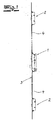
- Fig. 1
- ein Treibstangenschloss in vereinfachter Seitenansicht,
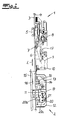
- Fig. 2
- einen vergrößerten Ausschnitt aus dem Gegenstand nach
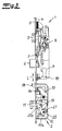
Fig. 1 in einer ersten Funktionsstellung und - Fig. 3
- den Gegenstand nach
Fig. 2 in einer zweiten Funktionsstellung, - Fig. 4
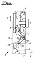
- einen vergrößerten Ausschnitt aus dem Gegenstand nach
Fig. 3 in einer anderen Ansicht und - Fig. 5
- den Gegenstand nach
Fig. 4 in einer anderen Funktionsstellung.
- Fig. 1
- an espagnolette in a simplified side view,
- Fig. 2
- an enlarged section of the object after
Fig. 1 in a first functional position and - Fig. 3
- the object after
Fig. 2 in a second functional position, - Fig. 4
- an enlarged section of the object after
Fig. 3 in a different view and - Fig. 5
- the object after
Fig. 4 in another functional position.
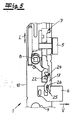
Die Zusatzverriegelungen 2 weisen jeweils einen Zusatzriegel 11 auf, welcher im Ausführungsbeispiel als Fallenriegel ausgebildet ist. Ferner weisen die Zusatzverriegelungen 2 jeweils eine in dem Zusatzschlossgehäuse 12 in Treibstangenlängsrichtung L verschiebbare Zusatzschlosskette 13 auf.The
Im Zuge des Entriegelns über das Zentralschloss 1 arbeitet die Zentralschlosskette 7 und die zugehörige Treibstange 4 auf die daran angeschlossene Zusatzschlosskette 13 der Zusatzverriegelung 2. Mittels der Zentralschlosskette wird der Zentralriegel 6 aus einer ausgeschlossenen Verriegelungsstellung in eine eingeschlossene Entriegelungsstellung überführt und umgekehrt. Mittels der Zusatzschlosskette 13 wird der Fallenriegel 11 der Zusatzverriegelung 2 aus einer ausgeschlossenen Verriegelungsstellung in eine eingeschlossene Entriegelungsstellung überführt und umgekehrt. Die Entriegelung erfolgt dabei üblicherweise durch Betätigung des Zentralschlosses 1 und folglich über die Treibstange 4, welche die Zusatzschlosskette 13 aus der Verriegelungsstellung in die Entriegelungsstellung überführt. Die Verriegelung erfolgt bei dem erfindungsgemäßen Treibstangenschloss selbsttätig bzw. automatisch, sobald die Tür bzw. der Türflügel in Schließstellung gelangt. Dazu ist vorgesehen, dass die Zusatzschlosskette 13 von einem Sperrelement 14 zunächst in der Entriegelungsstellung gehalten wird und dass in oder an einem der Zusatzverriegelung 2 zugeordneten türrahmenseitigen Schließleiste 15 ein Auslösemagnet 16 angeordnet ist. Dieser schließleistenseitige Auslösemagnet 16 arbeitet zum selbsttätigen Verriegeln bzw. für eine automatische Auslösung auf das Sperrelement 14, welcher dann die Zusatzschlosskette 13 freigibt, so dass der Zusatzriegel 11 in die Verriegelungsstellung überführt wird. Zugleich arbeitet die Zusatzschlosskette 13 jedoch über die Treibstange 4 auf die Zentralschlosskette 7, und zwar derart, dass im Zuge der Selbstverriegelung der Zusatzverriegelung 2 außerdem der Zentralriegel 6 des Zentralschlosses 1 aus der Entriegelungsstellung in die Verriegelungsstellung überführt wird. Im Rahmen der Erfindung ist folglich eine vollständige Selbstverriegelung vorgesehen, welche sowohl die Zusatzverriegelungen 2 als auch das Zentralschloss 1 betrifft. Dazu arbeitet die Zentralschlosskette 7 über einen schwenkbar in dem Zentralschlossgehäuse 10 gelagerten Verriegelungshebel 17 auf den Zentralriegel 6. Dieses ergibt sich insbesondere aus einer vergleichenden Betrachtung der
Eine vergleichende Betrachtung der
Nähert sich nun im Zuge des Schließens des Türflügels die Zusatzverriegelung 2 der Schließleiste 15, so löst der Magnet 16 die automatische Verriegelung aus, so dass der Sperrstift 14 nun die Schlosskette des Zusatzschlosses 2 freigibt, so dass der Zusatzriegel 13 über die Schwerkraft der Schlosskette 13 und andererseits über die Federkraft der Verriegelungsfeder 20 in die Verriegelungsstellung überführt wird, in welcher der Zusatzriegel 13 ausgeschlossen ist (vgl.
Die selbsttätige Verriegelung beschränkt sich jedoch nicht auf die Zusatzverriegelung 2, sondern sie betrifft auch das Zentralschloss 1, wie sich aus einer vergleichenden Betrachtung der
Der Kopplung zwischen Zusatzschlössern 2 und Zentralschloss 1 und der Kopplung der Zentralschlosskette 7 mit dem Zentralriegel 6 über den Verriegelungshebel 17, im Rahmen der Erfindung besondere Bedeutung zu. Die Selbstauslösung wird dabei vorzugsweise über einen Auslösemagneten realisiert. Die Erfindung umfasst jedoch auch Ausführungsformen, bei denen die Selbstauslösung mechanisch, zum Beispiel durch Auslösung über eine Riegelfalle im Zusatzschloss realisiert wird.The coupling between
Claims (7)
mit zumindest einem Zentralschloss (1) mit zumindest einem Zentralriegel (6) und einer verschiebbaren Zentralschlosskette (7),
und mit zumindest einer selbstverriegelnden Zusatzverrieglung (2) mit zumindest einem Zusatzriegel (11) und einer verschiebbaren Zusatzschlosskette (13),
wobei das Zentralschloss (1) über zumindest eine Treibstange (4) mit der Zusatzverriegelung (2) verbunden ist und der Zusatzriegel (11) mit dem Zentralschloss (1) über die Treibstange (4) und die Zusatzschlosskette (13) aus einer Verriegelungsstellung in eine Entriegelungsstellung überführbar ist und
wobei der Zusatzriegel (11) bei in Schließstellung gelangendem Türflügel durch Verschiebung der Zusatzschlosskette (13) selbsttätig in die Verriegelungsstellung überführt wird,
dadurch gekennzeichnet, dass die Zusatzschlosskette (13) der Zusatzverriegelung (2) über die Treibstange (4) auf die Zentralschlosskette (7) arbeitet und diese im Zuge der Selbstverriegelung der Zusatzverriegelung (2) den Zentralriegel (6) des Zentralschlosses (1) aus der Entriegelungsstellung in die Verriegelungsstellung überführt.Espagnolette with multiple locking,
with at least one central lock (1) with at least one central bolt (6) and a displaceable central lock chain (7),
and with at least one self-locking additional lock (2) with at least one additional bolt (11) and a displaceable additional lock chain (13),
wherein the central lock (1) via at least one drive rod (4) with the additional lock (2) is connected and the additional bolt (11) with the central lock (1) via the drive rod (4) and the auxiliary lock chain (13) from a locking position in a Unlocked position can be transferred and
wherein the auxiliary bolt (11) is automatically transferred into the locking position by moving the auxiliary lock chain (13) when the door leaf is reached in the closed position,
characterized in that the additional lock chain (13) of the additional lock (2) on the drive rod (4) on the central lock chain (7) works and this in the course of self-locking the additional lock (2) the central latch (6) of the central lock (1) from the Entriegelungsstellung transferred to the locking position.
Applications Claiming Priority (1)
| Application Number | Priority Date | Filing Date | Title |
|---|---|---|---|
| DE200920007674 DE202009007674U1 (en) | 2009-05-29 | 2009-05-29 | Espagnolette lock with multiple locking |
Publications (2)
| Publication Number | Publication Date |
|---|---|
| EP2256273A2 true EP2256273A2 (en) | 2010-12-01 |
| EP2256273A3 EP2256273A3 (en) | 2012-01-18 |
Family
ID=41011668
Family Applications (1)
| Application Number | Title | Priority Date | Filing Date |
|---|---|---|---|
| EP10003763A Withdrawn EP2256273A3 (en) | 2009-05-29 | 2010-04-08 | Drive rod lock with multiple locking points |
Country Status (2)
| Country | Link |
|---|---|
| EP (1) | EP2256273A3 (en) |
| DE (1) | DE202009007674U1 (en) |
Cited By (1)
| Publication number | Priority date | Publication date | Assignee | Title |
|---|---|---|---|---|
| GR20150100170A (en) * | 2015-04-20 | 2016-11-30 | Κλειθροποιϊα Domus A.E.B.E. | Geared multi-point lock |
Families Citing this family (3)
| Publication number | Priority date | Publication date | Assignee | Title |
|---|---|---|---|---|
| DE102009050305A1 (en) * | 2009-09-04 | 2011-03-17 | Hörmann Kg Brandis | Right / left usable front door elements |
| DE202009016137U1 (en) | 2009-11-30 | 2010-04-08 | Carl Fuhr Gmbh & Co. Kg | Espagnolette lock with panic function and multiple locking |
| DE202011103840U1 (en) | 2011-07-29 | 2011-11-30 | Carl Fuhr Gmbh & Co. Kg | Locking system with multiple locking for one door |
Family Cites Families (3)
| Publication number | Priority date | Publication date | Assignee | Title |
|---|---|---|---|---|
| DE3836693C2 (en) * | 1988-10-28 | 1996-01-25 | Fliether Karl Gmbh & Co | Espagnolette lock |
| DE10063784B4 (en) * | 2000-12-21 | 2007-11-15 | Wilka Schließtechnik GmbH | lock |
| ES2334299B1 (en) * | 2007-11-06 | 2010-08-09 | Talleres De Escoriaza S.A. | REVERSIBLE AUTOMATIC FORWARD FOR MULTIPOINT LOCKS. |
-
2009
- 2009-05-29 DE DE200920007674 patent/DE202009007674U1/en not_active Expired - Lifetime
-
2010
- 2010-04-08 EP EP10003763A patent/EP2256273A3/en not_active Withdrawn
Non-Patent Citations (1)
| Title |
|---|
| None |
Cited By (2)
| Publication number | Priority date | Publication date | Assignee | Title |
|---|---|---|---|---|
| GR20150100170A (en) * | 2015-04-20 | 2016-11-30 | Κλειθροποιϊα Domus A.E.B.E. | Geared multi-point lock |
| GR1009037B (en) * | 2015-04-20 | 2017-05-15 | Κλειθροποιϊα Domus A.E.B.E. | Geared multi-point lock |
Also Published As
| Publication number | Publication date |
|---|---|
| DE202009007674U1 (en) | 2009-08-27 |
| EP2256273A3 (en) | 2012-01-18 |
Similar Documents
| Publication | Publication Date | Title |
|---|---|---|
| DE102006059565B4 (en) | Locking system for doors, windows or the like, in particular espagnolette lock with panic function and multipoint locking | |
| EP2096241B1 (en) | Self-locking auxilliary lock | |
| EP2703585B2 (en) | Passive wing locking device with an actuation rod arrangement having a manipulation protection device | |
| DE2911681C2 (en) | Electric central locking device for motor vehicle doors | |
| EP0861960B1 (en) | Security lock | |
| EP3372757A1 (en) | Locking unit for a locking system of a door | |
| EP3299549A1 (en) | Stop door with outlet incline | |
| EP3147434B1 (en) | Drive device for a lock, in particular for a stand wing lock | |
| EP2256273A2 (en) | Drive rod lock with multiple locking points | |
| EP1739257B1 (en) | Lock | |
| DE202007016091U1 (en) | Espagnolette | |
| DE202009016137U1 (en) | Espagnolette lock with panic function and multiple locking | |
| DE102013000286A1 (en) | Door lock device for a door with at least one door leaf | |
| EP1990487A2 (en) | Door lock | |
| DE10151870B4 (en) | Device for actuating a closure of doors or flaps, in particular on vehicles | |
| DE1128323B (en) | Device for actuating and locking several locking devices on motor vehicles | |
| EP1344883B1 (en) | Locking device for a door | |
| EP0519905A1 (en) | Mortise lock | |
| WO2012119721A2 (en) | Furniture lock | |
| EP0990758A2 (en) | Additional lock for espagnolette | |
| EP0795665A2 (en) | Mortise lock | |
| DE102017208721A1 (en) | Counter box for a panic door lock | |
| EP2963215B1 (en) | Passive leaf lock | |
| EP0795663B1 (en) | Mortise lock | |
| DE102013012203B4 (en) | Electric door opener and a passive wing lock with such a door opener |
Legal Events
| Date | Code | Title | Description |
|---|---|---|---|
| PUAI | Public reference made under article 153(3) epc to a published international application that has entered the european phase |
Free format text: ORIGINAL CODE: 0009012 |
|
| AK | Designated contracting states |
Kind code of ref document: A2 Designated state(s): AT BE BG CH CY CZ DE DK EE ES FI FR GB GR HR HU IE IS IT LI LT LU LV MC MK MT NL NO PL PT RO SE SI SK SM TR |
|
| AX | Request for extension of the european patent |
Extension state: AL BA ME RS |
|
| PUAL | Search report despatched |
Free format text: ORIGINAL CODE: 0009013 |
|
| AK | Designated contracting states |
Kind code of ref document: A3 Designated state(s): AT BE BG CH CY CZ DE DK EE ES FI FR GB GR HR HU IE IS IT LI LT LU LV MC MK MT NL NO PL PT RO SE SI SK SM TR |
|
| AX | Request for extension of the european patent |
Extension state: AL BA ME RS |
|
| RIC1 | Information provided on ipc code assigned before grant |
Ipc: E05B 63/20 20060101ALI20111215BHEP Ipc: E05C 9/18 20060101ALI20111215BHEP Ipc: E05C 9/00 20060101AFI20111215BHEP |
|
| STAA | Information on the status of an ep patent application or granted ep patent |
Free format text: STATUS: THE APPLICATION IS DEEMED TO BE WITHDRAWN |
|
| 18D | Application deemed to be withdrawn |
Effective date: 20120719 |