EP2703583A2 - Passive wing locking device having a bolt push-back device with a spring-loaded bolt actuation pressure piece - Google Patents
Passive wing locking device having a bolt push-back device with a spring-loaded bolt actuation pressure piece Download PDFInfo
- Publication number
- EP2703583A2 EP2703583A2 EP13183043.2A EP13183043A EP2703583A2 EP 2703583 A2 EP2703583 A2 EP 2703583A2 EP 13183043 A EP13183043 A EP 13183043A EP 2703583 A2 EP2703583 A2 EP 2703583A2
- Authority
- EP
- European Patent Office
- Prior art keywords
- wing
- lock
- latch
- passive
- lock device
- Prior art date
- Legal status (The legal status is an assumption and is not a legal conclusion. Google has not performed a legal analysis and makes no representation as to the accuracy of the status listed.)
- Withdrawn
Links
Images


Classifications
-
- E—FIXED CONSTRUCTIONS
- E05—LOCKS; KEYS; WINDOW OR DOOR FITTINGS; SAFES
- E05C—BOLTS OR FASTENING DEVICES FOR WINGS, SPECIALLY FOR DOORS OR WINDOWS
- E05C9/00—Arrangements of simultaneously actuated bolts or other securing devices at well-separated positions on the same wing
- E05C9/04—Arrangements of simultaneously actuated bolts or other securing devices at well-separated positions on the same wing with two sliding bars moved in opposite directions when fastening or unfastening
- E05C9/041—Arrangements of simultaneously actuated bolts or other securing devices at well-separated positions on the same wing with two sliding bars moved in opposite directions when fastening or unfastening with rack and pinion mechanism
-
- E—FIXED CONSTRUCTIONS
- E05—LOCKS; KEYS; WINDOW OR DOOR FITTINGS; SAFES
- E05B—LOCKS; ACCESSORIES THEREFOR; HANDCUFFS
- E05B17/00—Accessories in connection with locks
- E05B17/20—Means independent of the locking mechanism for preventing unauthorised opening, e.g. for securing the bolt in the fastening position
- E05B17/2007—Securing, deadlocking or "dogging" the bolt in the fastening position
- E05B17/203—Securing, deadlocking or "dogging" the bolt in the fastening position not following the movement of the bolt
- E05B17/2038—Securing, deadlocking or "dogging" the bolt in the fastening position not following the movement of the bolt moving rectilinearly
-
- E—FIXED CONSTRUCTIONS
- E05—LOCKS; KEYS; WINDOW OR DOOR FITTINGS; SAFES
- E05B—LOCKS; ACCESSORIES THEREFOR; HANDCUFFS
- E05B17/00—Accessories in connection with locks
- E05B17/20—Means independent of the locking mechanism for preventing unauthorised opening, e.g. for securing the bolt in the fastening position
- E05B17/2007—Securing, deadlocking or "dogging" the bolt in the fastening position
- E05B17/203—Securing, deadlocking or "dogging" the bolt in the fastening position not following the movement of the bolt
- E05B17/2042—Securing, deadlocking or "dogging" the bolt in the fastening position not following the movement of the bolt moving otherwise than only rectilinearly and only pivotally or rotatively
-
- E—FIXED CONSTRUCTIONS
- E05—LOCKS; KEYS; WINDOW OR DOOR FITTINGS; SAFES
- E05B—LOCKS; ACCESSORIES THEREFOR; HANDCUFFS
- E05B63/00—Locks or fastenings with special structural characteristics
- E05B63/24—Arrangements in which the fastening members which engage one another are mounted respectively on the wing and the frame and are both movable, e.g. for release by moving either of them
- E05B63/248—Arrangements in which the fastening members which engage one another are mounted respectively on the wing and the frame and are both movable, e.g. for release by moving either of them the striker being movable for latching, and pushed back by a member on the wing for unlatching, or vice versa
-
- E—FIXED CONSTRUCTIONS
- E05—LOCKS; KEYS; WINDOW OR DOOR FITTINGS; SAFES
- E05B—LOCKS; ACCESSORIES THEREFOR; HANDCUFFS
- E05B65/00—Locks or fastenings for special use
- E05B65/10—Locks or fastenings for special use for panic or emergency doors
- E05B65/1086—Locks with panic function, e.g. allowing opening from the inside without a ley even when locked from the outside
-
- E—FIXED CONSTRUCTIONS
- E05—LOCKS; KEYS; WINDOW OR DOOR FITTINGS; SAFES
- E05C—BOLTS OR FASTENING DEVICES FOR WINGS, SPECIALLY FOR DOORS OR WINDOWS
- E05C7/00—Fastening devices specially adapted for two wings
- E05C7/04—Fastening devices specially adapted for two wings for wings which abut when closed
-
- E—FIXED CONSTRUCTIONS
- E05—LOCKS; KEYS; WINDOW OR DOOR FITTINGS; SAFES
- E05B—LOCKS; ACCESSORIES THEREFOR; HANDCUFFS
- E05B47/00—Operating or controlling locks or other fastening devices by electric or magnetic means
- E05B2047/0048—Circuits, feeding, monitoring
- E05B2047/0067—Monitoring
-
- E—FIXED CONSTRUCTIONS
- E05—LOCKS; KEYS; WINDOW OR DOOR FITTINGS; SAFES
- E05B—LOCKS; ACCESSORIES THEREFOR; HANDCUFFS
- E05B47/00—Operating or controlling locks or other fastening devices by electric or magnetic means
- E05B2047/0048—Circuits, feeding, monitoring
- E05B2047/0067—Monitoring
- E05B2047/0069—Monitoring bolt position
-
- E—FIXED CONSTRUCTIONS
- E05—LOCKS; KEYS; WINDOW OR DOOR FITTINGS; SAFES
- E05B—LOCKS; ACCESSORIES THEREFOR; HANDCUFFS
- E05B47/00—Operating or controlling locks or other fastening devices by electric or magnetic means
- E05B47/0001—Operating or controlling locks or other fastening devices by electric or magnetic means with electric actuators; Constructional features thereof
- E05B47/0012—Operating or controlling locks or other fastening devices by electric or magnetic means with electric actuators; Constructional features thereof with rotary electromotors
Definitions
- the passive wing lock device can be mounted in or on the passive wing. It has a lock mechanism and an actuating device for actuating the lock mechanism.
- the mechanical actuator is designed as a pusher or Panikdruckstange.
- the lock mechanism of the passive wing lock device has a latch lifting device and / or a latch lifting device. These are lifting devices for a trap or a latch of an active-wing-side mountable active-wing lock device. The purpose of these lifting devices is to excavate the latch and bolt of the associated active-wing lock device, which in its locking position protrude into the passive-wing lock device for opening the door, i. from the passive wing lock device push back into the active wing lock device and unlock before, if they are locked in their locking position.
- the lock mechanism with the gear of the lifting means is a relatively complex gearbox.
- the lock mechanism with the gear of the lifting means is a relatively complex gearbox.
- there may be changes and deviations of the movement path of the lifting devices so that a positionally accurate interaction with the trap to be excavated or the bolt to be lifted is no longer guaranteed.
- it can also come to movement disorders of the lifting devices, such as jerky movement to blocking by jamming.
- the latch or the latch is no longer completely back into the active leaf lock housing, so it can come to collide and block the door when opening.
- the lock mechanism of the passive wing lock device has a latch lifting device for retracting the bolt of the active wing lock device. Since the seaming air, ie the gap can vary between the cuff sides of the active wing and Pasiveriels at different door frame, the latch actuator is constructed in two pieces.
- the locking actuator has a base body on which an actuating pressure piece of the lifting device is mounted.
- the actuation pressure piece is mounted so as to be distanceable relative to the base body by screw connections in order to be able to ensure an exact positioning of the actuating pressure piece of the passive wing lock device with respect to the bolt of the active wing lock device by adjusting the screw connections in the manner of an adjustment.
- the invention has for its object to provide a passive wing lock device, which ensures a reliable lifting of latch and / or latch and also in double-leaf doors with a relatively large tolerance range and consequently gap between the wings can be used.
- the latch lifting device has a latch actuator, wherein the latch actuating element has a latch actuating pressure piece which is spring-loaded in the return direction of the bolt.
- the spring-loaded latch actuating pressure piece thus forms a resilient stop for cooperation with the bolt and / or with the active wing.
- the latch lifting device has a falling actuator, wherein the falling actuator has a falling actuating pressure piece which is spring-loaded in the return direction of the case.
- the spring-loaded falling actuation pressure piece thus forms a resilient stop for interaction with the trap and / or with the active wing.
- the latch actuating pressure piece and / or the falling actuating pressure piece has an inlet slope and / or an outlet slope.
- the inlet slope and / or the outlet slope of the latch actuating pressure piece is formed in the region of the free end as a prism-shaped end portion, and / or the inlet slope and / or the outlet slope of the falling actuating pressure piece in the region of the free end formed as a prism-shaped end portion.
- the prism-shaped end portion of the latch actuating pressure piece and / or falling actuating pressure piece is formed with only one bevel, which is formed as an inlet slope or as an outlet slope or is formed with two slopes, one of which as an inlet slope and the other than Outlet slope is formed.
- the bolt actuator is designed as a bolt actuating slide, which is guided in a fixedly mounted with the passive wing linear guide means which is directed horizontally in the mounted position of the passive wing lock device.
- the falling actuator is designed as a traction trigger, which in a is guided with the passive wing fixed mount linear guide device, which is directed horizontally in the mounted position of the passive wing lock device.
- the latch lifting device and / or the latch lifting device is coupled to the lock actuating device for driving and / or can be coupled.
- the latch lifting device has a sensor device to detect whether the trap of the active wing lock device engages or does not engage in a predetermined space of the passive wing lock device, wherein the sensor device is designed such that it depends on the result this detection emits electrical signals to an electrical signal processing device. Additionally or alternatively it can be provided that the latch lifting device has a sensor device to detect whether in a predetermined space of the passive lock device, the bolt of the active lock device engages or does not engage, wherein the sensor device (31t) is formed so that it depends on the result this detection emits electrical signals to an electrical signal processing device.
- the sensor device has an electrical signal-emitting sensor and a sensor interacting directly or indirectly with the sensor, which is movably mounted in the lock case of the passive-wing lock device and cooperates with the component to be detected in a tentative manner.
- the button is acted upon by a spring which urges the button in the scanning direction.
- the button in the lock case of the passive wing lock device is movable in the scanning direction limited, and indeed so far moved that it does not or only slightly protrudes beyond an end opening of the active wing facing end of the lock box.
- the pushbutton is designed as a pushbutton or feeler lever.
- the probe is designed as a push-button and the linear guide device of the bolt actuating slide is formed with a linear guide device of the probe and / or as a portion of the linear guide device. Additionally or alternatively, it may be provided that the probe is designed as a pushbutton and the linear guide device of the falling actuating slide is formed with a linear guide device of the feeler and / or as a portion of the linear guide device.
- the lock mechanism has a gear slide, which is connected to the latch lifting device and / or the latch bolt lifting device.
- the present invention is further directed to a lock device for a door, a window or the like, with a stationary mountable frame mounted on or in the frame, at least one active wing - hereinafter referred to as active wing - and at least one passive wing - hereinafter referred to as passive wing.
- It includes the Locking device a passive wing lock device that can be mounted in or on the passive wing, and an active wing lock device that can be mounted in or on the active wing.
- the active wing lock device has a lock mechanism with a latch and / or a bolt, and that the passive wing lock device is designed according to one of the preceding claims.
- the passive wing lock device is designed as a mortise lock and preferably also the active wing lock device designed as a mortise lock.
- the present invention is further directed to a door or window, with a fixed mountable frame mounted on or in the frame, at least one active wing - hereinafter referred to as active wing - and at least one passive wing - hereinafter referred to as passive wing, with a Locking device comprising an active wing lock device and a passive wing lock device, wherein the active wing lock device is mounted in or on the active wing and the passive wing lock device is mounted on the passive wing.
- the active wing lock device has a latch and / or a bolt
- the passive wing lock device is designed according to one of claims 1 to 13.
- a lock box-fixed linear guide device can be arranged in the lock case of the passive lock device, in which the actuating element is guided during extension and retraction.
- the actuating element can be designed as a slide, on supported by a spring, the actuating pressure piece, which preferably comes directly to the case or the latch in abutment layer stores.
- the actuating pressure piece can also be guided in the linear guide. Alternatively, however, alone the actuating pressure piece can be performed in the linear guide.
- the spring loading can be formed by a correspondingly resilient or elastic transmission device, with which the lifting device in question is connected to the rest of the lock transmission.
- This transmission device can be formed as a lever mechanism, wherein at least one of the levers can be resiliently mounted or elastically resilient.
- a complementary in conjunction with the resilient mounting measure may advantageously be that the pressure piece of the bolt actuating element has an inlet slope and / or an outlet slope.
- the actuating pressure piece of the falling actuator may have an inlet slope and / or an outlet slope in particular embodiments.
- the inlet slope and / or the outlet slope of the pressure piece is formed in the region of the free end as a prism-shaped end portion. This applies to the actuating pressure piece of the latch actuator and the actuating pressure piece of the falling actuator.
- the inlet and outlet slopes, in particular in connection with the spring-loaded bearing, ensure that no mutual collision and blocking of the wings occurs when the door is opened and closed.
- the prism-shaped end portion of the latch actuating pressure piece and / or the falling actuating pressure piece is formed with only one bevel, which is formed as an inlet slope or as an outlet slope or is formed with two slopes, one of which is designed as inlet slope and the other as outlet slope.
- the falling actuator is designed as a traction control slide, which is guided in a fixedly mounted with the passive wing linear guide device which is directed horizontally in the mounted position of the passive wing lock device, and / or that the locking actuator as Latch actuating slide is formed, which is guided in a fixedly mounted with the passive wing linear guide means which is directed horizontally in the mounted position of the passive wing lock device.
- the latch lifting device and / or the latch lifting device is coupled to the drive and / or coupled to the manual lock operating device or the motorized lock operating device.
- the lock mechanism has a gear slide, which is connected to the latch lifting device and / or the latch bolt lifting device.
- the gear slide is guided in a solid with the passive wing linear guide device.
- the gear slide is coupled or detachable with the manual lock operating device and / or the motor-operated lock operating device.
- the latch lifting device has a sensor device for detecting whether the passive wing lock device engages or does not engage the trap of the active-leaf lock device in a predetermined space, the sensor device depending on the result of this detection electrical signals emits to an electrical signal processing device; and / or b) that the latch lifting device has a sensor device in order to detect whether the latch of the active-leaf lock device engages or does not engage in a predetermined space of the passive-wing lock device, wherein the sensor device emits electrical signals to an electrical signal-processing device as a function of the result of this detection ,
- the sensor device an advantageous control and monitoring of the lifting devices of bolt and trap is possible. Furthermore, monitoring of the closing and locking position of the door is possible with the sensor device.
- the passive lock devices provide that the gear slide with an upper locking bar connecting device for connecting a guided in and / or on the passive wing upper locking bar and / or with a lower locking bars Connection device for connecting a guided in and / or on the passive wing lower locking bar coupled and / or can be coupled.
- the passive wing lock device has a lock case which can be mounted in and / or on the passive wing and in which the lock mechanism is mounted.
- the lock operating device is designed as a manual and / or as a motor preferably electromotive actuator.
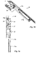
- passive wing lock devices 30 which are each mounted in a passive wing 110 of a two-leaf door. These passive wing lock devices 30 are each intended to cooperate with an active wing lock device, which are to be mounted according to assigned in an active wing of the two-leaf door.
- FIGS. 1a to 1c An embodiment of an active wing lock device 1 mounted in an active wing 10 of a two-leaf door is in the FIGS. 1a to 1c shown in its interaction with an associated passive wing lock device which is mounted in the passive wing 110.
- the passive wing lock device 30 of the FIGS. 1 a. 1 b and 1 c has a lock mechanism which is mounted in a lock case 30a.
- the lock case 30a is mounted in a receiving pocket inserted into the passive wing 110.
- the lock mechanism comprises a lock gear with a gear slide 36 which is coupled in terms of gear with a lock nut 37 rotatably mounted in the lock case 30a.
- the gear slide 36 is vertically guided in the lock case up and down.
- the passive wing lock device 30 includes upper and lower latch bars 380o, 380u and lift-out devices 31 and 32 for lifting the latch 11 and latch 12 of an associated active-wing lock device engaging the passive-wing lock device in the locking position.
- the lock transmission with the gear slide 36 serves to drive the upper locking bar 380o and the lower locking bar 380u and to drive the lifting devices 31 and 32.
- the structure and function of the lifting devices 31 and 32 will be explained in more detail below in conjunction with the figures.
- the upper locking bar 380o is coupled to an upper locking bar connection device 38o mounted in the upper section of the lock case 30a.
- This upper connection device 38o is connected to the transmission slide 36 via a Reverse gear 36g connected.
- the reverse gear 36g is a gear transmission.
- the upper end of the gear slider 36 is formed as a rack and the upper locking bars connecting piece 380 also has a rack.
- a gear mechanism is rotatably mounted in a lock housing fixed pivot bearing. The gear device meshes with the linearly guided in the lock housing racks of gear slide 36 and locking bars connection device 38o.
- the two racks are facing each other in parallel aligned with intermediate gear mechanism, so that the two racks move in opposite directions in the vertical direction. This implies that upon a displacement of the gear slide 36 upwards, the upper locking bar connection device 38o is moved down and the locking bar connecting device 38o is moved upwards by means of a displacement of the gear slide 36.
- the lower latch bar 380u is coupled to a lower latch bar terminal 38u mounted in the lower portion of the latch box 30a.
- This lower locking bar connection device 38u is coupled in the same direction with the transmission slide 36, so that upon displacement of the transmission slide 36 upwards the lower locking bar connection device mit compiler and with a displacement of the transmission slide 36 down the locking bar connection device 38u down mitmaschine.
- the locking bars 380o and 380u thus driven are mounted vertically directed on the passive wing 110 and indeed linearly displaceable, in each case in a corresponding vertical linear guide, preferably concealed in the frame the passive wing displaceable.
- the locking bars 380o and 380u are each movable in opposite directions vertically up and down by their motion-resistant coupling to their associated connection device 38o or 38u via the actuation of the gear slide 36.
- the upper end of the upper latch bar 380o cooperates with a latch receiving recess formed in the upper rail of the stationary frame of the door.
- the lower end of the lower latch bar 380u cooperates with a latch receiving recess formed in the bottom.
- the free upper end of the locking bar engages in the upper latch receiving recess.
- the free lower end of the latch bar engages the lower latch receiving recess.
- the latch lifting device 31 serves to cooperate with the latch 11 of the active wing lock device 1.
- the interaction consists in that the latch lifting device 31 returns the latch 11 to the lock case 1a of the active wing lock device 1, in which the latch lifting device 31 locks the latch 11 pressurized while pushing back until the latch 11 is completely inserted into the lock case 1 a of the active wing lock device 1.
- the trap lifting device 31 has a latching actuating slide 31 a, which is driven by the gear slide 36 via a lever device 31 h.
- the lever device 31 When the transmission slide 36 is pushed upwards, the lever device 31 is swung out so that the trailing edge of the actuating slide 31 a extends.
- the lever means 31 is pivoted h, so that the trailing control slide 31a is retracted again.
- the latch lifting device 32 is used for unlocking and retracting the bolt 22 of the active lock device 1.
- the latch lifting device 32 has in a corresponding manner a latch actuating slide 32a, which is drive-connected via a lever gear 32h with the gear slider 36.
- a latch actuating slide 32a which is drive-connected via a lever gear 32h with the gear slider 36.
- the latch 22 After the latch 22 is unlocked, it is moved back into the lock case 1 a of the active wing lock device by further pressurization, which acts on the front side of the latch 22.
- the lever mechanism 32h of the latch actuating slide 32a When pivoting back the lever mechanism 32h of the latch actuating slide 32a is then retracted. This happens because the gear slide 36 is moved in the vertical direction down.
- a linear guide means 32b of the latch actuating slide 32a intended in the lock case 30a.
- the linear guide device 32b is directed horizontally in the lock case 30 so that the lock operating slide 32a can be moved in and out horizontally.
- a correspondingly linear guide device can also be designed for the trailing control slide 31 a of the lever 31 in the lock case 30 a, as z. Tie Figures 6a and 6b is shown for the embodiment shown there.
- the latch lifting device 32 is also referred to as a latch unlocking and or retracting. It can be designed both for unlocking and for retracting the bolt, as in the in the FIGS. 1a . 1b and 1c illustrated case.
- the latch lifting device 32 may be formed in other embodiments but also only as a latch retracting device.
- a separate device or at least a separate unlocking mechanism can be provided, which can be optionally also driven as a time delay by the gear slide 36 via the same lever means 32h or another separate lever means or via another gear. This is especially true if the latch 22 is not provided with a release pin mounted in the latch, ie if another trigger element, for. B. separately from the latch 22, z. B.
- the latch lifting device 32 may also be designed as unlocking device in modified embodiments, ie the latch actuating slide 32a can then switch off the locking by appropriate pressurization of the triggering mechanism.
- the retraction of the bolt can optionally be replaced by another mechanism z. B. done with a corresponding spring action of the bolt.
- the spring device in question can on the lock box 1a the active wing lock device but also be supported on the passive wing lap box 1 a.
- the latch lifting device 31 is also referred to as a latch unlocking and / or retracting device. She can, as in the FIGS. 1a . 1b and 1c illustrated case, be designed only as a fall-back device for a case 11, which is designed as a spring-loaded in the extension direction conventional latch, which is not self-locking.
- the spring-loaded latch 11 has a prism-shaped end portion having an inlet slope, so that when pulling the active wing 10, that is, when the active wing 10 is pulled or pressed into the closed position, the latch 11 abuts the inlet slope on the frame of the passive wing 110 and against the spring loading the latch 11 is retracted.
- the slope facing away from the inlet slope of the latch 11 is not designed as a slope, but as a parallel to the wing plane blocking surface, so that an active operation of the latch 11 is required for opening the door or in a modified embodiment in which the latch 11 with a Door opener trap cooperates, the door latch is actuated.
- an electric door opener can be arranged in the passive wing lock device. The latch 11 can then interact with the door latch case and the door can be released from the closed position by electrical actuation of the latch opener.
- the latch 11 may also be designed as a self-locking latch - as a so-called latch bolt.
- the latch bolt can occupy three positions, namely a first retracted into the lock case 1a position a second extended from the lock case position comparable to the extended position in conventional lock traps and a third position in which the latch bolt is far extended and locked at the same time and / or at least locked acts. In this third position, the latch bolt is extended approximately twice as far as a conventional latch in its extended position. In addition, in this widely extended third position of the latch bolt, as already mentioned, locked. It should be noted on the FIGS. 7a and 7b showing an embodiment in which the trap 11 is formed as such a latch bolt.
- the trap lifting device 31 is designed as a latch unlocking and retracting means, ie the traps actuating slide 31 a serves to unlock the latch bolt 11 in a first phase of the lifting operation and drive back the latch bolt in the course of the lifting operation.
- Unlocking takes place in that the release pin 11 a, which is slidably mounted in the latch bolt, is first retracted by the latching actuating slide 31 a, ie, first in the locking position of the latch bolt 11 protruding free end of the trigger pin 11 a through the latch actuating slide 31st a retracted.
- By retracting the unlocking of the bolt 11 takes place, so that the latch bolt is moved back under further pressurization by the trailing control slide 31 a.
- latch lifting device 31 is designed only as unlocking or only as a retracting device.
- the return or unlocking can be done via a separate device. The same applies as described above for the bolt lifting device 32 in connection with the unlocking or retraction of the bolt.
- FIGS. 2a and 2 B is one opposite the FIGS. 1a . 1b and 1c modified embodiment shown in which the trap lever 39 is modified.
- the trailing actuating slide 31 a has an actuating plate which is hinged to a driven-side actuating lever of the lever mechanism 31 b.
- the actuating lever has a fixed in the lock case 30 a pivot bearing and is comparable to the FIGS. 1a . 1b and 1c actuated by the transmission slide 36, but structurally modified by a mounted on the operating lever pressure pin is guided in a slot in the transmission slide 36.
- FIGS. 1a . 1b and 1c acts a control edge of the Gear slide 36 together with the pressure pin of the actuating lever, wherein the control edge is formed in the edge contour of the spool 36.
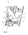
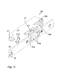
- FIGS. 3a and 3b is one opposite the FIGS. 1a . 1b and 1c modified embodiment shown in which the latch lifting device 32 is modified.
- the bolt actuating slide 32a has a plate-shaped base body, which is guided horizontally in the edge in the fixed in the lock case 30a linear guide device 32b.
- the operating lever of the operating gear 32h is similar to that in Figs FIGS. 2a and 2 B guided in a slot in the gear slider 36 with the pressure pin mounted on the gear lever.
- the latch lifting device 32 is structurally similar as in the embodiment of FIGS. 3a and 3b ,
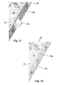
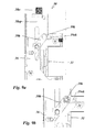
- the trap lifting device 31 is in the embodiment of Figures 6a and 6b as well as the embodiment of FIGS. 7a to 7d across from the embodiments of the FIGS. 1a . 1b and 1c and the FIGS. 2a and 2 B modified in such a way that the trap lifting device 31 has a sensor device 32 t, with which it is detected whether the case 22 in the lock case 30 a of the passive wing lock device is retracted or extended or is just retracted or extended.
- the trap lifting device 31 has as in the Figures 6a and 6b and even better in the FIGS. 7a to 7d can be seen a trap actuating slide 31 a, which is guided horizontally with its plate-shaped base body in the fixed in the lock case linear guide device 31 b.
- a sensor plate 31 tp is displaceably guided in the linear guide device 31 b.
- the sensor plate 31 tp has at its front end edge two contact plates which come into contact with the case 11.
- the sensor plate 31 tp is acted upon via a spring, in the illustrated case a leg spring, to the outside.
- the spring is dimensioned so that it is suppressed when retracting the case 11 and the case takes the sensor plate 31 tp in abutment with the contact plates.
- the sensor plate 31 tp has at its in the Figures 6a and 6b lower edge region on a lateral actuating edge, which interacts with the oblique-angled actuating edge of a plate-shaped detection element 31 te, which is movably mounted in a fixed housing in the lock case.
- the detection element 31 te has an extension which engages in a arranged in the lock housing 1a light sensor 31 s when the sensor plate 31tp enters the lock housing 30a.
- the sensor device 31t Another possible function of the sensor device 31t is that e.g. can be monitored via a central office, whether the two-leaf door is closed and locked. As regards the locking monitoring, this applies to embodiments in which the case is designed as a latch bolt and for embodiments in which a corresponding sensor device is additionally or alternatively provided in the region of the bolt lifting device 32.
- FIG. 12 shows an embodiment of the passive wing lock device with a sensor device 31 s, with respect to the sensor device 31 t of the embodiment of FIGS. 7a to 7f is modified.
- the sensor device 31 s of FIG. 12 serves the sensor device 31 s of FIG. 12 for detecting whether the latch 22 is retracted or extended in the lock box 30a of the passive wing lock mechanism, or is being retracted or retracted.
- the sensor device 31 s is composed of a light sensor 31 se and a sensor stylus 31 st together.
- the light sensor 31 se is an optical sensor. He has a U-shaped receptacle into which engages the free end of the sensor button 31 st.
- FIGS. 12 shows an embodiment of the passive wing lock device with a sensor device 31 s, with respect to the sensor device 31 t of the embodiment of FIGS. 7a to 7f is modified.
- the sensor device 31 s is composed of a light sensor 31 se and a sensor stylus 31 st together.
- FIG. 12 the sensor button not as a slide, but designed as a two-armed lever.
- the sensor button 31 st in FIG. 12 acts directly with the light sensor 31 se.
- FIGS. 7a to 7f is between the light sensor 31 s and the button 31 tp and a wedge-shaped transmission member 31 te provided.
- the sensor button 31 st of the sensor device in FIG. 12 is designed as a sensing lever which pivotable about a lock box fixed axis 31 sta Lock case is stored.
- the sensing lever 31 st is designed as a two-armed lever.
- the first lever arm 31 stt serves to key the latch 11 of the active wing lock device.
- the second lever arm 31 sts has a hook-like extension which projects into the U-shaped receptacle of the light sensor 31 s.
- the first lever arm 31 stt of the sensing lever 31 st projects into the predetermined space of the passive wing lock, which is provided for receiving the latch 11 of the active wing lock.
- FIG. 12 spring not shown, which acts on the sensing lever 31 in the direction of the outward direction.
- the sensor device operates as follows: In the closed position of the door, the latch 11 of the active lock device moves spring-loaded into the space provided for receiving the latch 11 of the passive wing lock device. In this case, the case 11 comes with the first lever 31 stt of the sensing lever 31 st in contact, so that the sensing lever 31 st is pivoted by the entering into the passive wing lock device case 11 about its axis of rotation 31 sta around.
- the hook-like extension of the feeler lever 31 st which projects into the light sensor 31 s when the door is open, then, when the trap 11 has reached its closed position, leave the U-shaped receptacle of the light sensor 31 se.
- the light sensor 31 se outputs depending on its operation or non-operation corresponding electrical signals, which are processed by an electrical signal processing system.
- the interaction of the sensing lever 31 st and the light sensor 32se may also be provided so that the sensing lever 31 st in the light sensor 31 se engages when the case 11 is retracted into the receiving space of the passive lock box. With the sash open The hook-like extension of the feeler lever 31 then stalls outside the recording of the light sensor 31. Also in this modified embodiment, the light sensor 31 se depending on its operation or non-operation corresponding electrical signals from which are processed by an electrical signal processing system.
- FIG. 13 shows an embodiment of the passive wing lock device with two further sensor devices 32s and 37s, one of which is associated with the latch 22 and the other of the lock nut 37.
- the sensor device 32t is used to detect whether the latch 22 is retracted or extended in the lock case 30a of the passive-wing lock device or is being retracted or extended.
- This sensor device 32t has an analog construction to the sensor device 31t FIG. 12 which detects the position of the trap.
- the sensor device consists of a light sensor 31 se and a sensor button 31 st.
- the sensor button 31 st is also designed as a two-armed lever which is pivotally mounted in the lock case about an axis 31 sta.
- the sensor button 31 st has a first lever arm 31 stt, which is used for sensing the latch 22, and a second lever arm 31 sts, which cooperates with the light sensor 31 se.
- the sensor device 37s serves to detect an actuation of the lock nut 37.
- a light sensor 37se is provided.
- the lock nut 37 has a radially projecting arm 37fs which is provided with an extension formed as an angled edge. In the rest position of the passive wing lock device, the extension 37fs projects into the U-shaped receiving area of the light sensor 37se. If the actuation handle is actuated by a user on the passive wing lock, the locknut becomes 37 shot. In this case, the edge-like extension 37fs of the lock nut 37 then leaves the receiving area of the electric light sensor 37se. The light sensor 37se then outputs a corresponding electrical signal that can be processed by an electrical signal processing system. By means of the sensor device 37s, it can be detected whether the passive wing lock has been opened by the manual actuation of a handle or push rod arranged on the passive wing.
- a sensor device 36s which serves to detect a movement of the transmission slide 36.
- a light sensor 36se is provided.
- the gear slider 36 has a projecting projection 37fs.
- the extension 37f is outside the U-shaped receiving area of the light sensor 37se. If the passive wing lock is actuated by the actuating handle by a user or by the motorized actuating device, the gear slide 36 is thereby pushed upwards.
- the extension 36fs of the gear slider 36 enters the receiving area of the electric light sensor 36se.
- the light sensor 36se then outputs a corresponding electrical signal that can be processed by an electrical signal processing system.
- the sensor device 37t it can be detected whether the passive wing lock has been opened by the manual actuation of a handle or push rod arranged on the passive wing.
- the sensors 31 se, 32se, 36se and 37se are mounted on a common plate mounted in the lock box.
- an electronic device for evaluating and / or processing the data of the sensors is provided.
- This electronic device can be in one be arranged separate housing. This separate housing may preferably be arranged adjacent to the lock case coupled.
- Using the information from the sensors 31 s and 32 s can be monitored, for example, in a public building by a central, whether a two-leaf door is open or is in the closed position or locked. Furthermore, it can be tracked by a monitoring center, whether a door has been unlocked by operating the nut or by activating the motorized actuator.
- the position of the lock nut remains unchanged and the signal of the sensor 37s remains unchanged, while an unlocking by operating the handle rotation of the lock nut 37 results and is detected by the nut associated sensor 37s.
- the sensors can also be used to control the motorized actuator when unlocking the lock device. By means of the sensors 31 se and 32se, it can be detected during unlocking whether the latch 11 or the bolt 22 no longer protrude into the associated receptacles of the passive wing lock, whereupon the motorized actuating device can be deactivated.
- the operation of the passive wing lock device 30 can be done via a manual control device, not shown in the figures.
- the manual actuating device can be designed as a rotary handle which can be inserted into the lock nut 37, wherein the lock nut 37 forms a part of the lock transmission.
- the rotary handle can be designed as a conventional pusher or as a push rod, a so-called panic push rod. Both the pusher and the push rod may have a corresponding rotary connection, which is rotatably inserted for coupling with the lock gear in the lock nut 37.
- the lock nut 37 By operating the actuator, the lock nut 37 is rotated and thereby actuates the lock gear. With the operation of the lock transmission of the transmission slide is moved. With the operation of the lock transmission, the locking bars 38e, 38u are displaced vertically in opposite directions depending on the direction of rotation of the actuation. In addition, the latch lifting device 31 and the latch lifting device 32 are actuated simultaneously or with a delay in the operation of the lock transmission.
- the lock transmission is designed so that an actuation of the lock nut 37 in one direction, the upper locking bars 38o up device and the lower locking bar connection device 38u shifts downward, and consequently the respective locking bars 380o and 380u are each extended so moved into their locking position.
- the lifting means 31, 32 for lifting the latch 11 and the bolt 12 are thereby actuated via the lock gear so that the trailing control slide 31 a and the bolt actuating slide 32 a in the Lock housing 30a of the passive lock device 30 are retracted.
- a motor actuator which in contrast has a linear output.
- the linear drive can be coupled directly to the transmission slide 36.
- the operation of the lock gear by the linear drive of the motorized actuator then acts in the same manner as when the lock gear is operated via rotation of the lock nut 37, as described above.
- FIGS. 5a and 5b show the passive wing lock device 30 with a arranged at the lower end of the lock case 30a such motor actuator 37m.
- FIGS. 5c and 5d show the coupled to the transmission slide coupling slide 37k, without the motor actuator 37m is coupled.
- the embodiment with the motorized actuator may be optional.
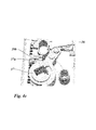
- FIG. 4b shows the blocking member 39b in the blocking position in a tampering attempt.
- the gear slider 36 has been made by manipulation Pressurizing the locking bars relative to the position in FIG. 4a moved a little way up and is held against further upward displacement by the blocking member 39b.
- Figure 4c shows the blocking member 39 b in the release position in which it is out of engagement of the gear slide 36.
- the blocking member 39b is displaced in this release position by the operation of the lock nut 37 in that by rotation of the lock nut 37 in the figure in the figure in the counterclockwise direction of the cam follower 37 fixed driver 37a cooperating with the blocking member 39b and the blocking member 39b in the representation in the Figure 4c moved to the left.
- This first embodiment of the anti-tamper device in the FIGS. 4a to 4c thus acts on the transmission slide 36 and thus on both locking bars; However, it requires an actuator on the lock nut 37.
- a second embodiment of a tamper protection device is in the FIGS. 9a and 9b shown. This manipulation protection device requires no operation of the lock transmission via the lock nut 37, but the operation of the lock gear can also be via a linear output of the gear slide, for example via the motorized actuator 37m of FIGS. 5a and 5b respectively.
- This embodiment of the anti-tamper means sees in the embodiment of FIGS. 9a and 9b a link device 39k, which is formed between the upper locking bar connecting device 38o and the gear slider 36.
- the gate device 39k has a cam slot 39ok, which is formed with the plate-shaped main body of the upper locking bar connecting device 38o.
- the link mechanism 39k further comprises a lever 39h, which in a castle box fixed pivot bearing is mounted and has a guide pin at one end, which engages in the slot slot 39ok and at its other end has a guide pin which engages in a slot formed in the gear slide 36.
- the gate device 39k described above thus forms in the embodiment described above FIGS. 9a and 9b a manipulation protection device for the upper locking bar 380o.
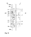
- a tamper protection device provided, as in the Figures 10a and 10b is shown.
- This manipulation protection device has a blocking lever 39p, which is mounted in a lock box-fixed pivot bearing. He is spring-loaded and / or gravitational in the in FIG. 10a with its free end to the left-facing position.
- a blocking pin 39s which is resistant to movement with the gear slide 36, engages in the hook-shaped recess of the blocking lever 39p in this position.
- FIG. 10c shows the situation in case of a manipulation attempt.
- the plate-shaped base body of the lower locking bar connection device 38u is driven by the upwardly acting pressurization of the locking bar 380u in the oblong holes driven up and comes into abutment against the lower bottom of the blocking lever 39p.
- a displacement of the lower locking bar 380u is counteracted in a manipulation attempt and the lower locking bar 380u is blocked in the extended position.
- the vertical movement of the lower bar connecting device 38a is thus not transmitted to the transmission slide 36.
- FIG. 11 shows an eleventh embodiment of the passive wing lock device with a tamper protection device for the lower locking bar 380u, wherein the anti-tamper according to FIG. 11 opposite the anti-tamper device according to FIGS. 10a to 10c is modified.
- the manipulation protection device has a blocking lever 39p, which is mounted in a lock box-fixed pivot bearing.
- the blocking lever has a blocking stop 39b which, in the blocking position, cooperates with the lower locking bar connection device 38u, as in FIG FIG. 11 is shown.
- the blocking stopper 39b is formed as an abutment step of the side edge of the blocking lever 39p.
- the manipulation attempt is in FIG. 11 shown.
- FIG. 11 shows the tamper protection in a tampering attempt.
- the manipulation protection is that when pressure is applied to the lower locking bars connecting device 38u, the lower locking bar connecting device 38u comes into abutment against the blocking stop 39b of the blocking lever 39p and is thus blocked against further displacement in the vertical upward direction. As a result, no vertical movement is transmitted to the gear slider 36 through the lower latch bars 38u.
- the blocking lever 39p is provided with a cam slot into which a cam pin 36k of the gear slider 36 engages. If, in the event of a proper unlocking by operation of the nut 37 or the motor actuator 37m of the transmission slide 36 is displaced upwards for unlocking, the gear shifter fixed pin 36k moves vertically upwards and runs in the sliding slot 39k of the blocking lever, whereby the blocking lever 39p is pivoted in the illustrated case counterclockwise.
- the blocking lever 39p projects in the pivoted then no longer in a blocking manner in the Movement range of the lower locking bar connecting device 38u into it. Simultaneously with the pivoting of the blocking lever 39p, a lever 38h is pivoted.
- the lever 38h is pivotally mounted in the lock case 38a about a lock case fixed axis 38a and cooperates with a foot side arranged on the transmission slide 36 actuation stop.
- the lever 38 When pushing up the gear slide 36, the lever 38 is pivoted clockwise in the illustrated case.
- the lever 38h is formed as an operating lever of the lower locking bar connecting device 38u. He interacts with its free end with a corresponding stop on the lower locking bar connection device 38u together.
- the lower locking bar connecting device 38u is thus moved in the same direction with the transmission slide 36 and retracted the lower locking bar in the lock case.
Abstract
Description
Die Erfindung betrifft eine Passivflügel Schlosseinrichtung für eine Tür, ein Fenster oder dergleichen. Die Tür weist einen ortsfest montierbaren Rahmen mit in dem Rahmen gelagerten mindestens einem aktiven Flügel und mindestens einem passiven Flügel auf. Es handelt sich also um eine zweiflügelige Tür. Der aktive Flügel wird im folgenden als Aktivflügel bezeichnet. Der passive Flügel wird im folgenden als Passivflügel bezeichnet.The invention relates to a passive wing lock device for a door, a window or the like. The door has a fixed mountable frame with at least one active wing and at least one passive wing mounted in the frame. It is therefore a double-leaf door. The active wing is referred to below as active wing. The passive wing is referred to below as the passive wing.
Die Passivflügel Schlosseinrichtung ist in oder auf dem Passivflügel montierbar. Sie weist eine Schlossmechanik und eine Betätigungseinrichtung zur Betätigung der Schlossmechanik auf. Es sind Passivflügel Schlosseinrichtungen mit einer mechanischen Betätigungseinrichtung bekannt, wobei die mechanische Betätigungseinrichtung als Drücker oder Panikdruckstange ausgebildet ist.The passive wing lock device can be mounted in or on the passive wing. It has a lock mechanism and an actuating device for actuating the lock mechanism. There are passive wing lock devices with a mechanical actuator known, the mechanical actuator is designed as a pusher or Panikdruckstange.
Die Schlossmechanik der Passivflügel Schlosseinrichtung weist eine Fallen Aushebeeinrichtung und/oder eine Riegel Aushebeeinrichtung auf. Es handelt sich dabei um Aushebeeinrichtungen für eine Falle bzw. einen Riegel einer aktivflügelseitig montierbaren Aktivflügel Schlosseinrichtung. Sinn und Zweck dieser Aushebeeinrichtungen ist es, die Falle und den Riegel der zugeordneten Aktivflügel Schlosseinrichtung, die in ihrer Verriegelungsposition in die Passivflügel Schlosseinrichtung hineinragen zum Öffnen der Tür auszuheben, d.h. aus der Passivflügel Schlosseinrichtung zurückzuschieben in die Aktivflügel Schlosseinrichtung und zuvor zu entriegeln, falls sie in ihrer Verriegelungsposition verriegelt sind.The lock mechanism of the passive wing lock device has a latch lifting device and / or a latch lifting device. These are lifting devices for a trap or a latch of an active-wing-side mountable active-wing lock device. The purpose of these lifting devices is to excavate the latch and bolt of the associated active-wing lock device, which in its locking position protrude into the passive-wing lock device for opening the door, i. from the passive wing lock device push back into the active wing lock device and unlock before, if they are locked in their locking position.
Bei den bekannten derartigen Schlossvorrichtungen ist nachteilig, dass die Schlossmechanik mit dem Getriebe der Aushebeeinrichtungen ein relativ komplexes Getriebe darstellt. Insbesondere bei längeren Lebenszyklen kann es zu Veränderungen und Abweichungen der Bewegungsbahn der Aushebeeinrichtungen kommen, sodass ein positionsgenaues Zusammenwirken mit der auszuhebenden Falle bzw. dem auszuhebenden Riegel nicht mehr gewährleistet ist. Es kann in diesem Zusammenhang auch zu Bewegungsstörungen der Aushebeeinrichtungen, etwa wie ruckartige Bewegung bis hin zum Blockieren durch Verklemmen kommen. Es kann auch dazu kommen, dass die Falle bzw. der Riegel nicht mehr vollständig in das Aktivflügel Schlossgehäuse zurückverfahren wird, sodass es zur Kollision und zum Blockieren der Türflügel beim Öffnen kommen kann.In the known such lock devices is disadvantageous that the lock mechanism with the gear of the lifting means is a relatively complex gearbox. Especially with longer life cycles, there may be changes and deviations of the movement path of the lifting devices, so that a positionally accurate interaction with the trap to be excavated or the bolt to be lifted is no longer guaranteed. In this context, it can also come to movement disorders of the lifting devices, such as jerky movement to blocking by jamming. It may also happen that the latch or the latch is no longer completely back into the active leaf lock housing, so it can come to collide and block the door when opening.
Aus der
Der Erfindung liegt die Aufgabe zugrunde, eine Passivflügel Schlosseinrichtung zu schaffen, die ein zuverlässiges Ausheben von Falle und/oder Riegel gewährleistet und auch in zweiflügeligen Türen mit relativ großem Toleranzbereich und demzufolge Spalt zwischen den Flügeln einsetzbar ist.The invention has for its object to provide a passive wing lock device, which ensures a reliable lifting of latch and / or latch and also in double-leaf doors with a relatively large tolerance range and consequently gap between the wings can be used.
Die Erfindung löst die Aufgabe mit dem Gegenstand des Patentanspruchs 1.The invention achieves the object with the subject matter of patent claim 1.
Eine wesentliche Lösungsmaßnahme ist hierbei, dass die Riegel Aushebeeinrichtung ein Riegel Betätigungselement aufweist, wobei das Riegelbetätigungselement ein Riegel Betätigungsdruckstück aufweist, das in Zurückfahrrichtung des Riegels federbeaufschlagt ist. Das federbeaufschlagte Riegel Betätigungsdruckstück bildet damit einen federnden Anschlag für ein Zusammenwirken mit dem Riegel und/oder mit dem Aktivflügel. Zusätzlich oder alternativ kann vorgesehen sein, dass die Fallen Aushebeeinrichtung ein Fallen Betätigungselement aufweist, wobei das Fallen Betätigungselement ein Fallen Betätigungsdruckstück aufweist, das in Zurückfahrrichtung der Falle federbeaufschlagt ist. Das federbeaufschlagte Fallen Betätigungsdruckstück bildet damit einen federnden Anschlag für ein Zusammenwirken mit der Falle und/oder mit dem Aktivflügel. Durch die Federbeaufschlagung des Betätigungsdruckstücks wird es möglich, ein vollständiges Zurückfahren des Riegels bzw. der Falle in die Aktivflügel Schlosseinrichtung sicherzustellen, selbst dann, wenn die zweiflügelige Tür aufgrund relativ großen Toleranzbereichs einen entsprechend großen Spalt zwischen den beiden Flügeln in der Schließstellung aufweist.An essential solution here is that the latch lifting device has a latch actuator, wherein the latch actuating element has a latch actuating pressure piece which is spring-loaded in the return direction of the bolt. The spring-loaded latch actuating pressure piece thus forms a resilient stop for cooperation with the bolt and / or with the active wing. Additionally or alternatively, it may be provided that the latch lifting device has a falling actuator, wherein the falling actuator has a falling actuating pressure piece which is spring-loaded in the return direction of the case. The spring-loaded falling actuation pressure piece thus forms a resilient stop for interaction with the trap and / or with the active wing. By the spring loading of the actuating pressure piece, it is possible to ensure a complete retraction of the bolt or the latch in the active wing lock device, even if the two-leaf door has a correspondingly large gap between the two wings in the closed position due to relatively large tolerance range.
Bei bevorzugten Ausführungen kann vorgesehen sein, dass das Riegel Betätigungsdruckstück und/oder das Fallen Betätigungsdruckstück eine Einlaufschräge und/oder eine Auslaufschräge aufweist. Vorteilhafterweise ist die Einlaufschräge und/oder die Auslaufschräge des Riegel Betätigungsdruckstücks im Bereich des freien Endes als prismenförmiger Endabschnitt ausgebildet, und/oder die Einlaufschräge und/oder die Auslaufschräge des Fallen Betätigungsdruckstücks im Bereich des freien Endes als prismenförmiger Endabschnitt ausgebildet. Hierbei ist von Vorteil, dass der prismenförmige Endabschnitt des Riegel Betätigungsdruckstücks und/oder des Fallen Betätigungsdruckstücks mit nur einer Schräge ausgebildet ist, die als Einlaufschräge oder als Auslaufschräge ausgebildet ist oder mit zwei Schrägen ausgebildet ist, von denen die eine als Einlaufschräge und die andere als Auslaufschräge ausgebildet ist.In preferred embodiments, it may be provided that the latch actuating pressure piece and / or the falling actuating pressure piece has an inlet slope and / or an outlet slope. Advantageously, the inlet slope and / or the outlet slope of the latch actuating pressure piece is formed in the region of the free end as a prism-shaped end portion, and / or the inlet slope and / or the outlet slope of the falling actuating pressure piece in the region of the free end formed as a prism-shaped end portion. It is advantageous that the prism-shaped end portion of the latch actuating pressure piece and / or falling actuating pressure piece is formed with only one bevel, which is formed as an inlet slope or as an outlet slope or is formed with two slopes, one of which as an inlet slope and the other than Outlet slope is formed.
Bei bevorzugten Ausführungen kann vorgesehen sein, dass das Riegel Betätigungselement als Riegel Betätigungsschieber ausgebildet ist, der in einer mit dem Passivflügel fest montierbaren linearen Führungseinrichtung geführt ist, die in der montierten Position der Passivflügel Schlosseinrichtung horizontal gerichtet ist. Zusätzlich oder alternativ kann vorgesehen sein, dass das Fallen Betätigungselement als Fallen Betätigungsschieber ausgebildet ist, der in einer mit dem Passivflügel fest montierbaren linearen Führungsseinrichtung geführt ist, die in der montierten Position der Passivflügel Schlossseinrichtung horizontal gerichtet ist.In preferred embodiments, it may be provided that the bolt actuator is designed as a bolt actuating slide, which is guided in a fixedly mounted with the passive wing linear guide means which is directed horizontally in the mounted position of the passive wing lock device. Additionally or alternatively, it can be provided that the falling actuator is designed as a traction trigger, which in a is guided with the passive wing fixed mount linear guide device, which is directed horizontally in the mounted position of the passive wing lock device.
Bei bevorzugten Ausführungen kann vorgesehen sein, dass die Riegel Aushebeeinrichtung und/oder die Fallen Aushebeeinrichtung mit der Schlossbetätigungseinrichtung zum Antrieb gekuppelt und/oder kuppelbar ist.In preferred embodiments, it can be provided that the latch lifting device and / or the latch lifting device is coupled to the lock actuating device for driving and / or can be coupled.
Bei bevorzugten Ausführungen kann vorgesehen sein, dass die Fallen Aushebeeinrichtung eine Sensoreinrichtung aufweist, um zu Erfassen, ob in einem vorbestimmten Raum der Passivflügel Schlosseinrichtung die Falle der Aktivflügel Schlosseinrichtung eingreift oder nicht eingreift, wobei die Sensoreinrichtung so ausgebildet ist, dass sie abhängig von dem Ergebnis dieser Erfassung elektrische Signale an eine elektrische Signalverarbeitungseinrichtung abgibt. Zusätzlich oder alternativ kann vorgesehen sein, dass die Riegel Aushebeeinrichtung eine Sensoreinrichtung aufweist, um zu Erfassen ob in einem vorbestimmten Raum der Passivschlosseinrichtung der Riegel der Aktivschlosseinrichtung eingreift oder nicht eingreift, wobei die Sensoreinrichtung (31t) so ausgebildet ist, dass sie abhängig von dem Ergebnis dieser Erfassung elektrische Signale an eine elektrische Signalverarbeitungseinrichtung abgibt. Vorteilhafterweise weist die Sensoreinrichtung einen elektrische Signale abgebenden Sensor und einen mit dem Sensor unmittelbar oder mittelbar zusammenwirkenden Taster auf, der im Schlosskasten der Passivflügel Schlosseinrichtung beweglich gelagert ist und mit dem zu erfassenden Bauteil tastend zusammenwirkt. Vorteilhafterweise ist der Taster durch eine Feder beaufschlagt, die den Taster in Tastrichtung drängt.In preferred embodiments, it can be provided that the latch lifting device has a sensor device to detect whether the trap of the active wing lock device engages or does not engage in a predetermined space of the passive wing lock device, wherein the sensor device is designed such that it depends on the result this detection emits electrical signals to an electrical signal processing device. Additionally or alternatively it can be provided that the latch lifting device has a sensor device to detect whether in a predetermined space of the passive lock device, the bolt of the active lock device engages or does not engage, wherein the sensor device (31t) is formed so that it depends on the result this detection emits electrical signals to an electrical signal processing device. Advantageously, the sensor device has an electrical signal-emitting sensor and a sensor interacting directly or indirectly with the sensor, which is movably mounted in the lock case of the passive-wing lock device and cooperates with the component to be detected in a tentative manner. Advantageously, the button is acted upon by a spring which urges the button in the scanning direction.
Bei bevorzugten Ausführungen kann vorgesehen sein, dass der Taster in dem Schlosskasten der Passivflügel Schlosseinrichtung in Tastrichtung begrenzt verfahrbar ist, und zwar maximal so weit verfahrbar, dass er nicht oder nur geringfügig über eine stirnseitige Öffnung der dem Aktivflügel zugewandten Stirnseite des Schlosskastens hinausragt.In preferred embodiments, it can be provided that the button in the lock case of the passive wing lock device is movable in the scanning direction limited, and indeed so far moved that it does not or only slightly protrudes beyond an end opening of the active wing facing end of the lock box.
Bei bevorzugten Ausführungen kann vorgesehen sein, dass der Taster als Tastschieber oder Tasthebel ausgebildet ist.In preferred embodiments, it may be provided that the pushbutton is designed as a pushbutton or feeler lever.
Bei bevorzugten Ausführungen kann vorgesehen sein, dass der Taster als Tastschieber ausgebildet ist und die lineare Führungseinrichtung des Riegel Betätigungsschiebers mit einer linearen Führungseinrichtung des Tasters und/oder als ein Abschnitt der linearen Führungseinrichtung ausgebildet ist. Zusätzlich oder alternativ kann vorgesehen sein, dass der Taster als Tastschieber ausgebildet ist und die lineare Führungseinrichtung des Fallen Betätigungsschiebers mit einer linearen Führungseinrichtung des Tastschiebers und/oder als Abschnitt der linearen Führungseinrichtung ausgebildet ist.In preferred embodiments, it can be provided that the probe is designed as a push-button and the linear guide device of the bolt actuating slide is formed with a linear guide device of the probe and / or as a portion of the linear guide device. Additionally or alternatively, it may be provided that the probe is designed as a pushbutton and the linear guide device of the falling actuating slide is formed with a linear guide device of the feeler and / or as a portion of the linear guide device.
Bei bevorzugten Ausführungen kann vorgesehen sein, dass die Schlossmechanik einen Getriebeschieber aufweist, der mit der Riegel Aushebeeinrichtung und/oder der Fallenriegel Aushebeeinrichtung verbunden ist.In preferred embodiments, it can be provided that the lock mechanism has a gear slide, which is connected to the latch lifting device and / or the latch bolt lifting device.
Die vorliegende Erfindung ist weiter gerichtet auf eine Schlosseinrichtung für eine Tür, ein Fenster oder dergleichen, mit einem ortsfest montierbaren Rahmen mit an oder in dem Rahmen gelagerten, mindestens einem aktiven Flügel - im Folgenden als Aktivflügel bezeichnet - und mindestens einem passiven Flügel - im Folgenden als Passivflügel bezeichnet. Dabei umfasst die Schlosseinrichtung eine Passivflügel Schlosseinrichtung, die in oder auf dem Passivflügel montierbar ist, und eine Aktivflügel Schlosseinrichtung, die in oder auf dem Aktivflügel montierbar ist. Hierbei ist vorgesehen, dass die Aktivflügel Schlosseinrichtung eine Schlossmechanik mit einer Falle und/oder einem Riegel aufweist, und dass die Passivflügel Schlosseinrichtung nach einem der vorangehenden Ansprüche ausgebildet ist. Bei besonders bevorzugten Ausführungen ist die Passivflügel Schlosseinrichtung als Einsteckschloss ausgebildet und vorzugsweise auch die Aktivflügel Schlosseinrichtung als Einsteckschloss ausgebildet.The present invention is further directed to a lock device for a door, a window or the like, with a stationary mountable frame mounted on or in the frame, at least one active wing - hereinafter referred to as active wing - and at least one passive wing - hereinafter referred to as passive wing. It includes the Locking device a passive wing lock device that can be mounted in or on the passive wing, and an active wing lock device that can be mounted in or on the active wing. It is provided that the active wing lock device has a lock mechanism with a latch and / or a bolt, and that the passive wing lock device is designed according to one of the preceding claims. In particularly preferred embodiments, the passive wing lock device is designed as a mortise lock and preferably also the active wing lock device designed as a mortise lock.
Die vorliegende Erfindung ist weiter gerichtet auf eine Tür oder Fenster, mit einem ortsfest montierbaren Rahmen mit an oder in dem Rahmen gelagerten, mindestens einem aktiven Flügel - im Folgenden als Aktivflügel bezeichnet - und mindestens einem passiven Flügel - im Folgenden als Passivflügel bezeichnet, mit einer Schlosseinrichtung, die eine Aktivflügel Schlosseinrichtung und eine Passivflügel Schlosseinrichtung umfasst, wobei die Aktivflügel Schlosseinrichtung in oder auf dem Aktivflügel montiert ist und die Passivflügel Schlosseinrichtung auf dem Passivflügel montiert ist. Hierbei ist vorgesehen,dass die Aktivflügel Schlosseinrichtung eine Falle und/oder einen Riegel aufweist, und dass die Passivflügel Schlosseinrichtung nach einem der Ansprüche 1 bis 13 ausgebildet ist.The present invention is further directed to a door or window, with a fixed mountable frame mounted on or in the frame, at least one active wing - hereinafter referred to as active wing - and at least one passive wing - hereinafter referred to as passive wing, with a Locking device comprising an active wing lock device and a passive wing lock device, wherein the active wing lock device is mounted in or on the active wing and the passive wing lock device is mounted on the passive wing. It is provided that the active wing lock device has a latch and / or a bolt, and that the passive wing lock device is designed according to one of claims 1 to 13.
Um einen optimalen Bewegungsablauf beim Verfahren des Betätigungselements bzw. des Betätigungsdruckstücks der Aushebeeinrichtung vom Fallenriegel zu erhalten, kann in dem Schlosskasten der Passivschlosseinrichtung eine schlosskastenfeste Linearführungseinrichtung angeordnet sein, in der das Betätigungselement beim Aus- und Einfahren geführt ist. Das Betätigungselement kann als Schieber ausgebildet sein, auf dem über eine Feder abgestützt das Betätigungsdruckstück, das vorzugsweise unmittelbar mit der Falle bzw. dem Riegel in Anschlaglage kommt, lagert. Zusätzlich kann auch das Betätigungsdruckstück in der Linearführung geführt sein. Alternativ kann aber auch alleine das Betätigungsdruckstück in der Linearführung geführt sein.In order to obtain an optimal sequence of movement when moving the actuating element or the actuating pressure piece of the lifting device from the latch bolt, a lock box-fixed linear guide device can be arranged in the lock case of the passive lock device, in which the actuating element is guided during extension and retraction. The actuating element can be designed as a slide, on supported by a spring, the actuating pressure piece, which preferably comes directly to the case or the latch in abutment layer stores. In addition, the actuating pressure piece can also be guided in the linear guide. Alternatively, however, alone the actuating pressure piece can be performed in the linear guide.
Bei weiteren alternativen Ausführungen kann die Federbeaufschlagung durch eine entsprechend federnd oder elastisch ausgebildete Getriebeeinrichtung ausgebildet werden, mit der die betreffende Hebeeinrichtung mit dem übrigen Schlossgetriebe verbunden ist. Diese Getriebeeinrichtung kann als Hebelgetriebe ausbildet sein, wobei mindestens einer der Hebel federnd gelagert oder elastisch federnd ausgebildet sein kann.In further alternative embodiments, the spring loading can be formed by a correspondingly resilient or elastic transmission device, with which the lifting device in question is connected to the rest of the lock transmission. This transmission device can be formed as a lever mechanism, wherein at least one of the levers can be resiliently mounted or elastically resilient.
Eine in Verbindung mit der federnden Lagerung ergänzende Maßnahme kann vorteilhafterweise darin bestehen, dass das Druckstück des Riegelbetätigungselements eine Einlaufschräge und/oder eine Auslaufschräge aufweist. Entsprechendes gilt für das Betätigungsdruckstück des Fallen Betätigungselements. Auch dieses kann bei besonderen Ausführungen eine Einlaufschräge und/oder eine Auslaufschräge aufweisen. Bei besonders bevorzugten Ausführungen ist vorgesehen, dass die Einlaufschräge und/oder die Auslaufschräge des Druckstücks im Bereich des freien Endes als prismenförmiger Endabschnitt ausgebildet ist. Dies gilt für das Betätigungsdruckstück des Riegel Betätigungselements und für das Betätigungsdruckstück des Fallen Betätigungselements. Die Einlauf- und Auslaufschrägen insbesondere in Verbindung mit der gefederten Lagerung bewirken, dass beim Öffnen und Schließen der Tür keine gegenseitige Kollision und Blockierung der Flügel eintritt.A complementary in conjunction with the resilient mounting measure may advantageously be that the pressure piece of the bolt actuating element has an inlet slope and / or an outlet slope. The same applies to the actuating pressure piece of the falling actuator. Again, this may have an inlet slope and / or an outlet slope in particular embodiments. In particularly preferred embodiments, it is provided that the inlet slope and / or the outlet slope of the pressure piece is formed in the region of the free end as a prism-shaped end portion. This applies to the actuating pressure piece of the latch actuator and the actuating pressure piece of the falling actuator. The inlet and outlet slopes, in particular in connection with the spring-loaded bearing, ensure that no mutual collision and blocking of the wings occurs when the door is opened and closed.
Bei Ausführungen mit prismenförmigen Endabschnitt des Betätigungsdruckstücks kann vorgesehen sein, dass der prismenförmige Endabschnitt des Riegel Betätigungsdruckstücks und/oder des Fallen Betätigungsdruckstücks mit nur einer Schräge ausgebildet ist, die als Einlaufschräge oder als Auslaufschräge ausgebildet ist oder mit zwei Schrägen ausgebildet ist, von denen die eine als Einlaufschräge und die andere als Auslaufschräge ausgebildet ist.In embodiments with prism-shaped end portion of the actuating pressure piece can be provided that the prism-shaped end portion of the latch actuating pressure piece and / or the falling actuating pressure piece is formed with only one bevel, which is formed as an inlet slope or as an outlet slope or is formed with two slopes, one of which is designed as inlet slope and the other as outlet slope.
Bei bevorzugten Ausführungen kann vorgesehen sein, dass das Fallen Betätigungselement als Fallen Betätigungsschieber ausgebildet ist, der in einer mit dem Passivflügel fest montierbaren linearen Führungsseinrichtung geführt ist, die in der montierten Position der Passivflügel Schlossseinrichtung horizontal gerichtet ist, und/oder dass das Riegel Betätigungselement als Riegel Betätigungsschieber ausgebildet ist, der in einer mit dem Passivflügel fest montierbaren linearen Führungseinrichtung geführt ist, die in der montierten Position der Passivflügel Schlosseinrichtung horizontal gerichtet ist.In preferred embodiments, it may be provided that the falling actuator is designed as a traction control slide, which is guided in a fixedly mounted with the passive wing linear guide device which is directed horizontally in the mounted position of the passive wing lock device, and / or that the locking actuator as Latch actuating slide is formed, which is guided in a fixedly mounted with the passive wing linear guide means which is directed horizontally in the mounted position of the passive wing lock device.
Was den Antrieb der Aushebeeinrichtungen betrifft, kann vorteilhafterweise vorgesehen sein, dass die Riegel Aushebeeinrichtung und/oder die Fallen Aushebeeinrichtung mit der manuellen Schlossbetätigungseinrichtung oder der motorischen Schlossbetätigungseinrichtung zum Antrieb gekuppelt und/oder kuppelbar ist.As regards the drive of the lifting devices, it may be advantageously provided that the latch lifting device and / or the latch lifting device is coupled to the drive and / or coupled to the manual lock operating device or the motorized lock operating device.
Konstruktive Vorteile bei hoher Funktionalität ergeben sich mit Ausführungen, die vorsehen, dass die Schlossmechanik einen Getriebeschieber aufweist, der mit der Riegel Aushebeeinrichtung und/oder der Fallenriegel Aushebeeinrichtung verbunden ist. In vorteilhafter Weiterbildung kann hierbei vorgesehen sein, dass der Getriebeschieber in einer mit dem Passivflügel festen Linearführungseinrichtung geführt ist.Design advantages with high functionality arise with embodiments that provide that the lock mechanism has a gear slide, which is connected to the latch lifting device and / or the latch bolt lifting device. In an advantageous development can hereby be provided that the gear slide is guided in a solid with the passive wing linear guide device.
Was die Ankopplung der Betätigungseinrichtung betrifft, kann bevorzugt vorgesehen sein, dass der Getriebeschieber mit der manuellen Schlossbetätigungseinrichtung und/oder der motorischen Schlossbetätigungseinrichtung gekuppelt oder kuppelbar ist.As regards the coupling of the actuating device, it can preferably be provided that the gear slide is coupled or detachable with the manual lock operating device and / or the motor-operated lock operating device.
Bei bevorzugten Ausführungen kann vorgesehen sein, a) dass die Fallen Aushebeeinrichtung eine Sensoreinrichtung aufweist, um zu erfassen, ob in einem vorbestimmten Raum der Passivflügel Schlosseinrichtung die Falle der Aktivflügel Schlosseinrichtung eingreift oder nicht eingreift, wobei die Sensoreinrichtung abhängig von dem Ergebnis dieser Erfassung elektrische Signale an eine elektrische Signalverarbeitungseinrichtung abgibt; und/oder b) dass die Riegel Aushebeeinrichtung eine Sensoreinrichtung aufweist, um zu erfassen ob in einem vorbestimmten Raum der Passivflügel Schlosseinrichtung der Riegel der Aktivflügel Schlosseinrichtung eingreift oder nicht eingreift, wobei die Sensoreinrichtung abhängig von dem Ergebnis dieser Erfassung elektrische Signale an eine elektrische Signalverarbeitungseinrichtung abgibt. Mit der Sensoreinrichtung ist eine vorteilhafte Steuerung und Überwachung der Aushebeeinrichtungen von Riegel und Falle möglich. Ferner ist mit der Sensoreinrichtung eine Überwachung der Schließ- und Verriegelungsstellung der Tür möglich.In preferred embodiments, it may be provided that a) the latch lifting device has a sensor device for detecting whether the passive wing lock device engages or does not engage the trap of the active-leaf lock device in a predetermined space, the sensor device depending on the result of this detection electrical signals emits to an electrical signal processing device; and / or b) that the latch lifting device has a sensor device in order to detect whether the latch of the active-leaf lock device engages or does not engage in a predetermined space of the passive-wing lock device, wherein the sensor device emits electrical signals to an electrical signal-processing device as a function of the result of this detection , With the sensor device, an advantageous control and monitoring of the lifting devices of bolt and trap is possible. Furthermore, monitoring of the closing and locking position of the door is possible with the sensor device.
Besonders bevorzugte Ausführungen der Passivschlosseinrichtungen sehen vor, dass der Getriebeschieber mit einer oberen Riegelstangen Anschlusseinrichtung zum Anschluss einer in und/oder auf dem Passivflügel geführten oberen Riegelstange und/oder mit einer unteren Riegelstangen Anschlusseinrichtung zum Anschluss einer in und/oder auf dem Passivflügel geführten unteren Riegelstange gekuppelt und/oder kuppelbar ist.Particularly preferred embodiments of the passive lock devices provide that the gear slide with an upper locking bar connecting device for connecting a guided in and / or on the passive wing upper locking bar and / or with a lower locking bars Connection device for connecting a guided in and / or on the passive wing lower locking bar coupled and / or can be coupled.
Bei besonders bevorzugten Ausführungen ist vorgesehen, dass die Passivflügel Schlosseinrichtung einen in und/oder auf dem Passivflügel montierbaren Schlosskasten aufweist, in welchem die Schlossmechanik gelagert ist.In particularly preferred embodiments, it is provided that the passive wing lock device has a lock case which can be mounted in and / or on the passive wing and in which the lock mechanism is mounted.
Besonders bevorzugte Ausführungen sehen vor, dass die Schlossbetätigungseinrichtung als eine manuelle und/oder als eine motorische vorzugsweise elektromotorische Betätigungseinrichtung ausgebildet ist.Particularly preferred embodiments provide that the lock operating device is designed as a manual and / or as a motor preferably electromotive actuator.
In den Figuren sind konkrete Ausführungsbeispiele exemplarisch dargestellt. Dabei zeigen:
- Figuren 1a bis 1c
- ein erstes Ausführungsbeispiel;
- Figuren 2a und 2b
- ein zweites Ausführungsbeispiel;
- Figuren 3a bis 3c
- ein drittes Ausführungsbeispiel;
- Figuren 4a bis 4c
- ein viertes Ausführungsbeispiel;
- Figuren 5a bis 5d
- ein fünftes Ausführungsbeispiel;
- Figuren 6a und 6b
- ein sechstes Ausführungsbeispiel;
- Figuren 7a bis 7f
- ein siebtes Ausführungsbeispiel;
- Figuren 8a und 8b
- ein achtes Ausführungsbeispiel;
- Figuren 9a und 9b
- ein neuntes Ausführungsbeispiel;
- Figuren 10a bis 10c
- ein zehntes Ausführungsbeispiel;
Figur 11- ein elftes Ausführungsbeispiel,
- Figur 12
- ein zwölftes Ausführungsbeispiel,
- Figur 13
- ein dreizehntes Ausführungsbeispiel,
- Figur 14
- ein vierzehntes Ausführungsbeispiel,.
- FIGS. 1a to 1c
- a first embodiment;
- FIGS. 2a and 2b
- a second embodiment;
- FIGS. 3a to 3c
- a third embodiment;
- FIGS. 4a to 4c
- a fourth embodiment;
- FIGS. 5a to 5d
- a fifth embodiment;
- Figures 6a and 6b
- a sixth embodiment;
- FIGS. 7a to 7f
- a seventh embodiment;
- FIGS. 8a and 8b
- an eighth embodiment;
- FIGS. 9a and 9b
- a ninth embodiment;
- FIGS. 10a to 10c
- a tenth embodiment;
- FIG. 11
- an eleventh embodiment,
- FIG. 12
- a twelfth embodiment,
- FIG. 13
- a thirteenth embodiment,
- FIG. 14
- a fourteenth embodiment.
In den Figuren sind konkrete Ausführungsbeispiele exemplarisch dargestellt. Dabei zeigen:
- Figuren 1a bis 1c
- ein erstes Ausführungsbeispiel;
- Figuren 2a und 2b
- ein zweites Ausführungsbeispiel;
- Figuren 3a bis 3c
- ein drittes Ausführungsbeispiel;
- Figuren 4a bis 4c
- ein viertes Ausführungsbeispiel;
- Figuren 5a bis 5d
- ein fünftes Ausführungsbeispiel;
- Figuren 6a und 6b
- ein sechstes Ausführungsbeispiel;
- Figuren 7a bis 7f
- ein siebtes Ausführungsbeispiel;
- Figuren 8a und 8b
- ein achtes Ausführungsbeispiel;
- Figuren 9a und 9b
- ein neuntes Ausführungsbeispiel;
- Figuren 10a bis 10c
- ein zehntes Ausführungsbeispiel;
Figur 11- ein elftes Ausführungsbeispiel,
- Figur 12
- ein zwölftes Ausführungsbeispiel,
- Figur 13
- ein dreizehntes Ausführungsbeispiel,
- Figur 14
- ein vierzehntes Ausführungsbeispiel.
- FIGS. 1a to 1c
- a first embodiment;
- FIGS. 2a and 2b
- a second embodiment;
- FIGS. 3a to 3c
- a third embodiment;
- FIGS. 4a to 4c
- a fourth embodiment;
- FIGS. 5a to 5d
- a fifth embodiment;
- Figures 6a and 6b
- a sixth embodiment;
- FIGS. 7a to 7f
- a seventh embodiment;
- FIGS. 8a and 8b
- an eighth embodiment;
- FIGS. 9a and 9b
- a ninth embodiment;
- FIGS. 10a to 10c
- a tenth embodiment;
- FIG. 11
- an eleventh embodiment,
- FIG. 12
- a twelfth embodiment,
- FIG. 13
- a thirteenth embodiment,
- FIG. 14
- a fourteenth embodiment.
Bei den in den Figuren dargestellten Ausführungsbeispielen handelt es sich um unterschiedliche Ausführungsbeispiele von Passivflügel Schlosseinrichtungen 30, die jeweils in einem Passivflügel 110 einer zweiflügeligen Tür montiert sind. Diese Passivflügel Schlosseinrichtungen 30 sind jeweils zum Zusammenwirken mit einer Aktivflügel Schlosseinrichtung bestimmt, die entsprechend zugeordnet in einem Aktivflügel der zweiflügeligen Tür zu montieren sind.In the embodiments illustrated in the figures are different embodiments of passive
Ein Ausführungsbeispiel einer Aktivflügel Schlosseinrichtung 1 montiert in einem Aktivflügel 10 einer zweiflügeligen Tür ist in den
Die Passivflügel Schlosseinrichtung 30 der
Die Passivflügel Schlosseinrichtung 30 umfasst eine obere und eine untere Riegelstange 380o, 380u und Aushebeeinrichtungen 31 und 32, um die Falle 11 und den Riegel 12 einer zugeordneten Aktivflügel Schlosseinrichtung, die in der Verriegelungsstellung in die Passivflügel Schlosseinrichtung eingreifen, auszuheben. Das Schlossgetriebe mit dem Getriebeschieber 36 dient zum Antrieb der oberen Riegelstange 380o und der unteren Riegelstange 380u sowie zum Antrieb der Aushebeeinrichtungen 31 und 32. Der Aufbau und die Funktion der Aushebeeinrichtungen 31 und 32 werden im Nachfolgenden noch im Detail in Verbindung mit den Figuren erläutert.The passive
Wie in den
Die untere Riegelstange 380u ist an eine im unteren Abschnitt des Schlosskastens 30a gelagerten unteren Riegelstangen Anschlusseinrichtung 38u gekuppelt. Diese untere Riegelstangen Anschlusseinrichtung 38u ist mit dem Getriebeschieber 36 gleichläufig gekoppelt, sodass bei einer Verschiebung des Getriebeschiebers 36 nach oben die untere Riegelstangen Anschlusseinrichtung nach oben mitverfahren und bei einer Verschiebung des Getriebeschiebers 36 nach unten die Riegelstangen Anschlusseinrichtung 38u nach unten mitverfahren wird.The
Die so angetriebenen Riegelstangen 380o und 380 u sind am Passivflügel 110 vertikal gerichtet montiert und zwar linear verschiebbar jeweils in einer entsprechenden vertikalen Linearführung vorzugsweise verdeckt im Rahmen des Passivflügels verschiebbar. Die Riegelstangen 380o und 380u sind durch ihre bewegungsfeste Ankupplung an ihrer zugeordneten Anschlusseinrichtung 38o bzw. 38u über die Betätigung des Getriebeschiebers 36 jeweils gegensinnig vertikal auf und ab verschiebbar.The locking bars 380o and 380u thus driven are mounted vertically directed on the
Das obere Ende der oberen Riegelstange 380o wirkt mit einer Riegelaufnahmeausnehmung zusammen, die im oberen Holm des ortsfesten Rahmens der Tür ausgebildet ist. Das untere Ende der unteren Riegelstange 380u wirkt mit einer im Boden ausgebildeten Riegelaufnahmeausnehmung zusammen. In der ausgefahrenen Stellung der oberen Riegelstange 380o greift das freie obere Ende der Riegelstange in die obere Riegelaufnahmeausnehmung ein. In der ausgefahrenen Stellung der unteren Riegelstange 380u greift das freie untere Ende der Riegelstange in die untere Riegelaufnahmeausnehmung ein.The upper end of the upper latch bar 380o cooperates with a latch receiving recess formed in the upper rail of the stationary frame of the door. The lower end of the
Über die Betätigung des Schlossgetriebes, bei der der Getriebeschieber 36 wie beschrieben vertikal verschoben wird, werden nicht nur die obere Riegelstange 380o und die untere Riegelstange 380u ein- und ausgefahren, sondern auch die mit der Falle 11 und dem Riegel 22 der Aktivflügel Schlosseinrichtung zusammenwirkenden Einrichtungen 31 und 32 betätigt.About the operation of the lock gear in which the
Die Fallen Aushebeeinrichtung 31 dient wie bereits erwähnt zum Zusammenwirken mit der Schlossfalle 11 der Aktivflügel Schlosseinrichtung 1. Das Zusammenwirken besteht darin, dass die Fallen Aushebeeinrichtung 31 die Schlossfalle 11 in den Schlosskasten 1a der Aktivflügelschloss Einrichtung 1 zurückführt, bei dem die Fallen Aushebeeinrichtung 31 die Schlossfalle 11 druckbeaufschlagt und dabei zurückschiebt, bis die Schlossfalle 11 vollständig in dem Schlosskasten 1a der Aktivflügel Schlosseinrichtung 1 eingeschoben ist. Die Fallen Aushebeeinrichtung 31 weist hierfür einen Fallen Betätigungsschieber 31 a auf, der über eine Hebeleinrichtung 31 h von dem Getriebeschieber 36 angetrieben ist. Wenn der Getriebeschieber 36 nach oben geschoben wird, wird die Hebeleinrichtung 31 h ausgeschwenkt, sodass der Fallen Betätigungsschieber 31 a ausfährt. Wenn der Getriebeschieber 36 nach unten geschoben wird, wird die Hebeleinrichtung 31 h eingeschwenkt, sodass der Fallen Betätigungsschieber 31a wieder eingefahren wird.As already mentioned, the
Die Riegel Aushebeeinrichtung 32 dient zum Entriegeln und Zurückfahren des Riegels 22 der Aktivschloss Einrichtung 1. Die Riegel Aushebeeinrichtung 32 weist in entsprechender Weise einen Riegel Betätigungsschieber 32a auf, der über ein Hebelgetriebe 32h mit dem Getriebeschieber 36 antriebsverbunden ist. Beim Ausschwenken der Hebeleinrichtung 32h durch Betätigen des Getriebeschiebers 36 wird der Riegel Betätigungsschieber 32a ausgefahren. Sodann wird unter Wirkung des Riegel Betätigungsschiebers 32a der in seiner ausgefahrenen Verriegelungsposition in den Schlosskasten 30a eingreifende Riegel 22 entriegelt und daraufhin in den Schlosskasten 1a der Aktivschloss Einrichtung zurückgefahren. Das Entriegeln erfolgt durch Druckbeaufschlagung des über die Stirnseite des Riegels 32 überstehenden Auslösestifts 22a. Nachdem der Riegel 22 entriegelt ist, wird er durch weitere Druckbeaufschlagung, die stirnseitig auf den Riegel 22 einwirkt, in den Schlosskasten 1a der Aktivflügel Schlosseinrichtung zurückgefahren. Beim Zurückschwenken des Hebelgetriebes 32h wird der Riegelbetätigungsschieber 32a sodann eingefahren. Dies geschieht dadurch, dass der Getriebeschieber 36 in vertikaler Richtung nach unten gefahren wird.The
Wie in den
Die Riegel Aushebeeinrichtung 32 wird auch als Riegel Entriegelungs- und oder Zurückfahreinrichtung bezeichnet. Sie kann sowohl zum Entriegeln als auch zum Zurückfahren des Riegels ausgelegt sein, wie in dem in den
Die Riegelaushebeeinrichtung 32 kann in abgewandelten Ausführungsbeispielen auch lediglich als Entriegelungseinrichtung ausgebildet sein, d. h. der Riegelbetätigungsschieber 32a kann dann durch entsprechende Druckbeaufschlagung des Auslösemechanismus die Verriegelung ausschalten. Das Zurückfahren des Riegels kann gegebenenfalls durch einen anderen Mechanismus z. B. mit einer entsprechenden Federbeaufschlagung des Riegels erfolgen. Die betreffende Federeinrichtung kann am Schlosskasten 1a der Aktivflügel Schlosseinrichtung aber auch am Passivflügel Schosskasten 1a abgestützt sein.The
The
Die Fallen Aushebeeinrichtung 31 wird auch als Fallen Entriegelungs- und/oder Zurückfahreinrichtung bezeichnet. Sie kann, wie in den
Bei gegenüber den
Bei zweiflügeligen Türen ist in der Schließstellung der zweiflügeligen Tür ein gewisses Spiel mit einem Spalt zwischen dem Passivflügel und dem Aktivflügel nicht auszuschließen. Hierfür weist bei dem Ausführungsbeispiel der
In die
In den
Das in den
Die Riegel Aushebeeinrichtung 32 ist konstruktiv ähnlich wie in dem Ausführungsbeispiel der
Die Fallen Aushebeeinrichtung 31 ist bei dem Ausführungsbeispiel der
Die Aufgabe und Zielsetzung der Sensoreinrichtung 31t ist folgende:
Die Sensoreinrichtung 31t hat zwei Funktionen für den Aushebevorgang. Die eine Funktion ist die, sicherzustellen, dass dieFalle 11 komplett ausdem Schlossgehäuse 30a der Passiv Schlosseinrichtung beim Zurückfahren ausgefahren wird und damit dieSchlossfalle 11 das Öffnen der Tür nicht behindern kann. Die andere mögliche Funktion ist die, sicherzustellen, dass derFallen Betätigungsschieber 31 a beim Zurückfahren der Falle nicht zu weit ausdem Schlossgehäuse 30a ausgefahren wird und sichergestellt wird, dass derFallen Betätigungsschieber 31 a somit das Öffnen und Schließen der Tür nicht behindert. Um eine solche Behinderung der Tür zu verhindern, kann auch vorgesehen sein, dass der Sensorschieber an seiner vorderen Stirnseite eine Einfahr- und/oder Auslaufschräge aufweist.Die Sensoreinrichtung 31 t steuert eine nicht dargestellte Steuerungseinrichtung derAushebeeinrichtung 31. Die Steuerung der Steuereinrichtung erfolgt über elektrische Signale, diedie Sensoreinrichtung 31t bei der Erfassung der Falle abgibt und die der Steuerungseinrichtung zugeleitet werden.
- The
sensor device 31t has two functions for the Aushebevorgang. The one function is to make sure thetrap 11 is completely out of thebox Lock housing 30a of the passive lock device is extended when returning and thus thelatch 11 can not hinder the opening of the door. The other possible function is to ensure that the trappingcontrol slide 31 a is not extended too far when retracting the case from thelock housing 30 a and ensures that the traps control slide 31 a thus does not hinder the opening and closing of the door. In order to prevent such a hindrance of the door, it can also be provided that the sensor slide has an entry and / or exit bevel on its front end face. Thesensor device 31 t controls a control device, not shown, of thelifting device 31. The control device is controlled by electrical signals which thesensor device 31t emits when detecting the trap and which are fed to the control device.
Eine weitere mögliche Funktion der Sensoreinrichtung 31t ist die, dass z.B. über eine Zentrale überwacht werden kann, ob die zweiflügelige Tür geschlossen und verriegelt ist. Was die Verriegelungsüberwachung betrifft, gilt dies für Ausführungsbeispiele, bei denen die Falle als ein Fallenriegel ausgebildet ist und für Ausführungsbeispiele, bei denen eine entsprechende Sensoreinrichtung zusätzlich oder alternativ im Bereich der Riegel Aushebeeinrichtung 32 vorgesehen ist.Another possible function of the
Die Sensoreinrichtung 31 ist bei den in den Figuren dargestellten Ausführungsbeispielen nur in der Fallen Aushebeeinrichtung 31 vorgesehen. Die Riegel Aushebeeinrichtung 32 in den Ausführungsbeispielen der Figuren sieht zum einwandfreien Funktionieren die Federbeaufschlagung des Riegel Betätigungsdruckstücks 32c und die prismenförmige Gestaltung des Riegel Betätigungsdruckstücks 32c vor. Durch die Federbeaufschlagung wird sichergestellt, dass der Riegel vollständig in den Schlosskasten 1a der Aktivflügel Schlosseinrichtung zurückgefahren wird, in welcher Stellung er sodann in dem Schlossgehäuse 1a verriegelt d. h. selbst festgestellt gehalten wird. Die Federbeaufschlagung in Verbindung mit der Prismenform des Druckstücks erlaubt sodann ein Öffnen und Schließen der zweiflügligen Tür ohne gegenseitige Behinderung der Flügel beim Öffnen und Schließen im Bereich der Schließstellung und zwar selbst bei großem Toleranzbereich mit einem Spalt zwischen den beiden Flügeln in der Schließstellung der Tür.The
Der Sensortaster 31 st der Sensoreinrichtung in
Die Sensoreinrichtung gemäß
Bei abgewandelten Ausführungen kann das Zusammenwirken des Tasthebels 31 st und des Lichtsensors 32se auch so vorgesehen sein, dass der Tasthebel 31 st in den Lichtsensor 31 se eingreift, wenn die Falle 11 in den Aufnahmeraum des Passivflügel Schlosskastens eingefahren ist. Bei geöffnetem Flügel befindet sich der hakenartige Fortsatz des Tasthebels 31 st sich dann außerhalb der Aufnahme des Lichtsensors 31. Auch bei dieser abgewandelten Ausführung gibt der Lichtsensor 31 se abhängig von seiner Betätigung oder Nichtbetätigung entsprechende elektrische Signale ab, die durch eine elektrische Signalverarbeitungsanlage verarbeitet werden.In modified embodiments, the interaction of the
Die Sensoreinrichtung 32t dient zum Erfassen, ob der Riegel 22 in dem Schlosskasten 30a der Passivflügel-Schlosseinrichtung ein- oder ausgefahren ist oder gerade ein- oder ausgefahren wird. Diese Sensoreinrichtung 32t ist analog aufgebaut zu der Sensoreinrichtung 31t aus
Die Sensoreinrichtung 37s dient dazu, eine Betätigung der Schlossnuss 37 zu erfassen. Hierzu ist ein Lichtsensor 37se vorgesehen. Die Schlossnuss 37 weist einen radial abragenden Arm 37fs auf, der mit einem als abgewinkelter Rand ausgebildeten Fortsatz versehen ist. In der Ruheposition der Passivflügelschlosseinrichtung ragt der Fortsatz 37fs in den U-förmige Aufnahmebereich des Lichtsensors 37se hinein. Wird am Passivflügelschloss die Betätigungshandhabe durch einen Nutzer betätigt, so wird die Schlossnuss 37 gedreht. Hierbei verlässt dann der kantenartige Fortsatz 37fs der Schlossnuss 37 den Aufnahmebereich des elektrischen Lichtsensors 37se. Der Lichtsensor 37se gibt dann ein entsprechendes elektrisches Signal ab, das durch eine elektrische Signalverarbeitungsanlage verarbeitet werden kann. Mittels der Sensoreinrichtung 37s kann detektiert werden, ob das Passivflügelschloss durch die manuelle Betätigung einer am Passivflügel angeordneten Handhabe oder Druckstange geöffnet wurde.The
In
Die Sensoren 31 se, 32se, 36se und 37se sind auf einer gemeinsamen im Schlosskasten gelagerten Platine montiert. Zusätzlich ist eine elektronische Einrichtung zum Auswerten und/oder Weiterverarbeiten der Daten der Sensoren vorgesehen. Diese elektronische Einrichtung kann in einem separaten Gehäuse angeordnet sein. Dieses separate Gehäuse kann angrenzend an dem Schlosskasten vorzugsweise angekuppelt angeordnet sein.The
Die Platine, auf der die Sensoren angeordnet sind, ist mit der elektronischen Einrichtung elektrisch verbunden. Es können hierfür zum Beispiel elektrische Kabelverbindungen vorgesehen sein, über die die Platine mit der in dem separaten Gehäuse angeordneten elektronischen Einrichtung verbunden ist.The board on which the sensors are arranged is electrically connected to the electronic device. It can be provided for this purpose, for example, electrical cable connections, via which the board is connected to the arranged in the separate housing electronic device.
Mithilfe der Informationen der Sensoren 31 s und 32s kann beispielsweise in einem öffentlichen Gebäude durch eine Zentrale überwacht werden, ob eine zweiflügelige Tür offensteht oder sich in Schließstellung befindet oder verriegelt ist. Weiterhin kann durch eine Überwachungszentrale nachvollzogen werden, ob eine Tür durch Betätigen der Nuss oder durch Aktivierung der motorischen Betätigungseinrichtung entriegelt wurde. Bei Entriegelung der Schlosseinrichtung mithilfe der motorischen Betätigungseinrichtung bleibt die Position der Schlossnuss unverändert und auch das Signal des Sensors 37s bleibt unverändert, während eine Entriegelung durch Betätigen der Handhabe eine Drehung der Schlossnuss 37 zur Folge hat und durch den der Nuss zugeordneten Sensor 37s detektiert wird.Using the information from the
Die Sensoren können auch dazu eingesetzt werden, die motorische Betätigungseinrichtung beim Entriegeln der Schlosseinrichtung zu steuern. Mithilfe der Sensoren 31 se und 32se kann während des Entriegelns detektiert werden, ob die Falle 11 bzw. der Riegel 22 nicht mehr in die zugehörigen Aufnahmen des Passivflügelschlosses hineinragen, worauf die motorische Betätigungseinrichtung deaktiviert werden kann.The sensors can also be used to control the motorized actuator when unlocking the lock device. By means of the
Die Betätigung der Passivflügel Schlosseinrichtung 30 kann über eine in den Figuren nicht dargestellte manuelle Betätigungseinrichtung erfolgen. Die manuelle Betätigungseinrichtung kann als Drehhandhabe ausgebildet sein, die in die Schlossnuss 37 einsteckbar ist, wobei die Schlossnuss 37 ein Teil des Schlossgetriebes darstellt. Die Drehhandhabe kann als herkömmlicher Drücker oder aber auch als Druckstange, eine sogenannte Panikdruckstange, ausgebildet sein. Sowohl der Drücker als auch die Druckstange kann einen entsprechenden Drehanschluss aufweisen, der zur Kupplung mit dem Schlossgetriebe in die Schlossnuss 37 drehfest einsteckbar ist.The operation of the passive
Durch die Betätigung der Betätigungseinrichtung wird die Schlossnuss 37 gedreht und dadurch das Schlossgetriebe betätigt. Mit der Betätigung des Schlossgetriebes wird der Getriebeschieber verschoben. Mit der Betätigung des Schlossgetriebes werden die Riegelstangen Anschlusseinrichtungen 38o, 38u abhängig von der Drehrichtung der Betätigung gegensinnig vertikal verschoben. Außerdem werden bei der Betätigung des Schlossgetriebes gleichzeitig oder zeitversetzt auch die Fallen Aushebeeinrichtung 31 und die Riegel Aushebeeinrichtung 32 betätigt.By operating the actuator, the
Das Schlossgetriebe ist so ausgebildet, dass eine Betätigung der Schlossnuss 37 in der einen Richtung die obere Riegelstangen Anschlusseinrichtung 38o nach oben und die untere Riegelstangen Anschlusseinrichtung 38u nach unten verschiebt, und demzufolge die betreffenden Riegelstangen 380o und 380u jeweils ausgefahren also in ihre Verriegelungsstellung verfahren werden. Die Aushebeeinrichtungen 31, 32 zum Ausheben der Falle 11 und des Riegels 12 werden dabei über das Schlossgetriebe so betätigt, dass der Fallen Betätigungsschieber 31 a und der Riegel Betätigungsschieber 32a in das Schlossgehäuse 30a der Passiv-Schlosseinrichtung 30 eingefahren werden. Wenn die Schlossnuss 37 durch Betätigung in die Gegenrichtung gedreht wird, erfolgt die umgekehrte gegensinnige Bewegung der Riegelstangen Anschlusseinrichtungen 38o, 38u, demzufolge die Riegelstangen 380o, 380u eingefahren werden, d.h. die Entriegelung der Riegelstangen erfolgt und die Aushebeeinrichtung 31 und 32 ausgefahren werden, um den Riegel 22 und die Falle 11 der Aktivschlosseinrichtung in den Schlosskasten der Aktivschlosseinrichtung zurückzufahren.The lock transmission is designed so that an actuation of the
Anstelle der manuellen Betätigungseinrichtung kann an der Schlossnuss 37 auch eine entsprechende motorische Betätigungseinrichtung mit Drehabtrieb angekoppelt werden. Die Schlossnuss 37 wird durch diese motorische Betätigungseinrichtung in entsprechender Weise gedreht und das Schlossgetriebe betätigt, sodass in gleicher Weise die beiden Riegelstangen Anschlusseinrichtungen 38o, 38u und die Aushebeeinrichtungen 31, 32 betätigt werden.Instead of the manual actuating device, a corresponding motorized actuating device with a rotary drive can also be coupled to the
Es kann auch eine motorische Betätigungseinrichtung eingesetzt werden, die im Unterschied hierzu einen Linearabtrieb aufweist. Der Linearabtrieb kann unmittelbar an den Getriebeschieber 36 angekoppelt werden. Die Betätigung des Schlossgetriebes durch den Linearabtrieb der motorischen Betätigungseinrichtung wirkt sodann in gleicher Weise, wie wenn das Schlossgetriebe über Drehung der Schlossnuss 37 betätigt wird, wie vorangehend beschrieben.It can also be used a motor actuator, which in contrast has a linear output. The linear drive can be coupled directly to the
Die
In den in den Figuren dargestellten Ausführungsbeispielen sind unterschiedliche Manipulationsschutzeinrichtungen vorgesehen. Die Manipulationsschutzeinrichtungen sollen verhindern, dass durch von außen auf die Riegelstange 380o und/oder 380u einwirkende Druckbeaufschlagung die Riegelstangen nicht einfahrbar sind.In the embodiments shown in the figures, different anti-tamper means are provided. The anti-tampering devices are intended to prevent that the locking bars are not retractable by acting on the outside of the locking bar 380o and / or 380u pressurization.
Die eine Ausführung einer solchen Manipulationsschutzeinrichtung ist in den
Diese erste Ausführungsform der Manipulationsschutzeinrichtung in den
Der Kulissenschlitz 39ok ist als ein winkeliger Schlitz ausgebildet mit einem oberen vertikalen Ast und einem unteren horizontalen Ast. Im Falle eines Manipulationsversuchs fährt der Kulissenstift 39s in den oberen vertikalen Ast des Kulissenschlitzes 39ok ein und blockiert eine Vertikalbewegung der oberen Riegelstangen Anschlusseinrichtung 38o (siehe
Im Falle, dass kein Manipulationsversuch vorliegt, d.h. keine Druckbeaufschlagung auf die obere Riegelstange 380o von außen ausgeübt wird, ist die Anordnung des Hebels 39h, der entsprechend federbelastet sein kann, so dass der Kulissenstift 39s in den horizontalen Ast des Kulissenschlitzes 39ok einfährt. Durch Betätigung des Schlossgetriebes, d.h. durch Betätigung des Getriebeschiebers 36 lässt sich nun die obere Riegelstangen Anschlusseinrichtung 38o und damit die obere Riegelstange 380o betätigen, d.h. aus- und einfahren.In the event that there is no manipulation attempt, i. no pressure is exerted on the upper latch bar 380o from the outside, is the arrangement of the
Die vorangehend beschriebene Kulisseneinrichtung 39k bildet somit bei dem oben beschriebenen Ausführungsbeispiel der
Für die untere Riegelstange 380u, welche bei dem betreffenden Ausführungsbeispiel gleichsinnig mit dem Getriebeschieber 36 des Schlossgetriebes bewegt wird, ist eine Manipulationsschutzeinrichtung vorgesehen, wie sie in den
Der Blockierhebel 39p ist mit einem Kulissenschlitz versehen, in den ein Kulissenstift 36k des Getriebeschiebers 36 eingreift. Wenn im Falle einer ordnungsgemäßen Entriegelung durch Betätigung der Nuss 37 oder der motorischen Betätigungseinrichtung 37m der Getriebeschieber 36 nach oben zur Entriegelung verschoben wird, fährt der mit dem Getriebeschieber feste Stift 36k vertikal nach oben und läuft dabei in dem Kulissenschlitz 39k des Blockierhebels, wodurch der Blockierhebel 39p im dargestellten Fall gegen den Uhrzeigersinn verschwenkt wird. Der Blockierhebel 39p ragt in der verschwenkten dann nicht mehr in blockierender Weise in den Bewegungsbereich der unteren Riegelstangen Anschlusseinrichtung 38u hinein. Gleichzeitig mit dem Verschwenken des Blockierhebels 39p wird ein Hebel 38h verschwenkt. Der Hebel 38h ist um eine schlosskastenfeste Achse 38a schwenkbar im Schlosskasten 38a gelagert und wirkt zusammen mit einem fußseitig am Getriebeschieber 36 angeordneten Betätigungsanschlag zusammen. Beim Hochschieben des Getriebeschiebers 36 wird in dem dargestellten Fall der Hebel 38 im Uhrzeigersinn verschwenkt. Der Hebel 38h ist als Betätigungshebel der unteren Riegelstangen Anschlusseinrichtung 38u ausgebildet. Er wirkt mit seinem freien Ende mit einem entsprechenden Anschlag an der unteren Riegelstangen Anschlusseinrichtung 38u zusammen. Die untere Riegelstangen Anschlusseinrichtung 38u wird somit gleichsinnig mit dem Getriebeschieber 36 bewegt und die untere Riegelstange in den Schlosskasten eingefahren.The blocking
- 1010
- Aktivflügelactive wing
- 110110
- Passivflügelpassive wings
- 11
- Aktivflügel SchlossActive wing lock
- 1a1a
- Schlosskasten von 1Lock case of 1
- 1111
- FalleCases
- 11a11a
- Auslösestiftrelease pin
- 1717
- Schlossnusslock follower
- 2222
- Riegelbars
- 22a22a
- Auslösestiftrelease pin
- 3030
- Passivflügel SchlossPassive wing lock
- 30a30a
- Schlosskasten von 30Lock case of 30
- 3131
- Fallen AushebeeinrichtungFalling lifting device
- 31a31a
- Fallen BetätigungsschieberFalling control slide
- 31b31b
- Führungseinrichtungguide means
- 31c31c
- Fallen BetätigungsdruckstückFalling actuating pressure piece
- 31h31h
- Hebeleinrichtunglever means
- 31t31t
- Sensoreinrichtungsensor device
- 31tp31tp
- Sensorschieber mit stirnseitigem KontaktflächenSensor slide with frontal contact surfaces
- 31te31te
- Detektionselementdetection element
- 31s31s
- Lichtsensorlight sensor
- 3232
- Riegel AushebeeinrichtungLatch lifting device
- 32a32a
- Riegel BetätigungsschieberLatch control slide
- 32b32b
- Führungseinrichtungguide means
- 32c32c
- Federnd gelagertes DruckstückSpring-mounted pressure piece
- 32h32h
- Hebeleinrichtunglever means
- 3636
- Getriebeschiebergear shifter
- 36g36g
- Umkehrgetriebereverse gear
- 3737
- Schlossnusslock follower
- 37a37a
- Mitnehmertakeaway
- 37m37m
- Motorische BetätigungseinrichtungMotorized actuator
- 37k37k
- Kupplungsschiebercoupling slider
- 39k39k
- Kulisseneinrichtungblock mechanism
- 39ok39ok
- Kulissenschlitzlink slot
- 39h39h
- Kulissenhebelrocker arm
- 39b39b
- Blockiergliedblocking member
- 39p39p
- Unterer BlockierhebelLower blocking lever
- 39s39s
- Blockierstiftblocking pin
- 38o38o
- Obere Riegelstangen AnschlusseinrichtungUpper locking bars connection device
- 38op38op
- Plattenförmiger Körper von 38oPlate-shaped body of 38o
- 380o380o
- Obere RiegelstangeUpper tie rod
- 38u38u
- Untere Riegelstangen AnschlusseinrichtungLower locking bars connection device
- 38ub38ub
- Blockierhebelblocking lever
- 380u380U
- Untere RiegelstangeLower latch bar
- 1010
- Aktivflügelactive wing
- 100100
- ortsfester Rahmenfixed frame
- 110110
- Passivflügelpassive wings
Claims (15)
wobei die Passivflügel Schlosseinrichtung (30) in und/oder auf dem Passivflügel (110) montierbar ist und eine Schlossmechanik und eine Schlossbetätigungseinrichtung zur Betätigung der Schlossmechanik aufweist.
wobei vorgesehen ist,
dass die Schlossmechanik eine Riegel Aushebeeinrichtung (32) aufweist zum Entriegeln und/oder Zurückfahren eines in einen vorbestimmten Raum der Passivflügel Schlosseinrichtung eingreifenden Riegels (22) einer in und/oder auf dem Aktivflügel montierten Aktivflügel Schlosseinrichtung (1), und/oder
dass die Schlossmechanik eine Fallen Aushebeeinrichtung (31) aufweist zum Entriegeln und/oder Zurückfahren einer in einen vorbestimmten Raum der Passivflügel Schlosseinrichtung eingreifenden Falle (11) nämlich Schlossfalle oder Fallenriegel (11) einer in und/oder auf dem Aktivflügel montierten Aktivflügel Schlosseinrichtung (1),
wobei vorzugsweise vorgesehen ist,
dass die Schlossmechanik eine obere Riegelstangen Anschlusseinrichtung (38o) einer in oder auf dem Passivflügel (110) geführten oberen Riegelstange (380o) aufweist, die zum Verriegeln nach oben ausfahrbar und zum Entriegeln nach unten einfahrbar ist, und/oder
dass die Schlossmechanik eine untere Riegelstangen Anschlusseinrichtung (38u) einer in und/oder auf dem Passivflügel (110) geführten unteren Riegelstange (380u) aufweist, die zum Verriegeln nach unten ausfahrbar und zum Entriegeln nach oben einfahrbar ist.
dadurch gekennzeichnet,
dass die Riegel Aushebeeinrichtung (32) ein Riegel Betätigungselement (32c) aufweist, wobei das Riegel Betätigungselement (32a) ein Riegel Betätigungsdruckstück (32c) aufweist das in Zurückfahrrichtung des Riegels (22) federbeaufschlagt ist und/oder
dass die Fallen Aushebeeinrichtung (31) ein Fallen Betätigungselement (31 a) aufweist, wobei das Fallen Betätigungselement (31 a) ein Fallen Betätigungsdruckstück (31 c) aufweist, das in Zurückfahrrichtung der Falle (11) federbeaufschlagt ist.Passive wing lock device (30) for a door, a window or the like with a fixed mountable frame (100) mounted in the frame at least one active wing (10) - hereinafter referred to as active wing - and at least one passive wing (110) - im Hereafter referred to as passive wing,
wherein the passive wing lock device (30) in and / or on the passive wing (110) can be mounted and has a lock mechanism and a lock actuating device for actuating the lock mechanism.
being provided
the lock mechanism has a bolt lifting device (32) for unlocking and / or retracting a bolt (22) engaging in a predetermined space of the passive wing lock device one in and / or on the active wing mounted active wing lock device (1), and / or
in that the lock mechanism has a latch lifting device (31) for unlocking and / or retracting a latch (11) which engages in a predetermined space of the passive wing lock device namely a latch or latch bolt (11) of an active wing mounted in and / or on the active wing lock device (1) .
wherein it is preferably provided
in that the lock mechanism has an upper locking bar connection device (38o) of an upper locking bar (380o) guided in or on the passive wing (110), which is extendable for locking upwards and retractable for unlocking downwards, and / or
in that the lock mechanism has a lower locking bar connecting device (38u) of a lower locking bar (380u) guided in and / or on the passive wing (110), which is retractable downwards for locking and can be retracted upwards for unlocking.
characterized,
that the bar lifting device (32) comprises a latch actuator (32c), said latch actuating member (32a) has a latch actuator pressure piece (32c) in the retracting direction of the bolt (22) is spring-loaded and / or
in that the trap lifting device (31) has a falling actuating element (31 a), wherein the falling actuating element (31 a) is a falling one Actuating pressure piece (31 c) which is spring-loaded in the return direction of the case (11).
dadurch gekennzeichnet,
dass das Riegel Betätigungsdruckstück (32c) und/oder das Fallen Betätigungsdruckstück (31 c) eine Einlaufschräge und/oder eine Auslaufschräge aufweist.Passive wing lock device according to claim 1,
characterized,
that the latch actuating pressure piece (32c) and / or the falling actuating pressure piece (31 c) has an inlet slope and / or an outlet slope.
dadurch gekennzeichnet,
dass die Einlaufschräge und/oder die Auslaufschräge des Riegel Betätigungsdruckstücks (32c) im Bereich des freien Endes als prismenförmiger Endabschnitt ausgebildet ist, und/oder
dass die Einlaufschräge und/oder die Auslaufschräge des Fallen Betätigungsdruckstücks (31 c) im Bereich des freien Endes als prismenförmiger Endabschnitt ausgebildet ist.Passive wing lock device according to claim 2,
characterized,
that the inlet slope and / or the outlet slope of the latch actuating pressure piece (32c) is formed in the region of the free end as a prism-shaped end portion, and / or
that the inlet slope and / or the outlet slope of the falling actuating pressure piece (31 c) is formed in the region of the free end as a prism-shaped end portion.
dadurch gekennzeichnet,
dass der prismenförmige Endabschnitt des Riegel Betätigungsdruckstücks (32c) und/oder des Fallen Betätigungsdruckstücks (31 c) mit nur einer Schräge ausgebildet ist, die als Einlaufschräge oder als Auslaufschräge ausgebildet ist oder mit zwei Schrägen ausgebildet ist, von denen die eine als Einlaufschräge und die andere als Auslaufschräge ausgebildet ist.Passive wing lock device according to claim 3,
characterized,
in that the prism-shaped end portion of the latch actuating pressure piece (32c) and / or the falling actuating pressure piece (31 c) is formed with only one bevel, which is formed as an inlet slope or as an outlet bevel or is formed with two slopes, one of which as an inlet slope and the other is designed as a discharge slope.
dadurch gekennzeichnet,
dass das Riegel Betätigungselement (32a) als Riegel Betätigungsschieber (32b) ausgebildet ist, der in einer mit dem Passivflügel (110) fest montierbaren linearen Führungseinrichtung (31 b) geführt ist, die in der montierten Position der Passivflügel Schlosseinrichtung (30) horizontal gerichtet ist; und/oder
dass das Fallen Betätigungselement (31 a) als Fallen Betätigungsschieber (31 b) ausgebildet ist, der in einer mit dem Passivflügel (110) fest montierbaren linearen Führungsseinrichtung (32b) geführt ist, die in der montierten Position der Passivflügel Schlossseinrichtung (30) horizontal gerichtet ist.Passive wing lock device according to one of the preceding claims,
characterized,
in that the bolt actuating element (32a) is designed as a bolt actuating slide (32b) which is guided in a linear guide device (31b) which can be fixedly mounted with the passive wing (110), which is directed horizontally in the mounted position of the passive wing lock device (30) ; and or
in that the falling actuating element (31 a) is designed as a trailing actuating slide (31 b), which is guided in a linear guide device (32 b) which can be fixedly mounted with the passive wing (110) and horizontally directed in the mounted position of the passive wing lock device (30) is.
dadurch gekennzeichnet,
dass die Riegel Aushebeeinrichtung (32) und/oder die Fallen Aushebeeinrichtung (31) mit der Schlossbetätigungseinrichtung (37m) zum Antrieb gekuppelt und/oder kuppelbar ist.Passive wing lock device according to one of the preceding claims,
characterized,
in that the latch lifting device (32) and / or the latch lifting device (31) is coupled to the lock actuating device (37m) for driving and / or can be coupled.
dadurch gekennzeichnet,
wobei die Sensoreinrichtung (31t) so ausgebildet ist, dass sie abhängig von dem Ergebnis dieser Erfassung elektrische Signale an eine elektrische Signalverarbeitungseinrichtung abgibt; und/oder
wobei die Sensoreinrichtung (31t) so ausgebildet ist, dass sie abhängig von dem Ergebnis dieser Erfassung elektrische Signale an eine elektrische Signalverarbeitungseinrichtung abgibt.
characterized,
wherein the sensor means (31t) is adapted to output electrical signals to an electrical signal processing means in dependence on the result of said detection; and or
wherein the sensor device (31t) is designed such that it emits electrical signals to an electrical signal processing device depending on the result of this detection.
dadurch gekennzeichnet,
dass die Sensoreinrichtung (31 t) einen elektrische Signale abgebenden Sensor und einen mit dem Sensor unmittelbar oder mittelbar zusammenwirkenden Taster aufweist, der im Schlosskasten der Passivflügel Schlosseinrichtung beweglich gelagert ist und mit dem zu erfassenden Bauteil tastend zusammenwirkt.Passive wing lock device according to claim 7,
characterized,
in that the sensor device (31 t) has a sensor which emits electrical signals and a probe which cooperates directly or indirectly with the sensor and which is movably mounted in the lock box of the passive wing lock device and interacts with the component to be detected in a groping manner.
dadurch gekennzeichnet,
dass der Taster durch eine Feder beaufschlagt ist, die den Taster in Tastrichtung drängt.Passive wing lock device according to claim 8,
characterized,
that the button is acted upon by a spring which urges the button in the scanning direction.
dadurch gekennzeichnet,
dass der Taster (31 p) in dem Schlosskasten (30a) der Passivflügel Schlosseinrichtung in Tastrichtung begrenzt verfahrbar ist, und zwar maximal so weit verfahrbar, dass er nicht oder nur geringfügig über eine stirnseitige Öffnung der dem Aktivflügel zugewandten Stirnseite des Schlosskastens (30a) hinausragt.Passive wing lock device according to one of claims 8 or 9,
characterized,
in that the pushbutton (31p) in the lock case (30a) of the passive wing lock device can be moved in the direction of scanning to a maximum extent that it does not protrude or only slightly beyond an end opening of the end face of the lock case (30a) facing the active wing ,
dadurch gekennzeichnet,
dass der Taster als Tastschieber oder Tasthebel ausgebildet ist.Passive wing lock device according to claim 8 to 10,
characterized,
that the button is designed as a push button or lever.
dadurch gekennzeichnet,
dass der Taster als Tastschieber ausgebildet ist und die lineare Führungseinrichtung (31 b) des Riegel Betätigungsschiebers (31 a) mit einer linearen Führungseinrichtung des Tasters und/oder als ein Abschnitt der linearen Führungseinrichtung ausgebildet ist, und/oder
dass der Taster als Tastschieber ausgebildet ist und die lineare Führungseinrichtung (31 b) des Fallen Betätigungsschiebers (31 a) mit einer linearen Führungseinrichtung des Tastschiebers und/oder als Abschnitt der linearen Führungseinrichtung ausgebildet ist.Passive wing lock device according to claim 11 in conjunction with claim 5,
characterized,
that the probe is designed as a pushbutton and the linear guide device (31 b) of the latch actuating slide (31 a) is formed with a linear guide means of the probe and / or as a portion of the linear guide means, and / or
that the button is designed as a touch slide and the linear guide means (31 b) of the cases the actuating slide (31 a) with a linear guide device of the feeler and / or is designed as a portion of the linear guide device.
dadurch gekennzeichnet,
dass die Schlossmechanik einen Getriebeschieber (36) aufweist, der mit der Riegel Aushebeeinrichtung (32) und/oder der Fallenriegel Aushebeeinrichtung (31) verbunden ist.Passive wing lock device according to one of the preceding claims,
characterized,
in that the lock mechanism has a gear slide (36) which is connected to the bolt lifting device (32) and / or the latch bolt lifting device (31).
mit einem ortsfest montierbaren Rahmen mit an oder in dem Rahmen gelagerten, mindestens einem aktiven Flügel - im Folgenden als Aktivflügel bezeichnet - und mindestens einem passiven Flügel - im Folgenden als Passivflügel bezeichnet - ,
dabei umfasst die Schlosseinrichtung eine Passivflügel Schlosseinrichtung, die in oder auf dem Passivflügel montierbar ist, und eine Aktivflügel Schlosseinrichtung, die in oder auf dem Aktivflügel montierbar ist,
wobei vorgesehen ist,
dass die Aktivflügel Schlosseinrichtung eine Schlossmechanik mit einer Falle und/oder einem Riegel aufweist, und
dass die Passivflügel Schlosseinrichtung nach einem der vorangehenden Ansprüche ausgebildet ist.Locking device for a door, a window or the like,
with a fixedly mounted frame with at least one active wing mounted on or in the frame - hereinafter referred to as active wing - and at least one passive wing - hereinafter referred to as passive wing -
here the lock device comprises a passive wing lock device which can be mounted in or on the passive wing, and an active wing lock device which can be mounted in or on the active wing,
being provided
that the active-wing lock device has a lock mechanism with a latch and / or a bolt, and
in that the passive wing lock device is designed according to one of the preceding claims.
mit einem ortsfest montierbaren Rahmen mit an oder in dem Rahmen gelagerten, mindestens einem aktiven Flügel - im Folgenden als Aktivflügel bezeichnet - und mindestens einem passiven Flügel - im Folgenden als Passivflügel bezeichnet -,
mit einer Schlosseinrichtung, die eine Aktivflügel Schlosseinrichtung und eine Passivflügel Schlosseinrichtung umfasst, wobei die Aktivflügel Schlosseinrichtung in oder auf dem Aktivflügel montiert ist und die Passivflügel Schlosseinrichtung auf dem Passivflügel montiert ist, wobei vorgesehen ist,
dass die Aktivflügel Schlosseinrichtung eine Falle und/oder einen Riegel aufweist, und
dass die Passivflügel Schlosseinrichtung nach einem der Ansprüche 1 bis 13 ausgebildet ist.Door or window,
with a fixedly mounted frame with at least one active wing mounted on or in the frame - hereinafter referred to as active wing - and at least one passive wing - hereinafter referred to as passive wing -
with a lock device, which comprises an active-wing lock device and a passive-wing lock device, wherein the active-wing lock device is mounted in or on the active wing and the passive-wing lock device is mounted on the passive wing, wherein it is provided
that the active wing lock device has a latch and / or a bolt, and
the passive wing lock device according to one of claims 1 to 13 is formed.
Applications Claiming Priority (5)
| Application Number | Priority Date | Filing Date | Title |
|---|---|---|---|
| DE102012017812 | 2012-09-04 | ||
| DE102012017819 | 2012-09-04 | ||
| DE102012017818 | 2012-09-04 | ||
| DE102012017810 | 2012-09-04 | ||
| DE102012017811 | 2012-09-04 |
Publications (2)
| Publication Number | Publication Date |
|---|---|
| EP2703583A2 true EP2703583A2 (en) | 2014-03-05 |
| EP2703583A3 EP2703583A3 (en) | 2015-03-11 |
Family
ID=49084913
Family Applications (4)
| Application Number | Title | Priority Date | Filing Date |
|---|---|---|---|
| EP13183050.7A Active EP2703585B2 (en) | 2012-09-04 | 2013-09-04 | Passive wing locking device with an actuation rod arrangement having a manipulation protection device |
| EP13183052.3A Active EP2703586B1 (en) | 2012-09-04 | 2013-09-04 | Passive wing locking device with a sensor device |
| EP13183048.1A Active EP2703584B1 (en) | 2012-09-04 | 2013-09-04 | Passive wing locking device with a motorised actuation device |
| EP13183043.2A Withdrawn EP2703583A3 (en) | 2012-09-04 | 2013-09-04 | Passive wing locking device having a bolt push-back device with a spring-loaded bolt actuation pressure piece |
Family Applications Before (3)
| Application Number | Title | Priority Date | Filing Date |
|---|---|---|---|
| EP13183050.7A Active EP2703585B2 (en) | 2012-09-04 | 2013-09-04 | Passive wing locking device with an actuation rod arrangement having a manipulation protection device |
| EP13183052.3A Active EP2703586B1 (en) | 2012-09-04 | 2013-09-04 | Passive wing locking device with a sensor device |
| EP13183048.1A Active EP2703584B1 (en) | 2012-09-04 | 2013-09-04 | Passive wing locking device with a motorised actuation device |
Country Status (3)
| Country | Link |
|---|---|
| EP (4) | EP2703585B2 (en) |
| ES (1) | ES2700546T3 (en) |
| PL (2) | PL2703586T3 (en) |
Cited By (11)
| Publication number | Priority date | Publication date | Assignee | Title |
|---|---|---|---|---|
| DE102014225813A1 (en) | 2014-12-15 | 2016-06-16 | Aug. Winkhaus Gmbh & Co. Kg | Counter lock of a espagnolette lock |
| DE102015000605A1 (en) * | 2015-01-16 | 2016-07-21 | Assa Abloy Sicherheitstechnik Gmbh | Locking device for a door or a window |
| EP3118396A1 (en) * | 2015-07-15 | 2017-01-18 | Heinrich Strenger GmbH & Co. KG | Edge bolt with an electric motor |
| EP3118402A1 (en) * | 2015-07-13 | 2017-01-18 | PaX AG | Frame for a window or door |
| EP3336288A1 (en) * | 2016-12-14 | 2018-06-20 | GEZE GmbH | Closure assembly for a double-leaf door |
| EP3406832A1 (en) * | 2017-05-23 | 2018-11-28 | GEZE GmbH | Keep for a panic door lock |
| EP3543437A1 (en) * | 2018-03-22 | 2019-09-25 | dormakaba Deutschland GmbH | Lock assembly with a lock for a corridor winged door |
| EP3543438A1 (en) * | 2018-03-22 | 2019-09-25 | dormakaba Deutschland GmbH | Closing system with at least one lock bar |
| EP3702557A1 (en) * | 2019-02-28 | 2020-09-02 | Talleres de Escoriaza, S.A.U. | Counter lock for an inactive leaf of a double door |
| DE102022100121A1 (en) | 2022-01-04 | 2023-07-06 | Assa Abloy Sicherheitstechnik Gmbh | Self-locking lock with motorized unlocking |
| DE102022106474A1 (en) | 2022-03-21 | 2023-09-21 | Gu Automatic Gmbh | Device for locking a door leaf |
Families Citing this family (6)
| Publication number | Priority date | Publication date | Assignee | Title |
|---|---|---|---|---|
| EP2703585B2 (en) | 2012-09-04 | 2022-11-16 | ASSA ABLOY Sicherheitstechnik GmbH | Passive wing locking device with an actuation rod arrangement having a manipulation protection device |
| DE102015206417B4 (en) | 2015-04-10 | 2020-01-16 | Geze Gmbh | switch lock |
| AT16183U1 (en) * | 2017-08-03 | 2019-03-15 | Roto Frank Ag | lock |
| EP3543439B1 (en) * | 2018-03-22 | 2024-01-24 | dormakaba Deutschland GmbH | Method for a lock assembly |
| EP3543965B1 (en) | 2018-03-22 | 2022-07-06 | dormakaba Deutschland GmbH | Lock assembly and method for the examination of a lock assembly |
| IT201900010287A1 (en) * | 2019-06-27 | 2020-12-27 | Prefer Srl | GROUP-LOCK FOR WINDOWS |
Citations (1)
| Publication number | Priority date | Publication date | Assignee | Title |
|---|---|---|---|---|
| EP0849425B1 (en) | 1996-12-18 | 2000-03-01 | DORMA GmbH + Co. KG | Unlocking and locking device for a two wing door |
Family Cites Families (39)
| Publication number | Priority date | Publication date | Assignee | Title |
|---|---|---|---|---|
| DE1703470B1 (en) * | 1968-05-25 | 1972-02-03 | Eaton Gmbh | Double-acting panic lock for double-leaf doors |
| US3765198A (en) * | 1970-11-04 | 1973-10-16 | Blumcraft Pittsburgh | Panic device for a door |
| DE2611359C2 (en) * | 1976-03-18 | 1983-08-04 | Scovill Sicherheitseinrichtungen Gmbh, 5620 Velbert | Espagnolette lock for door leaves |
| DE3142959C2 (en) † | 1981-08-04 | 1985-06-05 | BKS Sicherheitstechnik GmbH, 5040 Brühl | Espagnolette lock for doors |
| DE8502219U1 (en) | 1985-01-29 | 1985-05-02 | BKS GmbH, 5620 Velbert | DRIVE LOCK LOCK FOR DOUBLE-LEAF DOORS, ESPECIALLY WITH PANIC FUNCTION |
| AU630264B2 (en) * | 1990-01-24 | 1992-10-22 | Lenlok Hales Pty. Ltd. | Improved self lock mechanism |
| DE9211077U1 (en) * | 1992-08-18 | 1992-10-29 | Bks Gmbh, 5620 Velbert, De | |
| AT399015B (en) * | 1993-08-23 | 1995-03-27 | Roto Frank Eisenwaren | LOCK, IN PARTICULAR MULTI-LOCK LOCK, WITH ELECTRIC DRIVE |
| DE4341252A1 (en) * | 1993-12-03 | 1995-06-08 | Dieter Arndt | Electrically controlled and operated locking device for door |
| GB2286420B (en) * | 1994-02-03 | 1996-12-18 | Fred Duncombe Limited | Emergency door latch mechanism |
| DE9409846U1 (en) † | 1994-06-21 | 1994-09-15 | Bks Gmbh | Panic espagnolette lock |
| ATE177862T1 (en) * | 1994-12-30 | 1999-04-15 | Fuss Fritz Gmbh & Co | METHOD FOR ARMING A BURGLAR ALARM SYSTEM USING A MORTISE LOCK WITH AN INTEGRATED BLOCK LOCK FUNCTION |
| DE19652599C2 (en) * | 1996-12-18 | 2000-05-18 | Dorma Gmbh & Co Kg | Unlocking and locking for a door with a passive leaf and an active leaf |
| DE19730552C1 (en) * | 1997-07-17 | 1999-04-29 | Weru Ag | Appliance for unlocking self locking multiple lock |
| AT406883B (en) * | 1998-11-11 | 2000-10-25 | Roto Frank Eisenwaren | LOCK AGAINST THE PRESSURE OF AN EXTENDED LATCH |
| DE19958470C1 (en) | 1999-12-04 | 2001-10-31 | Olaf Clausen | Door lock, especially for security door having two panels with horizontally displaceable side strip of one panel moving in side groove of second panel and with vertically displaceable cross strip in upper cross wall of frame |
| DE20212622U1 (en) † | 2002-08-14 | 2002-12-05 | Bks Gmbh | Shot-bolt lock |
| DE10310085B4 (en) * | 2003-03-06 | 2005-12-15 | Carl Fuhr Gmbh & Co. Kg | Locking system, in particular door lock, window lock and the like |
| DE20307121U1 (en) † | 2003-04-30 | 2003-07-10 | Gretsch Unitas Gmbh | Lock has lock housing which contains rotatably located door handle tumbler divided into two tumbler halves operable each from opposite sides of lock |
| FR2866048B1 (en) * | 2004-02-05 | 2008-03-14 | Bricard Sa | MAIN BOX OF A MULTIPOINTS LOCK WITH A ROD END |
| DE102004009973B4 (en) † | 2004-03-01 | 2007-03-22 | Wilh. Schlechtendahl & Söhne GmbH & Co KG | Counter box for a panic door lock |
| DE102005015248B4 (en) * | 2005-04-02 | 2010-01-21 | Wilka Schließtechnik GmbH | Grand piano lock with an electric door opener |
| DE202006001383U1 (en) † | 2006-01-27 | 2006-04-13 | Bks Gmbh | Shot-bolt lock |
| DE102006011263B4 (en) * | 2006-03-10 | 2008-04-24 | Assa Abloy Sicherheitstechnik Gmbh | Locking system for a door |
| DE202006004553U1 (en) * | 2006-03-20 | 2006-06-08 | Carl Fuhr Gmbh & Co. Kg | Locking system for door, has receiving unit which is integrated in receiving module which is designed as receiving plug-in module with separate plug housing |
| DE102006060448A1 (en) * | 2006-12-19 | 2008-06-26 | Dorma Gmbh + Co. Kg | Self-locking panic lock |
| DE102006060450A1 (en) * | 2006-12-19 | 2008-06-26 | Dorma Gmbh + Co. Kg | Self-locking, electromechanical panic lock |
| DE102007001691B4 (en) | 2007-01-11 | 2011-01-27 | Assa Abloy Sicherheitstechnik Gmbh | Door Opener |
| DE202007003890U1 (en) * | 2007-03-16 | 2008-07-31 | Carl Fuhr Gmbh & Co. Kg | Lock, in particular panic lock with nut actuation position sensor |
| DE202008000919U1 (en) | 2008-01-23 | 2008-04-10 | Carl Fuhr Gmbh & Co. Kg | Locking system for a double leaf door having a moving leaf and a passive leaf |
| DE102008048395A1 (en) | 2008-09-22 | 2010-03-25 | Carl Fuhr Gmbh & Co. Kg | locking |
| GB2466518B (en) * | 2008-12-24 | 2013-09-04 | Assa Abloy Ltd | Lock and handle assemblies |
| DE202009003976U1 (en) | 2009-03-24 | 2010-08-19 | Kfv Karl Fliether Gmbh & Co. Kg | Locking and unlocking of a door having a fixed leaf and a moving leaf |
| DE102009043962B4 (en) † | 2009-09-09 | 2012-08-09 | Wilka Schließtechnik GmbH | Electric door opener |
| DE102009044373A1 (en) | 2009-10-30 | 2011-05-05 | Gortat, Manfred, Dipl.-Ing. | Safety device for e.g. double-leaf window, has locking device arranged at operating unit and blocking movement of operating unit in opened position if another operating unit is provided in tilted position |
| SE535099C2 (en) * | 2009-11-25 | 2012-04-17 | Assa Ab | Lock with locking function |
| DE102011000549A1 (en) * | 2011-02-08 | 2012-08-09 | Dorma Gmbh + Co. Kg | Lock with a latch and an additional latch to ensure the safety of a latch movement |
| DE202011103840U1 (en) | 2011-07-29 | 2011-11-30 | Carl Fuhr Gmbh & Co. Kg | Locking system with multiple locking for one door |
| EP2703585B2 (en) | 2012-09-04 | 2022-11-16 | ASSA ABLOY Sicherheitstechnik GmbH | Passive wing locking device with an actuation rod arrangement having a manipulation protection device |
-
2013
- 2013-09-04 EP EP13183050.7A patent/EP2703585B2/en active Active
- 2013-09-04 PL PL13183052T patent/PL2703586T3/en unknown
- 2013-09-04 PL PL13183048T patent/PL2703584T3/en unknown
- 2013-09-04 ES ES13183052T patent/ES2700546T3/en active Active
- 2013-09-04 EP EP13183052.3A patent/EP2703586B1/en active Active
- 2013-09-04 EP EP13183048.1A patent/EP2703584B1/en active Active
- 2013-09-04 EP EP13183043.2A patent/EP2703583A3/en not_active Withdrawn
Patent Citations (1)
| Publication number | Priority date | Publication date | Assignee | Title |
|---|---|---|---|---|
| EP0849425B1 (en) | 1996-12-18 | 2000-03-01 | DORMA GmbH + Co. KG | Unlocking and locking device for a two wing door |
Cited By (15)
| Publication number | Priority date | Publication date | Assignee | Title |
|---|---|---|---|---|
| DE102014225813A1 (en) | 2014-12-15 | 2016-06-16 | Aug. Winkhaus Gmbh & Co. Kg | Counter lock of a espagnolette lock |
| EP3034726A1 (en) | 2014-12-15 | 2016-06-22 | Aug. Winkhaus GmbH & Co. KG | Counter lock of an espagnolette lock |
| DE102015000605A1 (en) * | 2015-01-16 | 2016-07-21 | Assa Abloy Sicherheitstechnik Gmbh | Locking device for a door or a window |
| EP3118402A1 (en) * | 2015-07-13 | 2017-01-18 | PaX AG | Frame for a window or door |
| EP3118396A1 (en) * | 2015-07-15 | 2017-01-18 | Heinrich Strenger GmbH & Co. KG | Edge bolt with an electric motor |
| CN108222699A (en) * | 2016-12-14 | 2018-06-29 | 盖慈有限公司 | For the blocking device of bivalve door |
| EP3336288A1 (en) * | 2016-12-14 | 2018-06-20 | GEZE GmbH | Closure assembly for a double-leaf door |
| CN108222699B (en) * | 2016-12-14 | 2019-11-12 | 盖慈有限公司 | Blocking device for bivalve door |
| EP3406832A1 (en) * | 2017-05-23 | 2018-11-28 | GEZE GmbH | Keep for a panic door lock |
| DE102017208721A1 (en) | 2017-05-23 | 2018-11-29 | Geze Gmbh | Counter box for a panic door lock |
| EP3543437A1 (en) * | 2018-03-22 | 2019-09-25 | dormakaba Deutschland GmbH | Lock assembly with a lock for a corridor winged door |
| EP3543438A1 (en) * | 2018-03-22 | 2019-09-25 | dormakaba Deutschland GmbH | Closing system with at least one lock bar |
| EP3702557A1 (en) * | 2019-02-28 | 2020-09-02 | Talleres de Escoriaza, S.A.U. | Counter lock for an inactive leaf of a double door |
| DE102022100121A1 (en) | 2022-01-04 | 2023-07-06 | Assa Abloy Sicherheitstechnik Gmbh | Self-locking lock with motorized unlocking |
| DE102022106474A1 (en) | 2022-03-21 | 2023-09-21 | Gu Automatic Gmbh | Device for locking a door leaf |
Also Published As
| Publication number | Publication date |
|---|---|
| EP2703586A3 (en) | 2015-03-11 |
| ES2700546T3 (en) | 2019-02-18 |
| PL2703586T3 (en) | 2019-03-29 |
| EP2703584B1 (en) | 2020-02-12 |
| EP2703585A3 (en) | 2015-03-11 |
| EP2703584A2 (en) | 2014-03-05 |
| PL2703584T3 (en) | 2020-08-24 |
| EP2703585B1 (en) | 2019-09-04 |
| EP2703583A3 (en) | 2015-03-11 |
| EP2703586A2 (en) | 2014-03-05 |
| EP2703584A3 (en) | 2015-03-11 |
| EP2703586B1 (en) | 2018-10-24 |
| EP2703585B2 (en) | 2022-11-16 |
| EP2703585A2 (en) | 2014-03-05 |
Similar Documents
| Publication | Publication Date | Title |
|---|---|---|
| EP2703586B1 (en) | Passive wing locking device with a sensor device | |
| EP2037063B1 (en) | Locking system for a door | |
| EP2096241B1 (en) | Self-locking auxilliary lock | |
| EP2855807B1 (en) | Door lock device for a panic exit door | |
| WO2007104499A2 (en) | Locking system for a door | |
| EP2597233A2 (en) | Self-locking latch-bolt lock | |
| EP2673434B1 (en) | Lock having a latch and an additional latch for process safeguard of a locking movement | |
| AT504295A2 (en) | SLIM COUNTERCASE FOR A PANIC DOOR LOCK | |
| EP3045623A1 (en) | Safety device for a door | |
| EP2820208B1 (en) | Lock | |
| EP2924201A1 (en) | Lock for a door or window | |
| DE19652599C2 (en) | Unlocking and locking for a door with a passive leaf and an active leaf | |
| EP2339096B1 (en) | Connecting rod lock with panic function and multiple locking | |
| EP0634543A1 (en) | Combination lock with a rotating knob, a cam disc and a lever | |
| EP2441905A1 (en) | Lock | |
| EP2256273A2 (en) | Drive rod lock with multiple locking points | |
| EP3406832B1 (en) | Keeper for a panic door lock | |
| AT504296A2 (en) | SLIM COUNTERCASE FOR A PANIC DOOR LOCK | |
| AT396164B (en) | ONE-WAY LOCK | |
| WO2013113854A1 (en) | Door opener and door with door opener | |
| DE102013000286A1 (en) | Door lock device for a door with at least one door leaf | |
| EP0439478B1 (en) | Automatic lock | |
| EP1953312B1 (en) | Lock for a door | |
| EP2924206B1 (en) | Lock for a door or window | |
| EP2362042B1 (en) | Panic drive bolt lock |
Legal Events
| Date | Code | Title | Description |
|---|---|---|---|
| AK | Designated contracting states |
Kind code of ref document: A2 Designated state(s): AL AT BE BG CH CY CZ DE DK EE ES FI FR GB GR HR HU IE IS IT LI LT LU LV MC MK MT NL NO PL PT RO RS SE SI SK SM TR |
|
| AX | Request for extension of the european patent |
Extension state: BA ME |
|
| PUAI | Public reference made under article 153(3) epc to a published international application that has entered the european phase |
Free format text: ORIGINAL CODE: 0009012 |
|
| PUAL | Search report despatched |
Free format text: ORIGINAL CODE: 0009013 |
|
| AK | Designated contracting states |
Kind code of ref document: A3 Designated state(s): AL AT BE BG CH CY CZ DE DK EE ES FI FR GB GR HR HU IE IS IT LI LT LU LV MC MK MT NL NO PL PT RO RS SE SI SK SM TR |
|
| AX | Request for extension of the european patent |
Extension state: BA ME |
|
| RIC1 | Information provided on ipc code assigned before grant |
Ipc: E05B 63/24 20060101ALI20150204BHEP Ipc: E05B 17/20 20060101ALI20150204BHEP Ipc: E05C 7/04 20060101AFI20150204BHEP Ipc: E05C 9/04 20060101ALN20150204BHEP Ipc: E05B 65/10 20060101ALI20150204BHEP Ipc: E05B 47/00 20060101ALN20150204BHEP |
|
| 17P | Request for examination filed |
Effective date: 20150911 |
|
| RBV | Designated contracting states (corrected) |
Designated state(s): AL AT BE BG CH CY CZ DE DK EE ES FI FR GB GR HR HU IE IS IT LI LT LU LV MC MK MT NL NO PL PT RO RS SE SI SK SM TR |
|
| 17Q | First examination report despatched |
Effective date: 20180322 |
|
| STAA | Information on the status of an ep patent application or granted ep patent |
Free format text: STATUS: THE APPLICATION IS DEEMED TO BE WITHDRAWN |
|
| 18D | Application deemed to be withdrawn |
Effective date: 20181002 |