EP2701573B1 - Endoskop - Google Patents
Endoskop Download PDFInfo
- Publication number
- EP2701573B1 EP2701573B1 EP12717292.2A EP12717292A EP2701573B1 EP 2701573 B1 EP2701573 B1 EP 2701573B1 EP 12717292 A EP12717292 A EP 12717292A EP 2701573 B1 EP2701573 B1 EP 2701573B1
- Authority
- EP
- European Patent Office
- Prior art keywords
- digital camera
- mount
- endoscope
- bracket
- endoscope according
- Prior art date
- Legal status (The legal status is an assumption and is not a legal conclusion. Google has not performed a legal analysis and makes no representation as to the accuracy of the status listed.)
- Not-in-force
Links
- 239000004020 conductor Substances 0.000 claims description 5
- 230000004424 eye movement Effects 0.000 claims description 2
- 239000000463 material Substances 0.000 claims 1
- 241000047428 Halter Species 0.000 description 5
- 230000005540 biological transmission Effects 0.000 description 3
- 230000005670 electromagnetic radiation Effects 0.000 description 2
- 239000011521 glass Substances 0.000 description 2
- 238000012634 optical imaging Methods 0.000 description 2
- 239000012780 transparent material Substances 0.000 description 2
- 230000001133 acceleration Effects 0.000 description 1
- 238000004140 cleaning Methods 0.000 description 1
- 239000003086 colorant Substances 0.000 description 1
- 238000005260 corrosion Methods 0.000 description 1
- 230000007797 corrosion Effects 0.000 description 1
- 230000000694 effects Effects 0.000 description 1
- 238000001839 endoscopy Methods 0.000 description 1
- 238000010191 image analysis Methods 0.000 description 1
- 238000003384 imaging method Methods 0.000 description 1
- 238000000034 method Methods 0.000 description 1
- 238000002324 minimally invasive surgery Methods 0.000 description 1
- 238000004659 sterilization and disinfection Methods 0.000 description 1
- 230000000007 visual effect Effects 0.000 description 1
- 238000012800 visualization Methods 0.000 description 1
Images



Classifications
-
- A—HUMAN NECESSITIES
- A61—MEDICAL OR VETERINARY SCIENCE; HYGIENE
- A61B—DIAGNOSIS; SURGERY; IDENTIFICATION
- A61B1/00—Instruments for performing medical examinations of the interior of cavities or tubes of the body by visual or photographical inspection, e.g. endoscopes; Illuminating arrangements therefor
- A61B1/00163—Optical arrangements
- A61B1/00174—Optical arrangements characterised by the viewing angles
- A61B1/00183—Optical arrangements characterised by the viewing angles for variable viewing angles
-
- A—HUMAN NECESSITIES
- A61—MEDICAL OR VETERINARY SCIENCE; HYGIENE
- A61B—DIAGNOSIS; SURGERY; IDENTIFICATION
- A61B1/00—Instruments for performing medical examinations of the interior of cavities or tubes of the body by visual or photographical inspection, e.g. endoscopes; Illuminating arrangements therefor
- A61B1/00064—Constructional details of the endoscope body
- A61B1/00071—Insertion part of the endoscope body
- A61B1/0008—Insertion part of the endoscope body characterised by distal tip features
- A61B1/00096—Optical elements
-
- A—HUMAN NECESSITIES
- A61—MEDICAL OR VETERINARY SCIENCE; HYGIENE
- A61B—DIAGNOSIS; SURGERY; IDENTIFICATION
- A61B1/00—Instruments for performing medical examinations of the interior of cavities or tubes of the body by visual or photographical inspection, e.g. endoscopes; Illuminating arrangements therefor
- A61B1/00112—Connection or coupling means
- A61B1/00114—Electrical cables in or with an endoscope
-
- A—HUMAN NECESSITIES
- A61—MEDICAL OR VETERINARY SCIENCE; HYGIENE
- A61B—DIAGNOSIS; SURGERY; IDENTIFICATION
- A61B1/00—Instruments for performing medical examinations of the interior of cavities or tubes of the body by visual or photographical inspection, e.g. endoscopes; Illuminating arrangements therefor
- A61B1/00112—Connection or coupling means
- A61B1/00121—Connectors, fasteners and adapters, e.g. on the endoscope handle
- A61B1/00126—Connectors, fasteners and adapters, e.g. on the endoscope handle optical, e.g. for light supply cables
-
- A—HUMAN NECESSITIES
- A61—MEDICAL OR VETERINARY SCIENCE; HYGIENE
- A61B—DIAGNOSIS; SURGERY; IDENTIFICATION
- A61B1/00—Instruments for performing medical examinations of the interior of cavities or tubes of the body by visual or photographical inspection, e.g. endoscopes; Illuminating arrangements therefor
- A61B1/04—Instruments for performing medical examinations of the interior of cavities or tubes of the body by visual or photographical inspection, e.g. endoscopes; Illuminating arrangements therefor combined with photographic or television appliances
- A61B1/05—Instruments for performing medical examinations of the interior of cavities or tubes of the body by visual or photographical inspection, e.g. endoscopes; Illuminating arrangements therefor combined with photographic or television appliances characterised by the image sensor, e.g. camera, being in the distal end portion
-
- G—PHYSICS
- G02—OPTICS
- G02B—OPTICAL ELEMENTS, SYSTEMS OR APPARATUS
- G02B23/00—Telescopes, e.g. binoculars; Periscopes; Instruments for viewing the inside of hollow bodies; Viewfinders; Optical aiming or sighting devices
- G02B23/24—Instruments or systems for viewing the inside of hollow bodies, e.g. fibrescopes
- G02B23/2407—Optical details
- G02B23/2423—Optical details of the distal end
-
- G—PHYSICS
- G02—OPTICS
- G02B—OPTICAL ELEMENTS, SYSTEMS OR APPARATUS
- G02B23/00—Telescopes, e.g. binoculars; Periscopes; Instruments for viewing the inside of hollow bodies; Viewfinders; Optical aiming or sighting devices
- G02B23/24—Instruments or systems for viewing the inside of hollow bodies, e.g. fibrescopes
- G02B23/2476—Non-optical details, e.g. housings, mountings, supports
- G02B23/2484—Arrangements in relation to a camera or imaging device
-
- F—MECHANICAL ENGINEERING; LIGHTING; HEATING; WEAPONS; BLASTING
- F04—POSITIVE - DISPLACEMENT MACHINES FOR LIQUIDS; PUMPS FOR LIQUIDS OR ELASTIC FLUIDS
- F04C—ROTARY-PISTON, OR OSCILLATING-PISTON, POSITIVE-DISPLACEMENT MACHINES FOR LIQUIDS; ROTARY-PISTON, OR OSCILLATING-PISTON, POSITIVE-DISPLACEMENT PUMPS
- F04C2270/00—Control; Monitoring or safety arrangements
- F04C2270/04—Force
- F04C2270/042—Force radial
- F04C2270/0421—Controlled or regulated
Definitions
- the invention relates to endoscopes.
- the endoscopes in use today all have a limited mobility and can not offer all-round visibility. In most cases there are rigid angle endoscopes.
- the flexible endoscopes can only be controlled to a limited degree and are very susceptible to corrosion, especially in the area of their movable shafts.
- the rod lens optics is the measure of all things.
- chip-on-the-tip endoscopes are increasingly gaining acceptance. Nevertheless, the quality of the rod lens optics with attached three-chip camera is better than the sole chip-on-the-tip endoscopes.
- an endoscope with an elongated rigid shaft and an optical imaging system is known.
- the optical imaging system is pivotable relative to the shaft about at least a second pivot axis, which is spaced from a first pivot axis and approximately transverse to the longitudinal axis of the shaft.
- two pivot axes are independent of each other available.
- the publication DE 201 13 031 U1 includes a video endoscope with a rotatable video camera.
- the rotatable video camera is electrically connected by means of sliding contacts with a stationary part of the video endoscope.
- the publication WO 2010/097 315 A1 discloses a spatial control of an imaging endoscopic instrument, wherein the distal end of the instrument is supported and moved in response to the indication of the respective position and intended action by a motor driven device. In doing so, the eye movements of the operator or the visual axis are detected by the eye-tracking method during the observation of the display and used to control the image acquisition and the image tracking as well as the display.
- the specified in claim 1 invention has for its object to simply look at objects with an endoscope.
- the endoscopes are characterized in particular by the fact that objects with the endoscopes can be viewed easily and without movement of the endoscopes per se.
- This is a rotatably mounted holder with a digital camera in a rotatably mounted fork.
- the fork is arranged to be radially rotatable so that the axes of rotation of the holder and the holder are arranged perpendicular to each other.
- the endoscope has a hood made of visible light transparent material for the rotatably mounted fork including the holder with the digital camera, wherein the dimensions of the endoscope shaft are not changed.
- the digital camera in two degrees of freedom to move, the axes of rotation are arranged perpendicular to each other. With the digital camera, all-round visibility is possible except for the wearer.
- the digital camera is advantageously distinguished by the fact that the image falling on the image sensor is simultaneously digitally converted.
- the digital data can be used in many ways. These can simply be saved, processed and / or displayed visually. This is advantageously done by means of a known data processing system, for example in the form of a microcomputer.
- the endoscope on the first rotary and annular drive for the tubular support member wherein both the stator and the rotor of the drive in the form of an electric motor are annular.
- connection cable may be continued or may end at a connector on the handle, wherein the connection cable is connected to the connector.
- the stepping motors By the stepping motors, the positions of the fork and the holder, and therefrom the position of the image surface of the digital camera by means of a controller connected to the stepper motors can be determined. In conjunction with a scale as part of the endoscope, lengths and consequent sizes can thus be determined.
- the connecting cable can be designed as a flexible printed circuit board with conductor tracks. This is a mobility in the movements of the digital camera and the fork is given. This can also be ensured by an at least partially helical and / or helical arrangement of the connection cable.
- the connecting cable can either comprise at least one data line or at least one data line and a power line.
- the data can be forwarded lossless, without length limitation and easily to a data processing system.
- the endoscope is further characterized by a significantly expanded field of view, which enables the surgeon to perform optimal minimally invasive surgery in high resolution. Dimensions of the endoscope shaft are not changed. The hood ensures that the endoscope is completed and therefore easy to disinfect.
- At the fork and / or the holder is located after the embodiment of claim 2 at least one light source for visible light.
- the recording area of the digital camera is illuminated by the light source.
- This provides a compact system for examination.
- bulbs for white light can also bulbs for light of other colors in the form of electromagnetic radiation of a particular wavelength be used. Of course, combinations of different bulbs or bulbs for several wavelengths of electromagnetic radiation are used. The visualization of certain objects is increased.
- connection cable is according to the embodiment of claim 3 conveniently a flexible circuit board having a flexible carrier and conductor tracks.
- the stepper motors are connected to at least one foot-operated switching device.
- the user of the endoscope controls the position of the digital camera via the foot-operated switching unit, so that his hands are free for further activities.
- a control device is connected to the stepper motors and a device for viewing, so that the stepping motors is controlled by the movement of the eye and the area imaged by the digital camera is determined by means of the eye position.
- the eye tracking device is also known as an eye tracker.
- the user carries at least one eye camera by means of a special device. This can also be a pair of glasses. This does not require the hand to control the digital camera.
- a control device is connected according to the embodiment of claim 6 with the stepper motors and a device for gesture recognition, so that the stepper motors are controlled by the movement of a body part.
- Gesture recognition is based on sensors worn by a person or at least one camera that picks up a person's movements.
- the holder has according to the embodiment of claim 7 at the same time electrically conductive elements at least for the operation of the digital camera. These are at least conductive components for powering the digital camera.
- the hood is according to the embodiment of claim 8, a ball cap. Furthermore, the ball cap and a carrier are sealed together. The tight connection allows easy cleaning and disinfection of the endoscope, without affecting the components.
- At least one region of the carrier is according to the embodiment of claim 9 a rigid or flexible area.
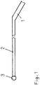
- An endoscope essentially consists of a handle 1, a tubular support 2 and a hood 3.
- the Fig. 1 shows an endoscope in a schematic representation.
- a digital camera 4 a digital camera 4
- a holder 5 a fork 6
- a transmission mechanism and at least one drive mechanism.
- the holder 5 with the digital camera 4 is rotatably disposed between the legs of the fork 6.
- the fork 6 is radially rotatably connected to the tubular support 2, so that the axes of rotation of the fork 6 and the holder 5 are arranged perpendicular to each other.
- This can conveniently take place simultaneously with a rotary drive 7, which is arranged in the tubular support 2.
- a drive 7 can be used with a ring shape.
- the Fig. 2 shows a rotatably mounted fork 6 with a rotatably mounted holder 5 with a digital camera 4 in a schematic representation.
- the holder 5 and a drivable roller 8 are connected to each other via a traction mechanism, wherein the roller 8 is manually operable or is coupled to a drive.
- a pulling means 9 a rope is preferably used.
- a part of the holder 5 is a role for the traction means 9th
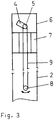
- the Fig. 3 shows drives and a traction mechanism for the fork 6 and the holder 5 in one basic representation.
- the drives are, for example, known stepper motors, wherein the rotation angle is greater than 360 °.
- the rotational angle of the stepping motors and thus the positions of the fork 6 and the holder 5 and, therefrom, the position of the image surface of the digital camera 4 can be determined by means of a control device connected to the stepper motors.
- the movement of the digital camera 4 is done, for example, via manually operated switch on the handle 1 as part of the tubular support 2 or on the tubular carrier. 2
- At the fork 6 and / or the holder 5 is at least one light source for visible light.
- connection cable for the digital camera 4 can be designed as a flexible printed circuit board with conductor tracks. For a mobility in the movements of the digital camera 4 and the fork 6 is given. This can also be ensured by an at least partially helical and / or helical arrangement of the connection cable.
- the flexible printed circuit board may further comprise printed conductors for the energy supply of the at least one lighting means.
- a hood 3 made of a visible light transparent material for the rotatably mounted fork 6 including the holder 5 with the digital camera 4 is arranged.
- the hood 3 is to a ball cap 3, wherein the ball cap 3 and the tubular support 2 are sealed together.
- the transmission mechanism is located in a tubular support element 10 of the fork 6 for pivoting the holder 5 with the digital camera 4.
- This consists of the first rotary and annular drive 7 for the tubular support member 10 and thus the fork 6 and a second drive 11 for the holder. 5
- the Fig. 4 shows the handle 1 with the drives 7, 11 in a schematic representation.
- each show in basic representations the Fig. 5 a rotatably mounted fork 6 with a rotatably mounted holder with a digital camera and the Fig. 6 a rotatably mounted holder 5 as a sliding joint.
- the transfer mechanism is a sliding crank 12 at least partially in the tubular support element 10.
- the sliding crank 12 is coupled to the translatory drive 11 as a second drive 11.
- this drive 11 are coupled to the crank 12 and the tubular support member 10 to the first rotary and annular drive 7. During a rotational movement, the holder 5 with the digital camera 4 is thereby simultaneously moved.
- the connecting cable for the digital camera 4 is at least partially in the crank 12 and thus inside the endoscope. Equivalent, at the same time, the connecting cables for the lamps can be guided accordingly.
- the drives are connected to at least one foot-operated switching device.
- This is, for example, a rocker with four switches for the respective movements of the digital camera 4 in the directions of movement predetermined by the two axes of rotation.
- the switch of the handle 1 can be omitted.
- a control device in the form of a known data processing system is connected to the drives 7, 11 and a device for viewing.
- the drives are controlled by the movement and position of the eye so that the area imaged by the digital camera 4 is determined by the eye position.
- the camera for determining the position and tracking the movement of at least one eye is part of a pair of glasses.
- the digital camera 4 of the endoscope is thereby positioned and moved according to the position and the movement of the eye.
- the switch of the handle 1 can be omitted.
- a control device in the form of a known data processing system is connected to the drives 7, 11 and a device for gesture recognition, so that the drives 7, 11 are controlled by the movement of a body part of a person.
- Gesture recognition is based on sensors worn by the person or at least one camera that picks up the person's movements.
- known acceleration or position sensors are used.
- the drives 7, 11 are controlled by the image taken by the person and a subsequent known image analysis in the data processing system.
- the holder 5 can simultaneously have electrically conductive elements at least for the operation of the digital camera 4 in the form of the electrical power supply. These are, for example, electrically conductive layers on surface areas of the holder 5. In addition, areas thereof may also be sliding contacts, so that a contact with the fork 6 is possible.
Landscapes
- Health & Medical Sciences (AREA)
- Life Sciences & Earth Sciences (AREA)
- Physics & Mathematics (AREA)
- Surgery (AREA)
- Optics & Photonics (AREA)
- Engineering & Computer Science (AREA)
- Biomedical Technology (AREA)
- Molecular Biology (AREA)
- Pathology (AREA)
- Nuclear Medicine, Radiotherapy & Molecular Imaging (AREA)
- Biophysics (AREA)
- Heart & Thoracic Surgery (AREA)
- Medical Informatics (AREA)
- Radiology & Medical Imaging (AREA)
- Animal Behavior & Ethology (AREA)
- General Health & Medical Sciences (AREA)
- Public Health (AREA)
- Veterinary Medicine (AREA)
- Astronomy & Astrophysics (AREA)
- General Physics & Mathematics (AREA)
- Multimedia (AREA)
- Endoscopes (AREA)
Description
- Die Erfindung betrifft Endoskope.
- Die heute im Einsatz befindlichen Endoskope haben alle eine eingeschränkte Beweglichkeit und können keine Rundumsicht anbieten. In den meisten Fällen gibt es starre Winkel-Endoskope. Die flexiblen Endoskope können nur bedingt frei gesteuert werden und sind gerade im Bereich ihres beweglichen Schaftes sehr anfällig für Korrosion. Derzeit ist im Bereich der starren Endoskopie noch die Stablinsen-Optik das Maß aller Dinge.
- Im Bereich der flexiblen Endoskope setzen sich zunehmend die Chip-on-the-tip-Endoskope durch. Trotzdem ist die Qualität der Stablinsen-Optiken mit aufgesetzter Drei-Chip-Kamera besser als die alleinigen Chip-on-the-tip-Endoskope.
- Es besteht eine eingeschränkte Beweglichkeit und Flexibilität der Endoskope.
- Durch die Druckschrift
EP 1 759 629 A1 ist ein Endoskop mit einem langgestreckten starren Schaft und einem optischen Abbildungssystem bekannt. Das optische Abbildungssystem ist dabei bezüglich des Schaftes um zumindest eine zweite Schwenkachse verschwenkbar ist, die von einer ersten Schwenkachse beabstandet ist und etwa quer zur Längsachse des Schaftes verläuft. Neben der Drehachse sind zwei unabhängig voneinander zu bedienende Schwenkachsen vorhanden. - Die Druckschrift
DE 201 13 031 U1 umfasst ein Videoendoskop mit einer drehbaren Videokamera. Die drehbare Videokamera ist mittels Schleifkontakten elektrisch mit einem ortsfesten Teil des Videoendoskops verbunden. - Die Druckschrift
WO 2010 / 097 315 A1 offenbart eine räumliche Steuerung eines bildgebenden endoskopischen Instrumentes, wobei das distale Ende des Instrumentes abhängig von der Anzeige der jeweiligen Position und vorgesehenen Aktion von einer motorisch angetriebenen Einrichtung gehaltert und bewegt wird. Dabei werden die Augenbewegungen der Bedienungsperson oder die Blickachse bei der Beobachtung der Anzeige nach der Eye-Tracking-Methode erfasst und zur Steuerung der Bildaufnahme und der Bildnachführung sowie der Anzeige verwendet. - Der im Patentanspruch 1 angegebenen Erfindung liegt die Aufgabe zugrunde, Objekte mit einem Endoskop einfach zu betrachten.
- Diese Aufgabe wird mit den im Patentanspruch 1 aufgeführten Merkmalen gelöst.
- Die Endoskope zeichnen sich insbesondere dadurch aus, dass Objekte mit den Endoskopen einfach und ohne Bewegung der Endoskope an sich betrachtbar sind.
- Dazu befindet sich ein drehbar gelagerter Halter mit einer Digitalkamera in einer drehbar gelagerten Gabel. Dabei ist die Gabel radial drehbar so angeordnet, dass die Drehachsen der Halterung und des Halters senkrecht zueinander angeordnet sind.
- Mittels einer Schubkurbel wenigstens bereichsweise in einem rohrförmigen Trägerelement der Gabel ist der Halter mit der Digitalkamera schwenkbar. Das Endoskop weist weiterhin einen ersten rotatorischen und ringförmigen Schrittmotor, wobei sowohl der Stator als auch der Rotor des Schrittmotors in Form eines Elektromotors ringförmig ausgebildet sind, für das rohrförmige Trägerelement und damit der Gabel und einen zweiten an die Schubkurbel gekoppelten translatorischen Schrittmotor für den Halter auf, wobei
- der translatorische Schrittmotor mit der Schubkurbel und das rohrförmige Trägerelement an den an den Rotor des ersten rotatorischen und ringförmigen Schrittmotor gekoppelt sind,
- sich das Anschlusskabel für die Digitalkamera wenigstens bereichsweise in der Schubkurbel und damit im Inneren des Endoskops befindet und
- die Schrittmotore mit einer Steuereinrichtung verbunden sind, so dass die Positionen der Gabel und des Halters sowie daraus die Position der Bildfläche der Digitalkamera bestimmbar sind.
- Darüber hinaus besitzt das Endoskop eine Haube aus einem für sichtbares Licht transparentem Material für die drehbar gelagerte Gabel einschließlich dem Halter mit der Digitalkamera, wobei die Abmessungen des Endoskopschafts nicht verändert sind.
- Damit ist die Digitalkamera in zwei Freiheitsgraden zu bewegen, wobei die Drehachsen senkrecht zueinander angeordnet sind. Über die Digitalkamera ist bis auf den Träger damit eine Rundumsicht möglich.
- Die Digitalkamera zeichnet sich vorteilhafterweise dadurch aus, dass das auf dem Bildsensor fallende Abbild gleichzeitig digital gewandelt wird. Die digitalen Daten lassen sich vielseitig verwenden. Diese können einfach gespeichert, verarbeitet und/oder sichtbar dargestellt werden. Das erfolgt vorteilhafterweise mittels eines bekannten Datenverarbeitungssystems beispielsweise in Form eines Mikrorechners.
- Günstigerweise weist das Endoskop den ersten rotatorischen und ringförmigen Antrieb für das rohrförmige Trägerelement auf, wobei sowohl der Stator als auch der Rotor des Antriebs in Form eines Elektromotors ringförmig ausgebildet sind.
- Die Daten können so vorteilhafterweise von der Digitalkamera über das Anschlusskabel im Träger und einem Griffstück des Endoskops am Ende des Endoskops abgenommen werden. Beispielsweise kann das Anschlusskabel weitergeführt sein oder kann an einem Verbinder am Griffstück enden, wobei das Anschlusskabel mit dem Verbinder verbunden ist.
- Durch die Schrittmotore sind die Positionen der Gabel und des Halters sowie daraus die Position der Bildfläche der Digitalkamera mittels einer mit den Schrittmotoren verbundenen Steuereinrichtung bestimmbar. In Verbindung mit einem Maßstab als Bestandteil des Endoskops sind damit auch Längen und daraus folgernd Größen bestimmbar.
- Das Anschlusskabel kann als flexible Leiterplatte mit Leiterbahnen ausgeführt sein. Damit ist eine Beweglichkeit bei den Bewegungen der Digitalkamera und der Gabel gegeben. Das kann auch durch eine wenigstens bereichsweise spiral- und/oder schraubenförmige Anordnung des Anschlusskabels gewährleistet werden.
- Das Anschlusskabel kann dabei entweder wenigstens eine Datenleitung oder wenigstens eine Datenleitung sowie eine Energieleitung umfassen.
- Damit ist ein sicherer Betrieb der Digitalkamera gewährleistet. Die Daten können verlustfrei, ohne Längenbegrenzung und einfach an ein Datenverarbeitungssystem weitergeleitet werden.
- Das Endoskop zeichnet sich weiterhin durch ein deutlich erweitertes Gesichtsfeld aus, das den Operateur in die Lage versetzt, in hoher Auflösung eine optimale minimal-invasive Chirurgie durchführen zu können. Abmessungen des Endoskopschafts werden nicht verändert.
Die Haube sichert, dass das Endoskop abgeschlossen und damit leicht desinfizierbar ist. - Vorteilhafte Ausgestaltungen der Erfindung sind in den Patentansprüchen 2 bis 10 angegeben.
- An der Gabel und/oder dem Halter befindet sich nach der Weiterbildung des Patentanspruchs 2 wenigstens ein Leuchtmittel für sichtbares Licht. Vorteilhafterweise wird durch das Leuchtmittel der Aufnahmebereich der Digitalkamera ausgeleuchtet. Dadurch ist ein kompaktes System zur Untersuchung vorhanden. Neben Leuchtmitteln für weißes Licht können auch Leuchtmittel für Licht anderer Farben in Form elektromagnetischer Strahlung einer bestimmten Wellenlänge eingesetzt werden. Natürlich sind auch Kombinationen verschiedener Leuchtmittel oder Leuchtmittel für mehrere Wellenlängen elektromagnetischer Strahlung zur Anwendung kommen. Die Sichtbarmachung bestimmter Objekte wird erhöht.
- Das Anschlusskabel ist nach der Weiterbildung des Patentanspruchs 3 günstigerweise eine flexible Leiterplatte, die einen flexiblen Träger und Leiterbahnen aufweist.
- Nach der Weiterbildung des Patentanspruchs 4 sind die Schrittmotore mit wenigstens einer fußbetätigbaren Schalteinrichtung verbunden. Der Nutzer des Endoskops steuert die Position der Digitalkamera über die fußbetätigbare Schalteinheit, so dass seine Hände für weitere Tätigkeiten frei sind.
- Nach der Weiterbildung des Patentanspruchs 5 ist eine Steuereinrichtung mit den Schrittmotoren und einer Vorrichtung zur Blickerfassung verbunden, so dass die Schrittmotore durch die Bewegung des Auges gesteuert wird und die durch die Digitalkamera abgebildete Fläche mittels der Augenposition bestimmt ist. Die Vorrichtung zur Blickerfassung ist auch als Eyetracker bekannt. Wenigstens eine Augenkamera trägt der Nutzer mittels einer speziellen Vorrichtung. Das kann auch eine Brille sein. Damit wird die Hand nicht zur Steuerung der Digitalkamera benötigt.
- Eine Steuereinrichtung ist nach der Weiterbildung des Patentanspruchs 6 mit den Schrittmotoren und einer Einrichtung zur Gestenerkennung verbunden, so dass die Schrittmotore durch die Bewegung eines Körperteiles gesteuert werden.
- Die Gestenerkennung basiert auf Sensoren, die von einer Person getragen werden, oder mindestens einer Kamera, die die Bewegungen einer Person aufnimmt.
- Der Halter weist nach der Weiterbildung des Patentanspruchs 7 gleichzeitig elektrisch leitende Elemente wenigstens zum Betrieb der Digitalkamera auf. Das sind wenigstens leitende Bestandteile zur Stromversorgung der Digitalkamera.
- Die Haube ist nach der Weiterbildung des Patentanspruchs 8 eine Kugelkappe. Weiterhin sind die Kugelkappe und ein Träger dicht miteinander verbunden. Die dichte Verbindung erlaubt eine einfache Säuberung und Desinfizierung des Endoskops, ohne das Bauteile davon beeinflusst werden.
- Wenigstens ein Bereich des Trägers ist nach der Weiterbildung des Patentanspruchs 9 ein starrer oder flexibler Bereich.
Ein Ausführungsbeispiel der Erfindung ist in den Zeichnungen jeweils prinzipiell dargestellt und wird im Folgenden näher beschrieben. - Es zeigen:
-
Fig. 1 ein Endoskop, -
Fig. 2 eine drehbar gelagerte Gabel mit einem drehbar gelagerten Halter mit einer Digitalkamera, -
Fig. 3 Antriebe und ein Zugmittelgetriebe für die Gabel und den Halter, -
Fig. 4 ein Griffstück mit Antrieben, -
Fig. 5 eine drehbar gelagerte Gabel mit einem drehbar gelagerten Halter mit einer Digitalkamera und -
Fig. 6 einen drehbar gelagerten Halter als Schubgelenk. - Ein Endoskop besteht im Wesentlichen aus einem Griffstück 1, einem rohrförmigen Träger 2 und einer Haube 3.
- Die
Fig. 1 zeigt ein Endoskop in einer prinzipiellen Darstellung. - Weitere Bestandteile des Endoskops sind eine Digitalkamera 4, ein Halter 5, eine Gabel 6, ein Übertragungsmechanismus und wenigstens ein Antriebsmechanismus.
- Der Halter 5 mit der Digitalkamera 4 ist drehbar zwischen den Schenkeln der Gabel 6 angeordnet. Die Gabel 6 ist radial drehbar mit dem rohrförmigen Träger 2 verbunden, so dass die Drehachsen der Gabel 6 und des Halters 5 senkrecht zueinander angeordnet sind. Das kann günstigerweise gleichzeitig mit einem rotatorischen Antrieb 7 erfolgen, der im rohrförmigen Träger 2 angeordnet ist. Günstigerweise kann dazu ein Antrieb 7 mit einer Ringform eingesetzt werden.
- Die
Fig. 2 zeigt dazu eine drehbar gelagerte Gabel 6 mit einem drehbar gelagerten Halter 5 mit einer Digitalkamera 4 in einer prinzipiellen Darstellung. - Im rohrförmigen Träger 2 befindet sich der Übertragungsmechanismus zum Schwenken des Halters 5 mit der Digitalkamera 4. Dazu sind der Halter 5 und eine antreibbare Rolle 8 über ein Zugmittelgetriebe miteinander verbunden, wobei die Rolle 8 handbetätigbar ist oder an einen Antrieb gekoppelt ist. Als Zugmittel 9 wird vorzugsweise ein Seil verwendet. Ein Teil des Halters 5 ist dazu eine Rolle für das Zugmittel 9.
- Die
Fig. 3 zeigt Antriebe und ein Zugmittelgetriebe für die Gabel 6 und den Halter 5 in einer prinzipiellen Darstellung.
Die Antriebe sind beispielsweise bekannte Schrittmotore, wobei deren Drehwinkel größer 360° ist. Dadurch sind die Drehwinkel der Schrittmotore und damit die Positionen der Gabel 6 und des Halters 5 sowie daraus die Position der Bildfläche der Digitalkamera 4 mittels einer mit den Schrittmotoren verbundenen Steuereinrichtung bestimmbar. Die Bewegung der Digitalkamera 4 erfolgt dazu beispielsweise über handbetätigbare Schalter an dem Griffstück 1 als Bestandteil des rohrförmigen Trägers 2 oder am rohrförmigem Träger 2. - An der Gabel 6 und/oder dem Halter 5 befindet sich wenigstens ein Leuchtmittel für sichtbares Licht.
- Das Anschlusskabel für die Digitalkamera 4 kann als flexible Leiterplatte mit Leiterbahnen ausgeführt sein. Damit ist eine Beweglichkeit bei den Bewegungen der Digitalkamera 4 und der Gabel 6 gegeben. Das kann auch durch eine wenigstens bereichsweise spiral- und/oder schraubenförmige Anordnung des Anschlusskabels gewährleistet werden. Die flexible Leiterplatte kann weiterhin Leiterbahnen für die Energieversorgung des wenigstens einen Leuchtmittels aufweisen.
- Weiterhin ist eine Haube 3 aus einem für sichtbares Licht transparentem Material für die drehbar gelagerte Gabel 6 einschließlich des Halters 5 mit der Digitalkamera 4 angeordnet. Die Haube 3 ist dazu eine Kugelkappe 3, wobei die Kugelkappe 3 und der rohrförmige Träger 2 dicht miteinander verbunden sind.
- In einer Ausführungsform befindet sich der Übertragungsmechanismus in einem rohrförmigen Trägerelement 10 der Gabel 6 zum Schwenken des Halters 5 mit der Digitalkamera 4.
- Der besteht dazu aus dem ersten rotatorischen und ringförmigen Antrieb 7 für das rohrförmige Trägerelement 10 und damit der Gabel 6 und einem zweiten Antrieb 11 für den Halter 5.
- Die
Fig. 4 zeigt dazu das Griffstück 1 mit den Antrieben 7, 11 in einer prinzipiellen Darstellung. - Weiterhin zeigen jeweils in prinzipiellen Darstellungen
dieFig. 5 eine drehbar gelagerte Gabel 6 mit einem drehbar gelagerten Halter mit einer Digitalkamera und
dieFig. 6 einen drehbar gelagerten Halter 5 als Schubgelenk. - Der Übertragungsmechanismus ist eine Schubkurbel 12 wenigstens bereichsweise im rohrförmigen Trägerelement 10. Die Schubkurbel 12 ist an den translatorischen Antrieb 11 als zweiten Antrieb 11 gekoppelt.
- Weiterhin sind dieser Antrieb 11 mit der Schubkurbel 12 und das rohrförmige Trägerelement 10 an den ersten rotatorischen und ringförmigen Antrieb 7 gekoppelt. Bei einer Drehbewegung wird damit gleichzeitig der Halter 5 mit der Digitalkamera 4 bewegt.
- Das Anschlusskabel für die Digitalkamera 4 befindet sich wenigstens bereichsweise in der Schubkurbel 12 und damit im Inneren des Endoskops. Äquivalent können gleichzeitig die Anschlusskabel für die Leuchtmittel dementsprechend geführt werden.
- In einer weiteren Ausführungsform sind die Antriebe mit wenigstens einer fußbetätigbaren Schalteinrichtung verbunden. Das ist beispielsweise eine Wippe mit vier Schaltern für die jeweiligen Bewegungen der Digitalkamera 4 in den durch die beiden Drehachsen vorgegebenen Bewegungsrichtungen. Dabei können die Schalter des Griffstücks 1 entfallen.
- In einer weiteren Ausführungsform ist eine Steuereinrichtung in Form eines bekannten Datenverarbeitungssystems mit den Antrieben 7, 11 und einer Vorrichtung zur Blickerfassung verbunden. Die Antriebe werden durch die Bewegung und die Stellung des Auges gesteuert, so dass die durch die Digitalkamera 4 abgebildete Fläche mittels der Augenposition bestimmt ist. Die Kamera zur Bestimmung der Stellung und der Verfolgung der Bewegung wenigstens eines Auges ist dazu ein Bestandteil einer Brille. Die Digitalkamera 4 des Endoskops wird dabei entsprechend der Stellung und der Bewegung des Auges positioniert und bewegt. Dabei können die Schalter des Griffstücks 1 entfallen.
- In einer weiteren Ausführungsform ist eine Steuereinrichtung in Form eines bekannten Datenverarbeitungssystems mit den Antrieben 7, 11 und einer Einrichtung zur Gestenerkennung verbunden, so dass die Antriebe 7, 11 durch die Bewegung eines Körperteiles einer Person gesteuert wird.
- Die Gestenerkennung basiert auf Sensoren, die von der Person getragen werden, oder mindestens einer Kamera, die die Bewegungen der Person aufnimmt. Im ersten Fall kommen bekannte Beschleunigungs- oder Positionssensoren zum Einsatz. Im zweiten Fall werden die Antriebe 7, 11 durch das von der Person aufgenommene Abbild und einer nachfolgenden bekannten Bildanalyse im Datenverarbeitungssystem gesteuert.
- In einer weiteren Ausführungsform kann der Halter 5 gleichzeitig elektrisch leitende Elemente wenigstens zum Betrieb der Digitalkamera 4 in Form der elektrischen Stromversorgung aufweisen. Das sind beispielsweise elektrisch leitende Schichten auf Oberflächenbereichen des Halters 5. Darüber hinaus können Bereiche davon auch Schleifkontakte sein, so dass eine Kontaktierung an der Gabel 6 möglich ist.
Claims (9)
- Endoskop mit- einem in einer drehbar gelagerten Gabel (6) drehbar gelagerten Halter (5) mit einer Digitalkamera (4), wobei die Gabel (6) radial drehbar so angeordnet ist, dass die Drehachsen der Gabel (6) und des Halters (5) senkrecht zueinander angeordnet sind,- einer Schubkurbel (12) wenigstens bereichsweise in einem rohrförmigen Trägerelement (10) der Gabel (6) zum Schwenken des Halters (5) mit der Digitalkamera (4),- einem ersten rotatorischen und ringförmigen Schrittmotor (7), wobei sowohl der Stator als auch der Rotor des Schrittmotors (7) in Form eines Elektromotors ringförmig ausgebildet sind, für das rohrförmige Trägerelement (10) und damit der Gabel (6) und- einem zweiten an die Schubkurbel (12) gekoppelten translatorischen Schrittmotor (11) für den Halter (5), wobei der translatorische Schrittmotor (11) mit der Schubkurbel und das rohrförmige Trägerelement (10) an den Rotor des ersten rotatorischen und ringförmigen Schrittmotor (7) gekoppelt sind, sich das Anschlusskabel für die Digitalkamera (4) wenigstens bereichsweise in der Schubkurbel (12) und damit im Inneren des Endoskops befindet und die Schrittmotore (7, 11) mit einer Steuereinrichtung verbunden sind, so dass die Positionen der Gabel (6) und des Halters (5) sowie daraus die Position der Bildfläche der Digitalkamera (4) bestimmbar sind, und- einer Haube (3) aus einem für sichtbares Licht transparentem Material für die drehbar gelagerte Gabel (6) einschließlich dem Halter (5) mit der Digitalkamera (4), wobei die Abmessungen des Endoskopschafts nicht verändert sind.
- Endoskop nach Patentanspruch 1, dadurch gekennzeichnet, dass sich an der Gabel (6) und/oder dem Halter (5) wenigstens ein Leuchtmittel für sichtbares Licht befindet.
- Endoskop nach Patentanspruch 1, dadurch gekennzeichnet, dass das Anschlusskabel eine flexible Leiterplatte ist und dass die flexible Leiterplatte einen flexiblen Träger und Leiterbahnen aufweist.
- Endoskop nach Patentanspruch 1, dadurch gekennzeichnet, dass die Schrittmotore (7, 11) mit wenigstens einer fußbetätigbaren Schalteinrichtung verbunden sind.
- Endoskop nach Patentanspruch 1, dadurch gekennzeichnet, dass eine Steuereinrichtung mit den Schrittmotoren (7, 11) und einer Vorrichtung zur Blickerfassung verbunden ist, so dass die Schrittmore (7, 11) durch die Bewegung des Auges gesteuert wird und die durch die Digitalkamera (4) abgebildete Fläche mittels der Augenposition bestimmt ist.
- Endoskop nach Patentanspruch 1, dadurch gekennzeichnet, dass eine Steuereinrichtung mit den Schrittmotoren (7, 11) und einer Einrichtung zur Gestenerkennung verbunden ist, so dass die Antriebe durch die Bewegung eines Körperteiles gesteuert wird.
- Endoskop nach Patentanspruch 1, dadurch gekennzeichnet, dass der Halter (5) gleichzeitig elektrisch leitende Elemente wenigstens zum Betrieb der Digitalkamera (4) aufweist.
- Endoskop nach Patentanspruch 1, dadurch gekennzeichnet, dass die Haube (3) eine Kugelkappe (3) ist und dass die Kugelkappe (3) und ein Träger dicht miteinander verbunden sind.
- Endoskop nach Patentanspruch 8, dadurch gekennzeichnet, dass wenigstens ein Bereich des Trägers (2) ein starrer oder flexibler Bereich ist.
Applications Claiming Priority (2)
| Application Number | Priority Date | Filing Date | Title |
|---|---|---|---|
| DE102011017536 | 2011-04-26 | ||
| PCT/EP2012/057667 WO2012146664A1 (de) | 2011-04-26 | 2012-04-26 | Endoskop |
Publications (2)
| Publication Number | Publication Date |
|---|---|
| EP2701573A1 EP2701573A1 (de) | 2014-03-05 |
| EP2701573B1 true EP2701573B1 (de) | 2018-08-22 |
Family
ID=46017863
Family Applications (1)
| Application Number | Title | Priority Date | Filing Date |
|---|---|---|---|
| EP12717292.2A Not-in-force EP2701573B1 (de) | 2011-04-26 | 2012-04-26 | Endoskop |
Country Status (3)
| Country | Link |
|---|---|
| EP (1) | EP2701573B1 (de) |
| DE (1) | DE102012206963A1 (de) |
| WO (1) | WO2012146664A1 (de) |
Cited By (1)
| Publication number | Priority date | Publication date | Assignee | Title |
|---|---|---|---|---|
| DE102019102599A1 (de) * | 2019-02-01 | 2020-08-06 | Konstantin Bob | Endoskop mit distalem Schwenkmechanismus und Feinjustierung |
Families Citing this family (14)
| Publication number | Priority date | Publication date | Assignee | Title |
|---|---|---|---|---|
| DE202014008760U1 (de) | 2014-11-05 | 2016-02-08 | Jt-Elektronik Gmbh | Vorrichtung zur Einstellung des Blickwinkels einer Kanalinspektionskamera |
| US10517470B2 (en) * | 2016-05-13 | 2019-12-31 | Karl Storz Endovision, Inc. | Optical instrument and articulating image sensing apparatus therefor |
| CN106214114B (zh) * | 2016-09-26 | 2017-08-25 | 青岛市第三人民医院 | 一种耳鼻喉科检查装置 |
| JP2019530508A (ja) | 2016-09-29 | 2019-10-24 | 270 サージカル リミテッド | 剛性医療手術用照明装置 |
| GB2563240B (en) | 2017-06-07 | 2019-12-18 | Egyptian Commerce Company Eco | Laparoscopic camera |
| DE102017119691B4 (de) * | 2017-08-28 | 2024-03-21 | Schölly Fiberoptic GmbH | Endoskop mit einem verdrehbaren, elektrischen Verbindungselement |
| FR3077195B1 (fr) * | 2018-01-29 | 2024-08-23 | Foretec Societe Forezienne De Tech | Camera d'endoscopie industrielle rotative a tete pivotante |
| DE102020115257B3 (de) | 2020-06-09 | 2021-10-07 | Karl Storz Se & Co. Kg | Endoskop mit schwenkbarer Bilderfassungseinrichtung |
| DE102020115258B3 (de) | 2020-06-09 | 2021-09-16 | Karl Storz Se & Co. Kg | Endoskop mit schwenkbarer Bilderfassungseinrichtung |
| CN115460338B (zh) * | 2022-09-09 | 2024-05-24 | 江苏三棱智慧物联发展股份有限公司 | 一种智能物联安防管理方法和系统 |
| CN116350157A (zh) * | 2023-04-23 | 2023-06-30 | 上海宇度医学科技股份有限公司 | 一种内窥镜 |
| CN116172674B (zh) * | 2023-04-26 | 2023-08-18 | 上海宇度医学科技股份有限公司 | 一种集成切割装置的内窥镜及切割装置 |
| DE102023123953B3 (de) | 2023-09-06 | 2024-10-24 | Karl Storz Se & Co. Kg | Endoskop mit einem starren oder flexiblen Schaftrohr |
| CN117017172B (zh) * | 2023-10-09 | 2023-12-22 | 上海宇度医学科技股份有限公司 | 一种内窥镜 |
Citations (1)
| Publication number | Priority date | Publication date | Assignee | Title |
|---|---|---|---|---|
| WO2010097315A1 (de) * | 2009-02-24 | 2010-09-02 | Reiner Kunz | Navigation endoskopischer vorrichtungen mittels eye-tracker |
Family Cites Families (7)
| Publication number | Priority date | Publication date | Assignee | Title |
|---|---|---|---|---|
| US6413209B1 (en) * | 1995-09-15 | 2002-07-02 | Med Images, Inc. | Imaging system with condensation control |
| CA2321488C (en) * | 1998-02-19 | 2008-02-12 | California Institute Of Technology | Apparatus and method for providing spherical viewing during endoscopic procedures |
| DE20113031U1 (de) * | 2001-08-04 | 2001-12-20 | Olympus Winter & Ibe Gmbh, 22045 Hamburg | Videoendoskop mit drehbarer Videokamera |
| WO2005120330A1 (ja) * | 2004-06-08 | 2005-12-22 | Nisco Co., Ltd. | 硬性電子内視鏡 |
| CA2533549C (en) * | 2005-01-21 | 2009-12-15 | Karl Storz Development Corp. | Variable direction of view instrument with distal image sensor |
| DE102005015522A1 (de) * | 2005-04-04 | 2006-10-05 | Karl Storz Gmbh & Co. Kg | Intrakorporale Videokapsel mit schwenkbarem Bildaufnehmer |
| EP1759629B1 (de) * | 2005-08-31 | 2014-04-02 | Karl Storz GmbH & Co. KG | Endoskop mit variabler Blickrichtung |
-
2012
- 2012-04-26 EP EP12717292.2A patent/EP2701573B1/de not_active Not-in-force
- 2012-04-26 WO PCT/EP2012/057667 patent/WO2012146664A1/de not_active Ceased
- 2012-04-26 DE DE102012206963A patent/DE102012206963A1/de not_active Withdrawn
Patent Citations (1)
| Publication number | Priority date | Publication date | Assignee | Title |
|---|---|---|---|---|
| WO2010097315A1 (de) * | 2009-02-24 | 2010-09-02 | Reiner Kunz | Navigation endoskopischer vorrichtungen mittels eye-tracker |
Cited By (1)
| Publication number | Priority date | Publication date | Assignee | Title |
|---|---|---|---|---|
| DE102019102599A1 (de) * | 2019-02-01 | 2020-08-06 | Konstantin Bob | Endoskop mit distalem Schwenkmechanismus und Feinjustierung |
Also Published As
| Publication number | Publication date |
|---|---|
| DE102012206963A1 (de) | 2012-10-31 |
| EP2701573A1 (de) | 2014-03-05 |
| WO2012146664A1 (de) | 2012-11-01 |
Similar Documents
| Publication | Publication Date | Title |
|---|---|---|
| WO2012146664A1 (de) | Endoskop | |
| DE69922791T2 (de) | Gerät zur bereitstellung eines spherischen sehfeldes während endoskopischen eingriffen | |
| DE102019004433A1 (de) | Videoendoskop und Griff für ein Videoendoskop | |
| CN101513360B (zh) | 机械手操作系统 | |
| EP1997421B1 (de) | Videoendoskop | |
| EP1074214B1 (de) | Gerät zur Augenuntersuchung mit einer Scheimpflugkamera und einem Spaltprojektor | |
| EP2850996B1 (de) | Vorrichtung zum Aufnehmen eines Bildes eines Objektfelds an einem menschlichen oder tierischen Körper | |
| EP3073307B1 (de) | Vorrichtung zum aufnehmen eines bildes eines objektfelds an einem menschlichen oder tierischen körper | |
| DE10004264C2 (de) | Vorrichtung zur intrakorporalen, minimal-invasiven Behandlung eines Patienten | |
| DE202010009234U1 (de) | Endoskopiervorrichtung | |
| WO2013156025A1 (de) | Rotationsvorrichtung und verfahren zum rotieren eines endoskops | |
| DE102015121017B4 (de) | Medizinische Beobachtungsvorrichtung mit einer Bedieneinheit sowie Verwendung eines Eingabemoduls | |
| EP1690492A1 (de) | Instrument mit variabler Blickrichtung mit On-board-Aktuatoren | |
| DE102005008153A1 (de) | Endoskopische Beobachtungseinrichtung | |
| DE102010041857A1 (de) | Stereoendoskop | |
| DE102020115258B3 (de) | Endoskop mit schwenkbarer Bilderfassungseinrichtung | |
| DE102012206412A1 (de) | Rotationsvorrichtung und Verfahren zum Rotieren eines Endoskops | |
| DE112017005662T5 (de) | Gelenkantriebsaktuator und medizinisches system | |
| EP2477528B1 (de) | Handstück-kamera | |
| WO2012041445A1 (de) | Sensoreinheit für ein stereoendoskop und stereoendoskopiesystem | |
| EP3851897B1 (de) | Optisches beobachtungsinstrument | |
| DE202014000037U1 (de) | Endoskopievorrichtung | |
| JP7094746B2 (ja) | 医療用観察装置 | |
| DE102015114742B4 (de) | Kinematik für ein intrakorporal angetriebenes Instrument eines Endoskops | |
| DE7440701U (de) | Endoskop, insbesondere Laryngoskop und Epipharyngoskop |
Legal Events
| Date | Code | Title | Description |
|---|---|---|---|
| PUAI | Public reference made under article 153(3) epc to a published international application that has entered the european phase |
Free format text: ORIGINAL CODE: 0009012 |
|
| 17P | Request for examination filed |
Effective date: 20131126 |
|
| AK | Designated contracting states |
Kind code of ref document: A1 Designated state(s): AL AT BE BG CH CY CZ DE DK EE ES FI FR GB GR HR HU IE IS IT LI LT LU LV MC MK MT NL NO PL PT RO RS SE SI SK SM TR |
|
| RIN1 | Information on inventor provided before grant (corrected) |
Inventor name: BOESE, AXEL Inventor name: ARENS, CHRISTOPH |
|
| DAX | Request for extension of the european patent (deleted) | ||
| STAA | Information on the status of an ep patent application or granted ep patent |
Free format text: STATUS: EXAMINATION IS IN PROGRESS |
|
| 17Q | First examination report despatched |
Effective date: 20170113 |
|
| GRAP | Despatch of communication of intention to grant a patent |
Free format text: ORIGINAL CODE: EPIDOSNIGR1 |
|
| STAA | Information on the status of an ep patent application or granted ep patent |
Free format text: STATUS: GRANT OF PATENT IS INTENDED |
|
| INTG | Intention to grant announced |
Effective date: 20180305 |
|
| GRAS | Grant fee paid |
Free format text: ORIGINAL CODE: EPIDOSNIGR3 |
|
| GRAA | (expected) grant |
Free format text: ORIGINAL CODE: 0009210 |
|
| STAA | Information on the status of an ep patent application or granted ep patent |
Free format text: STATUS: THE PATENT HAS BEEN GRANTED |
|
| AK | Designated contracting states |
Kind code of ref document: B1 Designated state(s): AL AT BE BG CH CY CZ DE DK EE ES FI FR GB GR HR HU IE IS IT LI LT LU LV MC MK MT NL NO PL PT RO RS SE SI SK SM TR |
|
| REG | Reference to a national code |
Ref country code: GB Ref legal event code: FG4D Free format text: NOT ENGLISH |
|
| REG | Reference to a national code |
Ref country code: CH Ref legal event code: EP |
|
| REG | Reference to a national code |
Ref country code: AT Ref legal event code: REF Ref document number: 1031488 Country of ref document: AT Kind code of ref document: T Effective date: 20180915 |
|
| REG | Reference to a national code |
Ref country code: IE Ref legal event code: FG4D Free format text: LANGUAGE OF EP DOCUMENT: GERMAN |
|
| REG | Reference to a national code |
Ref country code: DE Ref legal event code: R096 Ref document number: 502012013290 Country of ref document: DE |
|
| REG | Reference to a national code |
Ref country code: NL Ref legal event code: MP Effective date: 20180822 |
|
| REG | Reference to a national code |
Ref country code: LT Ref legal event code: MG4D |
|
| PG25 | Lapsed in a contracting state [announced via postgrant information from national office to epo] |
Ref country code: LT Free format text: LAPSE BECAUSE OF FAILURE TO SUBMIT A TRANSLATION OF THE DESCRIPTION OR TO PAY THE FEE WITHIN THE PRESCRIBED TIME-LIMIT Effective date: 20180822 Ref country code: RS Free format text: LAPSE BECAUSE OF FAILURE TO SUBMIT A TRANSLATION OF THE DESCRIPTION OR TO PAY THE FEE WITHIN THE PRESCRIBED TIME-LIMIT Effective date: 20180822 Ref country code: IS Free format text: LAPSE BECAUSE OF FAILURE TO SUBMIT A TRANSLATION OF THE DESCRIPTION OR TO PAY THE FEE WITHIN THE PRESCRIBED TIME-LIMIT Effective date: 20181222 Ref country code: NO Free format text: LAPSE BECAUSE OF FAILURE TO SUBMIT A TRANSLATION OF THE DESCRIPTION OR TO PAY THE FEE WITHIN THE PRESCRIBED TIME-LIMIT Effective date: 20181122 Ref country code: GR Free format text: LAPSE BECAUSE OF FAILURE TO SUBMIT A TRANSLATION OF THE DESCRIPTION OR TO PAY THE FEE WITHIN THE PRESCRIBED TIME-LIMIT Effective date: 20181123 Ref country code: SE Free format text: LAPSE BECAUSE OF FAILURE TO SUBMIT A TRANSLATION OF THE DESCRIPTION OR TO PAY THE FEE WITHIN THE PRESCRIBED TIME-LIMIT Effective date: 20180822 Ref country code: FI Free format text: LAPSE BECAUSE OF FAILURE TO SUBMIT A TRANSLATION OF THE DESCRIPTION OR TO PAY THE FEE WITHIN THE PRESCRIBED TIME-LIMIT Effective date: 20180822 Ref country code: BG Free format text: LAPSE BECAUSE OF FAILURE TO SUBMIT A TRANSLATION OF THE DESCRIPTION OR TO PAY THE FEE WITHIN THE PRESCRIBED TIME-LIMIT Effective date: 20181122 Ref country code: NL Free format text: LAPSE BECAUSE OF FAILURE TO SUBMIT A TRANSLATION OF THE DESCRIPTION OR TO PAY THE FEE WITHIN THE PRESCRIBED TIME-LIMIT Effective date: 20180822 |
|
| PG25 | Lapsed in a contracting state [announced via postgrant information from national office to epo] |
Ref country code: HR Free format text: LAPSE BECAUSE OF FAILURE TO SUBMIT A TRANSLATION OF THE DESCRIPTION OR TO PAY THE FEE WITHIN THE PRESCRIBED TIME-LIMIT Effective date: 20180822 Ref country code: AL Free format text: LAPSE BECAUSE OF FAILURE TO SUBMIT A TRANSLATION OF THE DESCRIPTION OR TO PAY THE FEE WITHIN THE PRESCRIBED TIME-LIMIT Effective date: 20180822 Ref country code: LV Free format text: LAPSE BECAUSE OF FAILURE TO SUBMIT A TRANSLATION OF THE DESCRIPTION OR TO PAY THE FEE WITHIN THE PRESCRIBED TIME-LIMIT Effective date: 20180822 |
|
| PG25 | Lapsed in a contracting state [announced via postgrant information from national office to epo] |
Ref country code: RO Free format text: LAPSE BECAUSE OF FAILURE TO SUBMIT A TRANSLATION OF THE DESCRIPTION OR TO PAY THE FEE WITHIN THE PRESCRIBED TIME-LIMIT Effective date: 20180822 Ref country code: IT Free format text: LAPSE BECAUSE OF FAILURE TO SUBMIT A TRANSLATION OF THE DESCRIPTION OR TO PAY THE FEE WITHIN THE PRESCRIBED TIME-LIMIT Effective date: 20180822 Ref country code: CZ Free format text: LAPSE BECAUSE OF FAILURE TO SUBMIT A TRANSLATION OF THE DESCRIPTION OR TO PAY THE FEE WITHIN THE PRESCRIBED TIME-LIMIT Effective date: 20180822 Ref country code: ES Free format text: LAPSE BECAUSE OF FAILURE TO SUBMIT A TRANSLATION OF THE DESCRIPTION OR TO PAY THE FEE WITHIN THE PRESCRIBED TIME-LIMIT Effective date: 20180822 Ref country code: PL Free format text: LAPSE BECAUSE OF FAILURE TO SUBMIT A TRANSLATION OF THE DESCRIPTION OR TO PAY THE FEE WITHIN THE PRESCRIBED TIME-LIMIT Effective date: 20180822 Ref country code: EE Free format text: LAPSE BECAUSE OF FAILURE TO SUBMIT A TRANSLATION OF THE DESCRIPTION OR TO PAY THE FEE WITHIN THE PRESCRIBED TIME-LIMIT Effective date: 20180822 |
|
| REG | Reference to a national code |
Ref country code: DE Ref legal event code: R097 Ref document number: 502012013290 Country of ref document: DE |
|
| PG25 | Lapsed in a contracting state [announced via postgrant information from national office to epo] |
Ref country code: DK Free format text: LAPSE BECAUSE OF FAILURE TO SUBMIT A TRANSLATION OF THE DESCRIPTION OR TO PAY THE FEE WITHIN THE PRESCRIBED TIME-LIMIT Effective date: 20180822 Ref country code: SM Free format text: LAPSE BECAUSE OF FAILURE TO SUBMIT A TRANSLATION OF THE DESCRIPTION OR TO PAY THE FEE WITHIN THE PRESCRIBED TIME-LIMIT Effective date: 20180822 Ref country code: SK Free format text: LAPSE BECAUSE OF FAILURE TO SUBMIT A TRANSLATION OF THE DESCRIPTION OR TO PAY THE FEE WITHIN THE PRESCRIBED TIME-LIMIT Effective date: 20180822 |
|
| PLBE | No opposition filed within time limit |
Free format text: ORIGINAL CODE: 0009261 |
|
| STAA | Information on the status of an ep patent application or granted ep patent |
Free format text: STATUS: NO OPPOSITION FILED WITHIN TIME LIMIT |
|
| 26N | No opposition filed |
Effective date: 20190523 |
|
| PG25 | Lapsed in a contracting state [announced via postgrant information from national office to epo] |
Ref country code: SI Free format text: LAPSE BECAUSE OF FAILURE TO SUBMIT A TRANSLATION OF THE DESCRIPTION OR TO PAY THE FEE WITHIN THE PRESCRIBED TIME-LIMIT Effective date: 20180822 |
|
| REG | Reference to a national code |
Ref country code: CH Ref legal event code: PL |
|
| REG | Reference to a national code |
Ref country code: BE Ref legal event code: MM Effective date: 20190430 |
|
| PG25 | Lapsed in a contracting state [announced via postgrant information from national office to epo] |
Ref country code: LU Free format text: LAPSE BECAUSE OF NON-PAYMENT OF DUE FEES Effective date: 20190426 Ref country code: MC Free format text: LAPSE BECAUSE OF FAILURE TO SUBMIT A TRANSLATION OF THE DESCRIPTION OR TO PAY THE FEE WITHIN THE PRESCRIBED TIME-LIMIT Effective date: 20180822 |
|
| PG25 | Lapsed in a contracting state [announced via postgrant information from national office to epo] |
Ref country code: LI Free format text: LAPSE BECAUSE OF NON-PAYMENT OF DUE FEES Effective date: 20190430 Ref country code: CH Free format text: LAPSE BECAUSE OF NON-PAYMENT OF DUE FEES Effective date: 20190430 |
|
| PG25 | Lapsed in a contracting state [announced via postgrant information from national office to epo] |
Ref country code: BE Free format text: LAPSE BECAUSE OF NON-PAYMENT OF DUE FEES Effective date: 20190430 |
|
| PG25 | Lapsed in a contracting state [announced via postgrant information from national office to epo] |
Ref country code: TR Free format text: LAPSE BECAUSE OF FAILURE TO SUBMIT A TRANSLATION OF THE DESCRIPTION OR TO PAY THE FEE WITHIN THE PRESCRIBED TIME-LIMIT Effective date: 20180822 |
|
| PG25 | Lapsed in a contracting state [announced via postgrant information from national office to epo] |
Ref country code: IE Free format text: LAPSE BECAUSE OF NON-PAYMENT OF DUE FEES Effective date: 20190426 |
|
| PG25 | Lapsed in a contracting state [announced via postgrant information from national office to epo] |
Ref country code: PT Free format text: LAPSE BECAUSE OF FAILURE TO SUBMIT A TRANSLATION OF THE DESCRIPTION OR TO PAY THE FEE WITHIN THE PRESCRIBED TIME-LIMIT Effective date: 20181222 |
|
| REG | Reference to a national code |
Ref country code: AT Ref legal event code: MM01 Ref document number: 1031488 Country of ref document: AT Kind code of ref document: T Effective date: 20190426 |
|
| PG25 | Lapsed in a contracting state [announced via postgrant information from national office to epo] |
Ref country code: AT Free format text: LAPSE BECAUSE OF NON-PAYMENT OF DUE FEES Effective date: 20190426 |
|
| PG25 | Lapsed in a contracting state [announced via postgrant information from national office to epo] |
Ref country code: CY Free format text: LAPSE BECAUSE OF FAILURE TO SUBMIT A TRANSLATION OF THE DESCRIPTION OR TO PAY THE FEE WITHIN THE PRESCRIBED TIME-LIMIT Effective date: 20180822 |
|
| PG25 | Lapsed in a contracting state [announced via postgrant information from national office to epo] |
Ref country code: MT Free format text: LAPSE BECAUSE OF FAILURE TO SUBMIT A TRANSLATION OF THE DESCRIPTION OR TO PAY THE FEE WITHIN THE PRESCRIBED TIME-LIMIT Effective date: 20180822 Ref country code: HU Free format text: LAPSE BECAUSE OF FAILURE TO SUBMIT A TRANSLATION OF THE DESCRIPTION OR TO PAY THE FEE WITHIN THE PRESCRIBED TIME-LIMIT; INVALID AB INITIO Effective date: 20120426 |
|
| PG25 | Lapsed in a contracting state [announced via postgrant information from national office to epo] |
Ref country code: MK Free format text: LAPSE BECAUSE OF FAILURE TO SUBMIT A TRANSLATION OF THE DESCRIPTION OR TO PAY THE FEE WITHIN THE PRESCRIBED TIME-LIMIT Effective date: 20180822 |
|
| PGFP | Annual fee paid to national office [announced via postgrant information from national office to epo] |
Ref country code: GB Payment date: 20220411 Year of fee payment: 11 Ref country code: FR Payment date: 20220408 Year of fee payment: 11 Ref country code: DE Payment date: 20220302 Year of fee payment: 11 |
|
| REG | Reference to a national code |
Ref country code: DE Ref legal event code: R119 Ref document number: 502012013290 Country of ref document: DE |
|
| GBPC | Gb: european patent ceased through non-payment of renewal fee |
Effective date: 20230426 |
|
| PG25 | Lapsed in a contracting state [announced via postgrant information from national office to epo] |
Ref country code: GB Free format text: LAPSE BECAUSE OF NON-PAYMENT OF DUE FEES Effective date: 20230426 |
|
| PG25 | Lapsed in a contracting state [announced via postgrant information from national office to epo] |
Ref country code: GB Free format text: LAPSE BECAUSE OF NON-PAYMENT OF DUE FEES Effective date: 20230426 Ref country code: FR Free format text: LAPSE BECAUSE OF NON-PAYMENT OF DUE FEES Effective date: 20230430 Ref country code: DE Free format text: LAPSE BECAUSE OF NON-PAYMENT OF DUE FEES Effective date: 20231103 |