EP2700882A2 - Purificateur d'air d'un dispositif d'aspiration de vapeur - Google Patents
Purificateur d'air d'un dispositif d'aspiration de vapeur Download PDFInfo
- Publication number
- EP2700882A2 EP2700882A2 EP13179949.6A EP13179949A EP2700882A2 EP 2700882 A2 EP2700882 A2 EP 2700882A2 EP 13179949 A EP13179949 A EP 13179949A EP 2700882 A2 EP2700882 A2 EP 2700882A2
- Authority
- EP
- European Patent Office
- Prior art keywords
- air
- air cleaner
- unit
- cleaner unit
- elements
- Prior art date
- Legal status (The legal status is an assumption and is not a legal conclusion. Google has not performed a legal analysis and makes no representation as to the accuracy of the status listed.)
- Granted
Links
- 239000003517 fume Substances 0.000 title claims description 6
- 238000010411 cooking Methods 0.000 title 1
- 238000004887 air purification Methods 0.000 claims abstract description 11
- 238000004140 cleaning Methods 0.000 claims description 14
- 238000000605 extraction Methods 0.000 claims description 4
- 235000019645 odor Nutrition 0.000 description 24
- ORQBXQOJMQIAOY-UHFFFAOYSA-N nobelium Chemical compound [No] ORQBXQOJMQIAOY-UHFFFAOYSA-N 0.000 description 17
- OKTJSMMVPCPJKN-UHFFFAOYSA-N Carbon Chemical compound [C] OKTJSMMVPCPJKN-UHFFFAOYSA-N 0.000 description 10
- 238000006243 chemical reaction Methods 0.000 description 9
- 230000001681 protective effect Effects 0.000 description 6
- 239000000126 substance Substances 0.000 description 6
- 239000003054 catalyst Substances 0.000 description 4
- 239000000463 material Substances 0.000 description 4
- CBENFWSGALASAD-UHFFFAOYSA-N Ozone Chemical compound [O-][O+]=O CBENFWSGALASAD-UHFFFAOYSA-N 0.000 description 2
- 239000012535 impurity Substances 0.000 description 2
- 238000009434 installation Methods 0.000 description 2
- 238000005457 optimization Methods 0.000 description 2
- 239000007795 chemical reaction product Substances 0.000 description 1
- 238000011109 contamination Methods 0.000 description 1
- 230000008878 coupling Effects 0.000 description 1
- 238000010168 coupling process Methods 0.000 description 1
- 238000005859 coupling reaction Methods 0.000 description 1
- 230000000694 effects Effects 0.000 description 1
- 238000010292 electrical insulation Methods 0.000 description 1
- 239000003344 environmental pollutant Substances 0.000 description 1
- 210000003746 feather Anatomy 0.000 description 1
- 238000001914 filtration Methods 0.000 description 1
- -1 for example Substances 0.000 description 1
- 239000004519 grease Substances 0.000 description 1
- 231100000719 pollutant Toxicity 0.000 description 1
- 230000000717 retained effect Effects 0.000 description 1
- XLYOFNOQVPJJNP-UHFFFAOYSA-N water Substances O XLYOFNOQVPJJNP-UHFFFAOYSA-N 0.000 description 1
Images

Classifications
-
- F—MECHANICAL ENGINEERING; LIGHTING; HEATING; WEAPONS; BLASTING
- F24—HEATING; RANGES; VENTILATING
- F24C—DOMESTIC STOVES OR RANGES ; DETAILS OF DOMESTIC STOVES OR RANGES, OF GENERAL APPLICATION
- F24C15/00—Details
- F24C15/20—Removing cooking fumes
- F24C15/2035—Arrangement or mounting of filters
-
- B—PERFORMING OPERATIONS; TRANSPORTING
- B03—SEPARATION OF SOLID MATERIALS USING LIQUIDS OR USING PNEUMATIC TABLES OR JIGS; MAGNETIC OR ELECTROSTATIC SEPARATION OF SOLID MATERIALS FROM SOLID MATERIALS OR FLUIDS; SEPARATION BY HIGH-VOLTAGE ELECTRIC FIELDS
- B03C—MAGNETIC OR ELECTROSTATIC SEPARATION OF SOLID MATERIALS FROM SOLID MATERIALS OR FLUIDS; SEPARATION BY HIGH-VOLTAGE ELECTRIC FIELDS
- B03C3/00—Separating dispersed particles from gases or vapour, e.g. air, by electrostatic effect
- B03C3/02—Plant or installations having external electricity supply
- B03C3/04—Plant or installations having external electricity supply dry type
- B03C3/08—Plant or installations having external electricity supply dry type characterised by presence of stationary flat electrodes arranged with their flat surfaces parallel to the gas stream
-
- B—PERFORMING OPERATIONS; TRANSPORTING
- B03—SEPARATION OF SOLID MATERIALS USING LIQUIDS OR USING PNEUMATIC TABLES OR JIGS; MAGNETIC OR ELECTROSTATIC SEPARATION OF SOLID MATERIALS FROM SOLID MATERIALS OR FLUIDS; SEPARATION BY HIGH-VOLTAGE ELECTRIC FIELDS
- B03C—MAGNETIC OR ELECTROSTATIC SEPARATION OF SOLID MATERIALS FROM SOLID MATERIALS OR FLUIDS; SEPARATION BY HIGH-VOLTAGE ELECTRIC FIELDS
- B03C3/00—Separating dispersed particles from gases or vapour, e.g. air, by electrostatic effect
- B03C3/34—Constructional details or accessories or operation thereof
- B03C3/40—Electrode constructions
- B03C3/45—Collecting-electrodes
- B03C3/47—Collecting-electrodes flat, e.g. plates, discs, gratings
-
- B—PERFORMING OPERATIONS; TRANSPORTING
- B03—SEPARATION OF SOLID MATERIALS USING LIQUIDS OR USING PNEUMATIC TABLES OR JIGS; MAGNETIC OR ELECTROSTATIC SEPARATION OF SOLID MATERIALS FROM SOLID MATERIALS OR FLUIDS; SEPARATION BY HIGH-VOLTAGE ELECTRIC FIELDS
- B03C—MAGNETIC OR ELECTROSTATIC SEPARATION OF SOLID MATERIALS FROM SOLID MATERIALS OR FLUIDS; SEPARATION BY HIGH-VOLTAGE ELECTRIC FIELDS
- B03C3/00—Separating dispersed particles from gases or vapour, e.g. air, by electrostatic effect
- B03C3/34—Constructional details or accessories or operation thereof
- B03C3/86—Electrode-carrying means
Definitions
- the invention relates to an air cleaner unit of a fume extraction device.
- an extractor hood which is also referred to as extractor hood
- a grease filter is usually provided at the suction opening of the hood, which filters out impurities, in particular particulate impurities, such as, for example, fat and water droplets, from the aspirated vapors and fumes.
- the thus pre-cleaned air is additionally freed of odorous substances, in particular in extractor devices which are operated in a circulating air operating state.
- passive air cleaner units in the form of filter elements, so-called odor filter elements, such as activated carbon filter may be provided in the extractor hood.
- active air cleaner units which are connected downstream of the hood and in which the exiting the extractor air is treated either by odor filter and / or for example by plasma and is thus freed of odors.
- Object of the present invention is therefore to provide a way to clean the air of odors can be optimized with a simple structure and other disadvantages, such as noise or reduction of the delivery volume can be reduced or completely eliminated.
- the invention is based on the finding that this object can be achieved by creating a unit which, on the one hand, influences the flow of air and, on the other hand, can take on additional functions, in particular the holding of functional elements.
- an air cleaner unit of a fume extraction device comprising at least one air guide unit.
- the air cleaner unit is characterized in that the air guide unit has at least one carrier element which serves for holding at least one functional element of the air cleaner unit for the air purification.
- an air cleaner unit a unit of a fume extraction device is referred to, by means of which air which flows through it can be freed of odors or by means of which at least the odor load of the air can be reduced.
- the extractor device according to the invention may comprise an extractor hood, in which the air guide unit is received.
- the air cleaner unit of the extractor hood is preferably connected downstream.
- the air cleaner unit is usually connected to the air outlet of the hood.
- the air cleaner unit is also referred to below as an air cleaning unit or air cleaning device.
- the operation of the air cleaner unit is not limited to a particular way of cleaning the air of odors.
- the air cleaner unit can therefore be, for example, a passive air cleaner unit, in particular an odor filter unit, in which the air is cleaned of odorous substances by passing through or following along at least one odor filter, for example an activated carbon filter.
- the air cleaner unit can also be designed as an active air cleaner unit.
- an active air purifier unit is understood to mean a unit in which air is acted upon, for example by means of plasma, catalysts and / or UV rays, and the odorous substances contained in the air are thus removed. The removal can take place, for example, by reaction of the odorous substances with other substances in the air.
- at least one odor filter or another filter may additionally be provided in which unreacted odorous substances or the reaction products are retained.
- the extractor device is preferably designed for operation in a kitchen. Therefore, the extractor device preferably comprises an extractor hood, which may, for example, constitute a dining table, a base hood or a flat-screen hood.
- an extractor hood which may, for example, constitute a dining table, a base hood or a flat-screen hood.
- the present invention of particular advantage, since the odor load of the exiting air must be kept particularly low. The noise in a generally small space, such as a kitchen must be low while ensuring maximum delivery volume of the extractor device.
- the air cleaner unit comprises at least one air guide unit.
- an air guide unit As an air guide unit according to the invention a unit is referred to, which affects the flow of air in the air cleaner unit at least partially and preferably allows targeted guidance of the air in the air cleaner unit.
- the air guide unit is at least partially arranged in the interior of the air cleaning unit according to the invention.
- the air guide unit extends over at least part of the length of the air cleaner unit.
- the distance between the air inlet opening and the air outlet opening of the air cleaner unit is referred to as the length of the air cleaner device.
- the air guide unit according to the invention differs from an air inlet to known air cleaner units.
- the air cleaner unit is further characterized in that the air guide unit has at least one carrier element which serves for holding at least one functional element of the air cleaner unit for air purification.
- a carrier element is an element or component of the air cleaner unit which is provided at least for holding at least one element.
- the support element itself may preferably be designed for air guidance.
- the carrier element serves to hold a functional element of the air cleaner unit.
- the holder on the carrier element can preferably be realized by at least one fastening device, which can also be referred to as a fastening element.
- a fastening device known elements, such as rails, locking devices, recesses and the like can be used.
- a functional element of the air cleaner unit for air purification an element is referred to in the context of the invention, which influences at least one of the functions of the air cleaner unit.
- the functional element therefore constitutes an air purification element.
- both active and passive air purification elements are referred to as the air purification element.
- the air cleaning element can therefore For example, a filter element, in particular odor filter element or an energy source, such as represent an electrode for plasma generation.
- the air guide unit is at least partially provided in the interior of the air cleaner unit and also has at least one support member for supporting at least one functional element for the air cleaning of the air cleaner unit, a number of advantages can be achieved.
- a targeted guidance of the air flow in the air cleaner unit is made possible by the air guide unit, can be specifically directed by the air specifically to a filter or other air cleaning element, such as a plasma source in the form of an electrode.
- the optimum air flow to the air outlet of the air cleaner unit can be ensured, whereby the flow resistance can be minimized.
- the air guide unit comprising at least one support member on which at least one functional element for the air cleaning is provided, the relative position of the functional element to the air flow, which is passed through the air guide unit, reliably and easily fixed.
- this relative position can already be determined during assembly of the air guide unit, so that it can be installed in a simple manner in the air cleaner unit, preferably as a preassembled unit.
- the assembly of the air cleaner unit and thus the extractor device is simplified and yet realized sufficient cleaning and preferably also a maximum delivery volume and minimal noise.
- the functional elements may be arranged in the air guide unit by being held on a carrier element such that they lie parallel to the main flow direction which reaches the carrier element (s) in the air guide unit. As a result, the flow resistance is minimized.
- the air guiding unit surrounds at least one air treatment space of the air cleaner unit at least regionally, and at least one functional element, in particular in the form of an electrode or a filter, is accommodated in the air treatment space.
- the air treatment space preferably comprises the reaction space in which the actual odor removal reactions take place, as well as an inflow area leading from an air inlet of the air cleaner unit to this reaction area and an outflow area leading away from the reaction space to an air outlet Air cleaner unit.
- the air guide unit surrounds at least the region of the inlet of the air cleaner unit and extends from the inlet opening at least over part of the length of the air cleaner unit into the interior of the air cleaner unit.
- the support element of the air guide unit which may also be referred to as a frame, preferably has at least one fastening device for at least one functional element.
- the support member preferably constitutes a device having an open structure.
- the carrier element preferably has no side walls.
- the carrier element has at least one fastening device, functional elements of the air cleaner unit can be fastened to the carrier element.
- the carrier element fulfills the requirement of minimum flow obstruction and, on the other hand, the requirement of a predetermined positioning of functional elements in the air cleaner unit.
- the carrier element consists of several parts, which are spaced apart from each other, and preferably the at least one functional element is arranged between the parts of the carrier element.
- the parts of the carrier element are connected to each other only via the one or more functional elements.
- the support element describes a tubular shape and consists of at least an upper ring and a lower ring.
- top and bottom are understood in this context with respect to an air cleaner unit, enters the air in the vertical direction from below. The lower ring thus faces the air inlet of the air cleaner unit and the upper ring is spaced from the air inlet and in particular at a greater distance from the air inlet than the lower ring.
- the support member describes a tubular shape, this can be easily connected to other components of the air cleaner unit or the hood, as usually the connections by means of pipes, that is, by means of connecting elements with a round cross-section.
- At least one fastening device on the upper side and on the upper ring, at least one fastening device on the lower side is preferably provided on the lower ring.
- the fastening devices of a two-part support element are thus preferably facing each other.
- at least one functional element can be introduced between the two parts of the carrier element and held there. If the functional element has, for example, a plate shape, then the distance between the parts of the carrier element can be maintained by the functional element.
- the attachment of a functional element to two opposite fastening devices on different parts of the support element has the advantage that the support of the functional element is improved.
- a functional element whose dimension is greater than the dimension of the fastening device for example a plate which is held in a rail
- tilting of the functional element in the case of mounting at the upper and at the lower end can be prevented.
- an alignment of a plurality of functional elements, which are held between an upper part and a lower part of the support element ensured each other safely.
- the air guide unit has at least one pipe element which preferably serves as the air feed element of the air guide unit.
- the tubular element is preferably connected to the carrier element, that is to say the carrier element adjoins the tubular element in the flow direction.
- the tubular element preferably has on its wall at least one fastening device for at least one additional element.
- the fastening device may be provided on the inside of the wall, the outside of the wall or through the wall of the tubular element.
- the pipe member is preferably provided near the air inlet of the air cleaner unit. In this way, a targeted inflow of air to other areas of the air guide unit and thus the air cleaner unit can be ensured. In particular, a targeted inflow to a downstream of the tube element, and preferably carried by the support member having one or more functional elements reaction space.
- the length of the tube element is preferably chosen to be short compared to the length of the air cleaner unit.
- the tubular element preferably has a round cross section. This ensures easy connection with other components of the air cleaner unit and / or the hood.
- At least one fastening device is provided, different additional elements can be provided at the appropriate locations.
- a control element is understood to mean, in particular, an element via which the air flow in the filter cleaning unit can be set or influenced directly or indirectly.
- the control may be electronic and / or mechanical in nature.
- the control element can therefore represent, for example, a sensor or a closure element, such as a flap.
- a protective element a mechanical and / or electronic element is referred to, which serves to protect the user of the extractor device.
- the protective element can therefore comprise a flap and / or an engagement grid.
- a line and / or a circuit can be used, which optionally lead to a shutdown of the extractor device or the air cleaner unit.
- mechanical air guide elements, controls and / or a protective elements can be provided on the inside of the wall of the tubular element or extend through the wall of the tubular element.
- additional elements are then reliable in the air flow entering the air cleaner unit.
- additional elements such as sensors, lines or other electrical elements may be provided on the outside of the tubular element. Since these additional elements usually require no direct contact with the air flow, this installation position on the outer wall of the tubular element is advantageous because obstruction of the air flow can be prevented. Nevertheless, additional elements such as sensors that monitor or control a condition in the region of the inlet of the air guide unit and the air cleaner unit can be reliably provided and held in the vicinity of the inlet.
- At least one of the carrier elements also comprises at least one fastening device for at least one additional element.
- At least one additional element represents a sensor.
- the sensor can be connected via a fastening device to the body of the carrier element or of the tubular element.
- the at least one carrier element or tube element, to which the sensor or sensors are attached constitutes an element by which the flow in the air guidance unit is influenced.
- the sensor or sensors may be provided on the tubular element, which is arranged in the region of the inlet of the air cleaner unit, and in particular fastened via fastening devices, preferably on the outside of the wall of the tubular element.
- the sensor or the sensors used in this case can be, for example, sensors for determining the position of an additional element, in particular a flap, provided in the tubular element or a carrier element of another shape.
- the senor may for example represent a Hall sensor.
- the sensor itself is held in a sensor housing or provided on a sensor housing.
- the sensor housing is preferably fastened in or on the fastening device on the carrier element or the tubular element.
- damage to the sensor can be prevented and its positioning can still be realized in a simple manner.
- the position of a flap provided in the carrier element or tubular element can be determined, for example, by providing a magnet on the flap.
- a Hall sensor can also be used to detect the presence of a magnet in the interior of the support element or tubular element and thereby recognize, for example, a cooker hood or other part of the air cleaner unit or the hood and identify this and optionally initiate appropriate protective measures.
- the sensor can also represent, for example, an ozone sensor.
- At least one of the additional elements is at least one flap.
- the flap which may be attached to the carrier element or tube element, preferably represents a flow flap, by means of which the cross section of the carrier element or tube element can be completely closed at least in one position of the flap.
- the flap may transmit different amounts of air in different positions.
- the amount of air in the air guide unit and thus in the air cleaner unit can be selectively controlled via the flap.
- the fastening device of the flap may be provided on the inside of a carrier element or pipe element of the air guide unit.
- the flap axis may extend through the wall of the carrier element or tube element from the inside to the outside.
- the fastening device is provided in the wall of the carrier element or tubular element.
- the fastening device may preferably comprise a stop for the flap or a part of the flap. This stop is preferably objected to the further fastening device, for example, arranged for the axis of the flap.
- the air cleaner unit can have at least one frame for holding at least one carrier element and / or tubular element.
- the air cleaner unit has at least one frame for holding at least one of the carrier elements and / or tube elements and at least one grid for delimiting an air treatment space in the air cleaning unit.
- the frame preferably defines a box shape.
- at least one passage opening is provided in the frame, which corresponds to the air inlet of the air guide unit or a part of the air guide unit.
- the passage opening is preferably provided in the bottom of the frame.
- the frame preferably has a cover opposite the passage opening. On the side walls of the frame no or only partially material is preferably provided.
- the frame may simply consist of a lid and a bottom plate with a passage opening and struts connecting the lid and the bottom plate.
- the frame is preferably used for receiving and holding the air guide unit and can also serve to attach the air cleaner unit to a mounting wall and / or on the hood.
- an activated carbon filter or another filter is provided either directly on the grid or on an attachable to the grid further scaffold, which prevents the unwanted escape of odors and pollutants from the air treatment room.
- the grid and optionally provided scaffold preferably have the shape of a U-shaped channel, which can be pushed with its open side from the front of the frame and connected to the back of the frame.
- the air cleaner unit comprises at least one electronics housing, which is also referred to as an electrical housing.
- an electronics housing in this case a housing is referred to, in which at least part of the electrical and electronic elements are provided for operating the air cleaner unit.
- the control electronics for a plasma source of the air cleaner unit can be provided in the electrical housing.
- a switch, a transformer and the like may be provided in the electronics housing.
- the electronics housing is preferably provided above the air guide unit and in particular above the frame of the air cleaner unit. In this way, the electronics is on the one hand protected from damage or contamination by the air flow.
- this installation location can be realized in the air cleaner unit according to the present invention, in particular for the reason that electrical connections, such as cables held by the support elements of the air guide unit and in particular by fasteners on these support elements and can be performed.
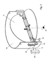
- FIG. 1 an embodiment of the air cleaner unit 1 according to the invention is shown.
- This embodiment of the air cleaner unit 1 comprises an air guide unit 10, a frame 17, a grid 15 and an odor filter 16, of which in the FIG. 1 only the receiving device is shown in the form of a scaffold. The filter material was used for better visibility in the FIG. 1 spared.
- the electronics housing 18 the electronics of the air cleaner unit 1
- a transformer 181 and a switch 182 is provided in the electronics housing 18, the electronics of the air cleaner unit 1, a transformer 181 and a switch 182 is provided.
- Via a distribution strip 183 which in the FIG. 1 is provided outside the electronics housing 18, the air cleaner unit 1 can be supplied with power.
- the frame 17 has a lid 170 and a lid 170 opposite the bottom 171.
- a passage opening 1710 is provided in the bottom 171.
- the lid 170 and the bottom 171 of the frame 17 are connected to each other via vertically extending webs on the back. At the back of the frame 17 this is closed by a separate cover plate 172.
- the grid 15 has the shape of a U-shaped channel. Wherein the two legs of the channel form the sides of the air treatment room 100 inside the air purification unit 1 and the base of the U-shaped channel forms the front side.
- the odor filter 16 has a shape corresponding to that of the grid 15 and surrounds this.
- an air guide unit 10 is provided inside the air cleaner unit 1, which is the air treatment room 100.
- the air guide unit 10 consists of an interface 103, a tubular element 102 and a support member 101.
- the interface 103 is configured in the illustrated embodiment as a pipe socket.
- the interface 103 may be placed on the passage opening 1710 in the bottom 171 of the frame 17 or passed therethrough.
- the interface 103 is connected to a tubular element 102.
- the interface 103 is, for example, inserted into the pipe element 102 from below or otherwise connected thereto and locked thereto.
- an additional element in the form of a flap 13 is provided in the tubular element 102.
- the flap 13 is in the illustrated embodiment, a two-part flap 13, which can close the entire cross section of the tubular element 102.
- the two parts of the flap 13 can be pivoted independently of one another with respect to an axis of rotation, which lies in the diameter of the tubular element 102, and thus release the cross-section of the tubular element 102 at least partially for an air flow.
- a carrier element 101 is arranged in the form of a frame.
- the support member 101 consists of a lower ring 1011 and an upper ring 1010.
- the lower ring is connected to the top of the tube member 102 and locked thereto.
- the two rings 1010 and 1011 each have six fastening devices 104, 105 in the illustrated embodiment.
- a corner of a functional element 11 is accommodated.
- the functional elements 11 in the embodiment shown represent plate-shaped electrodes. In the illustrated embodiment, three electrodes 11 are provided and held between the upper ring 1010 and the lower ring 1011 of the support member 101.
- the upper ring 1010 may abut or be attached to the underside of the lid 170 of the frame 13.
- the held between the rings 1010 and 1011 of the frame 101 electrodes 11 are aligned parallel to each other and extend vertically.
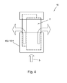
- An airflow, like in FIG. 4 is shown schematically, via the interface 103 and the tube member 102 in the air guide unit 10 is directed vertically upward, will thus flow past the surfaces of the electrodes 11 and thus can be excellently freed from odors.
- FIG. 2 a detail view of the tubular element 102 is shown with flap 13 provided therein.
- the tube element 102 on the outside thereof has a fastening device 106 for a sensor 12.
- the sensor 12 which may represent a Hall sensor, for example, is provided on a sensor housing 120, which can be introduced and held in the fastening device 106.
- the fastening device 106 for the sensor 12 or the sensor housing 120 in the illustrated embodiment represents a rail which extends vertically on the outside of the tubular element 102.
- a passage for the region of the sensor housing 120 is provided, on which the sensor 12 is provided.
- a fastening device (not shown) for the flap 13 is provided, which may be a passage in the wall of the tubular element 102.
- the two parts of the flap 13, which in the embodiment shown represents a two-part flap 13, are held in the position by means of a spring 20, in which they close the cross-section of the tube element 102 and thus of the air guiding unit 10.
- a magnet 19 is shown, which may be provided on the flap 13 and on the thus the position of the flap 13 can be determined by the sensor.
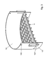
- FIG. 3 is the part of the air guide unit 10 from FIG. 2 shown, wherein the flap 13 is not shown.
- an engagement grid 14 is provided as a further additional element.
- the mesh grille 14 is also referred to as a mesh guard.
- the axis of the flap 13 is shown, which may be provided on the engagement grid 14 additionally or alternatively to a mounting on the wall of the tubular element 102.
- the engagement grid 14 is in the embodiment shown on the top of the interface 103, which may also be referred to as a suction port on.
- Locking devices 1020 and 1201 are further shown.
- the tube member 102 can be connected to the interface 103 and locked thereto.
- the lower ring of the carrier element 101 is connected to the tubular element 102 and locked thereto.
- an air flow S which enters from below into the air cleaner unit 1 and in particular via the interface 103 in the air guide unit 10, over the distance between the rings 1010, 1011 of the support member 101 exit to the sides and on the in FIG. 1 shown grid 15 and the odor filter 16 are discharged to the sides to the environment of the air cleaner unit 1.
- an air guide unit which is also referred to as a unit for air guidance, created in which at least one further functional feature is integrated in the same component.
- This multifunction unit can consist of several components if more than one additional feature is present. Additional functions can be ensured in a simple manner, for example via clip-on additional elements, which can also be referred to as small parts.
- the air guide unit according to the invention is used for the targeted guidance of air in and in the air treatment room and in particular in the reaction space.
- the reaction space designates the space in which the energy is provided for the treatment of the air.
- the air guidance can thus be carried out, for example, specifically along the electrodes to produce a DBE plasma.
- the invention is not limited to air cleaner units for active odor removal, for example by means of plasma, catalysts or UV, but also relates to the air duct, for example in an activated carbon filter unit.
- the activated carbon filter can therefore be uniformly flowed and loaded in the present invention.
- Another air guide unit after the air cleaner unit is possible according to the invention. Such additional air flow can ensure the outflow of air particularly resistant and quiet. In all cases, in the present invention, the optimization of flow and odor removal in the foreground.
- the air guide unit according to the invention is designed so that it has at least one other function or can perform. Particularly preferably, at least a part of the air guide unit constitutes a carrier element or a plurality of carrier elements for the electrodes for plasma generation.
- This support element, these support elements or additional pipe elements can also be used, for example, for filters, catalyst material and / or sensors. Since the functional elements, such as electrodes, filters, catalyst material and / or additional elements, such as sensors, are held on the carrier elements or pipe elements, these are also referred to as a holding device.
- the electrodes to be flown can be optimally fixed in relation to the air flow.
- the electrical insulation (sufficient creepage distances or the like) can be ensured.
- a further integrated carrier element or tube element of the air-guiding unit may for example contain a sensor or it may be fastened to the carrier element or tube element.
- the sensor may represent, for example, an ozone sensor.
- the entire air guide unit may be designed as a supporting structure of the air cleaner unit.
- Other additional functions which may also make additional plug-in components possible, are conceivable.
- an intervention protection can be integrated into the air cleaner unit. This can be done for example by an attachable, the electrodes encompassing grid.
- the air guide unit can also be a flap, possibly integrated via a clip-pipe element.
- the air guide unit can be designed so that, for example, cables are guided in a targeted manner to sensors or electrodes. This allows high-voltage cables to be physically separated from low-voltage cables.
- the leadership of the cable can be realized for example by suitable fastening devices on one or more of the support elements or pipe elements of the air guide unit.
- a housing for electronic components can according to the invention, for example, connect to the air guide unit and be completed by means of a clip-on lid.
- a specially designed interface to the extractor hood of the extractor device in or with which the air cleaner unit is to be operated is also within the scope of the invention. This ensures that only extractors approved for the combination can be combined with the air purifier unit. These special extractor hoods can be tested for function and safety with the air cleaner unit, increasing user convenience. In this case, the counterpart to the cooker hood must be designed accordingly.
- the interface can for example be designed so that the air guide unit is equipped with a sensor that detects a mounted in the connection part, which may be, for example, an exhaust pipe, the hood mounted magnet. When combined with an extractor not approved for combination with the air cleaner unit, the air cleaner unit receives no signal from the hood and can not be operated if the electronics are designed accordingly.
- a mechanical latching or coupling to an electromagnetic switch between the extractor hood and the air cleaner unit is conceivable.
- the air cleaner unit according to the invention combines the optimization of the flow conditions with the function of support elements in which functional elements, for example for air purification, in particular filters or electrodes, are optimized for their functions. As a result, the delivery volume, the reduction of noise and odor removal can be optimized. Other functions of the air cleaner unit, which can be realized by additional elements, for example, serve the safety of the user.
- the present invention has a number of advantages.
- an air cleaner unit for use in combination with extractor hoods is provided, in which the air flow in a certain way in the air treatment room, and in particular in the reaction chamber, can be performed.
- other functions can be linked to the air cleaner unit, such as the inclusion of certain components, which are also referred to as functional elements and, for example, electrodes for generating of a DBE plasma.
- the air cleaner unit according to the invention it is possible by the air cleaner unit according to the invention to provide a defined interface to the hood.
Landscapes
- Engineering & Computer Science (AREA)
- Chemical & Material Sciences (AREA)
- Combustion & Propulsion (AREA)
- Mechanical Engineering (AREA)
- General Engineering & Computer Science (AREA)
- Filtering Of Dispersed Particles In Gases (AREA)
- Disinfection, Sterilisation Or Deodorisation Of Air (AREA)
Applications Claiming Priority (1)
| Application Number | Priority Date | Filing Date | Title |
|---|---|---|---|
| DE102012215028.5A DE102012215028A1 (de) | 2012-08-23 | 2012-08-23 | Luftreinigereinheit einer Dunstabzugsvorrichtung |
Publications (3)
| Publication Number | Publication Date |
|---|---|
| EP2700882A2 true EP2700882A2 (fr) | 2014-02-26 |
| EP2700882A3 EP2700882A3 (fr) | 2017-07-12 |
| EP2700882B1 EP2700882B1 (fr) | 2020-07-29 |
Family
ID=48985983
Family Applications (1)
| Application Number | Title | Priority Date | Filing Date |
|---|---|---|---|
| EP13179949.6A Active EP2700882B1 (fr) | 2012-08-23 | 2013-08-09 | Purificateur d'air pour une hotte d'aspiration |
Country Status (2)
| Country | Link |
|---|---|
| EP (1) | EP2700882B1 (fr) |
| DE (1) | DE102012215028A1 (fr) |
Cited By (1)
| Publication number | Priority date | Publication date | Assignee | Title |
|---|---|---|---|---|
| WO2020109489A1 (fr) * | 2018-11-30 | 2020-06-04 | BSH Hausgeräte GmbH | Module filtrant électrostatique pour épurateur d'air et épurateur d'air |
Families Citing this family (1)
| Publication number | Priority date | Publication date | Assignee | Title |
|---|---|---|---|---|
| CN111649369A (zh) * | 2020-06-18 | 2020-09-11 | 南京腾飞不锈钢厨房设备有限公司 | 一种低噪音厨房油烟净化系统 |
Family Cites Families (7)
| Publication number | Priority date | Publication date | Assignee | Title |
|---|---|---|---|---|
| DE3404004A1 (de) * | 1983-04-19 | 1984-10-25 | Friedrich 8000 München Bürcher | Ab- und zuluftvorrichtung fuer eine kochstelle |
| DE10113013A1 (de) * | 2001-03-17 | 2002-10-02 | Guenter Schulte | Anordnung umfassend eine Dunstabzugshaube |
| DE10118881A1 (de) * | 2001-04-18 | 2002-11-07 | Sino Gmbh | Dunstabzugshaubensystem |
| EP1765044A1 (fr) * | 2005-09-16 | 2007-03-21 | Max-Planck-Gesellschaft zur Förderung der Wissenschaften e.V. | Source plasma |
| JP2008049298A (ja) * | 2006-08-25 | 2008-03-06 | Asuka Medical:Kk | 揮発性有機物質含有ガス浄化カートリッジ、該カートリッジを用いた屋内用の廃ガス浄化装置、廃ガスの浄化システム及び廃ガスの浄化方法 |
| DE102008054775A1 (de) * | 2008-12-16 | 2010-06-17 | BSH Bosch und Siemens Hausgeräte GmbH | Luftaufbereitungsvorrichtung und Verfahren zum Detektieren eines Filterelementes in einer Luftaufbereitungsvorrichtung |
| EP2223704A1 (fr) * | 2009-02-17 | 2010-09-01 | Max-Planck-Gesellschaft zur Förderung der Wissenschaften e.V. | Dispositif de traitement d'une partie du corps d'un patient avec un plasma non thermique |
-
2012
- 2012-08-23 DE DE102012215028.5A patent/DE102012215028A1/de not_active Withdrawn
-
2013
- 2013-08-09 EP EP13179949.6A patent/EP2700882B1/fr active Active
Non-Patent Citations (1)
| Title |
|---|
| None |
Cited By (1)
| Publication number | Priority date | Publication date | Assignee | Title |
|---|---|---|---|---|
| WO2020109489A1 (fr) * | 2018-11-30 | 2020-06-04 | BSH Hausgeräte GmbH | Module filtrant électrostatique pour épurateur d'air et épurateur d'air |
Also Published As
| Publication number | Publication date |
|---|---|
| EP2700882A3 (fr) | 2017-07-12 |
| EP2700882B1 (fr) | 2020-07-29 |
| DE102012215028A1 (de) | 2014-02-27 |
Similar Documents
| Publication | Publication Date | Title |
|---|---|---|
| DE102017217853B4 (de) | Kochfeldsystem mit Dunstabzugsvorrichtung | |
| EP3338028B1 (fr) | Appareil combiné avec plaque de cuisson et dispositif d'evacuation des fumées | |
| EP3475622B1 (fr) | Système de ventilation à courant descendant avec un insert | |
| EP2570735B1 (fr) | Système de cheminée de ventilation et procédé de fonctionnement d'un tel système | |
| WO2017029134A1 (fr) | Appareil combiné comprenant une plaque de cuisson et un dispositif d'aspiration des émanations | |
| DE20117490U1 (de) | Luftabsaugvorrichtung für einen Arbeitsplatz | |
| EP3133349B1 (fr) | Unité combinée comprenant une zone de cuisson et un dispositif d'aspiration de fumée comprenant une unité de filtration | |
| EP3136004A1 (fr) | Appareil combiné comprenant une plaque de cuisson et un dispositif d'aspiration de fumées | |
| WO2020152288A1 (fr) | Dispositif d'évacuation des émanations pour plaque de cuisson et appareil combiné | |
| WO2019081271A1 (fr) | Appareil combiné comprenant un dispositif d'aspiration des fumées et une table de cuisson | |
| EP2199688B1 (fr) | Dispositif de traitement de l'air et procédé d'utilisation de ce dispositif | |
| EP2700882A2 (fr) | Purificateur d'air d'un dispositif d'aspiration de vapeur | |
| WO2009101099A1 (fr) | Système d’aspiration d'émanations à boîtier de filtre séparé | |
| DE102020213310A1 (de) | Lüftereinrichtung zum Fördern von Luft | |
| EP2518412A2 (fr) | Installation dýaération | |
| WO2019096701A1 (fr) | Dispositif d'aspiration des fumées pour une table de cuisson et meuble de cuisine doté d'un dispositif d'aspiration des fumées | |
| DE102019220266B4 (de) | Lüftereinrichtung zum Fördern von Luft | |
| EP3653940B1 (fr) | Hotte aspirante | |
| EP2554915B1 (fr) | Hotte aspirante avec support de filtre et élément filtrant d'odeurs | |
| DE10015745A1 (de) | Dunstabzugsvorrichtung | |
| EP2615383B1 (fr) | Hotte aspirante | |
| EP2736396B1 (fr) | Aspirateur | |
| EP3701193B1 (fr) | Appareil combiné comprenant un dispositif d'aspiration de fumées et une plaque de cuisson | |
| EP4325125A2 (fr) | Dispositif d'aspiration de fumées doté d'au moins un adaptateur d'air ambiant, système de ventilation de plafond et procédé de fonctionnement | |
| BE1030782A1 (de) | Dunstabzugeinrichtung mit wenigstens einem Umluftadapter, Deckenlüftersystem und Verfahren zum Betreiben |
Legal Events
| Date | Code | Title | Description |
|---|---|---|---|
| PUAI | Public reference made under article 153(3) epc to a published international application that has entered the european phase |
Free format text: ORIGINAL CODE: 0009012 |
|
| AK | Designated contracting states |
Kind code of ref document: A2 Designated state(s): AL AT BE BG CH CY CZ DE DK EE ES FI FR GB GR HR HU IE IS IT LI LT LU LV MC MK MT NL NO PL PT RO RS SE SI SK SM TR |
|
| AX | Request for extension of the european patent |
Extension state: BA ME |
|
| RAP1 | Party data changed (applicant data changed or rights of an application transferred) |
Owner name: BSH HAUSGERAETE GMBH |
|
| PUAL | Search report despatched |
Free format text: ORIGINAL CODE: 0009013 |
|
| AK | Designated contracting states |
Kind code of ref document: A3 Designated state(s): AL AT BE BG CH CY CZ DE DK EE ES FI FR GB GR HR HU IE IS IT LI LT LU LV MC MK MT NL NO PL PT RO RS SE SI SK SM TR |
|
| AX | Request for extension of the european patent |
Extension state: BA ME |
|
| RIC1 | Information provided on ipc code assigned before grant |
Ipc: F24C 15/20 20060101AFI20170607BHEP |
|
| STAA | Information on the status of an ep patent application or granted ep patent |
Free format text: STATUS: REQUEST FOR EXAMINATION WAS MADE |
|
| 17P | Request for examination filed |
Effective date: 20180112 |
|
| RBV | Designated contracting states (corrected) |
Designated state(s): AL AT BE BG CH CY CZ DE DK EE ES FI FR GB GR HR HU IE IS IT LI LT LU LV MC MK MT NL NO PL PT RO RS SE SI SK SM TR |
|
| STAA | Information on the status of an ep patent application or granted ep patent |
Free format text: STATUS: EXAMINATION IS IN PROGRESS |
|
| 17Q | First examination report despatched |
Effective date: 20180329 |
|
| GRAP | Despatch of communication of intention to grant a patent |
Free format text: ORIGINAL CODE: EPIDOSNIGR1 |
|
| STAA | Information on the status of an ep patent application or granted ep patent |
Free format text: STATUS: GRANT OF PATENT IS INTENDED |
|
| RIC1 | Information provided on ipc code assigned before grant |
Ipc: F24C 15/20 20060101AFI20200204BHEP Ipc: B03C 3/86 20060101ALI20200204BHEP Ipc: B03C 3/08 20060101ALI20200204BHEP Ipc: B03C 3/47 20060101ALI20200204BHEP |
|
| INTG | Intention to grant announced |
Effective date: 20200311 |
|
| GRAS | Grant fee paid |
Free format text: ORIGINAL CODE: EPIDOSNIGR3 |
|
| GRAA | (expected) grant |
Free format text: ORIGINAL CODE: 0009210 |
|
| STAA | Information on the status of an ep patent application or granted ep patent |
Free format text: STATUS: THE PATENT HAS BEEN GRANTED |
|
| AK | Designated contracting states |
Kind code of ref document: B1 Designated state(s): AL AT BE BG CH CY CZ DE DK EE ES FI FR GB GR HR HU IE IS IT LI LT LU LV MC MK MT NL NO PL PT RO RS SE SI SK SM TR |
|
| REG | Reference to a national code |
Ref country code: GB Ref legal event code: FG4D Free format text: NOT ENGLISH |
|
| REG | Reference to a national code |
Ref country code: CH Ref legal event code: EP |
|
| REG | Reference to a national code |
Ref country code: AT Ref legal event code: REF Ref document number: 1296242 Country of ref document: AT Kind code of ref document: T Effective date: 20200815 |
|
| REG | Reference to a national code |
Ref country code: IE Ref legal event code: FG4D Free format text: LANGUAGE OF EP DOCUMENT: GERMAN |
|
| REG | Reference to a national code |
Ref country code: DE Ref legal event code: R096 Ref document number: 502013014958 Country of ref document: DE |
|
| REG | Reference to a national code |
Ref country code: NL Ref legal event code: FP |
|
| REG | Reference to a national code |
Ref country code: LT Ref legal event code: MG4D |
|
| PG25 | Lapsed in a contracting state [announced via postgrant information from national office to epo] |
Ref country code: HR Free format text: LAPSE BECAUSE OF FAILURE TO SUBMIT A TRANSLATION OF THE DESCRIPTION OR TO PAY THE FEE WITHIN THE PRESCRIBED TIME-LIMIT Effective date: 20200729 Ref country code: PT Free format text: LAPSE BECAUSE OF FAILURE TO SUBMIT A TRANSLATION OF THE DESCRIPTION OR TO PAY THE FEE WITHIN THE PRESCRIBED TIME-LIMIT Effective date: 20201130 Ref country code: SE Free format text: LAPSE BECAUSE OF FAILURE TO SUBMIT A TRANSLATION OF THE DESCRIPTION OR TO PAY THE FEE WITHIN THE PRESCRIBED TIME-LIMIT Effective date: 20200729 Ref country code: GR Free format text: LAPSE BECAUSE OF FAILURE TO SUBMIT A TRANSLATION OF THE DESCRIPTION OR TO PAY THE FEE WITHIN THE PRESCRIBED TIME-LIMIT Effective date: 20201030 Ref country code: FI Free format text: LAPSE BECAUSE OF FAILURE TO SUBMIT A TRANSLATION OF THE DESCRIPTION OR TO PAY THE FEE WITHIN THE PRESCRIBED TIME-LIMIT Effective date: 20200729 Ref country code: LT Free format text: LAPSE BECAUSE OF FAILURE TO SUBMIT A TRANSLATION OF THE DESCRIPTION OR TO PAY THE FEE WITHIN THE PRESCRIBED TIME-LIMIT Effective date: 20200729 Ref country code: BG Free format text: LAPSE BECAUSE OF FAILURE TO SUBMIT A TRANSLATION OF THE DESCRIPTION OR TO PAY THE FEE WITHIN THE PRESCRIBED TIME-LIMIT Effective date: 20201029 Ref country code: NO Free format text: LAPSE BECAUSE OF FAILURE TO SUBMIT A TRANSLATION OF THE DESCRIPTION OR TO PAY THE FEE WITHIN THE PRESCRIBED TIME-LIMIT Effective date: 20201029 Ref country code: ES Free format text: LAPSE BECAUSE OF FAILURE TO SUBMIT A TRANSLATION OF THE DESCRIPTION OR TO PAY THE FEE WITHIN THE PRESCRIBED TIME-LIMIT Effective date: 20200729 |
|
| PG25 | Lapsed in a contracting state [announced via postgrant information from national office to epo] |
Ref country code: IS Free format text: LAPSE BECAUSE OF FAILURE TO SUBMIT A TRANSLATION OF THE DESCRIPTION OR TO PAY THE FEE WITHIN THE PRESCRIBED TIME-LIMIT Effective date: 20201129 Ref country code: RS Free format text: LAPSE BECAUSE OF FAILURE TO SUBMIT A TRANSLATION OF THE DESCRIPTION OR TO PAY THE FEE WITHIN THE PRESCRIBED TIME-LIMIT Effective date: 20200729 Ref country code: PL Free format text: LAPSE BECAUSE OF FAILURE TO SUBMIT A TRANSLATION OF THE DESCRIPTION OR TO PAY THE FEE WITHIN THE PRESCRIBED TIME-LIMIT Effective date: 20200729 Ref country code: LV Free format text: LAPSE BECAUSE OF FAILURE TO SUBMIT A TRANSLATION OF THE DESCRIPTION OR TO PAY THE FEE WITHIN THE PRESCRIBED TIME-LIMIT Effective date: 20200729 |
|
| REG | Reference to a national code |
Ref country code: CH Ref legal event code: PL |
|
| PG25 | Lapsed in a contracting state [announced via postgrant information from national office to epo] |
Ref country code: RO Free format text: LAPSE BECAUSE OF FAILURE TO SUBMIT A TRANSLATION OF THE DESCRIPTION OR TO PAY THE FEE WITHIN THE PRESCRIBED TIME-LIMIT Effective date: 20200729 Ref country code: SM Free format text: LAPSE BECAUSE OF FAILURE TO SUBMIT A TRANSLATION OF THE DESCRIPTION OR TO PAY THE FEE WITHIN THE PRESCRIBED TIME-LIMIT Effective date: 20200729 Ref country code: LU Free format text: LAPSE BECAUSE OF NON-PAYMENT OF DUE FEES Effective date: 20200809 Ref country code: MC Free format text: LAPSE BECAUSE OF FAILURE TO SUBMIT A TRANSLATION OF THE DESCRIPTION OR TO PAY THE FEE WITHIN THE PRESCRIBED TIME-LIMIT Effective date: 20200729 Ref country code: LI Free format text: LAPSE BECAUSE OF NON-PAYMENT OF DUE FEES Effective date: 20200831 Ref country code: DK Free format text: LAPSE BECAUSE OF FAILURE TO SUBMIT A TRANSLATION OF THE DESCRIPTION OR TO PAY THE FEE WITHIN THE PRESCRIBED TIME-LIMIT Effective date: 20200729 Ref country code: CH Free format text: LAPSE BECAUSE OF NON-PAYMENT OF DUE FEES Effective date: 20200831 Ref country code: EE Free format text: LAPSE BECAUSE OF FAILURE TO SUBMIT A TRANSLATION OF THE DESCRIPTION OR TO PAY THE FEE WITHIN THE PRESCRIBED TIME-LIMIT Effective date: 20200729 Ref country code: CZ Free format text: LAPSE BECAUSE OF FAILURE TO SUBMIT A TRANSLATION OF THE DESCRIPTION OR TO PAY THE FEE WITHIN THE PRESCRIBED TIME-LIMIT Effective date: 20200729 |
|
| REG | Reference to a national code |
Ref country code: DE Ref legal event code: R097 Ref document number: 502013014958 Country of ref document: DE |
|
| REG | Reference to a national code |
Ref country code: BE Ref legal event code: MM Effective date: 20200831 |
|
| PG25 | Lapsed in a contracting state [announced via postgrant information from national office to epo] |
Ref country code: AL Free format text: LAPSE BECAUSE OF FAILURE TO SUBMIT A TRANSLATION OF THE DESCRIPTION OR TO PAY THE FEE WITHIN THE PRESCRIBED TIME-LIMIT Effective date: 20200729 |
|
| PLBE | No opposition filed within time limit |
Free format text: ORIGINAL CODE: 0009261 |
|
| STAA | Information on the status of an ep patent application or granted ep patent |
Free format text: STATUS: NO OPPOSITION FILED WITHIN TIME LIMIT |
|
| GBPC | Gb: european patent ceased through non-payment of renewal fee |
Effective date: 20201029 |
|
| PG25 | Lapsed in a contracting state [announced via postgrant information from national office to epo] |
Ref country code: SK Free format text: LAPSE BECAUSE OF FAILURE TO SUBMIT A TRANSLATION OF THE DESCRIPTION OR TO PAY THE FEE WITHIN THE PRESCRIBED TIME-LIMIT Effective date: 20200729 |
|
| 26N | No opposition filed |
Effective date: 20210430 |
|
| PG25 | Lapsed in a contracting state [announced via postgrant information from national office to epo] |
Ref country code: FR Free format text: LAPSE BECAUSE OF NON-PAYMENT OF DUE FEES Effective date: 20200929 |
|
| PG25 | Lapsed in a contracting state [announced via postgrant information from national office to epo] |
Ref country code: IE Free format text: LAPSE BECAUSE OF NON-PAYMENT OF DUE FEES Effective date: 20200809 Ref country code: GB Free format text: LAPSE BECAUSE OF NON-PAYMENT OF DUE FEES Effective date: 20201029 Ref country code: SI Free format text: LAPSE BECAUSE OF FAILURE TO SUBMIT A TRANSLATION OF THE DESCRIPTION OR TO PAY THE FEE WITHIN THE PRESCRIBED TIME-LIMIT Effective date: 20200729 Ref country code: BE Free format text: LAPSE BECAUSE OF NON-PAYMENT OF DUE FEES Effective date: 20200831 |
|
| REG | Reference to a national code |
Ref country code: AT Ref legal event code: MM01 Ref document number: 1296242 Country of ref document: AT Kind code of ref document: T Effective date: 20200809 |
|
| PG25 | Lapsed in a contracting state [announced via postgrant information from national office to epo] |
Ref country code: AT Free format text: LAPSE BECAUSE OF NON-PAYMENT OF DUE FEES Effective date: 20200809 |
|
| PG25 | Lapsed in a contracting state [announced via postgrant information from national office to epo] |
Ref country code: TR Free format text: LAPSE BECAUSE OF FAILURE TO SUBMIT A TRANSLATION OF THE DESCRIPTION OR TO PAY THE FEE WITHIN THE PRESCRIBED TIME-LIMIT Effective date: 20200729 Ref country code: MT Free format text: LAPSE BECAUSE OF FAILURE TO SUBMIT A TRANSLATION OF THE DESCRIPTION OR TO PAY THE FEE WITHIN THE PRESCRIBED TIME-LIMIT Effective date: 20200729 Ref country code: CY Free format text: LAPSE BECAUSE OF FAILURE TO SUBMIT A TRANSLATION OF THE DESCRIPTION OR TO PAY THE FEE WITHIN THE PRESCRIBED TIME-LIMIT Effective date: 20200729 |
|
| PG25 | Lapsed in a contracting state [announced via postgrant information from national office to epo] |
Ref country code: MK Free format text: LAPSE BECAUSE OF FAILURE TO SUBMIT A TRANSLATION OF THE DESCRIPTION OR TO PAY THE FEE WITHIN THE PRESCRIBED TIME-LIMIT Effective date: 20200729 |
|
| PGFP | Annual fee paid to national office [announced via postgrant information from national office to epo] |
Ref country code: DE Payment date: 20220831 Year of fee payment: 10 |
|
| REG | Reference to a national code |
Ref country code: DE Ref legal event code: R084 Ref document number: 502013014958 Country of ref document: DE |
|
| PGFP | Annual fee paid to national office [announced via postgrant information from national office to epo] |
Ref country code: NL Payment date: 20230823 Year of fee payment: 11 |
|
| PGFP | Annual fee paid to national office [announced via postgrant information from national office to epo] |
Ref country code: IT Payment date: 20230831 Year of fee payment: 11 |
|
| REG | Reference to a national code |
Ref country code: DE Ref legal event code: R119 Ref document number: 502013014958 Country of ref document: DE |
|
| PG25 | Lapsed in a contracting state [announced via postgrant information from national office to epo] |
Ref country code: DE Free format text: LAPSE BECAUSE OF NON-PAYMENT OF DUE FEES Effective date: 20240301 |