EP2700345A2 - Staubsauger mit Bedien- und Anzeigeelementen - Google Patents
Staubsauger mit Bedien- und Anzeigeelementen Download PDFInfo
- Publication number
- EP2700345A2 EP2700345A2 EP13401082.6A EP13401082A EP2700345A2 EP 2700345 A2 EP2700345 A2 EP 2700345A2 EP 13401082 A EP13401082 A EP 13401082A EP 2700345 A2 EP2700345 A2 EP 2700345A2
- Authority
- EP
- European Patent Office
- Prior art keywords
- vacuum cleaner
- projection
- light source
- display elements
- projection unit
- Prior art date
- Legal status (The legal status is an assumption and is not a legal conclusion. Google has not performed a legal analysis and makes no representation as to the accuracy of the status listed.)
- Granted
Links
Images

Classifications
-
- A—HUMAN NECESSITIES
- A47—FURNITURE; DOMESTIC ARTICLES OR APPLIANCES; COFFEE MILLS; SPICE MILLS; SUCTION CLEANERS IN GENERAL
- A47L—DOMESTIC WASHING OR CLEANING; SUCTION CLEANERS IN GENERAL
- A47L9/00—Details or accessories of suction cleaners, e.g. mechanical means for controlling the suction or for effecting pulsating action; Storing devices specially adapted to suction cleaners or parts thereof; Carrying-vehicles specially adapted for suction cleaners
- A47L9/28—Installation of the electric equipment, e.g. adaptation or attachment to the suction cleaner; Controlling suction cleaners by electric means
- A47L9/30—Arrangement of illuminating devices
-
- A—HUMAN NECESSITIES
- A47—FURNITURE; DOMESTIC ARTICLES OR APPLIANCES; COFFEE MILLS; SPICE MILLS; SUCTION CLEANERS IN GENERAL
- A47L—DOMESTIC WASHING OR CLEANING; SUCTION CLEANERS IN GENERAL
- A47L9/00—Details or accessories of suction cleaners, e.g. mechanical means for controlling the suction or for effecting pulsating action; Storing devices specially adapted to suction cleaners or parts thereof; Carrying-vehicles specially adapted for suction cleaners
- A47L9/28—Installation of the electric equipment, e.g. adaptation or attachment to the suction cleaner; Controlling suction cleaners by electric means
- A47L9/2805—Parameters or conditions being sensed
-
- A—HUMAN NECESSITIES
- A47—FURNITURE; DOMESTIC ARTICLES OR APPLIANCES; COFFEE MILLS; SPICE MILLS; SUCTION CLEANERS IN GENERAL
- A47L—DOMESTIC WASHING OR CLEANING; SUCTION CLEANERS IN GENERAL
- A47L9/00—Details or accessories of suction cleaners, e.g. mechanical means for controlling the suction or for effecting pulsating action; Storing devices specially adapted to suction cleaners or parts thereof; Carrying-vehicles specially adapted for suction cleaners
- A47L9/28—Installation of the electric equipment, e.g. adaptation or attachment to the suction cleaner; Controlling suction cleaners by electric means
- A47L9/2857—User input or output elements for control, e.g. buttons, switches or displays
-
- A—HUMAN NECESSITIES
- A47—FURNITURE; DOMESTIC ARTICLES OR APPLIANCES; COFFEE MILLS; SPICE MILLS; SUCTION CLEANERS IN GENERAL
- A47L—DOMESTIC WASHING OR CLEANING; SUCTION CLEANERS IN GENERAL
- A47L9/00—Details or accessories of suction cleaners, e.g. mechanical means for controlling the suction or for effecting pulsating action; Storing devices specially adapted to suction cleaners or parts thereof; Carrying-vehicles specially adapted for suction cleaners
- A47L9/32—Handles
- A47L9/327—Handles for suction cleaners with hose between nozzle and casing
Definitions
- the invention relates to a vacuum cleaner with with operating and display elements for the operation of the vacuum cleaner and the display of information.
- vacuum cleaners are provided with mechanical buttons or switches for the operation of the vacuum cleaner.
- display elements such as displays for the display of the vacuum cleaner performance or the level of the vacuum cleaner bag may be provided.
- the DE 199 18 072 A1 shows and describes a process control with control and display elements for the operation of the process and the display of information, comprising a projection unit for projection of the control and display element on a projection screen, a light source for radiation and a camera for receiving reflected beams of the light source Detection of operation of the controls on the screen.
- the invention thus raises the problem of simplifying the control and display elements, thereby facilitating the operation of the vacuum cleaner and to allow a better display of information such as the level of the filter and the suction power.
- a vacuum cleaner according to the invention has a projection unit for projecting the operating and display elements onto a projection surface, a light source for radiation in the non-visible region and a camera for recording reflected rays of the light source for detecting an operation of the control elements on the projection surface.
- a projection unit that projects an image onto a projection screen
- a flexible design of operating and display elements is made possible.
- the operating gestures of an operator can be detected on the projection surface, whereby a simple operation of the virtual projection screen is made possible.
- a light source in the non-visible area, in particular in the infrared range, and a camera for receiving the reflected rays from a gesture object such as a finger on the projected controls such as the keys of a keyboard. From the reflection of the light beam, the location of the gesture object on the control element and thus the desired function is calculated. In particular, wiping movements can be detected, as they are known for example from the operation of smartphones.
- the solution according to the invention has the overall advantage that it requires a small space, consists of simple optoelectronic components and is inexpensive. It opens up new design possibilities for the design of a vacuum cleaner.
- the projection unit may comprise a laser or one or more LEDs (Light Emitting Diodes) with which e.g. a control on a projection screen can be projected.
- LEDs Light Emitting Diodes
- the laser itself requires only a small amount of space.
- the projection unit is housed in the upper handle of the dust tube of the vacuum cleaner.
- the projection unit is housed in the upper handle of the dust tube of the vacuum cleaner.
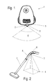
- a vacuum cleaner 1 is shown with a projection unit 2 on the back 3 of the vacuum cleaner 1.
- a projection laser or LEDs By means of a projection laser or LEDs, a projection onto a projection surface 4 takes place, which is shown here with dashed lines as a radiation cone.
- the image of controls or display elements or any other information can be displayed.
- the operator's gestures can then be converted into control signals ,
- the gestures may also be swiping, as they are known for the operation of smartphones act.
- the electronic camera and the light source 5 are likewise distinguished by a detection or illumination cone, wherein the aperture angle is in each case selected such that it can capture at least the area of the projected image 4.
- any surfaces can be used as projection surfaces 4, since the usually required arrangement of the projector orthogonal to the projection surface is not required.
- the projection can be done behind, beside, in front of or on the vacuum cleaner.
- General projection contents refer to the operating condition of the vacuum cleaner. It is possible to display the power and / or power adjustment controls. It is particularly advantageous to recommend which floor coverings should be vacuumed in which capacity level. Furthermore, an automatic level can also be displayed.
- a filter change display can be done, in which case additional information on the position of the opening button for the dust chamber or a filter change video can be shown. It is also possible to display faults and errors and to display the customer service telephone number.
- a user manual can be displayed or tips for the care of floor coverings, hints for purchasable accessories as well as an overview of technical data of the vacuum cleaner can be displayed.
- the projection unit 2 can be used for illuminating a floor surface to be cleaned, for example in the region of the suction nozzles.
- An advantageous embodiment is the projection of a handle 6 of a dust pipe 7 of the vacuum cleaner 1 out, as in Fig. 2 is shown.
- the projection unit 2 is located behind the front suction attachment 8, since optimal operation during the suction process is provided here.
- the projection surface 4 is advantageously the bottom itself, so that the operator can be displayed with the vacuuming important and interesting additional information.
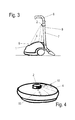
- FIG. 3 illustrates a further advantage of housing the projection unit 2 in the handle 6 of the suction tube 7 is that when you turn off the suction tube 7 on the back 3 of the vacuum cleaner 1 in a parking position projection on the top 9 of the vacuum cleaner 1 can take place.
- information relating to the filter change is of interest in this position.
- the operator can be informed via a projection on the floor that a filter bag change is required.
- the operator may be required to park the suction tube 7 on the back 3 of the vacuum cleaner 1 for further additional information. If the operator now parks the vacuum cleaner 1 after completion of the suction process, then automatically appears on the top 9 of the vacuum cleaner 1 an indication at which point the vacuum cleaner 1 is to open and how to change the filter bag is.
- additional information on the purchase of filter bags eg by Internet ordering, or the benefits that original filter bags offer, can be displayed. An adaptation of the information content to country-specific requirements is also easily possible.
- Further possible information in a projection on the top 9 of the vacuum cleaner 1 may concern the dust compartment cover, the accessory compartment or the parking position of the dust tube. Or the position of filters or filter bags to be changed is displayed. In addition, further additional information on filter types, reordering or disposal etc. is possible. A further development plans to play film sequences to illustrate the filter change on the projection screen.
- Fig. 4 is also a projection in a self-propelled vacuum cleaner, hereinafter referred to as robotic vacuum cleaner 10, on the surface 11 is possible.
- the robot vacuum cleaner 10 is a technically advanced type of vacuum cleaner, which automatically navigates with the aid of sensors over the floor surface to be sucked. It is conceivable that the entire surface 11 is illuminated or only one segment. It is also conceivable to make the projection unit 2 rotatable, so that alternately different segments serve as the projection surface 4.
- a further development provides for automatic pivoting of the projection surface 4, depending on the position of use of the vacuum cleaner 1. So is in Fig. 5 the position of the projection surface 4 during the suction process shown.
- the projection unit 2 is located on the rear side 3 of the vacuum cleaner 1 and illuminates the floor within the projection surface 4.
- the projection unit 2 In the in Fig. 6 shown parking position, however, a smaller area is illuminated, since the projection unit 2 now occupies a smaller distance from the ground.
- the projection unit 2 is designed such that focusing of the desired projection image always takes place on the desired projection surface 4.
- a further development can provide for the projection unit 2 itself to be pivotably mounted in the different spatial directions, so that different projection surfaces 4 can be illuminated.
- Fig. 7 is another form of a projection display 2 shown.
- a projection screen 12 is additionally provided, which is attached to the handle 6.
- the projection unit 2 is also located on the handle 6 and illuminates the projection screen 12.
- the proximity to the handle 6 is a simple operation via a gesture control by an operator possible. The operator does not have to bend down to the vacuum cleaner 1, to serve this.
- various information from the projection screen 12 can be read well, since the projection surface 4 is sufficiently large and thus good readability is given.
- the invention thus makes it possible, in particular, to create a new device design, since the operating and display unit can be brought together.
- a projection of additional information and special functions is very easy.
- a control over gestures such as wiping movements similar to smartphones is conceivable, for example, to regulate the performance of the vacuum cleaner up or down.
- operating habits as increasingly established in other areas, can also be used for the use of vacuum cleaners.
Landscapes
- Engineering & Computer Science (AREA)
- Mechanical Engineering (AREA)
- Electric Vacuum Cleaner (AREA)
- Position Input By Displaying (AREA)
Abstract
Description
- Die Erfindung betrifft einen Staubsauger mit mit Bedien- und Anzeigeelementen für die Bedienung des Staubsaugers und die Anzeige von Informationen.
- Üblicherweise sind Staubsauger mit mechanischen Tasten oder Schaltern versehen für die Bedienung des Staubsaugers. Außerdem können Anzeigeelemente wie Displays für die Anzeige der Staubsaugerleistung oder den Füllstand des Staubsaugerbeutels vorgesehen sein.
- Bei der Gestaltung des Designs eines Staubsaugers muss häufig ein Kompromiss zwischen der Handhabung und dem Bedienkomfort sowie der Gestaltung der Oberflächen und der Anzeige- und Bedienelemente getroffen werden. Zudem werden einige der Bedienelemente nicht von Hand bedient, sondern sind als Tritttasten ausgebildet, die häufig eher schwierig zu bedienen sind. Die Anzeigeelemente für die Staubsaugerleistung, einen erforderlichen Filterwechsel oder mögliche Störungen geben oft nur Basisinformationen wieder und sind zudem sehr klein ausgebildet, so dass die Information schlecht sichtbar ist.
- Darüber hinaus sind mechanische Bedienelemente und elektronische Anzeigeelemente kostenintensiv und können auch während des Einsatzes eines Staubsaugers auch beschädigt werden. Außerdem benötigen diese Bedien- und Anzeigelemente einen gewissen Bauraum im Staubsaugerinnenraum, was sich negativ auf die Baugröße des Staubsaugers auswirkt.
- Die
DE 199 18 072 A1 zeigt und beschreibt eine Prozesssteuerung mit Bedien- und Anzeigeelementen für die Bedienung des Prozesses und die Anzeige von Informationen, aufweisend eine Projektionseinheit zur Projektion der Bedien- und Anzeigeelement auf einer Projektionsfläche, eine Lichtquelle für Strahlung und eine Kamera zur Aufnahme von reflektierten Strahlen der Lichtquelle zur Erkennung einer Bedienung der Bedienelemente auf der Projektionsfläche. - Aus der
DE 195 25 894 A1 ist ein Staubsauger mit einer Projektionseinheit bekannt. In derDE 10 2011 050 357 A1 ist ein selbstständig verfahrbares Reinigungsgerät mit einer Kamera zur Erfassung von Bewegungsmustern eines Benutzers offenbart. - Der Erfindung stellt sich somit das Problem, die Bedien- und Anzeigeelemente zu vereinfachen, dabei die Bedienung des Staubsaugers zu erleichtern und eine bessere Anzeige von Informationen wie z.B. der Füllstand des Filters und die Saugleistung zu ermöglichen.
- Erfindungsgemäß wird dieses Problem durch einen Staubsauger mit den Merkmalen des Patentanspruchs 1 gelöst. Vorteilhafte Ausgestaltungen und Weiterbildungen der Erfindung ergeben sich aus den Unteransprüchen.
- Ein erfindungsgemäßer Staubsauger weist eine Projektionseinheit zur Projektion der Bedien- und Anzeigeelemente auf eine Projektionsfläche auf, eine Lichtquelle für Strahlung im nichtsichtbaren Bereich und eine Kamera zur Aufnahme von reflektierten Strahlen der Lichtquelle zur Erkennung einer Bedienung der Bedienelemente auf der Projektionsfläche.
- Durch die Verwendung einer Projektionseinheit, die ein Bild auf eine Projektionsfläche projiziert, ist eine flexible Gestaltung von Bedien- und Anzeigeelementen ermöglicht. Durch einen Detektor können die Bediengesten einer Bedienperson auf der Projektionsfläche detektiert werden, wodurch eine einfache Bedienung der virtuellen Projektionsfläche ermöglicht ist.
- Unterhalb oder neben der Projektionseinheit befindet sich eine Lichtquelle im nichtsichtbaren Bereich, insbesondere im Infrarotbereich, sowie eine Kamera zur Aufnahme der reflektierten Strahlen von einem Gestenobjekt wie einem Finger auf den projizierten Bedienelementen wie den Tasten einer Tastatur. Aus der Reflexion des Lichtstrahls wird der Ort des Gestenobjekts auf dem Bedienelement und somit die gewünschte Funktion berechnet. Insbesondere können auch Wischbewegungen erkannt werden, wie sie beispielsweise aus der Bedienung von Smartphones bekannt sind.
- Die erfindungsgemäße Lösung hat insgesamt den Vorteil, dass sie einen geringen Bauraum benötigt, aus einfachen optoelektronischen Komponenten besteht und kostengünstig ist. Sie eröffnet neue Designmöglichkeiten für die Gestaltung eines Staubsaugers.
- Insbesondere kann die Projektionseinheit einen Laser oder eine oder mehrere LEDs (Light Emitting Diodes) umfassen, mit dem/denen z.B. ein Bedienelement auf einer Projektionsfläche projiziert werden kann. Insbesondere durch einen Laser kann eine stabile und verzerrungsfreie Projektion erreicht werden, wobei der Laser selbst nur einen geringen Bauraum benötigt.
- Vorteilhafterweise ist die Projektionseinheit im oberen Handgriff des Staubrohrs des Staubsaugers untergebracht. Insbesondere bei einer Laserprojektion ist es möglich, einen von der Senkrechten abweichenden Projektionswinkel zu wählen, ohne dass es zu Verzerrungen in der Darstellung kommt.
- Ein Ausführungsbeispiel der Erfindung ist in den Zeichnungen rein schematisch dargestellt und wird nachfolgend näher beschrieben. Es zeigt
- Fig. 1
- eine schematische Zeichnung eines Staubsaugers mit einer Projektionseinheit;
- Fig. 2
- eine schematische Zeichnung eines Staubrohrs mit einem Handgriff mit einer Projektionseinheit;
- Fig. 3
- eine schematische Zeichnung eines Staubsaugers mit einem Handgriff;
- Fig. 4
- eine schematische Zeichnung eines Roboterstaubsaugers;
- Fig. 5
- eine schematische Zeichnung eines Staubsaugers in einer Betriebsposition;
- Fig.6
- eine schematische Zeichnung eines Staubsaugers in einer Parkposition; und
- Fig. 7
- eine schematische Zeichnung eines Handgriffs für einen Staubsauger.
- In
Fig. 1 ist ein Staubsauger 1 mit einer Projektionseinheit 2 an der Rückseite 3 des Staubsaugers 1 dargestellt. Mittels eines Projektionslasers oder von LEDs erfolgt eine Projektion auf eine Projektionsfläche 4, die hier mit strichlinierten Linien als Strahlungskegel dargestellt ist. Auf der Projektionsfläche 4 kann das Bild von Bedienelementen oder von Anzeigeelementen oder von beliebig anderen Informationen dargestellt werden. Eine in der Projektionseinheit 2 oder separat davon untergebrachte Lichtquelle 5, vorzugsweise im Infrarotbereich, und eine hier nicht näher dargestellte elektronische Kamera detektieren eine Gestenbewegung einer Bedienperson innerhalb der Projektionsfläche 4. In einer hier nicht gezeigten Steuereinheit können dann die Gesten der Bedienperson in Steuersignale umgesetzt werden. Bei den Gesten kann es sich auch um Wischbewegungen, wie sie für die Bedienung von Smartphones bekannt sind, handeln. - Die elektronische Kamera und die Lichtquelle 5 zeichnen sich gleichfalls durch einen Erfassungs- bzw. Ausleuchtungskegel aus, wobei der Öffnungswinkel jeweils so gewählt ist, dass er zumindest die Fläche des projizierten Bildes 4 erfassen kann.
- Insbesondere bei Verwendung eines Lasers bei der Projektionseinheit 2 können beliebige Flächen als Projektionsflächen 4 genutzt werden, da die üblicherweise erforderliche Anordnung des Projektors orthogonal zur Projektionsfläche nicht erforderlich ist. Dies eröffnet neue gestalterische Freiheiten für das Design eines Staubsaugers. Es kann auf Bedien- und Anzeigeelemente innerhalb der Oberfläche eines Staubsaugers gänzlich verzichtet werden, da der Boden selbst die Projektionsfläche bilden kann. Die Projektion kann dabei hinter, neben, vor oder auf dem Staubsauger erfolgen.
- Allgemeine Projektionsinhalte beziehen sich auf den Betriebszustand des Staubsaugers. Es ist eine Anzeige der Leistung und/oder von Bedienelementen zur Leistungsverstellung möglich. Besonders vorteilhaft ist eine Empfehlung, welche Bodenbeläge in welcher Leistungsstufe gesaugt werden sollen. Des Weiteren kann auch eine Automatik-Stufe angezeigt werden.
- Weiter kann eine Filterwechselanzeige erfolgen, wobei hier zusätzlich Hinweise zur Lage der Öffnungstaste für den Staubraum oder auch ein Filterwechselvideo gezeigt werden können. Auch eine Anzeige von Störungen und Fehlern sowie eine Anzeige der Kundendiensttelefonnummer ist möglich.
- Des Weiteren kann eine Bedienungsanleitung angezeigt werden oder es können Tipps zur Pflege von Bodenbelägen, Hinweise für nachkaufbares Zubehör sowie eine Übersicht über technische Daten des Staubsaugers angezeigt werden. Außerdem kann die Projektionseinheit 2 zur Ausleuchtung einer zu reinigenden Bodenfläche beispielsweise im Bereich der Saugdüsen eingesetzt werden.
- Eine vorteilhafte Ausführung ist dabei die Projektion aus einem Handgriff 6 eines Staubrohres 7 des Staubsaugers 1 heraus, wie dies in
Fig. 2 dargestellt ist. Vorteilhafterweise befindet sich die Projektionseinheit 2 hinter dem vorderen Saugvorsatz 8, da hier eine optimale Bedienung während des Saugvorganges gegeben ist. Die Projektionsfläche 4 ist vorteilhaftweise der Boden selbst, so dass der Bedienperson bei dem Staubsaugen wichtige und interessante Zusatzinformationen angezeigt werden können. - Wie in der
Fig. 3 veranschaulicht, besteht ein weiterer Vorteil der Unterbringung der Projektionseinheit 2 im Handgriff 6 des Saugrohres 7 darin, dass beim Abstellen des Saugrohres 7 an der Rückseite 3 des Staubsaugers 1 in einer Parkposition eine Projektion auf der Oberseite 9 des Staubsaugers 1 stattfinden kann. Insbesondere sind in dieser Position Informationen, die Erläuterungen zum Filterwechsel betreffen, von Interesse.
So kann während des Saugens der Bedienperson über eine Projektion auf dem Boden mitgeteilt werden, dass ein Filterbeutelwechsel erforderlich ist. Dann kann die Bedienperson aufgefordert werden, für weitere Zusatzinformationen das Saugrohr 7 an der Rückseite 3 des Staubsaugers 1 zu parken. Parkt die Bedienperson nun nach Beendigung des Saugvorganges den Staubsauger 1, dann erscheint automatisch auf der Oberseite 9 des Staubsaugers 1 ein Hinweis, an welcher Stelle der Staubsauger 1 zu öffnen ist und wie der Filterbeutel zu wechseln ist. Auch Zusatzinformationen zum Nachkauf von Filterbeuteln, z.B. per Internetbestellung, oder die Vorteile, die Originalfilterbeutel bieten, können angezeigt werden. Auch ist eine Anpassung der Informationsinhalte an länderspezifische Erfordernisse leicht möglich. - Weiter mögliche Informationen bei einer Projektion auf der Oberseite 9 des Staubsaugers 1 können den Staubraumdeckel, das Zubehörfach oder die Parkposition des Staubrohres betreffen. Oder es wird die Position von zu wechselnden Filtern oder Filterbeuteln angezeigt. Daneben sind weitere Zusatzinformationen zu Filtertypen, zur Nachbestellung oder zur Entsorgung etc. möglich. Eine Weiterentwicklung sieht vor, Filmsequenzen zur Veranschaulichung des Filterwechsels auf der Projektionsfläche abzuspielen.
- Wie in
Fig. 4 veranschaulicht, ist auch eine Projektion bei einem selbstfahrenden Staubsauger, nachfolgend als Roboterstaubsauger 10 bezeichnet, auf dessen Oberfläche 11 möglich. Bei dem Roboterstaubsauger 10 handelt es sich um einen technisch hochentwickelten Staubsaugertyp, der mit Hilfe von Sensoren selbsttätig über die zu saugende Bodenfläche navigiert. Dabei ist es denkbar, dass die gesamte Oberfläche 11 ausgeleuchtet wird oder nur ein Segment. Denkbar ist auch, die Projektionseinheit 2 drehbar zu gestalten, so dass abwechselnd verschiedene Segmente als Projektionsfläche 4 dienen. - Eine Weiterentwicklung sieht eine automatische Schwenkung der Projektionsfläche 4 je nach der Gebrauchslage des Staubsaugers 1 vor. So ist in
Fig. 5 die Position der Projektionsfläche 4 während des Saugvorgangs gezeigt. Die Projektionseinheit 2 befindet sich an der Rückseite 3 des Staubsaugers 1 und leuchtet den Boden innerhalb der Projektionsfläche 4 aus. - In der in
Fig. 6 dargestellten Parkposition hingegen wird eine kleinere Fläche ausgeleuchtet, da die Projektionseinheit 2 nun einen geringeren Abstand zum Boden einnimmt. Die Projektionseinheit 2 ist dabei derart ausgebildet, dass eine Fokussierung des gewünschten Projektionsbildes stets auf die gewünschte Projektionsfläche 4 erfolgt. Auch hier kann eine Weiterentwicklung vorsehen, die Projektionseinheit 2 selbst schwenkbar in den verschiedenen Raumrichtungen zu lagern, so dass unterschiedliche Projektionsflächen 4 ausgeleuchtet werden können. - In
Fig. 7 ist eine weitere Form einer Projektionsanzeige 2 dargestellt. Hier ist zusätzlich ein Projektionsschirm 12 vorgesehen, der am Handgriff 6 befestigt ist. Die Projektionseinheit 2 befindet sich gleichfalls am Handgriff 6 und beleuchtet den Projektionsschirm 12. Durch die Nähe zum Handgriff 6 ist eine einfache Bedienung über eine Gestensteuerung durch eine Bedienperson möglich. Die Bedienperson muss sich nicht zum Staubsauger 1 hinunter beugen, um diesen zu bedienen. Ferner können verschiedene Informationen von dem Projektionsschirm 12 gut abgelesen werden, da die Projektionsfläche 4 ausreichend groß ist und damit eine gute Lesbarkeit gegeben ist. - Durch die Erfindung ist es somit insbesondere möglich, ein neues Gerätedesign zu schaffen, da die Bedien- und Anzeigeeinheit zusammengeführt werden können. Eine Projektion von Zusatzinformationen und Sonderfunktionen ist sehr leicht möglich. Des Weiteren ist eine Steuerung über Gesten wie z.B. Wischbewegungen ähnlich wie bei Smartphones denkbar, z.B. um die Leistung des Staubsaugers hoch oder herunter zu regeln. Damit können Bediengewohnheiten, wie sich zunehmend in anderen Bereichen etablieren, auch für den Gebrauch von Staubsaugern eingesetzt werden.
-
- 1
- Staubsauger
- 2
- Projektionseinheit
- 3
- Rückseite
- 4
- Projektionsfläche
- 5
- Lichtquelle
- 6
- Handgriff
- 7
- Saugrohr bzw. Staubrohr
- 8
- vorderer Saugvorsatz
- 9
- Oberseite
- 10
- Roboterstaubsauger
- 11
- Oberfläche
- 12
- Projektionsschirm
Claims (9)
- Staubsauger (1) mit Bedien- und Anzeigeelementen für die Bedienung des Staubsaugers (1) und die Anzeige von Informationen, gekennzeichnet durch eine Projektionseinheit (2) zur Projektion der Bedien- und Anzeigeelemente auf eine Projektionsfläche (4), eine Lichtquelle (5) für Strahlung im nichtsichtbaren Bereich und eine Kamera zur Aufnahme von reflektierten Strahlen der Lichtquelle (5) zur Erkennung einer Bedienung der Bedienelemente auf der Projektionsfläche (4).
- Staubsauger (1) nach Anspruch 1, bei dem die Projektionseinheit (2) einen Laser und/oder eine oder mehrere LEDs umfasst.
- Staubsauger (1) nach Anspruch 1 oder 2, bei dem die Lichtquelle (5) eine Infrarot-Lichtquelle ist.
- Staubsauger (1) nach einem der Ansprüche 1 bis 3, bei dem die Projektionseinheit (2), die Lichtquelle (5) und die Kamera an der Rückseite (3) des Staubsaugers (1) angeordnet sind.
- Staubsauger (1) nach einem der Ansprüche 1 bis 3, bei dem die Projektionseinheit (2), die Lichtquelle (5) und die Kamera in einem Handgriff (6) des Staubsaugers (1) angeordnet sind.
- Staubsauger (1) nach einem der Ansprüche 1 bis 5, bei dem sich die Projektionsfläche (4) auf einer Bodenfläche befindet.
- Staubsauger (1) nach einem der Ansprüche 1 bis 6, bei dem der Staubsauger als Roboterstaubsauger (10) ausgebildet ist.
- Staubsauger (1) nach einem der Ansprüche 1 bis 5, bei dem sich die Projektionsfläche (4) auf einer Oberseite (9) des Staubsaugers (1) befindet.
- Staubsauger (1) nach Anspruch 8, bei dem ein Projektionsschirm (12) am Handgriff (6) vorgesehen ist.
Applications Claiming Priority (1)
| Application Number | Priority Date | Filing Date | Title |
|---|---|---|---|
| DE102012107689A DE102012107689B3 (de) | 2012-08-22 | 2012-08-22 | Staubsauger mit Bedien- und Anzeigeelementen |
Publications (3)
| Publication Number | Publication Date |
|---|---|
| EP2700345A2 true EP2700345A2 (de) | 2014-02-26 |
| EP2700345A3 EP2700345A3 (de) | 2017-06-14 |
| EP2700345B1 EP2700345B1 (de) | 2018-03-07 |
Family
ID=49112469
Family Applications (1)
| Application Number | Title | Priority Date | Filing Date |
|---|---|---|---|
| EP13401082.6A Active EP2700345B1 (de) | 2012-08-22 | 2013-08-02 | Staubsauger mit Bedien- und Anzeigeelementen |
Country Status (2)
| Country | Link |
|---|---|
| EP (1) | EP2700345B1 (de) |
| DE (1) | DE102012107689B3 (de) |
Cited By (8)
| Publication number | Priority date | Publication date | Assignee | Title |
|---|---|---|---|---|
| WO2016042973A1 (ja) * | 2014-09-17 | 2016-03-24 | 日立工機株式会社 | 集塵機 |
| DE102016100949A1 (de) * | 2016-01-20 | 2017-07-20 | Vorwerk & Co. Interholding Gmbh | Haushaltsgerät und Verfahren zu dessen Steuerung |
| JP2018079134A (ja) * | 2016-11-17 | 2018-05-24 | 三菱電機株式会社 | 掃除支援装置、掃除支援方法、および、掃除支援システム |
| US10111567B2 (en) | 2016-02-29 | 2018-10-30 | Lg Electronics Inc. | Vacuum cleaner and method of displaying state thereof |
| EP3269284B1 (de) | 2016-07-11 | 2019-08-07 | Miele & Cie. KG | Vorrichtung und verfahren zum unterstützen eines energiesparenden betriebs eines bodenpflegegeräts und bodenpflegegerät |
| WO2021099757A1 (en) | 2019-11-20 | 2021-05-27 | Dyson Technology Limited | Vacuum cleaner with projected display |
| GB2600646A (en) * | 2019-11-20 | 2022-05-04 | Dyson Technology Ltd | Vacuum cleaner with projected display |
| US11944260B2 (en) | 2018-11-09 | 2024-04-02 | Dyson Technology Limited | Vacuum cleaner |
Families Citing this family (7)
| Publication number | Priority date | Publication date | Assignee | Title |
|---|---|---|---|---|
| US10272828B2 (en) | 2016-08-16 | 2019-04-30 | Irobot Corporation | Light indicator system for an autonomous mobile robot |
| DE102017105651A1 (de) | 2017-03-16 | 2018-09-20 | Miele & Cie. Kg | Verfahren zum Betreiben eines Reinigungsroboters und Reinigungsroboter |
| DE102017125079A1 (de) | 2017-10-26 | 2019-05-02 | Miele & Cie. Kg | Selbstfahrendes Bodenpflegegerät |
| DE102018200623B4 (de) | 2018-01-16 | 2025-01-02 | Robert Bosch Gmbh | Interaktive Warenpräsentationsvorrichtung |
| DE102018205445A1 (de) | 2018-04-11 | 2019-10-17 | Robert Bosch Gmbh | Optische Anzeigevorrichtung sowie Verfahren zur Gestenerkennung von Nutzern auf einer optischen Anzeigeeinrichtung |
| DE102020128096A1 (de) | 2020-10-26 | 2022-04-28 | Vorwerk & Co. Interholding Gesellschaft mit beschränkter Haftung | Mobiles Haushaltsgerät mit einem Display |
| DE102021203583B4 (de) | 2021-04-12 | 2024-09-12 | BSH Hausgeräte GmbH | Mobiles, selbstfahrendes Gerät |
Citations (3)
| Publication number | Priority date | Publication date | Assignee | Title |
|---|---|---|---|---|
| DE19525894A1 (de) | 1995-07-15 | 1997-01-16 | Vorwerk Co Interholding | Verfahren zur Sichtbarmachung von durch einen Staubsauger aufgenommenen Staub |
| DE19918072A1 (de) | 1999-04-21 | 2000-06-29 | Siemens Ag | Bedienverfahren und Bedienvorrichtung für einen bildschirmgesteuerten Prozeß |
| DE102011050357A1 (de) | 2010-08-12 | 2012-02-16 | Vorwerk & Co. Interholding Gmbh | Verfahren zur Steuerung eines selbsttätig verfahrbaren Gerätes |
Family Cites Families (1)
| Publication number | Priority date | Publication date | Assignee | Title |
|---|---|---|---|---|
| EP2422676A1 (de) * | 2010-08-25 | 2012-02-29 | Miele & Cie. KG | Staubsauger mit einer Beleuchtungseinrichtung |
-
2012
- 2012-08-22 DE DE102012107689A patent/DE102012107689B3/de not_active Expired - Fee Related
-
2013
- 2013-08-02 EP EP13401082.6A patent/EP2700345B1/de active Active
Patent Citations (3)
| Publication number | Priority date | Publication date | Assignee | Title |
|---|---|---|---|---|
| DE19525894A1 (de) | 1995-07-15 | 1997-01-16 | Vorwerk Co Interholding | Verfahren zur Sichtbarmachung von durch einen Staubsauger aufgenommenen Staub |
| DE19918072A1 (de) | 1999-04-21 | 2000-06-29 | Siemens Ag | Bedienverfahren und Bedienvorrichtung für einen bildschirmgesteuerten Prozeß |
| DE102011050357A1 (de) | 2010-08-12 | 2012-02-16 | Vorwerk & Co. Interholding Gmbh | Verfahren zur Steuerung eines selbsttätig verfahrbaren Gerätes |
Cited By (16)
| Publication number | Priority date | Publication date | Assignee | Title |
|---|---|---|---|---|
| JPWO2016042973A1 (ja) * | 2014-09-17 | 2017-04-27 | 日立工機株式会社 | 集塵機 |
| WO2016042973A1 (ja) * | 2014-09-17 | 2016-03-24 | 日立工機株式会社 | 集塵機 |
| DE102016100949A1 (de) * | 2016-01-20 | 2017-07-20 | Vorwerk & Co. Interholding Gmbh | Haushaltsgerät und Verfahren zu dessen Steuerung |
| DE102016100949B4 (de) * | 2016-01-20 | 2020-03-26 | Vorwerk & Co. Interholding Gmbh | Elektrisches Haushaltsgerät und Verfahren zu dessen Steuerung |
| US10111567B2 (en) | 2016-02-29 | 2018-10-30 | Lg Electronics Inc. | Vacuum cleaner and method of displaying state thereof |
| EP3269284B2 (de) † | 2016-07-11 | 2022-03-02 | Miele & Cie. KG | Vorrichtung und verfahren zum unterstützen eines energiesparenden betriebs eines bodenpflegegeräts und bodenpflegegerät |
| EP3269284B1 (de) | 2016-07-11 | 2019-08-07 | Miele & Cie. KG | Vorrichtung und verfahren zum unterstützen eines energiesparenden betriebs eines bodenpflegegeräts und bodenpflegegerät |
| JP2018079134A (ja) * | 2016-11-17 | 2018-05-24 | 三菱電機株式会社 | 掃除支援装置、掃除支援方法、および、掃除支援システム |
| US11944260B2 (en) | 2018-11-09 | 2024-04-02 | Dyson Technology Limited | Vacuum cleaner |
| GB2589315A (en) * | 2019-11-20 | 2021-06-02 | Dyson Technology Ltd | Vacuum cleaner with projected display |
| GB2589315B (en) * | 2019-11-20 | 2022-04-20 | Dyson Technology Ltd | Vacuum cleaner with projected display |
| GB2600646A (en) * | 2019-11-20 | 2022-05-04 | Dyson Technology Ltd | Vacuum cleaner with projected display |
| CN114727739A (zh) * | 2019-11-20 | 2022-07-08 | 戴森技术有限公司 | 具有投影显示的真空吸尘器 |
| GB2600646B (en) * | 2019-11-20 | 2022-12-07 | Dyson Technology Ltd | Vacuum cleaner with projected display |
| WO2021099757A1 (en) | 2019-11-20 | 2021-05-27 | Dyson Technology Limited | Vacuum cleaner with projected display |
| CN114727739B (zh) * | 2019-11-20 | 2024-05-28 | 戴森技术有限公司 | 具有投影显示的真空吸尘器 |
Also Published As
| Publication number | Publication date |
|---|---|
| EP2700345A3 (de) | 2017-06-14 |
| EP2700345B1 (de) | 2018-03-07 |
| DE102012107689B3 (de) | 2013-09-26 |
Similar Documents
| Publication | Publication Date | Title |
|---|---|---|
| EP2700345B1 (de) | Staubsauger mit Bedien- und Anzeigeelementen | |
| EP3189384B1 (de) | Vorrichtung zum erfassen geleisteter reinigungsarbeiten | |
| EP1833348B1 (de) | Haushaltger[t | |
| DE60033490T2 (de) | Optische Hinweisanordnung | |
| DE20212841U1 (de) | Mausstiftvorrichtung mit Fernsteuerungsfunktion | |
| EP2030549A2 (de) | Upright-Staubsauger | |
| JPH113170A (ja) | 光デジタイザ | |
| DE19548091A1 (de) | Einhand-Steuerelement für Bewegungssteuerungen, vorzugsweise von optischen Instrumenten | |
| DE102015107824A1 (de) | Reiniger | |
| DE102017125079A1 (de) | Selbstfahrendes Bodenpflegegerät | |
| DE202018007013U1 (de) | Bedienvorrichtung | |
| DE102011086320A1 (de) | Möbelstück mit einem elektronischen Schaltelement für ein Verkehrsflugzeug | |
| DE19845028A1 (de) | Magnetresonanz (MR)-System | |
| US12024017B2 (en) | Selection controller for an audio control device, audio control device and vehicle | |
| EP3757274B1 (de) | Wäschebearbeitungsvorrichtung und korrespondierendes verfahren | |
| WO2021228649A1 (de) | Dunstabzugshaube und verfahren zum betreiben einer dunstabzugshaube | |
| DE102018205445A1 (de) | Optische Anzeigevorrichtung sowie Verfahren zur Gestenerkennung von Nutzern auf einer optischen Anzeigeeinrichtung | |
| DE19643201B4 (de) | Fernbedienungsgeber | |
| EP3269284B2 (de) | Vorrichtung und verfahren zum unterstützen eines energiesparenden betriebs eines bodenpflegegeräts und bodenpflegegerät | |
| DE102005004448A1 (de) | Elektronische Konstruktionsvorrichtung | |
| DE102018200623B4 (de) | Interaktive Warenpräsentationsvorrichtung | |
| DE102021123760A1 (de) | Lüftungseinrichtung für eine Fahrgastzelle eines Kraftfahrzeuges | |
| DE202006009479U1 (de) | Vorrichtung zur Erzeugung von mehreren Ansichten eines Objekts | |
| DE102021203583B4 (de) | Mobiles, selbstfahrendes Gerät | |
| JPS60159931A (ja) | デイスプレイ装置用操作ユニツト |
Legal Events
| Date | Code | Title | Description |
|---|---|---|---|
| PUAI | Public reference made under article 153(3) epc to a published international application that has entered the european phase |
Free format text: ORIGINAL CODE: 0009012 |
|
| AK | Designated contracting states |
Kind code of ref document: A2 Designated state(s): AL AT BE BG CH CY CZ DE DK EE ES FI FR GB GR HR HU IE IS IT LI LT LU LV MC MK MT NL NO PL PT RO RS SE SI SK SM TR |
|
| AX | Request for extension of the european patent |
Extension state: BA ME |
|
| PUAL | Search report despatched |
Free format text: ORIGINAL CODE: 0009013 |
|
| AK | Designated contracting states |
Kind code of ref document: A3 Designated state(s): AL AT BE BG CH CY CZ DE DK EE ES FI FR GB GR HR HU IE IS IT LI LT LU LV MC MK MT NL NO PL PT RO RS SE SI SK SM TR |
|
| AX | Request for extension of the european patent |
Extension state: BA ME |
|
| RIC1 | Information provided on ipc code assigned before grant |
Ipc: A47L 9/32 20060101ALI20170510BHEP Ipc: A47L 9/30 20060101ALI20170510BHEP Ipc: A47L 9/28 20060101AFI20170510BHEP |
|
| 17P | Request for examination filed |
Effective date: 20170516 |
|
| RBV | Designated contracting states (corrected) |
Designated state(s): AL AT BE BG CH CY CZ DE DK EE ES FI FR GB GR HR HU IE IS IT LI LT LU LV MC MK MT NL NO PL PT RO RS SE SI SK SM TR |
|
| GRAP | Despatch of communication of intention to grant a patent |
Free format text: ORIGINAL CODE: EPIDOSNIGR1 |
|
| RIC1 | Information provided on ipc code assigned before grant |
Ipc: A47L 9/30 20060101ALI20171013BHEP Ipc: A47L 9/28 20060101AFI20171013BHEP Ipc: A47L 9/32 20060101ALI20171013BHEP |
|
| INTG | Intention to grant announced |
Effective date: 20171031 |
|
| GRAS | Grant fee paid |
Free format text: ORIGINAL CODE: EPIDOSNIGR3 |
|
| GRAA | (expected) grant |
Free format text: ORIGINAL CODE: 0009210 |
|
| AK | Designated contracting states |
Kind code of ref document: B1 Designated state(s): AL AT BE BG CH CY CZ DE DK EE ES FI FR GB GR HR HU IE IS IT LI LT LU LV MC MK MT NL NO PL PT RO RS SE SI SK SM TR |
|
| REG | Reference to a national code |
Ref country code: GB Ref legal event code: FG4D Free format text: NOT ENGLISH |
|
| REG | Reference to a national code |
Ref country code: CH Ref legal event code: EP Ref country code: AT Ref legal event code: REF Ref document number: 975617 Country of ref document: AT Kind code of ref document: T Effective date: 20180315 |
|
| REG | Reference to a national code |
Ref country code: IE Ref legal event code: FG4D Free format text: LANGUAGE OF EP DOCUMENT: GERMAN |
|
| REG | Reference to a national code |
Ref country code: DE Ref legal event code: R096 Ref document number: 502013009598 Country of ref document: DE |
|
| REG | Reference to a national code |
Ref country code: GB Ref legal event code: 746 Effective date: 20180321 |
|
| REG | Reference to a national code |
Ref country code: DE Ref legal event code: R084 Ref document number: 502013009598 Country of ref document: DE |
|
| REG | Reference to a national code |
Ref country code: NL Ref legal event code: MP Effective date: 20180307 |
|
| REG | Reference to a national code |
Ref country code: LT Ref legal event code: MG4D |
|
| PG25 | Lapsed in a contracting state [announced via postgrant information from national office to epo] |
Ref country code: NO Free format text: LAPSE BECAUSE OF FAILURE TO SUBMIT A TRANSLATION OF THE DESCRIPTION OR TO PAY THE FEE WITHIN THE PRESCRIBED TIME-LIMIT Effective date: 20180607 Ref country code: FI Free format text: LAPSE BECAUSE OF FAILURE TO SUBMIT A TRANSLATION OF THE DESCRIPTION OR TO PAY THE FEE WITHIN THE PRESCRIBED TIME-LIMIT Effective date: 20180307 Ref country code: CY Free format text: LAPSE BECAUSE OF FAILURE TO SUBMIT A TRANSLATION OF THE DESCRIPTION OR TO PAY THE FEE WITHIN THE PRESCRIBED TIME-LIMIT Effective date: 20180307 Ref country code: ES Free format text: LAPSE BECAUSE OF FAILURE TO SUBMIT A TRANSLATION OF THE DESCRIPTION OR TO PAY THE FEE WITHIN THE PRESCRIBED TIME-LIMIT Effective date: 20180307 Ref country code: HR Free format text: LAPSE BECAUSE OF FAILURE TO SUBMIT A TRANSLATION OF THE DESCRIPTION OR TO PAY THE FEE WITHIN THE PRESCRIBED TIME-LIMIT Effective date: 20180307 Ref country code: LT Free format text: LAPSE BECAUSE OF FAILURE TO SUBMIT A TRANSLATION OF THE DESCRIPTION OR TO PAY THE FEE WITHIN THE PRESCRIBED TIME-LIMIT Effective date: 20180307 |
|
| REG | Reference to a national code |
Ref country code: FR Ref legal event code: PLFP Year of fee payment: 6 |
|
| PG25 | Lapsed in a contracting state [announced via postgrant information from national office to epo] |
Ref country code: GR Free format text: LAPSE BECAUSE OF FAILURE TO SUBMIT A TRANSLATION OF THE DESCRIPTION OR TO PAY THE FEE WITHIN THE PRESCRIBED TIME-LIMIT Effective date: 20180608 Ref country code: LV Free format text: LAPSE BECAUSE OF FAILURE TO SUBMIT A TRANSLATION OF THE DESCRIPTION OR TO PAY THE FEE WITHIN THE PRESCRIBED TIME-LIMIT Effective date: 20180307 Ref country code: SE Free format text: LAPSE BECAUSE OF FAILURE TO SUBMIT A TRANSLATION OF THE DESCRIPTION OR TO PAY THE FEE WITHIN THE PRESCRIBED TIME-LIMIT Effective date: 20180307 Ref country code: BG Free format text: LAPSE BECAUSE OF FAILURE TO SUBMIT A TRANSLATION OF THE DESCRIPTION OR TO PAY THE FEE WITHIN THE PRESCRIBED TIME-LIMIT Effective date: 20180607 Ref country code: RS Free format text: LAPSE BECAUSE OF FAILURE TO SUBMIT A TRANSLATION OF THE DESCRIPTION OR TO PAY THE FEE WITHIN THE PRESCRIBED TIME-LIMIT Effective date: 20180307 |
|
| PG25 | Lapsed in a contracting state [announced via postgrant information from national office to epo] |
Ref country code: MT Free format text: LAPSE BECAUSE OF FAILURE TO SUBMIT A TRANSLATION OF THE DESCRIPTION OR TO PAY THE FEE WITHIN THE PRESCRIBED TIME-LIMIT Effective date: 20180307 |
|
| PG25 | Lapsed in a contracting state [announced via postgrant information from national office to epo] |
Ref country code: NL Free format text: LAPSE BECAUSE OF FAILURE TO SUBMIT A TRANSLATION OF THE DESCRIPTION OR TO PAY THE FEE WITHIN THE PRESCRIBED TIME-LIMIT Effective date: 20180307 Ref country code: PL Free format text: LAPSE BECAUSE OF FAILURE TO SUBMIT A TRANSLATION OF THE DESCRIPTION OR TO PAY THE FEE WITHIN THE PRESCRIBED TIME-LIMIT Effective date: 20180307 Ref country code: EE Free format text: LAPSE BECAUSE OF FAILURE TO SUBMIT A TRANSLATION OF THE DESCRIPTION OR TO PAY THE FEE WITHIN THE PRESCRIBED TIME-LIMIT Effective date: 20180307 Ref country code: RO Free format text: LAPSE BECAUSE OF FAILURE TO SUBMIT A TRANSLATION OF THE DESCRIPTION OR TO PAY THE FEE WITHIN THE PRESCRIBED TIME-LIMIT Effective date: 20180307 Ref country code: AL Free format text: LAPSE BECAUSE OF FAILURE TO SUBMIT A TRANSLATION OF THE DESCRIPTION OR TO PAY THE FEE WITHIN THE PRESCRIBED TIME-LIMIT Effective date: 20180307 |
|
| PG25 | Lapsed in a contracting state [announced via postgrant information from national office to epo] |
Ref country code: CZ Free format text: LAPSE BECAUSE OF FAILURE TO SUBMIT A TRANSLATION OF THE DESCRIPTION OR TO PAY THE FEE WITHIN THE PRESCRIBED TIME-LIMIT Effective date: 20180307 Ref country code: SK Free format text: LAPSE BECAUSE OF FAILURE TO SUBMIT A TRANSLATION OF THE DESCRIPTION OR TO PAY THE FEE WITHIN THE PRESCRIBED TIME-LIMIT Effective date: 20180307 Ref country code: SM Free format text: LAPSE BECAUSE OF FAILURE TO SUBMIT A TRANSLATION OF THE DESCRIPTION OR TO PAY THE FEE WITHIN THE PRESCRIBED TIME-LIMIT Effective date: 20180307 |
|
| REG | Reference to a national code |
Ref country code: DE Ref legal event code: R097 Ref document number: 502013009598 Country of ref document: DE |
|
| PG25 | Lapsed in a contracting state [announced via postgrant information from national office to epo] |
Ref country code: PT Free format text: LAPSE BECAUSE OF FAILURE TO SUBMIT A TRANSLATION OF THE DESCRIPTION OR TO PAY THE FEE WITHIN THE PRESCRIBED TIME-LIMIT Effective date: 20180709 |
|
| PLBE | No opposition filed within time limit |
Free format text: ORIGINAL CODE: 0009261 |
|
| STAA | Information on the status of an ep patent application or granted ep patent |
Free format text: STATUS: NO OPPOSITION FILED WITHIN TIME LIMIT |
|
| PG25 | Lapsed in a contracting state [announced via postgrant information from national office to epo] |
Ref country code: DK Free format text: LAPSE BECAUSE OF FAILURE TO SUBMIT A TRANSLATION OF THE DESCRIPTION OR TO PAY THE FEE WITHIN THE PRESCRIBED TIME-LIMIT Effective date: 20180307 |
|
| 26N | No opposition filed |
Effective date: 20181210 |
|
| PG25 | Lapsed in a contracting state [announced via postgrant information from national office to epo] |
Ref country code: SI Free format text: LAPSE BECAUSE OF FAILURE TO SUBMIT A TRANSLATION OF THE DESCRIPTION OR TO PAY THE FEE WITHIN THE PRESCRIBED TIME-LIMIT Effective date: 20180307 |
|
| PG25 | Lapsed in a contracting state [announced via postgrant information from national office to epo] |
Ref country code: MC Free format text: LAPSE BECAUSE OF FAILURE TO SUBMIT A TRANSLATION OF THE DESCRIPTION OR TO PAY THE FEE WITHIN THE PRESCRIBED TIME-LIMIT Effective date: 20180307 |
|
| REG | Reference to a national code |
Ref country code: CH Ref legal event code: PL |
|
| PG25 | Lapsed in a contracting state [announced via postgrant information from national office to epo] |
Ref country code: CH Free format text: LAPSE BECAUSE OF NON-PAYMENT OF DUE FEES Effective date: 20180831 Ref country code: LI Free format text: LAPSE BECAUSE OF NON-PAYMENT OF DUE FEES Effective date: 20180831 Ref country code: LU Free format text: LAPSE BECAUSE OF NON-PAYMENT OF DUE FEES Effective date: 20180802 |
|
| REG | Reference to a national code |
Ref country code: BE Ref legal event code: MM Effective date: 20180831 |
|
| REG | Reference to a national code |
Ref country code: IE Ref legal event code: MM4A |
|
| PG25 | Lapsed in a contracting state [announced via postgrant information from national office to epo] |
Ref country code: IE Free format text: LAPSE BECAUSE OF NON-PAYMENT OF DUE FEES Effective date: 20180802 |
|
| PG25 | Lapsed in a contracting state [announced via postgrant information from national office to epo] |
Ref country code: BE Free format text: LAPSE BECAUSE OF NON-PAYMENT OF DUE FEES Effective date: 20180831 |
|
| REG | Reference to a national code |
Ref country code: AT Ref legal event code: MM01 Ref document number: 975617 Country of ref document: AT Kind code of ref document: T Effective date: 20180802 |
|
| PG25 | Lapsed in a contracting state [announced via postgrant information from national office to epo] |
Ref country code: AT Free format text: LAPSE BECAUSE OF NON-PAYMENT OF DUE FEES Effective date: 20180802 |
|
| PG25 | Lapsed in a contracting state [announced via postgrant information from national office to epo] |
Ref country code: HU Free format text: LAPSE BECAUSE OF FAILURE TO SUBMIT A TRANSLATION OF THE DESCRIPTION OR TO PAY THE FEE WITHIN THE PRESCRIBED TIME-LIMIT; INVALID AB INITIO Effective date: 20130802 |
|
| PG25 | Lapsed in a contracting state [announced via postgrant information from national office to epo] |
Ref country code: MK Free format text: LAPSE BECAUSE OF NON-PAYMENT OF DUE FEES Effective date: 20180307 |
|
| PG25 | Lapsed in a contracting state [announced via postgrant information from national office to epo] |
Ref country code: IS Free format text: LAPSE BECAUSE OF FAILURE TO SUBMIT A TRANSLATION OF THE DESCRIPTION OR TO PAY THE FEE WITHIN THE PRESCRIBED TIME-LIMIT Effective date: 20180707 |
|
| P01 | Opt-out of the competence of the unified patent court (upc) registered |
Effective date: 20230529 |
|
| PGFP | Annual fee paid to national office [announced via postgrant information from national office to epo] |
Ref country code: IT Payment date: 20230822 Year of fee payment: 11 |
|
| PGFP | Annual fee paid to national office [announced via postgrant information from national office to epo] |
Ref country code: TR Payment date: 20231020 Year of fee payment: 11 |
|
| PG25 | Lapsed in a contracting state [announced via postgrant information from national office to epo] |
Ref country code: IT Free format text: LAPSE BECAUSE OF NON-PAYMENT OF DUE FEES Effective date: 20240802 |
|
| PGFP | Annual fee paid to national office [announced via postgrant information from national office to epo] |
Ref country code: DE Payment date: 20250831 Year of fee payment: 13 |
|
| PGFP | Annual fee paid to national office [announced via postgrant information from national office to epo] |
Ref country code: GB Payment date: 20250826 Year of fee payment: 13 |
|
| PGFP | Annual fee paid to national office [announced via postgrant information from national office to epo] |
Ref country code: FR Payment date: 20250825 Year of fee payment: 13 |
|
| PG25 | Lapsed in a contracting state [announced via postgrant information from national office to epo] |
Ref country code: TR Free format text: LAPSE BECAUSE OF NON-PAYMENT OF DUE FEES Effective date: 20240802 |