EP2698308A2 - Halterung für eine Bedien- und/oder Anzeigeeinheit - Google Patents
Halterung für eine Bedien- und/oder Anzeigeeinheit Download PDFInfo
- Publication number
- EP2698308A2 EP2698308A2 EP13004044.7A EP13004044A EP2698308A2 EP 2698308 A2 EP2698308 A2 EP 2698308A2 EP 13004044 A EP13004044 A EP 13004044A EP 2698308 A2 EP2698308 A2 EP 2698308A2
- Authority
- EP
- European Patent Office
- Prior art keywords
- clamp
- display unit
- strut
- handlebar
- operating
- Prior art date
- Legal status (The legal status is an assumption and is not a legal conclusion. Google has not performed a legal analysis and makes no representation as to the accuracy of the status listed.)
- Granted
Links
Images

Classifications
-
- B—PERFORMING OPERATIONS; TRANSPORTING
- B62—LAND VEHICLES FOR TRAVELLING OTHERWISE THAN ON RAILS
- B62J—CYCLE SADDLES OR SEATS; AUXILIARY DEVICES OR ACCESSORIES SPECIALLY ADAPTED TO CYCLES AND NOT OTHERWISE PROVIDED FOR, e.g. ARTICLE CARRIERS OR CYCLE PROTECTORS
- B62J50/00—Arrangements specially adapted for use on cycles not provided for in main groups B62J1/00 - B62J45/00
- B62J50/20—Information-providing devices
- B62J50/21—Information-providing devices intended to provide information to rider or passenger
- B62J50/225—Mounting arrangements therefor
-
- B—PERFORMING OPERATIONS; TRANSPORTING
- B62—LAND VEHICLES FOR TRAVELLING OTHERWISE THAN ON RAILS
- B62J—CYCLE SADDLES OR SEATS; AUXILIARY DEVICES OR ACCESSORIES SPECIALLY ADAPTED TO CYCLES AND NOT OTHERWISE PROVIDED FOR, e.g. ARTICLE CARRIERS OR CYCLE PROTECTORS
- B62J11/00—Supporting arrangements specially adapted for fastening specific devices to cycles, e.g. supports for attaching maps
Definitions
- the invention relates to a holder for an operating and / or display unit according to the preamble of patent claim 1.
- Such a holder is particularly suitable for a vehicle with a handlebar, such as a bicycle, a pedelec, a B-bike a motorcycle o. The like., Suitable.
- the holder is used to arrange an operating and / or display unit in the manner of an HMI (Human Machine Interface) unit on the handlebar.
- HMI Human Machine Interface
- Such a holder for the arrangement of the control and / or display unit has a fastening for the fixation on the handlebar. Furthermore, the holder is provided with a receptacle for the control and / or display unit. It has been found that these brackets lack stability for the control and / or display unit, especially in the rough driving of the vehicle. For a1:00 spada control and / or display unit with a high functionality, as increasingly offered by today's HMI units, the known holder thus appears less suitable.
- the invention has for its object to further develop the holder so that their stability is increased.
- a holder with a centralized and / or stable and / or theft-proof attachment of the HMI on the handlebars should be created.
- the receptacle is designed as a carrier, wherein the carrier protrudes projecting from the attachment.
- HMI human machine interface
- the attachment may be formed as a clamp.
- the clamp may be attachable to the handlebar tube surrounding the handlebar.
- the clamp can be attached by means of a screw connection by clamping on the handlebar tube.
- the carrier may have an obliquely with respect to the vertical of the clamp outgoing strut and an adjoining, approximately horizontally aligned rod element as a support for the control and / or display unit.
- the ergonomic arrangement for the user it may be advisable that the strut with the rod element forms an angle of about 100 to 170 degrees. In this case, an angle of approximately 140 to 150 degrees has proved to be particularly preferred.
- the strut of the clamp may be oriented obliquely inwardly outgoing with respect to the horizontal.
- the adjoining bar element is aligned approximately parallel to the clamp. It lends itself in a simple manner further to attach the control and / or display unit on the rod element by screwing, latching o. The like.
- the strut and the rod element may have a different resonance frequency.
- the strut and the rod element may have a different rigidity.
- the stiffness can be suitably adjusted by a different cross-section, different material or the like for the strut and the rod element.
- the clamp and / or the strut and / or the rod element may be made of plastic.
- a cost effective manner as well as in terms of simple processability may be a thermoplastic.
- a glass-fiber-reinforced, glass ball-reinforced or the like, plastic continues to be suitable for this purpose.
- the clamp, the strut and the rod member may be integrally formed by injection molding of thermoplastic material.
- a particularly dimensionally stable embodiment further consists in that the holder for the operating and / or display unit comprises two elements, each consisting of a fastening and a receptacle.
- the operating and / or display unit is located on two recordings.
- the two elements can be mirror-symmetrical to one another, such that a central fixing of the holder on the handlebar is made possible.
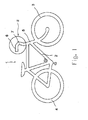
- a conventionally configured bicycle 1 can be seen.
- the bicycle 1 has a frame 2, a front wheel 3 and a rear wheel 4, and a steering column 5 for the front wheel 3.
- a tubular arm 6 is fixed by means of a stem 7.
- a control and / or display unit 8 in the manner of an HMI (Human-Machine-Interface) by means of a handlebar located on the handlebar tube 6 'of the arm 6 holder 9 is arranged above the handlebar stem 7.
- HMI Human-Machine-Interface
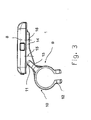
- the holder 9 comprises a fastening 10 for the fixation on the handlebar 6 and a receptacle 11 for the operating and / or display unit 8.
- the receptacle 11 is formed as a carrier, the carrier 11 projecting from the attachment 10 projecting.
- the attachment 10 is formed as a clamp.
- the clamp 10 is the handlebar tube 6 'surrounding the handlebar 6 attachable, and that is the clamp 10 by means of a in Fig. 2 indicated screw 12 by clamping on the handlebar tube 6 'attached.
- the carrier 11 has an obliquely with respect to the vertical of the clamp 10 outgoing strut 13 and an adjoining, approximately horizontally aligned rod member 14 as a support for the control and / or display unit 8.
- the operating and / or display unit 8 is attached to the rod member 14 by a screw 15 indicated only schematically.
- the control and / or display unit 8 by latching o. The like. Be attached to the rod member 14.
- the strut 13 closes with the rod member 14 at an angle of about 140 to 150 degrees. However, if desired, the angle may be between about 100 to 170 degrees.
- the strut 13 is aligned obliquely inwardly outwardly of the clamp 10 with respect to the horizontal.
- the adjoining the strut 13 bar element 14 is aligned approximately parallel to the clamp 10.
- the strut 13 and the rod member 14 have a different resonant frequency by the strut 13 and the rod member 14 have a different rigidity.
- the strut 13 and the rod member 14 may have a different cross section or consist of different materials with a different coefficient of elasticity. As a result, a high stability for the holder 9 is achieved
- the clamp 10 and / or the strut 13 and / or the rod member 14 are made of plastic, of a thermoplastic material. For good strength, it is advisable to use a glass fiber reinforced and / or glass ball reinforced plastic. Furthermore, the clamp 10, the strut 13 and the rod member 14 may be integrally formed by injection molding of thermoplastic material.
- the holder 9 for the operating and / or display unit 8 comprises two, each consisting of a fixture 10,10 'and a receptacle 11,11' existing elements.
- the operating and / or display unit 8 rests on two receptacles 11, 11 '.
- vibrations of the receptacle 11, 11 ' are largely damped in the horizontal direction. Vibrations can thus only occur in the vertical direction, but this is less critical for the operating and / or display unit 8.
- vibrations in the vertical direction can also be largely damped by appropriate choice of rigidity.
- the two elements 10/11, 10 '/ 11' are mutually mirror-symmetrical, such that a central fixing of the holder 9, the handlebar stem 7 surrounding the handlebar 6 is made possible.
- the holder 9 is not limited to the described and illustrated embodiment. On the contrary, it also includes all expert training courses within the framework the invention defined by the claims.
- the holder 9 according to the invention not only on a bicycle 1 but also on other vehicles, especially two-wheelers, which are controlled by a handlebar, use.
- the holder 9 can also be used on pedelecs, e-bikes, motorcycles, quads or the like for arranging an operating and / or display unit 8.
Landscapes
- Engineering & Computer Science (AREA)
- Mechanical Engineering (AREA)
- Steering Devices For Bicycles And Motorcycles (AREA)
Abstract
Description
- Die Erfindung betrifft eine Halterung für eine Bedien- und/oder Anzeigeeinheit nach dem Oberbegriff des Patentanspruchs 1.
- Eine derartige Halterung ist insbesondere für ein Fahrzeug mit einem Lenker, wie für ein Fahrrad, ein Pedelec, ein B-Bike ein Motorrad o. dgl., geeignet. Die Halterung dient zur Anordnung einer Bedien- und/oder Anzeigeeinheit in der Art einer HMI(Human-Maschine-Interface)-Einheit am Lenker.
- Eine solche Halterung für die Anordnung der Bedien- und/oder Anzeigeeinheit weist eine Befestigung für die Fixierung am Lenker auf. Desweiteren ist die Halterung mit einer Aufnahme für die Bedien- und/oder Anzeigeeinheit versehen. Es hat sich herausgestellt, dass es diesen Halterungen an Stabilität für die Bedien- und/oder Anzeigeeinheit, vor allem im rauen Fahrbetrieb des Fahrzeugs, mangelt. Für eine großbauenda Bedien- und/oder Anzeigeeinheit mit einer hohen Funktionalität, wie von heutigen HMI-Einheiten vermehrt geboten, erscheint die bekannte Halterung somit wenig geeignet.
- Der Erfindung liegt die Aufgabe zugrunde, die Halterung derart weiterzuentwickeln, dass deren Stabilität erhöht ist. Insbesondere soll eine Halterung mit einer möglichst zentralen und/oder stabilen und/oder diebstahlsicheren Befestigung des HMI's am Lenker geschaffen werden.
- Diese Aufgabe wird bei einer gattungsgemäßen Halterung durch die kennzeichnenden Merkmale des Anspruchs 1 gelöst
- Bei der erfindungsgsmäßen Halterung ist die Aufnahme als ein Träger ausgebildet, wobei der Träger auskragend von der Befestigung absteht. Geschaffen ist damit eine Halterung für die sichere sowie zuverlässige Anordnung eines HMI(human maschine interface) am Lenker eines Fahrzeugs. Weitere Ausgestaltungen der Erfindung sind Gegenstand der Unteransprüche.
- In zweckmäßiger weiterer Ausgestaltung kann die Befestigung als Schelle ausgebildet sein. Die Schelle kann das Lenkerrohr umgebend am Lenker anbringbar sein. In einfacher Art und Weise kann die Schelle mittels einer Verschraubung durch Klemmung am Lenkerrohr anbringbar sein.
- In besonders stabiler Ausgestaltung kann der Träger eine schräg bezüglich der Vertikalen von der Schelle abgehende Strebe sowie ein daran anschließendes, in etwa horizontal ausgerichtetes Stabelement als Auflage für die Bedien- und/oder Anzeigeeinheit aufweisen. Der ergonomischen Anordnung für den Benutzer halber kann es sich anbieten, dass die Strebe mit dem Stabelement einen Winkel von in etwa 100 bis 170 Grad einschließt. Als besonders bevorzugt hat sich dabei ein Winkel von in etwa 140 bis 150 Grad erwiesen. Desweiteren kann die Strebe von der Schelle schräg einwärts abgehend bezüglich der Horizontalen ausgerichtet sein. Das daran anschließende Stabelement ist in etwa parallel zur Schelle ausgerichtet. Es bietet sich in einfacher Art und Weise weiter an, die Bedien-und/oder Anzeigeeinheit am Stabelement durch Verschraubung, Verrastung o. dgl. zu befestigen.
- Zwecks Erhöhung der Stabilität im Fahrbetrieb des Fahrzeugs können die Strebe sowie das Stabelement eine unterschiedliche Resonanzfrequenz besitzen. Hiezu können die Strebe und das Stabelement eine unterschiedliche Steifigkeit aufweisen. Beispielsweise lässt sich die Steifigkeit durch einen unterschiedlichen Querschnitt, unterschiedliches Material o. dgl. für die Strebe und das Stabelement zweckgemäß anpassen.
- In kostengünstiger Art und Weise können die Schelle und/oder die Strebe und/oder das Stabelement aus Kunststoff bestehen. In kostengünstiger Weise sowie im Hinblick auf die einfache Verarbeitbarkeit kann es sich dabei um einen thermoplastischen Kunststoff handeln. Zwecks guter Stabilität bietet sich hierfür weiterhin ein glasfaserverstärkter, glaskugelverstärkter o. dgl. Kunststoff an. Der einfachen Herstellbarkeit halber können die Schelle, die Strebe sowie das Stabelement durch Spritzgießen von thermoplastischem Kunststoff einstückig ausgebildet sein.
- Eine besonders formstabile Ausgestaltung besteht weiterhin darin, dass die Halterung für die Bedien- und/oder Anzeigeeinheit zwei, jeweils aus einer Befestigung sowie einer Aufnahme bestehende Elemente umfasst. Dadurch liegt die Bedien- und/oder Anzeigeeinheit auf zwei Aufnahmen auf. Damit sind insbesondere Schwingungen der Aufnahme in horizontaler Richtung weitgehend gedämpft. Die beiden Elemente können zueinander spiegelsymmetrisch ausgebildet sein, derart dass eine mittige Fixierung der Halterung am Lenker ermöglicht ist.
- Für eine besonders bevorzugte Ausgestaltung ist nachfolgendes festzustellen. Geschaffen ist eine Integration von elektronischen Bauteilen am beziehungsweise im Zweirad, insbesondere für HMIs an Fahrrädern und/oder Pedelecs und/oder E-Bikes mit folgenden Eigenschaften:
- Die Konstruktion der Befestigungselemente erfolgt mit leicht unterschiedlichen Resonanzfrequenzen, um Eigenschwingungen zu reduzieren.
- Die Montage ist mittig und seitlich möglich.
- Es ist eine Dämpfung, insbesondere von Schwingungen, in einer Vorzugsrichtung zum Schutz der Elektronik erzielt.
- Die Halterung ist steif in allen anderen Richtungen.
- Die Halterung ist bei Bedarf leicht wechselbar.
- Die mit der Erfindung erzielten Vorteile bestehen insbesondere darin, dass eine Dämpfung der Eigenschwingungen sowie geringere Beschleunigungswerte während der Fahrt für die Halterung gegeben sind. Dadurch ist die Halterung besonders stabil. Die Bedien- und/oder Anzeigeeinheit ist somit betriebs- und funktionssicher am Lenker des Fahrzeugs angeordnet Ein Ausführungsbeispiel der Erfindung mit verschiedenen Weiterbildungen und Ausgestaltungen ist in den Zeichnungen dargestellt und wird im folgenden näher beschrieben. Es zeigen
-
Fig.1 ein Fahrrad in schematischer Ansicht, -
Fig. 2 einen Detailausschnitt gemäß Ziff. II ausFig.1 in perspektischer Ansicht und -
Fig. 3 eine Seitenansicht des Detailausschnitts gemäß Ziff. II ohne Lenker. - In
Fig. 1 ist ein in herkömmlicher Weise ausgestaltetes Fahrrad 1 zu sehen. Das Fahrrad 1 weist einen Rahmen 2, ein Vorderrad 3 sowie ein Hinterrad 4, und eine Lenksäule 5 für das Vorderrad 3 auf. An der Lenksäule 5 ist ein rohrförmiger Lenker 6 mittels eines Lenkervorbaus 7 befestigt. Wie näher inFig. 2 gezeigt ist, ist über dem Lenkervorbau 7 eine Bedien- und/oder Anzeigeeinheit 8 in der Art eines HMI(Human-Machine-Interface) mittels einer am Lenkerrohr 6' des Lenkers 6 befindlichen Halterung 9 angeordnet. - Die Halterung 9 umfasst eine Befestigung 10 für die Fixierung am Lenker 6 sowie eine Aufnahme 11 für die Bedien- und/oder Anzeigeeinheit 8. Wie man nähet in
Fig. 3 sieht, ist die Aufnahme 11 als ein Träger ausgebildet, wobei der Träger 11 auskragend von der Befestigung 10 absteht. Die Befestigung 10 ist als eine Schelle ausgebildet. Die Schelle 10 ist das Lenkerrohr 6' umgebend am Lenker 6 anbringbar, und zwar ist die Schelle 10 mittels einer inFig. 2 angedeuteten Verschraubung 12 durch Klemmung am Lenkerrohr 6' angebracht. - Wie man weiter anhand der
Fig. 3 sieht, weist der Träger 11 eine schräg bezüglich der Vertikalen von der Schelle 10 abgehende Strebe 13 sowie ein daran anschließendes, in etwa horizontal ausgerichtetes Stabelement 14 als Auflage für die Bedien- und/oder Anzeigeeinheit 8 auf. Die Bedien- und/oder Anzeigeeinheit 8 ist am Stabelement 14 durch eine lediglich schematisch angedeutete Verschraubung 15 befestigt. Selbstverständlich kann die Bedien- und/oder Anzeigeeinheit 8 auch durch Verrastung o. dgl. am Stabelement 14 befestigt sein. - Die Strebe 13 schließt mit dem Stabelement 14 einen Winkel von in etwa 140 bis 150 Grad ein. Falls gewünscht kann der Winkel jedoch auch zwischen in etwa 100 bis 170 Grad liegen. Die Strebe 13 ist von der Schelle 10 schräg einwärts abgehend bezüglich der Horizontalen ausgerichtet. Das an die Strebe 13 anschließende Stabelement 14 ist in etwa parallel zur Schelle 10 ausgerichtet. Weiter besitzen die Strebe 13 sowie das Stabelement 14 eine unterschiedliche Resonanzfrequenz, indem die Strebe 13 und das Stabelement 14 eine unterschiedliche Steifigkeit aufweisen. Beispielsweise können hierfür die Strebe 13 und das Stabelement 14 einen unterschiedlichen Querschnitt besitzen oder auch aus unterschiedlichen Materialien mit einem unterschiedlichen Elastizitätskoeffizienten bestehen. Dadurch wird eine hohe Stabilität für die Halterung 9 erzielt
- Die Schelle 10 und/oder die Strebe 13 und/oder das Stabelement 14 bestehen aus Kunststoff, und zwar aus einem thermoplastischen Kunststoff. Zwecks guter Festigkeit bietet es sich an, einen glasfaserverstärkten und/oder glaskugelverstärkten Kunststoff,zu verwenden. Weiterhin können die Schelle 10, die Strebe 13 sowie das Stabelement 14 durch Spritzgießen von thermoplastischem Kunststoff einstückig ausgebildet sein.
- Wie man weiter anhand von
Fig. 2 erkennt, umfasst die Halterung 9 für die Bedien-und/oder Anzeigeeinheit 8 zwei, jeweils aus einer Befestigung 10,10' sowie einer Aufnahme 11,11' bestehende Elemente. Dadurch liegt die Bedien- und/oder Anzeigeeinheit 8 auf zwei Aufnahmen 11,11' auf. Somit sind Schwingungen der Aufnahme 11, 11' in horizontaler Richtung weitgehend gedämpft. Schwingungen können damit lediglich in vertikaler Richtung auftreten, was jedoch für die Bedien- und/oder Anzeigeeinheit 8 weniger kritisch ist Wie bereits erwähnt können jedoch auch solche Schwingungen in vertikaler Richtung durch entsprechende Wahl der Steifigkeit weitgehend gedämpft werden. Die beiden Elemente 10/11, 10'/11' sind zueinander spiegelsymmetrisch ausgebildet, derart dass eine mittige Fixierung der Halterung 9, den Lenkervorbau 7 umgebend am Lenker 6 ermöglicht ist. - Die Erfindung ist nicht auf das beschriebene und dargestellte Ausführungsbeispiel beschränkt. Sie umfasst vielmehr auch alle fachmännischen Weiterbildungen im Rahmen der durch die Patentansprüche definierten Erfindung. So kann die erfindungsgemäße Halterung 9 nicht nur an einem Fahrrad 1 sondern auch an sonstigen Fahrzeugen, insbesondere Zweirädern, welche mit einem Lenker gesteuert werden, Verwendung finden. Beispielsweise kann die Halterung 9 auch an Pedelecs, E-Bikes, Motorräder, Quads o. dgl. zur Anordnung einer Bedien- und/oder Anzeigeeinheit 8 verwendet werden.
-
- 1:
- Fahrrad
- 2:
- Rahmen
- 3:
- Vorderrad
- 4:
- Hinterrad
- 5:
- Lenksäule
- 6:
- Lenker
- 6':
- Lenkerrohr
- 7:
- Lenkervorbau
- 8:
- Bedien- und/oder Anzeigeeinheit
- 9:
- Halterung
- 10,10':
- Befestigung / Schelle
- 11,11':
- Aufnahme / Träger
- 12:
- Verschraubung (für Schelle)
- 13:
- Strebe
- 14:
- Stabelement
- 15:
- Verschraubung (für Bedien- und/oder Anzeigeeinheit)
Claims (8)
- Halterung für eine Bedien- und/oder Anzeigeeinheit (8), insbesondere an einem Fahrzeug mit einem Lenker (6), wie einem Fahrrad (1), einem Pedelec, einem E-Bike, einem Motorrad o. dgl., mit einer Befestigung (10) für die Fixierung am Lenker (6), und mit einer Aufnahme (11) für die Bedien- und/oder Anzeigeeinheit (8), dadurch gekennzeichnet, dass die Aufnahme (11) als ein Träger ausgebildet ist, und dass der Träger (11) auskragend von der Befestigung (10) absteht.
- Halterung nach Anspruch 1, dadurch gekennzeichnet, dass die Befestigung (10) als Schelle ausgebildet ist, wobei vorzugsweise die Schelle (10) das Lenkerrohr (6') umgebend am Lenker (6) anbringbar ist, und wobei weiter vorzugsweise die schelle (10) mittels einer Verschraubung (12) durch Klemmung am Lenkerrohr (6') anbringbar ist.
- Halterung nach Anspruch 1 oder 2, dadurch gekennzeichnet, dass der Träger (11) eine schräg bezüglich der Vertikalen von der Schelle (10) abgehende Strebe (13) sowie ein daran anschließendes, in etwa horizontal ausgerichtetes Stabelement (14) als Auflage für die Bedien- und/oder Anzeigeeinheit (8) aufweist, insbesondere derart dass die Strebe (13) mit dem Stabelement (14) einen Winkel von in etwa 100 bis 170 Grad, bevorzugterweise von 140 bis 150 Grad, einschließt.
- Halterung nach Anspruch 1, 2 oder 3, dadurch gekennzeichnet, dass die Strebe (13) von der Schelle (10) schräg einwärts abgehend bezüglich der Horizontalen ausgerichtet ist, und dass das daran anschließende Stabelement (14) in etwa parallel zur Schelle (10) ausgerichtet ist.
- Halterung nach einem der Ansprüche 1 bis 4, dadurch gekennzeichnet, dass die Strebe (13) sowie das Stabelement (14) eine unterschiedliche Resonanzfrequenz besitzen, insbesondere indem die Strebe (13) und das Stabelement (14) eine unterschiedliche Steifigkeit beilspielsweise durch einen unterschiedlichen Querschnitt, unterschiedliches Material o. dgl., aufweisen.
- Halterung nach einem der Ansprüche 1 bis 5, dadurch gekennzeichnet, dass die Bedien- und/oder Anzeigeeinheit (8) am Stabelement (14) durch Verschraubung (15), Verrastung o. dgl. befestigt ist.
- Halterung nach einem der Ansprüche 1 bis 6, dadurch gekennzeichnet, dass die Schelle (10) und/oder die Strebe (13) und/oder das Stabelement (14) aus Kunststoff, bestehen, insbesondere aus einem thermoplastischen Kunststoff und/oder aus einem glasfaserverstärkten, glaskugelverstärkten o. dgl. Kunststoff, und dass vorzugsweise die Schelle (10), die Strebe (13) sowie das Stabelement (14) durch Spritzgießen von thermoplastischem Kunststoff einstückig ausgebildet sind.
- Halterung nach einem der Ansprüche 1 bis 7, dadurch gekennzeichnet, dass die Halterung (9) für die Bedien- und/oder Anzeigeeinheit (8) zwei, jeweils aus einer Befestigung (10, 10') sowie einer Aufnahme (11,11') bestehende Elemente umfasst derart dass die Bedien- und/oder Anzeigeeinheit (8) auf zwei Aufnahmen (11,11') aufliegt, wobei insbesondere Schwingungen der Aufnahme (11,11') in horizontaler Richtung weitgehend gedämpft sind, und dass vorzugweise die beiden Elemente (10/11, 10'/11') zueinander spiegelsymmetrisch ausgebildet sind, derart dass eine mittige Fixierung am Lenker (6) ermöglicht ist.
Applications Claiming Priority (1)
| Application Number | Priority Date | Filing Date | Title |
|---|---|---|---|
| DE102012016098 | 2012-08-15 |
Publications (3)
| Publication Number | Publication Date |
|---|---|
| EP2698308A2 true EP2698308A2 (de) | 2014-02-19 |
| EP2698308A3 EP2698308A3 (de) | 2015-03-18 |
| EP2698308B1 EP2698308B1 (de) | 2019-09-18 |
Family
ID=49028883
Family Applications (1)
| Application Number | Title | Priority Date | Filing Date |
|---|---|---|---|
| EP13004044.7A Active EP2698308B1 (de) | 2012-08-15 | 2013-08-14 | Halterung für eine Bedien- und/oder Anzeigeeinheit |
Country Status (2)
| Country | Link |
|---|---|
| EP (1) | EP2698308B1 (de) |
| DE (1) | DE102013013187A1 (de) |
Cited By (1)
| Publication number | Priority date | Publication date | Assignee | Title |
|---|---|---|---|---|
| CN114080329A (zh) * | 2019-06-06 | 2022-02-22 | 罗伯特·博世有限公司 | 用于车辆仪器的具有磁保险销的保持装置 |
Family Cites Families (12)
| Publication number | Priority date | Publication date | Assignee | Title |
|---|---|---|---|---|
| JP3490239B2 (ja) * | 1997-01-31 | 2004-01-26 | 株式会社シマノ | 自転車用表示装置の取付具 |
| DE29819852U1 (de) * | 1998-11-06 | 1999-03-18 | Löhr GmbH, 59199 Bönen | Navigationssystem für ein Fahrrad |
| US6305241B1 (en) * | 1999-06-28 | 2001-10-23 | Shimano, Inc. | Handlebar adapter for mounting a bicycle display |
| US6265967B1 (en) * | 2000-02-29 | 2001-07-24 | Shimano Inc. | Display device for bicycle |
| DE10141750A1 (de) * | 2001-08-29 | 2003-03-20 | Rainer Oberheim | Fahrrad mit elektronischem Anzeigegerät |
| DE20119499U1 (de) * | 2001-11-30 | 2002-02-21 | Lin, Ching-Yih, Shiushui Hsiang, Changhua | Zusatzeinrichtung eines Fahrrads zur Aufnahme von zusätzlichen Ausstattungen |
| DE20314073U1 (de) * | 2003-09-09 | 2003-11-06 | Busch & Müller KG, 58540 Meinerzhagen | Halterung für elektrische bzw. elektronische Bauteile an einem Fahrrad |
| FR2868034B3 (fr) * | 2004-03-26 | 2006-06-09 | Presse Etude Sa | Dispositif porte carte |
| US7448297B2 (en) * | 2004-08-04 | 2008-11-11 | Shimano (Singapore) Pte., Ltd | Mountable bicycle structure |
| FR2904424B1 (fr) * | 2006-07-28 | 2009-08-21 | Salomon Sa | Dispositif de mesure de vitesse notamment pour cycle |
| KR101124166B1 (ko) * | 2009-12-04 | 2012-03-27 | 손대업 | 라이트 거치장치 |
| US8556143B2 (en) * | 2011-02-08 | 2013-10-15 | Adaptiv Technologies Llc | Mounting apparatus |
-
2013
- 2013-08-09 DE DE102013013187.1A patent/DE102013013187A1/de not_active Withdrawn
- 2013-08-14 EP EP13004044.7A patent/EP2698308B1/de active Active
Cited By (1)
| Publication number | Priority date | Publication date | Assignee | Title |
|---|---|---|---|---|
| CN114080329A (zh) * | 2019-06-06 | 2022-02-22 | 罗伯特·博世有限公司 | 用于车辆仪器的具有磁保险销的保持装置 |
Also Published As
| Publication number | Publication date |
|---|---|
| EP2698308B1 (de) | 2019-09-18 |
| DE102013013187A1 (de) | 2014-02-20 |
| EP2698308A3 (de) | 2015-03-18 |
Similar Documents
| Publication | Publication Date | Title |
|---|---|---|
| DE102012222347A1 (de) | Klemmbaugruppe zur Befestigung eines Lenkstangengriffes | |
| EP3736200B1 (de) | Lenkervorbau sowie vorbausystem | |
| EP2698308B1 (de) | Halterung für eine Bedien- und/oder Anzeigeeinheit | |
| DE102013224562A1 (de) | Vorrichtung zur Aufnahme eines Endschalldämpfers eines Zweirads | |
| DE4101998A1 (de) | Fahrradrahmen | |
| EP3178731B1 (de) | Radschützer für das vorderrad eines zweirades | |
| DE102004040679A1 (de) | Fahrradsattel | |
| DE102004053452B3 (de) | Befestigungsvorrichtung für einen Monitor an einem Fahrzeugsitz | |
| DE102020118491A1 (de) | Elektrofahrräder mit Hinterradfederung | |
| EP0785125A2 (de) | Vorrichtung zur externen Sicherung gegen Verdrehung, zur Ausfahrbegrenzung und zur Diebstahlsicherung einer hydraulisch positionierbaren Sattelstütze | |
| EP4173938A1 (de) | Fahrradlenker aus kunststoff | |
| DE4231095C2 (de) | Befestigung von Sitzschienen eines Vordersitzes in einem Kraftfahrzeug | |
| CH682904A5 (de) | Einrichtung mit mindestens einer Federeinheit zwischen dem Lenker und dem Gabelschaft eines Fahrrades. | |
| DE102006010817B4 (de) | Lenkervorbaukappe | |
| WO2015071480A1 (de) | Fahrradlenker-system | |
| DE2501208A1 (de) | Aufsatz fuer zweiraeder | |
| DE102017210267B4 (de) | Fahrradrahmen und Fahrrad, insbesondere Elektrofahrrad | |
| DE3936342A1 (de) | Abfederungsmechanismus fuer zweiraeder aller art | |
| DE202018101690U1 (de) | Fußrastenvorrichtung | |
| DE4317908C2 (de) | Haltevorrichtung für ein Fahrrad | |
| DE202022101036U1 (de) | Fahrrad, insbesondere Elektrofahrrad mit modularem Hinterbau | |
| DE202024107250U1 (de) | Fahrradschutzblechhalterung | |
| DE202024101660U1 (de) | Fahrradrahmen mit Mittelständeranschluss | |
| DE823262C (de) | Federung fuer Rahmen von Fahrraedern und aehnlichen Fahrzeugen | |
| DE20000922U1 (de) | Anordnung zum Befestigen von Sätteln, Sitzen o.dgl. auf Fahrzeugrahmen von Einspurfahrzeugen |
Legal Events
| Date | Code | Title | Description |
|---|---|---|---|
| AK | Designated contracting states |
Kind code of ref document: A2 Designated state(s): AL AT BE BG CH CY CZ DE DK EE ES FI FR GB GR HR HU IE IS IT LI LT LU LV MC MK MT NL NO PL PT RO RS SE SI SK SM TR |
|
| AX | Request for extension of the european patent |
Extension state: BA ME |
|
| PUAI | Public reference made under article 153(3) epc to a published international application that has entered the european phase |
Free format text: ORIGINAL CODE: 0009012 |
|
| PUAL | Search report despatched |
Free format text: ORIGINAL CODE: 0009013 |
|
| AK | Designated contracting states |
Kind code of ref document: A3 Designated state(s): AL AT BE BG CH CY CZ DE DK EE ES FI FR GB GR HR HU IE IS IT LI LT LU LV MC MK MT NL NO PL PT RO RS SE SI SK SM TR |
|
| AX | Request for extension of the european patent |
Extension state: BA ME |
|
| RIC1 | Information provided on ipc code assigned before grant |
Ipc: B62J 99/00 20090101ALI20150206BHEP Ipc: B62J 11/00 20060101AFI20150206BHEP |
|
| 17P | Request for examination filed |
Effective date: 20150622 |
|
| RBV | Designated contracting states (corrected) |
Designated state(s): AL AT BE BG CH CY CZ DE DK EE ES FI FR GB GR HR HU IE IS IT LI LT LU LV MC MK MT NL NO PL PT RO RS SE SI SK SM TR |
|
| STAA | Information on the status of an ep patent application or granted ep patent |
Free format text: STATUS: EXAMINATION IS IN PROGRESS |
|
| 17Q | First examination report despatched |
Effective date: 20180102 |
|
| GRAP | Despatch of communication of intention to grant a patent |
Free format text: ORIGINAL CODE: EPIDOSNIGR1 |
|
| STAA | Information on the status of an ep patent application or granted ep patent |
Free format text: STATUS: GRANT OF PATENT IS INTENDED |
|
| INTG | Intention to grant announced |
Effective date: 20190516 |
|
| GRAS | Grant fee paid |
Free format text: ORIGINAL CODE: EPIDOSNIGR3 |
|
| GRAA | (expected) grant |
Free format text: ORIGINAL CODE: 0009210 |
|
| STAA | Information on the status of an ep patent application or granted ep patent |
Free format text: STATUS: THE PATENT HAS BEEN GRANTED |
|
| AK | Designated contracting states |
Kind code of ref document: B1 Designated state(s): AL AT BE BG CH CY CZ DE DK EE ES FI FR GB GR HR HU IE IS IT LI LT LU LV MC MK MT NL NO PL PT RO RS SE SI SK SM TR |
|
| REG | Reference to a national code |
Ref country code: GB Ref legal event code: FG4D Free format text: NOT ENGLISH |
|
| REG | Reference to a national code |
Ref country code: CH Ref legal event code: EP |
|
| REG | Reference to a national code |
Ref country code: DE Ref legal event code: R096 Ref document number: 502013013592 Country of ref document: DE |
|
| REG | Reference to a national code |
Ref country code: AT Ref legal event code: REF Ref document number: 1180968 Country of ref document: AT Kind code of ref document: T Effective date: 20191015 |
|
| REG | Reference to a national code |
Ref country code: IE Ref legal event code: FG4D Free format text: LANGUAGE OF EP DOCUMENT: GERMAN |
|
| REG | Reference to a national code |
Ref country code: NL Ref legal event code: MP Effective date: 20190918 |
|
| PG25 | Lapsed in a contracting state [announced via postgrant information from national office to epo] |
Ref country code: NO Free format text: LAPSE BECAUSE OF FAILURE TO SUBMIT A TRANSLATION OF THE DESCRIPTION OR TO PAY THE FEE WITHIN THE PRESCRIBED TIME-LIMIT Effective date: 20191218 Ref country code: SE Free format text: LAPSE BECAUSE OF FAILURE TO SUBMIT A TRANSLATION OF THE DESCRIPTION OR TO PAY THE FEE WITHIN THE PRESCRIBED TIME-LIMIT Effective date: 20190918 Ref country code: FI Free format text: LAPSE BECAUSE OF FAILURE TO SUBMIT A TRANSLATION OF THE DESCRIPTION OR TO PAY THE FEE WITHIN THE PRESCRIBED TIME-LIMIT Effective date: 20190918 Ref country code: LT Free format text: LAPSE BECAUSE OF FAILURE TO SUBMIT A TRANSLATION OF THE DESCRIPTION OR TO PAY THE FEE WITHIN THE PRESCRIBED TIME-LIMIT Effective date: 20190918 Ref country code: HR Free format text: LAPSE BECAUSE OF FAILURE TO SUBMIT A TRANSLATION OF THE DESCRIPTION OR TO PAY THE FEE WITHIN THE PRESCRIBED TIME-LIMIT Effective date: 20190918 Ref country code: BG Free format text: LAPSE BECAUSE OF FAILURE TO SUBMIT A TRANSLATION OF THE DESCRIPTION OR TO PAY THE FEE WITHIN THE PRESCRIBED TIME-LIMIT Effective date: 20191218 |
|
| REG | Reference to a national code |
Ref country code: LT Ref legal event code: MG4D |
|
| PG25 | Lapsed in a contracting state [announced via postgrant information from national office to epo] |
Ref country code: AL Free format text: LAPSE BECAUSE OF FAILURE TO SUBMIT A TRANSLATION OF THE DESCRIPTION OR TO PAY THE FEE WITHIN THE PRESCRIBED TIME-LIMIT Effective date: 20190918 Ref country code: LV Free format text: LAPSE BECAUSE OF FAILURE TO SUBMIT A TRANSLATION OF THE DESCRIPTION OR TO PAY THE FEE WITHIN THE PRESCRIBED TIME-LIMIT Effective date: 20190918 Ref country code: GR Free format text: LAPSE BECAUSE OF FAILURE TO SUBMIT A TRANSLATION OF THE DESCRIPTION OR TO PAY THE FEE WITHIN THE PRESCRIBED TIME-LIMIT Effective date: 20191219 Ref country code: RS Free format text: LAPSE BECAUSE OF FAILURE TO SUBMIT A TRANSLATION OF THE DESCRIPTION OR TO PAY THE FEE WITHIN THE PRESCRIBED TIME-LIMIT Effective date: 20190918 |
|
| PG25 | Lapsed in a contracting state [announced via postgrant information from national office to epo] |
Ref country code: RO Free format text: LAPSE BECAUSE OF FAILURE TO SUBMIT A TRANSLATION OF THE DESCRIPTION OR TO PAY THE FEE WITHIN THE PRESCRIBED TIME-LIMIT Effective date: 20190918 Ref country code: ES Free format text: LAPSE BECAUSE OF FAILURE TO SUBMIT A TRANSLATION OF THE DESCRIPTION OR TO PAY THE FEE WITHIN THE PRESCRIBED TIME-LIMIT Effective date: 20190918 Ref country code: PL Free format text: LAPSE BECAUSE OF FAILURE TO SUBMIT A TRANSLATION OF THE DESCRIPTION OR TO PAY THE FEE WITHIN THE PRESCRIBED TIME-LIMIT Effective date: 20190918 Ref country code: PT Free format text: LAPSE BECAUSE OF FAILURE TO SUBMIT A TRANSLATION OF THE DESCRIPTION OR TO PAY THE FEE WITHIN THE PRESCRIBED TIME-LIMIT Effective date: 20200120 Ref country code: NL Free format text: LAPSE BECAUSE OF FAILURE TO SUBMIT A TRANSLATION OF THE DESCRIPTION OR TO PAY THE FEE WITHIN THE PRESCRIBED TIME-LIMIT Effective date: 20190918 Ref country code: EE Free format text: LAPSE BECAUSE OF FAILURE TO SUBMIT A TRANSLATION OF THE DESCRIPTION OR TO PAY THE FEE WITHIN THE PRESCRIBED TIME-LIMIT Effective date: 20190918 Ref country code: IT Free format text: LAPSE BECAUSE OF FAILURE TO SUBMIT A TRANSLATION OF THE DESCRIPTION OR TO PAY THE FEE WITHIN THE PRESCRIBED TIME-LIMIT Effective date: 20190918 |
|
| PG25 | Lapsed in a contracting state [announced via postgrant information from national office to epo] |
Ref country code: CZ Free format text: LAPSE BECAUSE OF FAILURE TO SUBMIT A TRANSLATION OF THE DESCRIPTION OR TO PAY THE FEE WITHIN THE PRESCRIBED TIME-LIMIT Effective date: 20190918 Ref country code: SM Free format text: LAPSE BECAUSE OF FAILURE TO SUBMIT A TRANSLATION OF THE DESCRIPTION OR TO PAY THE FEE WITHIN THE PRESCRIBED TIME-LIMIT Effective date: 20190918 Ref country code: IS Free format text: LAPSE BECAUSE OF FAILURE TO SUBMIT A TRANSLATION OF THE DESCRIPTION OR TO PAY THE FEE WITHIN THE PRESCRIBED TIME-LIMIT Effective date: 20200224 Ref country code: SK Free format text: LAPSE BECAUSE OF FAILURE TO SUBMIT A TRANSLATION OF THE DESCRIPTION OR TO PAY THE FEE WITHIN THE PRESCRIBED TIME-LIMIT Effective date: 20190918 |
|
| REG | Reference to a national code |
Ref country code: DE Ref legal event code: R097 Ref document number: 502013013592 Country of ref document: DE |
|
| PLBE | No opposition filed within time limit |
Free format text: ORIGINAL CODE: 0009261 |
|
| STAA | Information on the status of an ep patent application or granted ep patent |
Free format text: STATUS: NO OPPOSITION FILED WITHIN TIME LIMIT |
|
| PG2D | Information on lapse in contracting state deleted |
Ref country code: IS |
|
| PG25 | Lapsed in a contracting state [announced via postgrant information from national office to epo] |
Ref country code: DK Free format text: LAPSE BECAUSE OF FAILURE TO SUBMIT A TRANSLATION OF THE DESCRIPTION OR TO PAY THE FEE WITHIN THE PRESCRIBED TIME-LIMIT Effective date: 20190918 Ref country code: IS Free format text: LAPSE BECAUSE OF FAILURE TO SUBMIT A TRANSLATION OF THE DESCRIPTION OR TO PAY THE FEE WITHIN THE PRESCRIBED TIME-LIMIT Effective date: 20200119 |
|
| 26N | No opposition filed |
Effective date: 20200619 |
|
| PG25 | Lapsed in a contracting state [announced via postgrant information from national office to epo] |
Ref country code: SI Free format text: LAPSE BECAUSE OF FAILURE TO SUBMIT A TRANSLATION OF THE DESCRIPTION OR TO PAY THE FEE WITHIN THE PRESCRIBED TIME-LIMIT Effective date: 20190918 |
|
| REG | Reference to a national code |
Ref country code: DE Ref legal event code: R082 Ref document number: 502013013592 Country of ref document: DE Representative=s name: JOSTARNDT PATENTANWALTS-AG, DE |
|
| PG25 | Lapsed in a contracting state [announced via postgrant information from national office to epo] |
Ref country code: MC Free format text: LAPSE BECAUSE OF FAILURE TO SUBMIT A TRANSLATION OF THE DESCRIPTION OR TO PAY THE FEE WITHIN THE PRESCRIBED TIME-LIMIT Effective date: 20190918 |
|
| REG | Reference to a national code |
Ref country code: CH Ref legal event code: PL |
|
| GBPC | Gb: european patent ceased through non-payment of renewal fee |
Effective date: 20200814 |
|
| PG25 | Lapsed in a contracting state [announced via postgrant information from national office to epo] |
Ref country code: LU Free format text: LAPSE BECAUSE OF NON-PAYMENT OF DUE FEES Effective date: 20200814 Ref country code: LI Free format text: LAPSE BECAUSE OF NON-PAYMENT OF DUE FEES Effective date: 20200831 Ref country code: CH Free format text: LAPSE BECAUSE OF NON-PAYMENT OF DUE FEES Effective date: 20200831 |
|
| REG | Reference to a national code |
Ref country code: BE Ref legal event code: MM Effective date: 20200831 |
|
| PG25 | Lapsed in a contracting state [announced via postgrant information from national office to epo] |
Ref country code: FR Free format text: LAPSE BECAUSE OF NON-PAYMENT OF DUE FEES Effective date: 20200831 |
|
| PG25 | Lapsed in a contracting state [announced via postgrant information from national office to epo] |
Ref country code: IE Free format text: LAPSE BECAUSE OF NON-PAYMENT OF DUE FEES Effective date: 20200814 Ref country code: GB Free format text: LAPSE BECAUSE OF NON-PAYMENT OF DUE FEES Effective date: 20200814 Ref country code: BE Free format text: LAPSE BECAUSE OF NON-PAYMENT OF DUE FEES Effective date: 20200831 |
|
| REG | Reference to a national code |
Ref country code: AT Ref legal event code: MM01 Ref document number: 1180968 Country of ref document: AT Kind code of ref document: T Effective date: 20200814 |
|
| PG25 | Lapsed in a contracting state [announced via postgrant information from national office to epo] |
Ref country code: AT Free format text: LAPSE BECAUSE OF NON-PAYMENT OF DUE FEES Effective date: 20200814 |
|
| PG25 | Lapsed in a contracting state [announced via postgrant information from national office to epo] |
Ref country code: TR Free format text: LAPSE BECAUSE OF FAILURE TO SUBMIT A TRANSLATION OF THE DESCRIPTION OR TO PAY THE FEE WITHIN THE PRESCRIBED TIME-LIMIT Effective date: 20190918 Ref country code: MT Free format text: LAPSE BECAUSE OF FAILURE TO SUBMIT A TRANSLATION OF THE DESCRIPTION OR TO PAY THE FEE WITHIN THE PRESCRIBED TIME-LIMIT Effective date: 20190918 Ref country code: CY Free format text: LAPSE BECAUSE OF FAILURE TO SUBMIT A TRANSLATION OF THE DESCRIPTION OR TO PAY THE FEE WITHIN THE PRESCRIBED TIME-LIMIT Effective date: 20190918 |
|
| PG25 | Lapsed in a contracting state [announced via postgrant information from national office to epo] |
Ref country code: MK Free format text: LAPSE BECAUSE OF FAILURE TO SUBMIT A TRANSLATION OF THE DESCRIPTION OR TO PAY THE FEE WITHIN THE PRESCRIBED TIME-LIMIT Effective date: 20190918 |
|
| REG | Reference to a national code |
Ref country code: DE Ref legal event code: R082 Ref document number: 502013013592 Country of ref document: DE |
|
| P01 | Opt-out of the competence of the unified patent court (upc) registered |
Effective date: 20230522 |
|
| PGFP | Annual fee paid to national office [announced via postgrant information from national office to epo] |
Ref country code: DE Payment date: 20240819 Year of fee payment: 12 |
|
| REG | Reference to a national code |
Ref country code: DE Ref legal event code: R119 Ref document number: 502013013592 Country of ref document: DE |