EP2697869B1 - Steckverbinder mit einem kontaktelement - Google Patents
Steckverbinder mit einem kontaktelement Download PDFInfo
- Publication number
- EP2697869B1 EP2697869B1 EP12702187.1A EP12702187A EP2697869B1 EP 2697869 B1 EP2697869 B1 EP 2697869B1 EP 12702187 A EP12702187 A EP 12702187A EP 2697869 B1 EP2697869 B1 EP 2697869B1
- Authority
- EP
- European Patent Office
- Prior art keywords
- contact
- type connector
- housing
- making member
- making
- Prior art date
- Legal status (The legal status is an assumption and is not a legal conclusion. Google has not performed a legal analysis and makes no representation as to the accuracy of the status listed.)
- Not-in-force
Links
Images


Classifications
-
- H—ELECTRICITY
- H01—ELECTRIC ELEMENTS
- H01R—ELECTRICALLY-CONDUCTIVE CONNECTIONS; STRUCTURAL ASSOCIATIONS OF A PLURALITY OF MUTUALLY-INSULATED ELECTRICAL CONNECTING ELEMENTS; COUPLING DEVICES; CURRENT COLLECTORS
- H01R13/00—Details of coupling devices of the kinds covered by groups H01R12/70 or H01R24/00 - H01R33/00
- H01R13/44—Means for preventing access to live contacts
- H01R13/447—Shutter or cover plate
- H01R13/453—Shutter or cover plate opened by engagement of counterpart
-
- H—ELECTRICITY
- H01—ELECTRIC ELEMENTS
- H01R—ELECTRICALLY-CONDUCTIVE CONNECTIONS; STRUCTURAL ASSOCIATIONS OF A PLURALITY OF MUTUALLY-INSULATED ELECTRICAL CONNECTING ELEMENTS; COUPLING DEVICES; CURRENT COLLECTORS
- H01R13/00—Details of coupling devices of the kinds covered by groups H01R12/70 or H01R24/00 - H01R33/00
- H01R13/44—Means for preventing access to live contacts
- H01R13/447—Shutter or cover plate
- H01R13/453—Shutter or cover plate opened by engagement of counterpart
- H01R13/4538—Covers sliding or withdrawing in the direction of engagement
-
- H—ELECTRICITY
- H01—ELECTRIC ELEMENTS
- H01R—ELECTRICALLY-CONDUCTIVE CONNECTIONS; STRUCTURAL ASSOCIATIONS OF A PLURALITY OF MUTUALLY-INSULATED ELECTRICAL CONNECTING ELEMENTS; COUPLING DEVICES; CURRENT COLLECTORS
- H01R13/00—Details of coupling devices of the kinds covered by groups H01R12/70 or H01R24/00 - H01R33/00
- H01R13/02—Contact members
- H01R13/22—Contacts for co-operating by abutting
- H01R13/24—Contacts for co-operating by abutting resilient; resiliently-mounted
- H01R13/2407—Contacts for co-operating by abutting resilient; resiliently-mounted characterized by the resilient means
- H01R13/2421—Contacts for co-operating by abutting resilient; resiliently-mounted characterized by the resilient means using coil springs
Definitions
- the present invention relates to a connector for producing at least one electrical contact, in particular charging plug or high-current plug, with a housing and at least one disposed in the housing first contact element, wherein the housing has a plug-side end, which is designed for plug-in connection with a complementary connector and wherein the at least one first contact element has a free end which faces the plug-side end, wherein at least a first contact element of the connector and at least a part of the housing between a first position, in which the first contact element is retracted into the housing, and a second position, in which the free end of the first contact element is exposed, are movable relative to each other, wherein at least one second contact element is provided, which fixed with respect to the part of the housing and the first contact element angeor dnet, wherein the second contact element is electrically connected to the movable first contact element via an electrical sliding contact "according to the preamble of claim 1.
- a high current connector for transmitting electrical currents has a housing made of electrically conductive material, which is designed for mechanical and electrical connection to a cable and an open side for insertion of a Having mating connector made of an electrically conductive material. Furthermore, a contact element is provided, which is arranged and formed in the housing such that it produces an electrical contact with contact surface and contact pressure between the housing and the mating plug connector inserted therein.
- the contact element has at least one annular coil spring.
- the invention has for its object to provide a connector of o.g. To design a type such that the security is improved for an operator using this plug, so that the connector is also suitable for applications in the field of high electrical currents and voltages.
- the sliding contact comprises at least one coil spring which electrically contacts the first and the second contact element with a respective contact pressure of a respective contact surface with opposite radial outer sides of helical turns.
- the connector is also suitable for applications in which an electrical voltage is applied to the first contact element or elements even in the unplugged state.
- the good electrical contact is not adversely affected by the relative movement between the first and second contact element.
- the at least one first contact element for electrically contacting a complementary contact element in the complementary connector, when the connector is plugged into the complementary connector is formed.
- a coupler or female connector of the connector For connection to a coupler or female connector of the connector is designed as a male connector and at least a first contact element as a contact pin.
- a linear connector is achieved in that the first contact element and / or the part of the housing in the direction parallel to a plug-in direction of the connector in the complementary connector is movable.
- a particularly good contact protection of the first contact element or elements is achieved in that the housing has at the plug-side end a cover made of an electrically insulating material, wherein the at least one first contact element in the first position within a space defined by the housing and the cover is arranged and extends in the second position through the cover and out of this outstanding.
- a particularly reliable and functionally reliable contact protection is achieved in that the cover and the housing are integrally formed with each other.
- a further improvement of the contact protection is achieved in that at the free end of at least one first contact element, an end cap made of an electrically insulating material is arranged, which completely covers the free end.
- An improvement in the reliability of the electrical contact between the first and second contact element is achieved in that the at least one coil spring is fixedly attached to the first contact element.
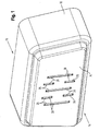
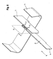
- the in the Fig. 1 to 8 illustrated, preferred embodiment of a connector according to the invention comprises a housing 10 made of an electrically insulating material in which seven first contact elements 12 are arranged.
- the holder and bearing of the first contact elements 12 relative to the housing 10 is not shown for reasons of clarity in all figures.
- the first contact elements 12 are plate-shaped and arranged substantially parallel to each other, so that respective wide sides 22 of adjacent first contact elements 12 face each other.
- the housing 10 has a male end 14 for mating engagement with a complementary connector (not shown) and a cable end 16 for electrical and mechanical connection to an electrically conductive cable (not shown).
- the connector is shown to the plug-side end 14 and the cable end 16 is cut off.
- the cable-side end 16 and the plug-side end 14 of the housing 10 is cut off.
- the first contact elements 12 each have a free end 18, which faces the plug-side end 14. On the free end 18, an end cap 20 made of an electrically insulating material is applied to each end face. Otherwise, the first contact elements 12 are made of an electrically conductive material and destined to an electrical contact corresponding contact elements in a complementary, mating with the connector according to the invention complementary connector (not shown) produce.
- the housing 10 has a cover 24, which has openings 26 which are designed and arranged such that in each case a first contact element 12 engages through an opening 26.
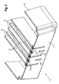
- the first contact elements 12 are movable relative to the housing 10 between a first position, as in FIG Fig. 1 and 2 represented, and a second position, as in Fig. 5 and 6 represented movably arranged.
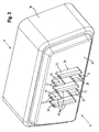
- the Fig. 3 and 4 branch an intermediate position of the first contact elements 12 between the first and second position.
- a mechanism for moving the first contact elements 12 for reasons of clarity is not shown.
- the first position the first contact elements 12 are retracted into a space bounded by the housing 10 and the cover 24.
- the first contact elements 12 are pushed out of the housing 10 through the apertures 26 and accordingly project beyond the cover 24 or the housing 10 in the direction of the plug-side end 14.
- the first contact elements 12 are extended from the first position through the cover 24 through to the second position, so that the first contact elements 12 electrically contact corresponding contact elements in the complementary connector. Conversely, before pulling back again from the connector according to the invention and the complementary connector, the first contact elements 12 are withdrawn from the second position back to the first position.
- a corresponding first securing mechanism is provided, which only allows a movement of the first contact elements 12 from the first position to the second position when the connector according to the invention is fully inserted into the complementary connector.
- a second securing mechanism is preferably provided, which prevents disassembly of the connector according to the invention and the complementary connector, as long as the first contact elements are outside the first position.
- the connector according to the invention is connected at its cable end 16 with at least one electrically conductive cable.
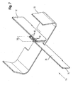
- a second contact element 28 fixed relative to the housing 10 is provided for each movable first contact element 12, as in FIG Fig. 7 and 8th shown. In the Fig. 7 and 8th For reasons of better clarity, only one pair of first and second contact elements 12, 28 is shown.
- the second contact elements 28 are plate-shaped and in each case a pair of first and second contact element 12, 28 are arranged parallel to each other such that respective wide sides of the first and second contact element 12, 28 facing each other. Furthermore, in an overlap region 30 between the plate-shaped contact elements 12, 28 of a pair of first and second contact elements 12, 28, at least one helical spring 32 made of an electrically conductive and spring-elastic material is arranged.
- a diameter the helical spring 32 and a distance of the plate-shaped contact elements 12, 28 and the wide sides 22 of a pair of first and second contact element 12,28 in the overlap region 30 is selected such that respective helical coils of the coil spring 32 having a first radial outside at the first Contact element 12 and with one of the first radial outer side opposite second outer side abut the second contact element 28, so that there is an electrical contact point with contact surface and contact pressure between the turns of the coil spring 32 and the respective contact element 12, 28.
- the contact pressure adjusts itself in that the turns of the helical spring 32 are deflected out of a respective rest position relative to a longitudinal axis of the helical spring 32 or are tilted relative to the longitudinal axis of the helical spring 32. This is achieved in that a distance of the plate-shaped contact elements 12, 28 of a pair of first and second contact element 12, 28 is smaller than an outer diameter of the coil spring 32nd
- the coil spring 32 is attached to the first contact element 12, so that the coil spring 32 moves with the first contact element 12. Accordingly, the turns of the coil spring 32 upon movement of the first contact element 12 along the second contact element 28 and thereby maintain a sufficient electrical connection between the two contact elements 12, 28 upright.
- the second contact elements 28 each have a free end with an end face 34 on the front side, this free end facing the cable end 16 of the connector according to the invention.
- the front end face 34 serves, for example, for electrical contacting with a wire or electrical line of a cable to be connected to the connector according to the invention.
- the helical spring 32 is preferably annular and defines within this ring an area space. This surface is aligned at the boundaries of the coil spring 32 parallel to a longitudinal axis of the coil spring 32 at the appropriate location. Due to the annular formation of the Coil spring 32 forms this in principle a torus in space, which has two opposite axial end sides. According to the invention, the helical spring 32 is arranged in the overlapping region 30 between the two contact elements 12, 28 such that the helical spring 32 strikes the second contact element 28 with turns at one axial end on the first contact element 12 and with turns on the other, opposite axial end , like out Fig. 7 . 8th seen.
- the contact elements 12,28 engages through the surface in the ring of the annular coil spring 32, but the electrical contact between the coil spring 32 and the contact elements 12, 28 takes place on axial end sides of the annular coil spring 32.
- the area enclosed in the ring of the helical spring 32 partially surrounds the first contact element 12. This additionally assists in fixing the helical spring 32 not only at the location of the first contact element 12 but also against deformation of the annular arrangement of the helical spring 32 between the contact elements 12. 28th
Landscapes
- Details Of Connecting Devices For Male And Female Coupling (AREA)
- Connector Housings Or Holding Contact Members (AREA)
Applications Claiming Priority (2)
| Application Number | Priority Date | Filing Date | Title |
|---|---|---|---|
| DE202011005271U DE202011005271U1 (de) | 2011-04-14 | 2011-04-14 | Steckverbinder mit einem Kontaktelement |
| PCT/EP2012/000399 WO2012139676A1 (de) | 2011-04-14 | 2012-01-30 | Steckverbinder mit einem kontaktelement |
Publications (2)
| Publication Number | Publication Date |
|---|---|
| EP2697869A1 EP2697869A1 (de) | 2014-02-19 |
| EP2697869B1 true EP2697869B1 (de) | 2014-08-27 |
Family
ID=44508178
Family Applications (1)
| Application Number | Title | Priority Date | Filing Date |
|---|---|---|---|
| EP12702187.1A Not-in-force EP2697869B1 (de) | 2011-04-14 | 2012-01-30 | Steckverbinder mit einem kontaktelement |
Country Status (9)
| Country | Link |
|---|---|
| US (1) | US9017107B2 (ko) |
| EP (1) | EP2697869B1 (ko) |
| JP (1) | JP5782561B2 (ko) |
| KR (1) | KR101769859B1 (ko) |
| CN (1) | CN103403976B (ko) |
| CA (1) | CA2826448C (ko) |
| DE (1) | DE202011005271U1 (ko) |
| TW (1) | TWM432979U (ko) |
| WO (1) | WO2012139676A1 (ko) |
Families Citing this family (2)
| Publication number | Priority date | Publication date | Assignee | Title |
|---|---|---|---|---|
| US8951051B2 (en) * | 2011-10-10 | 2015-02-10 | Lear Corporation | Connector having optimized tip |
| DE102014216711A1 (de) * | 2014-08-22 | 2016-03-10 | Bayerische Motoren Werke Aktiengesellschaft | Elektrisches Verbindersystem mit verbessertem Hochspannungsschutz |
Family Cites Families (19)
| Publication number | Priority date | Publication date | Assignee | Title |
|---|---|---|---|---|
| JPS5543674Y2 (ko) * | 1975-06-13 | 1980-10-14 | ||
| US4462657A (en) * | 1980-04-18 | 1984-07-31 | Eaton Corporation | Compliant electrical connector for flat conductors |
| JPS58147180U (ja) * | 1982-03-29 | 1983-10-03 | 富士通株式会社 | 感電防止形プラグ |
| JPS6254405A (ja) * | 1985-09-03 | 1987-03-10 | エヌオーケー株式会社 | 摺動接点の製法 |
| JPS63117636A (ja) * | 1986-11-05 | 1988-05-21 | Oopack Kk | 摺動刷子 |
| US4904213A (en) * | 1989-04-06 | 1990-02-27 | Motorola, Inc. | Low impedance electric connector |
| JPH0412483A (ja) * | 1990-04-27 | 1992-01-17 | Kel Corp | Icソケット |
| US5641315A (en) * | 1995-11-16 | 1997-06-24 | Everett Charles Technologies, Inc. | Telescoping spring probe |
| US6909056B2 (en) * | 2002-01-17 | 2005-06-21 | Ardent Concepts, Inc. | Compliant electrical contact assembly |
| JP4194923B2 (ja) * | 2003-11-28 | 2008-12-10 | 小島プレス工業株式会社 | 接点装置 |
| TWM251363U (en) * | 2004-01-09 | 2004-11-21 | Sheng-Shing Liau | Multi-functional plug switch |
| US6835903B1 (en) * | 2004-04-28 | 2004-12-28 | Ahoku Electronic Company | Automatic locking and releasing structure for push-pull plug |
| US7869896B2 (en) * | 2006-08-24 | 2011-01-11 | Jtekt Corporation | Tangential grinding resistance measuring method and apparatus, and applications thereof to grinding condition decision and wheel life judgment |
| DE102008029505A1 (de) * | 2008-06-23 | 2009-12-31 | Otto Bock Healthcare Products Gmbh | Kontaktierungseinrichtung |
| JP4828617B2 (ja) * | 2009-04-20 | 2011-11-30 | ソニー エリクソン モバイル コミュニケーションズ, エービー | スプリングコネクタ及び端末装置 |
| CN201503954U (zh) * | 2009-05-25 | 2010-06-09 | 叶国权 | 一种插头结构及使用该插头结构的充电器 |
| DE202009017314U1 (de) * | 2009-12-18 | 2010-03-18 | ABL SURSUM Bayerische Elektrozubehör GmbH & Co. KG | Elektrischer Stecker mit Kontaktstiften, die mit verrasteten Berührschutzkappen versehen sind |
| US7857639B1 (en) * | 2010-01-15 | 2010-12-28 | General Jack Technology Ltd. | Safety electric connector |
| DE202010010827U1 (de) | 2010-07-29 | 2010-10-21 | Rosenberger Hochfrequenztechnik Gmbh & Co. Kg | Hochstromsteckverbinder |
-
2011
- 2011-04-14 DE DE202011005271U patent/DE202011005271U1/de not_active Expired - Lifetime
-
2012
- 2012-01-30 KR KR1020137028402A patent/KR101769859B1/ko active IP Right Grant
- 2012-01-30 US US14/111,552 patent/US9017107B2/en active Active
- 2012-01-30 JP JP2014504185A patent/JP5782561B2/ja not_active Expired - Fee Related
- 2012-01-30 WO PCT/EP2012/000399 patent/WO2012139676A1/de active Application Filing
- 2012-01-30 CA CA2826448A patent/CA2826448C/en not_active Expired - Fee Related
- 2012-01-30 CN CN201280011196.3A patent/CN103403976B/zh not_active Expired - Fee Related
- 2012-01-30 EP EP12702187.1A patent/EP2697869B1/de not_active Not-in-force
- 2012-03-12 TW TW101204418U patent/TWM432979U/zh not_active IP Right Cessation
Also Published As
| Publication number | Publication date |
|---|---|
| CA2826448C (en) | 2017-05-30 |
| US9017107B2 (en) | 2015-04-28 |
| CN103403976B (zh) | 2016-08-10 |
| DE202011005271U1 (de) | 2011-07-26 |
| CN103403976A (zh) | 2013-11-20 |
| KR101769859B1 (ko) | 2017-08-21 |
| WO2012139676A1 (de) | 2012-10-18 |
| US20140170874A1 (en) | 2014-06-19 |
| KR20140026435A (ko) | 2014-03-05 |
| EP2697869A1 (de) | 2014-02-19 |
| JP5782561B2 (ja) | 2015-09-24 |
| CA2826448A1 (en) | 2012-10-18 |
| JP2014512083A (ja) | 2014-05-19 |
| TWM432979U (en) | 2012-07-01 |
Similar Documents
| Publication | Publication Date | Title |
|---|---|---|
| EP2690716B1 (de) | Elektrisches Anschlusselement | |
| DE102013209690B4 (de) | HV-Fingerschutz | |
| EP1730815B1 (de) | Koaxialsteckverbindung für leiterplatten mit gefedertem toleranzausgleich | |
| EP3420612B1 (de) | Elektrischer steckverbinder | |
| EP2599165B1 (de) | Hochstromsteckverbinder | |
| EP2589116B1 (de) | Drehbarer steckverbinder | |
| EP2656805B1 (de) | Buchsenanordnung für ein elektromedizinisches Gerät | |
| EP3396791B1 (de) | Aussenleiteranordnung | |
| EP2548265A1 (de) | Hochstromsteckverbinder | |
| DE102016006598A1 (de) | Steckverbinder | |
| EP2345110B1 (de) | Steckverbinder für ein sternvierer-kabel | |
| EP2697869B1 (de) | Steckverbinder mit einem kontaktelement | |
| EP2586105B1 (de) | Steckverbinder | |
| EP4010949A1 (de) | Elektrischer steckverbinder | |
| EP2824775B1 (de) | Geschirmte Rundsteckverbindereinheit mit symmetrisch angeordneten Steckkontakten | |
| DE102011111581B4 (de) | Verfahren zum Herstellen einer elektrischen Steckkontaktverbindung, Steckverbindervorrichtung sowie Steckverbinderpaar | |
| EP1819019A1 (de) | Steckerteil und Buchsenteil für eine elektrische Steckverbindung und elektrische Steckverbindungs-Anordnung mit einem solchen Steckerteil und Buchsenteil | |
| EP2697867B1 (de) | Steckverbinder | |
| DE102021107137B4 (de) | Elektrischer Anschlussverbinder und elektrische Steckverbinderanordnung hierfür | |
| DE102022109463A1 (de) | Kontaktanordnung für einen Koaxialstecker und Mehrfach-Kontaktanordnung | |
| WO2006034839A1 (de) | Stecker oder kuppler mit einem im stanzbiegeverfahren hergestellten innenleiterelement | |
| EP1526614A1 (de) | Elektrischer Steckverbinder | |
| DE202007014059U1 (de) | HF-Steckverbinder | |
| DE202009013930U1 (de) | Steckerbrücke mit Faltstiften |
Legal Events
| Date | Code | Title | Description |
|---|---|---|---|
| PUAI | Public reference made under article 153(3) epc to a published international application that has entered the european phase |
Free format text: ORIGINAL CODE: 0009012 |
|
| 17P | Request for examination filed |
Effective date: 20130725 |
|
| AK | Designated contracting states |
Kind code of ref document: A1 Designated state(s): AL AT BE BG CH CY CZ DE DK EE ES FI FR GB GR HR HU IE IS IT LI LT LU LV MC MK MT NL NO PL PT RO RS SE SI SK SM TR |
|
| GRAP | Despatch of communication of intention to grant a patent |
Free format text: ORIGINAL CODE: EPIDOSNIGR1 |
|
| DAX | Request for extension of the european patent (deleted) | ||
| INTG | Intention to grant announced |
Effective date: 20140414 |
|
| GRAS | Grant fee paid |
Free format text: ORIGINAL CODE: EPIDOSNIGR3 |
|
| GRAA | (expected) grant |
Free format text: ORIGINAL CODE: 0009210 |
|
| AK | Designated contracting states |
Kind code of ref document: B1 Designated state(s): AL AT BE BG CH CY CZ DE DK EE ES FI FR GB GR HR HU IE IS IT LI LT LU LV MC MK MT NL NO PL PT RO RS SE SI SK SM TR |
|
| REG | Reference to a national code |
Ref country code: GB Ref legal event code: FG4D Free format text: NOT ENGLISH |
|
| REG | Reference to a national code |
Ref country code: CH Ref legal event code: EP |
|
| REG | Reference to a national code |
Ref country code: AT Ref legal event code: REF Ref document number: 684906 Country of ref document: AT Kind code of ref document: T Effective date: 20140915 |
|
| REG | Reference to a national code |
Ref country code: IE Ref legal event code: FG4D Free format text: LANGUAGE OF EP DOCUMENT: GERMAN |
|
| REG | Reference to a national code |
Ref country code: CH Ref legal event code: NV Representative=s name: GACHNANG AG PATENTANWAELTE, CH |
|
| REG | Reference to a national code |
Ref country code: DE Ref legal event code: R096 Ref document number: 502012001173 Country of ref document: DE Effective date: 20141009 |
|
| REG | Reference to a national code |
Ref country code: SE Ref legal event code: TRGR |
|
| REG | Reference to a national code |
Ref country code: LT Ref legal event code: MG4D |
|
| REG | Reference to a national code |
Ref country code: NL Ref legal event code: VDEP Effective date: 20140827 |
|
| PG25 | Lapsed in a contracting state [announced via postgrant information from national office to epo] |
Ref country code: PT Free format text: LAPSE BECAUSE OF FAILURE TO SUBMIT A TRANSLATION OF THE DESCRIPTION OR TO PAY THE FEE WITHIN THE PRESCRIBED TIME-LIMIT Effective date: 20141229 Ref country code: BG Free format text: LAPSE BECAUSE OF FAILURE TO SUBMIT A TRANSLATION OF THE DESCRIPTION OR TO PAY THE FEE WITHIN THE PRESCRIBED TIME-LIMIT Effective date: 20141127 Ref country code: ES Free format text: LAPSE BECAUSE OF FAILURE TO SUBMIT A TRANSLATION OF THE DESCRIPTION OR TO PAY THE FEE WITHIN THE PRESCRIBED TIME-LIMIT Effective date: 20140827 Ref country code: GR Free format text: LAPSE BECAUSE OF FAILURE TO SUBMIT A TRANSLATION OF THE DESCRIPTION OR TO PAY THE FEE WITHIN THE PRESCRIBED TIME-LIMIT Effective date: 20141128 Ref country code: LT Free format text: LAPSE BECAUSE OF FAILURE TO SUBMIT A TRANSLATION OF THE DESCRIPTION OR TO PAY THE FEE WITHIN THE PRESCRIBED TIME-LIMIT Effective date: 20140827 Ref country code: NO Free format text: LAPSE BECAUSE OF FAILURE TO SUBMIT A TRANSLATION OF THE DESCRIPTION OR TO PAY THE FEE WITHIN THE PRESCRIBED TIME-LIMIT Effective date: 20141127 |
|
| PG25 | Lapsed in a contracting state [announced via postgrant information from national office to epo] |
Ref country code: HR Free format text: LAPSE BECAUSE OF FAILURE TO SUBMIT A TRANSLATION OF THE DESCRIPTION OR TO PAY THE FEE WITHIN THE PRESCRIBED TIME-LIMIT Effective date: 20140827 Ref country code: LV Free format text: LAPSE BECAUSE OF FAILURE TO SUBMIT A TRANSLATION OF THE DESCRIPTION OR TO PAY THE FEE WITHIN THE PRESCRIBED TIME-LIMIT Effective date: 20140827 Ref country code: IS Free format text: LAPSE BECAUSE OF FAILURE TO SUBMIT A TRANSLATION OF THE DESCRIPTION OR TO PAY THE FEE WITHIN THE PRESCRIBED TIME-LIMIT Effective date: 20141227 Ref country code: CY Free format text: LAPSE BECAUSE OF FAILURE TO SUBMIT A TRANSLATION OF THE DESCRIPTION OR TO PAY THE FEE WITHIN THE PRESCRIBED TIME-LIMIT Effective date: 20140827 Ref country code: RS Free format text: LAPSE BECAUSE OF FAILURE TO SUBMIT A TRANSLATION OF THE DESCRIPTION OR TO PAY THE FEE WITHIN THE PRESCRIBED TIME-LIMIT Effective date: 20140827 |
|
| PG25 | Lapsed in a contracting state [announced via postgrant information from national office to epo] |
Ref country code: NL Free format text: LAPSE BECAUSE OF FAILURE TO SUBMIT A TRANSLATION OF THE DESCRIPTION OR TO PAY THE FEE WITHIN THE PRESCRIBED TIME-LIMIT Effective date: 20140827 |
|
| PG25 | Lapsed in a contracting state [announced via postgrant information from national office to epo] |
Ref country code: RO Free format text: LAPSE BECAUSE OF FAILURE TO SUBMIT A TRANSLATION OF THE DESCRIPTION OR TO PAY THE FEE WITHIN THE PRESCRIBED TIME-LIMIT Effective date: 20140827 Ref country code: EE Free format text: LAPSE BECAUSE OF FAILURE TO SUBMIT A TRANSLATION OF THE DESCRIPTION OR TO PAY THE FEE WITHIN THE PRESCRIBED TIME-LIMIT Effective date: 20140827 Ref country code: SK Free format text: LAPSE BECAUSE OF FAILURE TO SUBMIT A TRANSLATION OF THE DESCRIPTION OR TO PAY THE FEE WITHIN THE PRESCRIBED TIME-LIMIT Effective date: 20140827 Ref country code: CZ Free format text: LAPSE BECAUSE OF FAILURE TO SUBMIT A TRANSLATION OF THE DESCRIPTION OR TO PAY THE FEE WITHIN THE PRESCRIBED TIME-LIMIT Effective date: 20140827 Ref country code: DK Free format text: LAPSE BECAUSE OF FAILURE TO SUBMIT A TRANSLATION OF THE DESCRIPTION OR TO PAY THE FEE WITHIN THE PRESCRIBED TIME-LIMIT Effective date: 20140827 |
|
| REG | Reference to a national code |
Ref country code: DE Ref legal event code: R097 Ref document number: 502012001173 Country of ref document: DE |
|
| PG25 | Lapsed in a contracting state [announced via postgrant information from national office to epo] |
Ref country code: PL Free format text: LAPSE BECAUSE OF FAILURE TO SUBMIT A TRANSLATION OF THE DESCRIPTION OR TO PAY THE FEE WITHIN THE PRESCRIBED TIME-LIMIT Effective date: 20140827 |
|
| PG25 | Lapsed in a contracting state [announced via postgrant information from national office to epo] |
Ref country code: BE Free format text: LAPSE BECAUSE OF NON-PAYMENT OF DUE FEES Effective date: 20150131 |
|
| PLBE | No opposition filed within time limit |
Free format text: ORIGINAL CODE: 0009261 |
|
| STAA | Information on the status of an ep patent application or granted ep patent |
Free format text: STATUS: NO OPPOSITION FILED WITHIN TIME LIMIT |
|
| 26N | No opposition filed |
Effective date: 20150528 |
|
| PG25 | Lapsed in a contracting state [announced via postgrant information from national office to epo] |
Ref country code: LU Free format text: LAPSE BECAUSE OF FAILURE TO SUBMIT A TRANSLATION OF THE DESCRIPTION OR TO PAY THE FEE WITHIN THE PRESCRIBED TIME-LIMIT Effective date: 20150130 |
|
| PG25 | Lapsed in a contracting state [announced via postgrant information from national office to epo] |
Ref country code: MC Free format text: LAPSE BECAUSE OF FAILURE TO SUBMIT A TRANSLATION OF THE DESCRIPTION OR TO PAY THE FEE WITHIN THE PRESCRIBED TIME-LIMIT Effective date: 20140827 |
|
| REG | Reference to a national code |
Ref country code: IE Ref legal event code: MM4A |
|
| PG25 | Lapsed in a contracting state [announced via postgrant information from national office to epo] |
Ref country code: SI Free format text: LAPSE BECAUSE OF FAILURE TO SUBMIT A TRANSLATION OF THE DESCRIPTION OR TO PAY THE FEE WITHIN THE PRESCRIBED TIME-LIMIT Effective date: 20140827 |
|
| REG | Reference to a national code |
Ref country code: FR Ref legal event code: PLFP Year of fee payment: 5 |
|
| PG25 | Lapsed in a contracting state [announced via postgrant information from national office to epo] |
Ref country code: IE Free format text: LAPSE BECAUSE OF NON-PAYMENT OF DUE FEES Effective date: 20150130 |
|
| PG25 | Lapsed in a contracting state [announced via postgrant information from national office to epo] |
Ref country code: MT Free format text: LAPSE BECAUSE OF FAILURE TO SUBMIT A TRANSLATION OF THE DESCRIPTION OR TO PAY THE FEE WITHIN THE PRESCRIBED TIME-LIMIT Effective date: 20140827 |
|
| REG | Reference to a national code |
Ref country code: FR Ref legal event code: PLFP Year of fee payment: 6 |
|
| PG25 | Lapsed in a contracting state [announced via postgrant information from national office to epo] |
Ref country code: SM Free format text: LAPSE BECAUSE OF FAILURE TO SUBMIT A TRANSLATION OF THE DESCRIPTION OR TO PAY THE FEE WITHIN THE PRESCRIBED TIME-LIMIT Effective date: 20140827 Ref country code: HU Free format text: LAPSE BECAUSE OF FAILURE TO SUBMIT A TRANSLATION OF THE DESCRIPTION OR TO PAY THE FEE WITHIN THE PRESCRIBED TIME-LIMIT; INVALID AB INITIO Effective date: 20120130 |
|
| PG25 | Lapsed in a contracting state [announced via postgrant information from national office to epo] |
Ref country code: TR Free format text: LAPSE BECAUSE OF FAILURE TO SUBMIT A TRANSLATION OF THE DESCRIPTION OR TO PAY THE FEE WITHIN THE PRESCRIBED TIME-LIMIT Effective date: 20140827 |
|
| REG | Reference to a national code |
Ref country code: FR Ref legal event code: PLFP Year of fee payment: 7 |
|
| REG | Reference to a national code |
Ref country code: AT Ref legal event code: MM01 Ref document number: 684906 Country of ref document: AT Kind code of ref document: T Effective date: 20170130 |
|
| PGFP | Annual fee paid to national office [announced via postgrant information from national office to epo] |
Ref country code: CH Payment date: 20180127 Year of fee payment: 7 Ref country code: FI Payment date: 20180129 Year of fee payment: 7 |
|
| PG25 | Lapsed in a contracting state [announced via postgrant information from national office to epo] |
Ref country code: AT Free format text: LAPSE BECAUSE OF NON-PAYMENT OF DUE FEES Effective date: 20170130 |
|
| PG25 | Lapsed in a contracting state [announced via postgrant information from national office to epo] |
Ref country code: MK Free format text: LAPSE BECAUSE OF FAILURE TO SUBMIT A TRANSLATION OF THE DESCRIPTION OR TO PAY THE FEE WITHIN THE PRESCRIBED TIME-LIMIT Effective date: 20140827 |
|
| PG25 | Lapsed in a contracting state [announced via postgrant information from national office to epo] |
Ref country code: AL Free format text: LAPSE BECAUSE OF FAILURE TO SUBMIT A TRANSLATION OF THE DESCRIPTION OR TO PAY THE FEE WITHIN THE PRESCRIBED TIME-LIMIT Effective date: 20140827 |
|
| PGFP | Annual fee paid to national office [announced via postgrant information from national office to epo] |
Ref country code: IT Payment date: 20190125 Year of fee payment: 8 Ref country code: GB Payment date: 20190130 Year of fee payment: 8 Ref country code: FR Payment date: 20190128 Year of fee payment: 8 |
|
| PGFP | Annual fee paid to national office [announced via postgrant information from national office to epo] |
Ref country code: SE Payment date: 20190128 Year of fee payment: 8 |
|
| PGFP | Annual fee paid to national office [announced via postgrant information from national office to epo] |
Ref country code: DE Payment date: 20190401 Year of fee payment: 8 |
|
| REG | Reference to a national code |
Ref country code: CH Ref legal event code: PL |
|
| PG25 | Lapsed in a contracting state [announced via postgrant information from national office to epo] |
Ref country code: FI Free format text: LAPSE BECAUSE OF NON-PAYMENT OF DUE FEES Effective date: 20190130 |
|
| PG25 | Lapsed in a contracting state [announced via postgrant information from national office to epo] |
Ref country code: CH Free format text: LAPSE BECAUSE OF NON-PAYMENT OF DUE FEES Effective date: 20190131 Ref country code: LI Free format text: LAPSE BECAUSE OF NON-PAYMENT OF DUE FEES Effective date: 20190131 |
|
| REG | Reference to a national code |
Ref country code: DE Ref legal event code: R119 Ref document number: 502012001173 Country of ref document: DE |
|
| REG | Reference to a national code |
Ref country code: SE Ref legal event code: EUG |
|
| GBPC | Gb: european patent ceased through non-payment of renewal fee |
Effective date: 20200130 |
|
| REG | Reference to a national code |
Ref country code: SE Ref legal event code: EUG |
|
| PG25 | Lapsed in a contracting state [announced via postgrant information from national office to epo] |
Ref country code: DE Free format text: LAPSE BECAUSE OF NON-PAYMENT OF DUE FEES Effective date: 20200801 Ref country code: SE Free format text: LAPSE BECAUSE OF NON-PAYMENT OF DUE FEES Effective date: 20200131 Ref country code: GB Free format text: LAPSE BECAUSE OF NON-PAYMENT OF DUE FEES Effective date: 20200130 Ref country code: FR Free format text: LAPSE BECAUSE OF NON-PAYMENT OF DUE FEES Effective date: 20200131 |
|
| PG25 | Lapsed in a contracting state [announced via postgrant information from national office to epo] |
Ref country code: IT Free format text: LAPSE BECAUSE OF NON-PAYMENT OF DUE FEES Effective date: 20200130 |
|
| P01 | Opt-out of the competence of the unified patent court (upc) registered |
Effective date: 20230524 |