EP2696495A1 - Verfahren zur einstellung des winkels einer angewandten elektrischen spannung für einen synchronmotor und motorsteuerungsvorrichtung - Google Patents
Verfahren zur einstellung des winkels einer angewandten elektrischen spannung für einen synchronmotor und motorsteuerungsvorrichtung Download PDFInfo
- Publication number
- EP2696495A1 EP2696495A1 EP12781562.9A EP12781562A EP2696495A1 EP 2696495 A1 EP2696495 A1 EP 2696495A1 EP 12781562 A EP12781562 A EP 12781562A EP 2696495 A1 EP2696495 A1 EP 2696495A1
- Authority
- EP
- European Patent Office
- Prior art keywords
- current
- electrical angle
- phase
- applied voltage
- detecting unit
- Prior art date
- Legal status (The legal status is an assumption and is not a legal conclusion. Google has not performed a legal analysis and makes no representation as to the accuracy of the status listed.)
- Granted
Links
- 230000001360 synchronised effect Effects 0.000 title claims abstract description 58
- 238000000034 method Methods 0.000 title claims abstract description 44
- 230000004044 response Effects 0.000 claims abstract description 46
- 230000008859 change Effects 0.000 claims abstract description 28
- 230000004907 flux Effects 0.000 claims description 34
- 238000010586 diagram Methods 0.000 description 18
- 239000013598 vector Substances 0.000 description 11
- 230000010355 oscillation Effects 0.000 description 4
- 230000001052 transient effect Effects 0.000 description 4
- 230000000694 effects Effects 0.000 description 1
- 230000006870 function Effects 0.000 description 1
- 230000006872 improvement Effects 0.000 description 1
- 230000004043 responsiveness Effects 0.000 description 1
Images


Classifications
-
- H—ELECTRICITY
- H02—GENERATION; CONVERSION OR DISTRIBUTION OF ELECTRIC POWER
- H02P—CONTROL OR REGULATION OF ELECTRIC MOTORS, ELECTRIC GENERATORS OR DYNAMO-ELECTRIC CONVERTERS; CONTROLLING TRANSFORMERS, REACTORS OR CHOKE COILS
- H02P6/00—Arrangements for controlling synchronous motors or other dynamo-electric motors using electronic commutation dependent on the rotor position; Electronic commutators therefor
- H02P6/14—Electronic commutators
- H02P6/16—Circuit arrangements for detecting position
- H02P6/18—Circuit arrangements for detecting position without separate position detecting elements
-
- H—ELECTRICITY
- H02—GENERATION; CONVERSION OR DISTRIBUTION OF ELECTRIC POWER
- H02P—CONTROL OR REGULATION OF ELECTRIC MOTORS, ELECTRIC GENERATORS OR DYNAMO-ELECTRIC CONVERTERS; CONTROLLING TRANSFORMERS, REACTORS OR CHOKE COILS
- H02P21/00—Arrangements or methods for the control of electric machines by vector control, e.g. by control of field orientation
- H02P21/22—Current control, e.g. using a current control loop
-
- H—ELECTRICITY
- H02—GENERATION; CONVERSION OR DISTRIBUTION OF ELECTRIC POWER
- H02P—CONTROL OR REGULATION OF ELECTRIC MOTORS, ELECTRIC GENERATORS OR DYNAMO-ELECTRIC CONVERTERS; CONTROLLING TRANSFORMERS, REACTORS OR CHOKE COILS
- H02P25/00—Arrangements or methods for the control of AC motors characterised by the kind of AC motor or by structural details
- H02P25/02—Arrangements or methods for the control of AC motors characterised by the kind of AC motor or by structural details characterised by the kind of motor
- H02P25/022—Synchronous motors
- H02P25/024—Synchronous motors controlled by supply frequency
-
- H—ELECTRICITY
- H02—GENERATION; CONVERSION OR DISTRIBUTION OF ELECTRIC POWER
- H02P—CONTROL OR REGULATION OF ELECTRIC MOTORS, ELECTRIC GENERATORS OR DYNAMO-ELECTRIC CONVERTERS; CONTROLLING TRANSFORMERS, REACTORS OR CHOKE COILS
- H02P27/00—Arrangements or methods for the control of AC motors characterised by the kind of supply voltage
- H02P27/04—Arrangements or methods for the control of AC motors characterised by the kind of supply voltage using variable-frequency supply voltage, e.g. inverter or converter supply voltage
- H02P27/06—Arrangements or methods for the control of AC motors characterised by the kind of supply voltage using variable-frequency supply voltage, e.g. inverter or converter supply voltage using dc to ac converters or inverters
Definitions
- a control of detecting a rotor position (a rotational position of the rotor) in a sensorless manner and performing the suitable energization to a stator coil is executed.
- a motor control device having a function of detecting the rotor position in a sensorless manner a motor control device disclosed in Patent Document 1 has been proposed.
- the motor control device of Patent Document 1 determines a voltage phase of an applied voltage by a phase current detecting means for detecting a phase current of a synchronous motor, a current phase calculating means for calculating a current phase based on the detected phase current, and a voltage phase setting means for adding a predetermined phase difference to the calculated current phase to convert it to a voltage phase. Moreover, the applied voltage to the synchronous motor is set based on the voltage phase, and a command voltage determined according to an operation command.
- the phase instruction value of the applied voltage to be applied to the synchronous motor is set by adding a predetermined phase difference to the detected current phase.
- the phase difference to be added is calculated based on the detected current peak value, an angular velocity of an induced voltage, and a target current phase (lead angle from a q-axis), or is obtained by referring to a data table from the current peak value and the angular velocity of the induced voltage.
- Formula 1 is a formula based on a motor vector diagram of a rotor coordinate system
- symbol Ed is a d-axis component of an induced voltage E
- symbol Eq is a q-axis component of the induced voltage E
- symbol Vd is a d-axis component of the applied voltage V
- symbol Vq is a q-axis component of the applied voltage V
- symbol R is a resistance of a stator coil
- symbol Id is a d-axis component of a current I
- symbol Iq is a q-axis component of the current I
- symbol ⁇ is a rotational speed
- symbol Ld is a d-axis inductance
- symbol Lq is a q-axis inductance
- symbol ⁇ a is a magnetic flux of a rotor magnet
- symbol p is a differential operator (d/dt).
- response characteristics of the position detecting operation in which the rotation of the synchronous motor is stable, can be expressed by a portion A of the formula.
- a calculation formula of a portion B of the formula is joined in addition to the portion A.
- a response delay occurs according to an L/R time constant (L: inductance, R: coil resistance).
- an applied-voltage electrical angle setting method for a synchronous motor including detecting an applied voltage that is applied to a stator coil and a current flowing through the stator coil according to the applied voltage; calculating a present applied voltage phase (or an applied voltage electrical angle) and calculating a current peak value based on the detected applied voltage and current, and calculating a target current phase based on the current peak value followed by calculating a target applied voltage phase (or a target applied voltage electrical angle) corresponding to the target current phase; and calculating a new applied voltage electrical angle instruction value, based on a change angle obtained by correcting a difference between the present applied voltage phase (or applied voltage electrical angle) and the target applied voltage phase (or target applied voltage electrical angle) by a response time constant of the synchronous motor, a rotational speed calculated based on the detected applied voltage and current, and the previous applied voltage electrical angle instruction value.
- a motor control device suggested so as to carry out the applied-voltage electrical angle setting method includes a current detecting unit that detects a current flowing through a stator coil of a synchronous motor; an applied voltage detecting unit that detects an applied voltage to be applied to the stator coil; a current peak value and electrical angle detecting unit that detects a current peak value and a current electrical angle based on the current detected by the current detecting unit; an induced voltage peak value and electrical angle detecting unit that detects an induced voltage peak value and an induced voltage electrical angle, based on the current detected by the current detecting unit and the applied voltage detected by the applied voltage detecting unit; a rotor position detecting unit that detects a rotor position of the synchronous motor, using a rotor position calculation formula which includes the current electrical angle or the induced voltage electrical angle as a variable, and includes a current phase or an induced voltage phase obtained based on at least two of the current peak value, the induced voltage peak value, and a difference between the induced voltage electrical angle and
- an applied-voltage electrical angle setting method including detecting an applied voltage to be applied to a stator coil and a current flowing through the stator coil according to the applied voltage; calculating an amount of flux linkage variation corresponding to a difference between a present flux linkage of a rotor and a target flux linkage corresponding to a target current phase based on the detected applied voltage and current; calculating a change angle based on a rotational speed calculated based on the detected applied voltage and current, and the amount of flux linkage variation; and calculating a new applied voltage electrical angle instruction value based on the calculated rotational speed, the change angle, and the previous applied voltage electrical angle instruction value.
- a motor control device suggested so as to carry out the applied-voltage electrical angle setting method includes a current detecting unit that detects a current flowing through a stator coil of a synchronous motor; an applied voltage detecting unit that detects an applied voltage to be applied to the stator coil; a current peak value and electrical angle detecting unit that detects a current peak value and a current electrical angle based on the current detected by the current detecting unit; an induced voltage peak value and electrical angle detecting unit that detects an induced voltage peak value and an induced voltage electrical angle, based on the current detected by the current detecting unit and the applied voltage detected by the applied voltage detecting unit; a rotor position detecting unit that detects a rotor position of the synchronous motor, using a rotor position calculation formula that includes the current electrical angle or the induced voltage electrical angle as a variable, and includes a current phase or an induced voltage phase obtained based on at least two of the current peak value, the induced voltage peak value, and a difference between the induced voltage electrical angle and
- the applied voltage electrical angle instruction value is updated, while maintaining the suitable response speed according to the response characteristics of the synchronous motor.
- Fig. 1 illustrates an embodiment of the motor control device.
- a synchronous motor M of this embodiment is a three-phase star connection type, and has a stator including U-phase, V-phase, and W-phase stator coils, and a rotor including a permanent magnet.
- Fig. 1 illustrates only each of the U-phase, V-phase, and W-phase stator coils, and does not illustrate others.
- the star connection type is illustrated as an example, a delta connection is also equally applied.
- a power module (IPM) PM for driving the synchronous motor M is configured so that switching elements +U, +V, and +W of an upper arm side, and switching elements -U, -V, and -W of a lower arm side are connected in series between a high order side and a low order side of a DC power supply for the U-phase, V-phase, and W-phase, respectively. Furthermore, on the low order side of the switching elements -U, -V, and -W of the lower arm side, shunt resistors Ru, Rv, and Rw for detecting the current flowing through the respective phases are provided.
- Each of the switching elements +U to -W is driven by a PWM signal due to an inverter driving unit 1, and each of the U-phase, V-phase, and W-phase stator coils is controlled by sine wave energization accordingly (180° energization).
- Current flowing through the respective phases U, V, and W by the control is detected using the shunt resistors Ru, Rv, and Rw.
- the inverter driving unit 1 and each of units to be described below will be described as being performed by a computer such as a microcomputer that operates according to programs.
- a computer such as a microcomputer that operates according to programs.
- a phase current detecting unit 2 corresponding to the current detecting unit detects a U-phase current lu flowing through the U-phase stator coil, a V-phase current Iv flowing through the V-phase stator coil, and a W-phase current Iw flowing through the W-phase stator coil, respectively, by measuring the voltages applied to the shunt resistors Ru, Rv, and Rw.
- An applied voltage detecting unit 3 corresponding to the applied voltage detecting unit detects a U-phase applied voltage Vu, a V-phase applied voltage Vv, and a W-phase applied voltage Vw that are applied to the U-phase stator coil, the V-phase stator coil, and the W-phase stator coil, respectively, from the upper arm side switching elements +U to +W.
- a phase current peak value and electrical angle detecting unit 4 corresponding to the current peak value and electrical angle detecting unit detects a phase current peak value Ip and a phase current electrical angle ⁇ i (a stator ⁇ coordinate system), based on the values of phase currents lu, Iv, and Iw detected by the phase current detecting unit 2.
- the detecting method is as follows. The detecting method is described in detail in Japanese Laid-open (kokai) Patent Application Publication No. 2011-10438 (hereinafter, referred to as Reference 1).
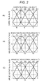
- a phase current waveform diagram when performing the sine wave energization to U-phase, V-phase, and W-phase is as illustrated in Fig. 2A , and there are phase differences of 120° among the U-phase current lu, the V-phase current Iv, and the W-phase current Iw each forming the sine waveform.
- the following Formula 2 holds among the phase currents lu, Iv, and Iw, the phase current peak value Ip, and the phase current electrical angle ⁇ i.
- the phase current peak value and electrical angle detecting unit 4 obtains the phase current peak value Ip and the phase current electrical angle ⁇ i by Formula 2 by utilizing the U-phase current lu, the V-phase current Iv, and the W-phase current Iw that are detected by the phase current detecting unit 2.
- Iu Ip ⁇ cos ⁇ i
- Iv Ip ⁇ cos ⁇ i - 2 / 3 ⁇
- Iw Ip ⁇ cos ⁇ i + 2 / 3 ⁇ ⁇
- An induced voltage peak value and electrical angle detecting unit 5 corresponding to the induced voltage peak value and electrical angle detecting unit detects an induced voltage peak value Ep and an induced voltage electrical angle ⁇ e (stator ⁇ coordinate system), based on the phase currents lu, Iv, and Iw detected by the phase current detecting unit 2, and the applied voltages Vu, Vv, and Vw detected by the applied voltage detecting unit 3.
- the detecting method is as follows. The detecting method is also described in detail in Reference 1.
- An induced voltage waveform diagram when performing the sine wave energization to U-phase, V-phase and W-phase is as illustrated in Fig. 2B , and there are phase differences of 120°among a U-phase induced voltage Eu, a V-phase induced voltage Ev, and a W-phase induced voltage Ew, each forming a sine waveform.
- the following Formula 3 holds among the induced voltages Eu, Ev, and Ew, the induced voltage peak value Ep, and the induced voltage electrical angle ⁇ e.
- Eu Ep ⁇ cos ⁇ e
- Ev Ep ⁇ cos ⁇ e - 2 / 3 ⁇
- Ew Ep ⁇ cos ⁇ e + 2 / 3 ⁇ ⁇
- the induced voltage peak value and electrical angle detecting unit 5 obtains the U-phase induced voltage Eu, the V-phase induced voltage Ev, and the W-phase induced voltage Ew from Formula 4, based on the U-phase current lu, the V-phase current Iv, and the W-phase current Iw detected by the phase current detecting unit 2, and the U-phase applied voltage Vu, the V-phase applied voltage Vv, and the W-phase applied voltage Vw detected by the applied voltage detecting unit 3, and obtains the induced voltage peak value Ep and the induced voltage electrical angle ⁇ e from Formula 3, based on the obtained U-phase induced voltage Eu, the V-phase induced voltage Ev, and the W-phase induced voltage Ew.
- a rotor position detecting unit 6 corresponding to the rotor position detecting unit detects a rotor position ⁇ m (an angle of d-axis with respect to ⁇ -axis), based on the phase current peak value Ip and the phase current electrical angle ⁇ i detected by the phase current peak value and electrical angle detecting unit 4, and the induced voltage peak value Ep and the induced voltage electrical angle ⁇ e detected by the induced voltage peak value and electrical angle detecting unit 5.
- the rotor position ⁇ m of the synchronous motor M is detected by using a rotor position calculation formula that includes the current electrical angle ⁇ i or the induced voltage electrical angle ⁇ e as a variable, and includes a current phase ⁇ or an induced voltage phase ⁇ obtained based on at least two of the current peak value Ip, the induced voltage peak value Ep, and the difference [ ⁇ e - ⁇ i] between the induced voltage electrical angle ⁇ e and the current electrical angle ⁇ i as a variable (see Reference 1 for details).
- a first detecting method of using a rotor position calculation formula including the phase current electrical angle ⁇ i, and the current phase ⁇ based on the phase current peak value Ip and [induced voltage electrical angle ⁇ e - phase current electrical angle ⁇ i] as a variable and a second detecting method of using a rotor position calculation formula including the induced voltage electrical angle ⁇ e, and an induced voltage phase ⁇ based on the phase current peak value Ip and [induced voltage electrical angle ⁇ e - phase current electrical angle ⁇ i] as a variable, will be described in detail.
- the rotor position calculation formula including the detected phase current electrical angle ⁇ i and the current phase ⁇ as variables is the following Formula 5.
- ⁇ m ⁇ i - ⁇ - 90 ⁇ °
- the current phase ⁇ in Formula 5 is selected by referring to a previously prepared data table using the phase current peak value Ip and [induced voltage electrical angle ⁇ e - phase current electrical angle ⁇ i] as parameters.
- the data table has been prepared as follows and stored in memory.
- Fig. 3 illustrates a motor vector diagram when the rotor of the synchronous motor M is rotating, and a relation among the applied voltage V (Vu to Vw), the current I (Iu to Iw), and the induced voltage E (Eu to Ew) is expressed by vectors in a d-q coordinate.
- the induced voltage E is expressed by [ ⁇ ].
- Vd is a d-axis component of the applied voltage V
- Vq is a q-axis component of the applied voltage V
- symbol Id is a d-axis component of the current I
- symbol Iq is a q-axis component of the current I
- symbol Ed is a d-axis component of the induced voltage E
- symbol Eq is a q-axis component of the induced voltage E.
- the voltage phase based on the q-axis is ⁇
- the current phase based on the q-axis is ⁇
- the induced voltage phase based on the q-axis is ⁇ .
- Formula 6 holds when the rotational speed of the rotor is set as ⁇
- Formula 7 holds when the value concerning ⁇ is transferred from the right side of Formula 6 to the left side thereof.
- the data table is created in advance based on holding of Formulas 6 and 7 under the motor vector diagram of Fig. 3 . That is, while progressively increasing the current phase ⁇ and the current I illustrated in the motor vector diagram within respective predetermined ranges, the current phase ⁇ when [induced voltage phase ⁇ - current phase ⁇ ] becomes a predetermined value is saved, to thereby create a data table of the current phase ⁇ in which the phase current peak value Ip corresponding to the current I, and [induced voltage electrical angle ⁇ e - phase current electrical angle ⁇ i] corresponding to [induced voltage phase ⁇ - current phase ⁇ ] are set as parameters.
- the voltage phase ⁇ , the current phase ⁇ , and the induced voltage phase ⁇ based on the motor vector diagram are obtained by using the d-axis inductance Ld and the q-axis inductance Lq intrinsic to the synchronous motor M.
- the current phase ⁇ when [induced voltage phase y - current phase ⁇ ] is 1°, 2°, 3°,... is saved.
- phase current peak value Ip corresponding to the current I
- [induced voltage electrical angle ⁇ e - phase current electrical angle ⁇ i] corresponding to [induced voltage phase ⁇ - current phase ⁇ ] is set as another parameter.
- the rotor position calculation formula including the detected induced voltage electrical angle ⁇ e and the induced voltage phase ⁇ as variables is the following Formula 8.
- ⁇ m ⁇ e - ⁇ - 90 ⁇ °
- the induced voltage phase ⁇ in Formula 8 is selected by setting the phase current peak value Ip and [induced voltage electrical angle ⁇ e - phase current electrical angle ⁇ i] as parameters and referring to the data table prepared in advance.
- the data table has been prepared as follows and stored in memory.
- the data table of this case is also created in advance based on holding of Formulas 6 and 7 under the motor vector diagram of Fig. 3 . That is, while progressively increasing the current phase ⁇ and the current I illustrated in the motor vector diagram within respective predetermined ranges, the induced voltage phase ⁇ when [induced voltage phase ⁇ - current phase ⁇ ] becomes a predetermined value is stored, to thereby create a data table of the induced voltage phase ⁇ in which the phase current peak value Ip corresponding to the current I and [induced voltage electrical angle ⁇ e - phase current electrical angle ⁇ i] corresponding to [induced voltage phase ⁇ - current phase ⁇ ] are set as parameters.
- the voltage phase ⁇ , the current phase ⁇ , and the induced voltage phase ⁇ based on the motor vector diagram are obtained by using the d-axis inductance Ld and the q-axis inductance Lq intrinsic to the synchronous motor M.
- the induced voltage phase ⁇ when [induced voltage ⁇ - phase current phase ⁇ ] is 1 °, 2°, 3°,... is saved.
- the data table of the induced voltage phase ⁇ is created in which the phase current peak value Ip corresponding to the current I is set as one parameter, and [induced voltage electrical angle ⁇ e - phase current electrical angle ⁇ i] corresponding to [induced voltage phase ⁇ - current phase ⁇ ] is set as another parameter.
- the rotor position detecting unit 6 configured to perform the above-described first and second detecting methods, since the rotor position ⁇ m is directly obtained by using the rotor position calculation formula described above, it is possible to accurately detect the rotor position ⁇ m in the position detecting operation. Furthermore, since the method of selecting the current phase ⁇ or the induced voltage phase ⁇ as one of the variables included in the rotor calculation formula from the data table prepared in advance is employed, a processing load is lower than a case of obtaining the current phase ⁇ or the induced voltage phase ⁇ by calculation each time. However, as long as the processing load may not be considered, it is also possible to calculate the variables by calculation each time.
- a data table that selects the current phase ⁇ or the induced voltage phase ⁇ by setting the induced voltage peak value Ep and [induced voltage electrical angle ⁇ e - phase current electrical angle ⁇ i] as parameters
- a data table that selects the current phase ⁇ or the induced voltage phase ⁇ by setting the phase current peak value Ip and the induced voltage peak value Ep as parameters or a data table that selects the current phase ⁇ or the induced voltage phase ⁇ by setting the phase current peak value Ip, the induced voltage peak value Ep, and [induced voltage electrical angle ⁇ e - phase current electrical angle ⁇ i] as parameters.
- the rotor position ⁇ m detected by the rotor position detecting unit 6 as described above is input to a rotational speed detecting unit 7 corresponding to the rotational speed detecting unit.
- the rotational speed detecting unit 7 detects the rotational speed ⁇ by d ⁇ m/dt based on the rotor position ⁇ m detected by the rotor position detecting unit 6.
- a filter equal to or slower than L/R is preferably adapted.
- a voltage instruction value setting unit 8 functioning as a voltage instruction value setting unit sets a voltage instruction value (voltage peak value) Vptarg of the applied voltage based on a command rotational speed included in an operation command to be input from the outside and the rotational speed ⁇ detected by the rotational speed detecting unit 7, and provides the voltage instruction value to the inverter driving unit 1. It is preferred that the response speed of the voltage instruction value Vptarg be set to responsiveness sufficiently slower than the filter used when calculating the rotational speed ⁇ for preventing oscillation between ⁇ and the Vptarg.
- an applied voltage electrical angle instruction value ⁇ vtarg as another instruction value provided to the inverter driving unit 1 is set according to a first setting method or a second setting method described below, by a voltage electrical angle instruction value setting unit 10 corresponding to the voltage electrical angle instruction value setting unit.
- the position detecting operation for controlling the current phase to the target phase is executed because of excellent motor efficiency. That is, in order to set the current phase to the target phase, the voltage electrical angle of the applied voltage is updated at every control period. In this case, especially in the transient state, since the response delay due to the L/R time constant (B portion of Formula 1) of the synchronous motor M illustrated in Formula 1 described above occurs until the current phase changes in response to a change in the voltage phase, when the variation width of the applied voltage electrical angle instruction value ⁇ vtarg is not adjusted in consideration of the response characteristics, the oscillation of the instruction value or the loss of synchronization occurs.
- the voltage electrical angle instruction value setting unit 10 illustrated below configured to perform the first setting method and the second setting method performs the computation considering the response characteristics.
- the applied voltages Vu, Vv, and Vw applied to the stator coil of the synchronous motor M are detected by the applied voltage detecting unit 3, and the phase currents lu, Iv, and Iw are detected by the phase current detecting unit 2.
- the current peak value Ip and the phase current electrical angle ⁇ i are detected by the phase current peak value and electrical angle detecting unit 4, and the induced voltage peak value Ep and the induced voltage electrical angle ⁇ e are detected by the induced voltage peak value and electrical angle detecting unit 5.
- the present applied voltage phase ⁇ is calculated based on the detected applied voltages Vu, Vv, and Vw.
- the present applied voltage phase ⁇ can be calculated in the following manner.
- phase applied voltage waveforms when performing the sine wave energization to U-phase, V-phase, and W-phase, as in the case of the phase current and the induced voltage described above, as illustrated in Fig. 2C , there are phase differences of 120° among the U-phase applied voltage current Vu, the V-phase voltage applied Vv, and the W-phase applied voltage Vw each forming a sine waveform.
- the following Formula 9 holds among the applied voltages Vu, Vv, and Vw of the respective phases, the applied voltage peak value Vp, and the applied voltage electrical angle ⁇ v.
- the voltage electrical angle instruction value setting unit 10 obtains the applied voltage peak value Vp and the applied voltage electrical angle ⁇ v by Formula 9 by using the U-phase applied voltage Vu, the V-phase applied voltage Vv, and the W-phase applied voltage Vw detected by the applied voltage detecting unit 3. This computation may be performed by the rotor position detecting unit 6 or the like.
- Vu Vp ⁇ cos ⁇ v
- Vv Vp ⁇ cos ⁇ v - 2 / 3 ⁇
- Vw Vp ⁇ cos ⁇ v + 2 / 3 ⁇ ⁇
- a target value setting unit 20 corresponding to the target value setting unit receives the current peak value Ip detected by the phase current peak value and electrical angle detecting unit 4 through the rotor position detecting unit 6, and calculates a target current phase ⁇ targ based on the present current peak value Ip.
- the present current phase ⁇ is calculated in the rotor position detecting unit 6, the current peak value Ip and the present q-axis current Iq (q-axis component of the current peak value Ip) presumed from the current phase ⁇ may be used for a calculation of the target current phase ⁇ targ.
- the voltage electrical angle instruction value setting unit 10 computes a difference between the calculated present applied voltage phase ⁇ and the target applied voltage phase ⁇ targ, and at this time, calculates the change angle ⁇ v by performing a correction by the response time constant L/R of the synchronous motor M stored in advance.
- the response time constant to be used here may be a value obtained by computing the portion B of Formula 1 described above, based on Ld and Lq known as the motor parameters, and Id and Iq that can be calculated from the current peak value IP and the current phase ⁇ .
- symbol ⁇ t in the formula is a control period.
- ⁇ vtarg ⁇ vtarg - 1 + ⁇ ⁇ ⁇ t + ⁇ targ - ⁇ ⁇ L / R
- the applied voltage electrical angle instruction value ⁇ vtarg is updated, while maintaining the suitable response speed according to the response characteristics of the synchronous motor M.
- the computation using the present applied voltage phase ⁇ and the target applied voltage phase ⁇ targ can be replaced by a computation using the calculated present applied voltage electrical angle ⁇ v and a target applied voltage electrical angle ⁇ v' based on the target applied voltage phase ⁇ targ.
- [ ⁇ targ - ⁇ ] in Formula 13 is replaced by [ ⁇ v' - ⁇ v].
- J ⁇ Ki/Kt is the response delay coefficient due to inertia
- symbol J is inertia of the load (kgm)
- symbol Kt is a torque constant (Nm/A) known as a motor parameter.
- V is an applied voltage (V)
- symbol Ke is an induced voltage constant (V/(rad/sec))
- symbol ⁇ is a rotational speed (rad/sec).
- the J ⁇ Ki/Kt is determined in the following manner.
- the synchronous motor M exhibits characteristics represented by the following Formula 16 in regard to the current I (A).
- ⁇ m ⁇ m 0 - Ki ⁇ I
- a change angle ⁇ v of the applied voltage electrical angle instruction value ⁇ vtarg is calculated.
- V ⁇ ⁇ ⁇ between the flux linkage ⁇ and the applied voltage V
- the applied voltage is controlled to increase the rotational speed ⁇ by an amount equivalent to the amount of this flux linkage variation ⁇ , as a result, the current phase reaches the target value.
- the applied voltage electrical angle instruction value ⁇ vtarg is updated, while maintaining the suitable response speed according to the response characteristics of the synchronous motor M.
- ( ⁇ targ - ⁇ )/ ⁇ is indirectly calculated from the d-axis current Id.
- the applied voltages Vu, Vv, and Vw to be applied to the stator coil of the synchronous motor M are detected by the applied voltage detecting unit 3, and the phase currents lu, Iv, and Iw are detected by the phase current detecting unit 2.
- the current peak value Ip and the phase current electrical angle ⁇ i are detected by the phase current peak value and electrical angle detecting unit 4, and the induced voltage peak value Ep and the induced voltage electrical angle ⁇ e are detected by the induced voltage peak value and electrical angle detecting unit 5.
- the rotor position ⁇ m is detected by the rotor position detecting unit 6.
- the target value setting unit 20 calculates a target d-axis current Idtarg based on the current peak value Ip (or the q-axis current Ip is also possible in the same manner as described above) that is input from the rotor position detecting unit 6.
- the target value setting unit 20 has a data table created in advance from the known parameters of the synchronous motor M and stored in the memory, and the data table includes a target d-axis current Idtarg corresponding to an optimal current lead angle (target current phase ⁇ targ) at which the efficiency is maximized or the torque is maximized under the same current, for each value (for example, for each 1A) of the current peak value Ip (or Iq).
- the target value setting unit 20 selects the target d-axis current Idtarg corresponding to the present current peak value Ip (or Iq) from the data table, and inputs the target d-axis current Idtarg to the voltage electrical angle instruction value setting unit 10.
- the voltage electrical angle instruction value setting unit 10 receives the present d-axis current Id from the rotor position detecting unit 6, and calculates the d-axis current difference ⁇ Id between the present d-axis current Id and the target d-axis current Idtarg. Since the current phase ⁇ is detected by the rotor position detecting unit 6, the present d-axis current Id can be calculated from the current peak value Ip and the current phase ⁇ . This operation may be performed by the rotor position detecting unit 6, or may be performed by the voltage electrical angle instruction value setting unit 10 that receives the present current peak value Ip and the current phase ⁇ from the rotor position detecting unit 6.
- the voltage electrical angle instruction value setting unit 10 calculates the amount of flux linkage variation ⁇ of the rotor corresponding to the d-axis current difference ⁇ Id, and calculates the change angle ⁇ v based on the amount of flux linkage variation ⁇ and the rotational speed ⁇ detected by the rotational speed detecting unit 7.
- Fig. 4 illustrates an internal block diagram of the voltage electrical angle instruction value setting unit 10 according to the second setting method.
- a unit variation amount ⁇ /A (%: for example, 70/4096) of the flux linkage ⁇ when the d-axis current Id changes by 1A is stored as one of the motor parameters, and in a multiplying unit 13, the unit variation amount ⁇ /A and the d-axis current difference ⁇ Id are computed, and the amount of the flux linkage variation ⁇ corresponding to the d-axis current difference ⁇ Id is calculated.
- the amount of the linkage flux variation ⁇ is input to a multiplying unit 14, and a computation is carried out with the present rotational speed ⁇ that is input from the rotational speed detecting unit 7 and the control period ⁇ t.
- the present rotational speed ⁇ at this time is clamped at the maximum value according to the response time constant L/R by a clamp portion 15.
- ⁇ electric angle rotational number
- ⁇ is clamped by 1/(L/R) Hz.
- the change angle ⁇ v ⁇ ⁇ ⁇ ⁇ ⁇ t that is output from the multiplying unit 14 is input to an inertia correcting unit 16.
- the inertia correcting unit 16 corrects the change angle ⁇ v using the response delay coefficient J ⁇ Ki/Kt considering the inertia of the synchronous motor M.
- the change angle ⁇ v ⁇ J ⁇ Ki/Kt after the inertia correction is input to an adding unit 17.
- the adding unit 17 carries out a computation with ⁇ ⁇ ⁇ t obtained by multiplying the present rotational speed ⁇ by the control period ⁇ t using a multiplying unit 18, the applied voltage electrical angle instruction value ⁇ vtarg (-1) of the previous, that is, once before control cycle, and the change angle ⁇ v ⁇ J ⁇ Ki/Kt after the inertia correction, and outputs a new applied voltage electrical angle instruction value ⁇ vtarg expressed by the following Formula 21.
- ⁇ vtarg ⁇ vtarg - 1 + ⁇ ⁇ ⁇ t + ⁇ v ⁇ J ⁇ Ki / Kt
- the applied voltage electrical angle instruction value ⁇ vtarg in a case of omitting the inertia correcting unit 16 is expressed by the following Formula 22.
- ⁇ vtarg ⁇ vtarg - 1 + ⁇ ⁇ ⁇ t + ⁇ v
Applications Claiming Priority (2)
| Application Number | Priority Date | Filing Date | Title |
|---|---|---|---|
| JP2011104878A JP5748051B2 (ja) | 2011-05-10 | 2011-05-10 | 同期モータの印加電圧電気角設定方法とモータ制御装置 |
| PCT/JP2012/060868 WO2012153624A1 (ja) | 2011-05-10 | 2012-04-23 | 同期モータの印加電圧電気角設定方法とモータ制御装置 |
Publications (3)
| Publication Number | Publication Date |
|---|---|
| EP2696495A1 true EP2696495A1 (de) | 2014-02-12 |
| EP2696495A4 EP2696495A4 (de) | 2015-04-01 |
| EP2696495B1 EP2696495B1 (de) | 2016-08-10 |
Family
ID=47139110
Family Applications (1)
| Application Number | Title | Priority Date | Filing Date |
|---|---|---|---|
| EP12781562.9A Active EP2696495B1 (de) | 2011-05-10 | 2012-04-23 | Verfahren zur einstellung des winkels einer angewandten elektrischen spannung für einen synchronmotor und motorsteuerungsvorrichtung |
Country Status (5)
| Country | Link |
|---|---|
| US (1) | US9184683B2 (de) |
| EP (1) | EP2696495B1 (de) |
| JP (1) | JP5748051B2 (de) |
| CN (1) | CN103503304B (de) |
| WO (1) | WO2012153624A1 (de) |
Families Citing this family (13)
| Publication number | Priority date | Publication date | Assignee | Title |
|---|---|---|---|---|
| WO2014056695A2 (de) * | 2012-10-10 | 2014-04-17 | Maschinenfabrik Reinhausen Gmbh | Verfahren zur spannungsregelung eines transformators |
| CN105375838B (zh) * | 2015-11-12 | 2018-02-06 | 珠海格力节能环保制冷技术研究中心有限公司 | 电机相位的控制电路和方法 |
| JP6633399B2 (ja) * | 2016-01-27 | 2020-01-22 | サンデン・オートモーティブコンポーネント株式会社 | モータ制御装置 |
| JP6646484B2 (ja) * | 2016-03-15 | 2020-02-14 | サンデン・オートモーティブコンポーネント株式会社 | モータ制御装置 |
| EP3242168B1 (de) * | 2016-05-04 | 2018-11-21 | ETA SA Manufacture Horlogère Suisse | Elektromechanisches uhrwerk, das eine vorrichtung zur erfassung der winkelposition eines rads umfasst |
| MY197536A (en) * | 2016-12-26 | 2023-06-21 | Panasonic Ip Man Co Ltd | Power generation device |
| JP7111471B2 (ja) * | 2018-01-24 | 2022-08-02 | マブチモーター株式会社 | 制御装置 |
| JP6936171B2 (ja) * | 2018-02-28 | 2021-09-15 | サンデン・オートモーティブコンポーネント株式会社 | モータ制御装置 |
| JP6805197B2 (ja) * | 2018-03-01 | 2020-12-23 | 株式会社東芝 | モータ制御用集積回路 |
| WO2019216171A1 (ja) * | 2018-05-07 | 2019-11-14 | パナソニックIpマネジメント株式会社 | 駆動用機器、及び駆動システム |
| CN108710089B (zh) * | 2018-05-16 | 2021-01-22 | 中国神华能源股份有限公司 | 用于轨道电路电源的相位监测方法及相位检测装置 |
| JP7163223B2 (ja) | 2019-03-14 | 2022-10-31 | 株式会社東芝 | 駆動装置、駆動システム、及び、電動機の駆動方法 |
| JP2022059935A (ja) * | 2020-10-02 | 2022-04-14 | 日本電産株式会社 | 電気角推定装置、モータ、掃除機、及び電気角推定方法 |
Citations (1)
| Publication number | Priority date | Publication date | Assignee | Title |
|---|---|---|---|---|
| JP2011010438A (ja) * | 2009-06-25 | 2011-01-13 | Sanden Corp | モータ制御装置 |
Family Cites Families (13)
| Publication number | Priority date | Publication date | Assignee | Title |
|---|---|---|---|---|
| US4088934A (en) * | 1976-10-04 | 1978-05-09 | General Electric Company | Means for stabilizing an a-c electric motor drive system |
| US5650708A (en) | 1992-12-08 | 1997-07-22 | Nippondenso Co., Ltd. | Inverter control apparatus using a two-phase modulation method |
| JP3677804B2 (ja) * | 1994-03-10 | 2005-08-03 | 株式会社デンソー | インバータ制御装置 |
| US6137258A (en) * | 1998-10-26 | 2000-10-24 | General Electric Company | System for speed-sensorless control of an induction machine |
| JP2000278987A (ja) * | 1999-03-19 | 2000-10-06 | Toshiba Corp | インバータ装置 |
| JP3454210B2 (ja) * | 1999-11-30 | 2003-10-06 | 株式会社日立製作所 | 同期モータの位置センサレス制御方法 |
| JP4067949B2 (ja) * | 2002-12-03 | 2008-03-26 | サンデン株式会社 | モータ制御装置 |
| JP4473076B2 (ja) * | 2004-08-30 | 2010-06-02 | 株式会社日立産機システム | リニア同期電動機の制御方法及び装置 |
| EP1882159A1 (de) * | 2005-05-11 | 2008-01-30 | Toyota Jidosha Kabushiki Kaisha | Elektrische dreheinrichtung - antriebseinheit damit |
| JP4716118B2 (ja) * | 2006-03-29 | 2011-07-06 | 株式会社ジェイテクト | モータ制御装置 |
| EP2642658B1 (de) * | 2007-09-25 | 2018-08-29 | Mitsubishi Electric Corporation | Steuerung für einen Elektromotor |
| JP5228436B2 (ja) * | 2007-10-18 | 2013-07-03 | 株式会社安川電機 | モータ制御装置とその制御方法 |
| JP5838038B2 (ja) * | 2011-04-22 | 2015-12-24 | サンデンホールディングス株式会社 | モータ制御装置 |
-
2011
- 2011-05-10 JP JP2011104878A patent/JP5748051B2/ja active Active
-
2012
- 2012-04-23 EP EP12781562.9A patent/EP2696495B1/de active Active
- 2012-04-23 CN CN201280022294.7A patent/CN103503304B/zh active Active
- 2012-04-23 US US14/115,194 patent/US9184683B2/en active Active
- 2012-04-23 WO PCT/JP2012/060868 patent/WO2012153624A1/ja active Application Filing
Patent Citations (1)
| Publication number | Priority date | Publication date | Assignee | Title |
|---|---|---|---|---|
| JP2011010438A (ja) * | 2009-06-25 | 2011-01-13 | Sanden Corp | モータ制御装置 |
Non-Patent Citations (1)
| Title |
|---|
| See also references of WO2012153624A1 * |
Also Published As
| Publication number | Publication date |
|---|---|
| EP2696495A4 (de) | 2015-04-01 |
| JP5748051B2 (ja) | 2015-07-15 |
| CN103503304A (zh) | 2014-01-08 |
| US20140070745A1 (en) | 2014-03-13 |
| CN103503304B (zh) | 2017-02-15 |
| JP2012239250A (ja) | 2012-12-06 |
| EP2696495B1 (de) | 2016-08-10 |
| WO2012153624A1 (ja) | 2012-11-15 |
| US9184683B2 (en) | 2015-11-10 |
Similar Documents
| Publication | Publication Date | Title |
|---|---|---|
| EP2696495B1 (de) | Verfahren zur einstellung des winkels einer angewandten elektrischen spannung für einen synchronmotor und motorsteuerungsvorrichtung | |
| JP5838038B2 (ja) | モータ制御装置 | |
| EP2662977B1 (de) | Motorsteuerung | |
| US9035581B2 (en) | Motor control device | |
| EP2448105B1 (de) | Motorsteuervorrichtung | |
| EP2662976B1 (de) | Motorsteuervorrichtung | |
| US11396092B2 (en) | Electric power tool provided with motor controller controlling motor including limiter for limitting current contributing to torque generation | |
| EP1821402A1 (de) | Motorsteuervorrichtung und Motorsteuerverfahren | |
| US10516354B2 (en) | Motor control device | |
| JP2020039227A (ja) | 電動機の駆動装置 | |
| WO2017130842A1 (ja) | モータ制御装置 | |
| CN111742485B (zh) | 电动机控制装置 | |
| JP6936172B2 (ja) | モータ制御装置 |
Legal Events
| Date | Code | Title | Description |
|---|---|---|---|
| PUAI | Public reference made under article 153(3) epc to a published international application that has entered the european phase |
Free format text: ORIGINAL CODE: 0009012 |
|
| 17P | Request for examination filed |
Effective date: 20131104 |
|
| AK | Designated contracting states |
Kind code of ref document: A1 Designated state(s): AL AT BE BG CH CY CZ DE DK EE ES FI FR GB GR HR HU IE IS IT LI LT LU LV MC MK MT NL NO PL PT RO RS SE SI SK SM TR |
|
| DAX | Request for extension of the european patent (deleted) | ||
| RIC1 | Information provided on ipc code assigned before grant |
Ipc: H02P 6/16 20060101AFI20150128BHEP |
|
| RIC1 | Information provided on ipc code assigned before grant |
Ipc: H02P 6/16 20060101AFI20150203BHEP |
|
| RA4 | Supplementary search report drawn up and despatched (corrected) |
Effective date: 20150304 |
|
| RIC1 | Information provided on ipc code assigned before grant |
Ipc: H02P 6/16 20060101AFI20150226BHEP Ipc: H02P 27/06 20060101ALI20150226BHEP Ipc: H02P 21/00 20060101ALI20150226BHEP |
|
| GRAP | Despatch of communication of intention to grant a patent |
Free format text: ORIGINAL CODE: EPIDOSNIGR1 |
|
| INTG | Intention to grant announced |
Effective date: 20160224 |
|
| RAP1 | Party data changed (applicant data changed or rights of an application transferred) |
Owner name: SANDEN HOLDINGS CORPORATION |
|
| GRAS | Grant fee paid |
Free format text: ORIGINAL CODE: EPIDOSNIGR3 |
|
| GRAA | (expected) grant |
Free format text: ORIGINAL CODE: 0009210 |
|
| AK | Designated contracting states |
Kind code of ref document: B1 Designated state(s): AL AT BE BG CH CY CZ DE DK EE ES FI FR GB GR HR HU IE IS IT LI LT LU LV MC MK MT NL NO PL PT RO RS SE SI SK SM TR |
|
| REG | Reference to a national code |
Ref country code: GB Ref legal event code: FG4D |
|
| REG | Reference to a national code |
Ref country code: CH Ref legal event code: EP Ref country code: AT Ref legal event code: REF Ref document number: 819840 Country of ref document: AT Kind code of ref document: T Effective date: 20160815 |
|
| REG | Reference to a national code |
Ref country code: IE Ref legal event code: FG4D |
|
| REG | Reference to a national code |
Ref country code: DE Ref legal event code: R096 Ref document number: 602012021563 Country of ref document: DE |
|
| REG | Reference to a national code |
Ref country code: LT Ref legal event code: MG4D |
|
| REG | Reference to a national code |
Ref country code: NL Ref legal event code: MP Effective date: 20160810 |
|
| REG | Reference to a national code |
Ref country code: AT Ref legal event code: MK05 Ref document number: 819840 Country of ref document: AT Kind code of ref document: T Effective date: 20160810 |
|
| PG25 | Lapsed in a contracting state [announced via postgrant information from national office to epo] |
Ref country code: HR Free format text: LAPSE BECAUSE OF FAILURE TO SUBMIT A TRANSLATION OF THE DESCRIPTION OR TO PAY THE FEE WITHIN THE PRESCRIBED TIME-LIMIT Effective date: 20160810 Ref country code: FI Free format text: LAPSE BECAUSE OF FAILURE TO SUBMIT A TRANSLATION OF THE DESCRIPTION OR TO PAY THE FEE WITHIN THE PRESCRIBED TIME-LIMIT Effective date: 20160810 Ref country code: RS Free format text: LAPSE BECAUSE OF FAILURE TO SUBMIT A TRANSLATION OF THE DESCRIPTION OR TO PAY THE FEE WITHIN THE PRESCRIBED TIME-LIMIT Effective date: 20160810 Ref country code: LT Free format text: LAPSE BECAUSE OF FAILURE TO SUBMIT A TRANSLATION OF THE DESCRIPTION OR TO PAY THE FEE WITHIN THE PRESCRIBED TIME-LIMIT Effective date: 20160810 Ref country code: NO Free format text: LAPSE BECAUSE OF FAILURE TO SUBMIT A TRANSLATION OF THE DESCRIPTION OR TO PAY THE FEE WITHIN THE PRESCRIBED TIME-LIMIT Effective date: 20161110 Ref country code: IT Free format text: LAPSE BECAUSE OF FAILURE TO SUBMIT A TRANSLATION OF THE DESCRIPTION OR TO PAY THE FEE WITHIN THE PRESCRIBED TIME-LIMIT Effective date: 20160810 Ref country code: IS Free format text: LAPSE BECAUSE OF FAILURE TO SUBMIT A TRANSLATION OF THE DESCRIPTION OR TO PAY THE FEE WITHIN THE PRESCRIBED TIME-LIMIT Effective date: 20161210 Ref country code: NL Free format text: LAPSE BECAUSE OF FAILURE TO SUBMIT A TRANSLATION OF THE DESCRIPTION OR TO PAY THE FEE WITHIN THE PRESCRIBED TIME-LIMIT Effective date: 20160810 |
|
| PG25 | Lapsed in a contracting state [announced via postgrant information from national office to epo] |
Ref country code: AT Free format text: LAPSE BECAUSE OF FAILURE TO SUBMIT A TRANSLATION OF THE DESCRIPTION OR TO PAY THE FEE WITHIN THE PRESCRIBED TIME-LIMIT Effective date: 20160810 Ref country code: ES Free format text: LAPSE BECAUSE OF FAILURE TO SUBMIT A TRANSLATION OF THE DESCRIPTION OR TO PAY THE FEE WITHIN THE PRESCRIBED TIME-LIMIT Effective date: 20160810 Ref country code: PT Free format text: LAPSE BECAUSE OF FAILURE TO SUBMIT A TRANSLATION OF THE DESCRIPTION OR TO PAY THE FEE WITHIN THE PRESCRIBED TIME-LIMIT Effective date: 20161212 Ref country code: SE Free format text: LAPSE BECAUSE OF FAILURE TO SUBMIT A TRANSLATION OF THE DESCRIPTION OR TO PAY THE FEE WITHIN THE PRESCRIBED TIME-LIMIT Effective date: 20160810 Ref country code: GR Free format text: LAPSE BECAUSE OF FAILURE TO SUBMIT A TRANSLATION OF THE DESCRIPTION OR TO PAY THE FEE WITHIN THE PRESCRIBED TIME-LIMIT Effective date: 20161111 Ref country code: LV Free format text: LAPSE BECAUSE OF FAILURE TO SUBMIT A TRANSLATION OF THE DESCRIPTION OR TO PAY THE FEE WITHIN THE PRESCRIBED TIME-LIMIT Effective date: 20160810 Ref country code: PL Free format text: LAPSE BECAUSE OF FAILURE TO SUBMIT A TRANSLATION OF THE DESCRIPTION OR TO PAY THE FEE WITHIN THE PRESCRIBED TIME-LIMIT Effective date: 20160810 |
|
| PG25 | Lapsed in a contracting state [announced via postgrant information from national office to epo] |
Ref country code: RO Free format text: LAPSE BECAUSE OF FAILURE TO SUBMIT A TRANSLATION OF THE DESCRIPTION OR TO PAY THE FEE WITHIN THE PRESCRIBED TIME-LIMIT Effective date: 20160810 Ref country code: EE Free format text: LAPSE BECAUSE OF FAILURE TO SUBMIT A TRANSLATION OF THE DESCRIPTION OR TO PAY THE FEE WITHIN THE PRESCRIBED TIME-LIMIT Effective date: 20160810 |
|
| REG | Reference to a national code |
Ref country code: DE Ref legal event code: R097 Ref document number: 602012021563 Country of ref document: DE |
|
| PG25 | Lapsed in a contracting state [announced via postgrant information from national office to epo] |
Ref country code: SM Free format text: LAPSE BECAUSE OF FAILURE TO SUBMIT A TRANSLATION OF THE DESCRIPTION OR TO PAY THE FEE WITHIN THE PRESCRIBED TIME-LIMIT Effective date: 20160810 Ref country code: BG Free format text: LAPSE BECAUSE OF FAILURE TO SUBMIT A TRANSLATION OF THE DESCRIPTION OR TO PAY THE FEE WITHIN THE PRESCRIBED TIME-LIMIT Effective date: 20161110 Ref country code: BE Free format text: LAPSE BECAUSE OF FAILURE TO SUBMIT A TRANSLATION OF THE DESCRIPTION OR TO PAY THE FEE WITHIN THE PRESCRIBED TIME-LIMIT Effective date: 20160810 Ref country code: DK Free format text: LAPSE BECAUSE OF FAILURE TO SUBMIT A TRANSLATION OF THE DESCRIPTION OR TO PAY THE FEE WITHIN THE PRESCRIBED TIME-LIMIT Effective date: 20160810 Ref country code: CZ Free format text: LAPSE BECAUSE OF FAILURE TO SUBMIT A TRANSLATION OF THE DESCRIPTION OR TO PAY THE FEE WITHIN THE PRESCRIBED TIME-LIMIT Effective date: 20160810 Ref country code: SK Free format text: LAPSE BECAUSE OF FAILURE TO SUBMIT A TRANSLATION OF THE DESCRIPTION OR TO PAY THE FEE WITHIN THE PRESCRIBED TIME-LIMIT Effective date: 20160810 |
|
| PLBE | No opposition filed within time limit |
Free format text: ORIGINAL CODE: 0009261 |
|
| STAA | Information on the status of an ep patent application or granted ep patent |
Free format text: STATUS: NO OPPOSITION FILED WITHIN TIME LIMIT |
|
| 26N | No opposition filed |
Effective date: 20170511 |
|
| PG25 | Lapsed in a contracting state [announced via postgrant information from national office to epo] |
Ref country code: SI Free format text: LAPSE BECAUSE OF FAILURE TO SUBMIT A TRANSLATION OF THE DESCRIPTION OR TO PAY THE FEE WITHIN THE PRESCRIBED TIME-LIMIT Effective date: 20160810 |
|
| REG | Reference to a national code |
Ref country code: CH Ref legal event code: PL |
|
| GBPC | Gb: european patent ceased through non-payment of renewal fee |
Effective date: 20170423 |
|
| REG | Reference to a national code |
Ref country code: IE Ref legal event code: MM4A |
|
| REG | Reference to a national code |
Ref country code: FR Ref legal event code: ST Effective date: 20171229 |
|
| PG25 | Lapsed in a contracting state [announced via postgrant information from national office to epo] |
Ref country code: MC Free format text: LAPSE BECAUSE OF FAILURE TO SUBMIT A TRANSLATION OF THE DESCRIPTION OR TO PAY THE FEE WITHIN THE PRESCRIBED TIME-LIMIT Effective date: 20160810 Ref country code: FR Free format text: LAPSE BECAUSE OF NON-PAYMENT OF DUE FEES Effective date: 20170502 |
|
| PG25 | Lapsed in a contracting state [announced via postgrant information from national office to epo] |
Ref country code: CH Free format text: LAPSE BECAUSE OF NON-PAYMENT OF DUE FEES Effective date: 20170430 Ref country code: LI Free format text: LAPSE BECAUSE OF NON-PAYMENT OF DUE FEES Effective date: 20170430 Ref country code: GB Free format text: LAPSE BECAUSE OF NON-PAYMENT OF DUE FEES Effective date: 20170423 Ref country code: LU Free format text: LAPSE BECAUSE OF NON-PAYMENT OF DUE FEES Effective date: 20170423 |
|
| PG25 | Lapsed in a contracting state [announced via postgrant information from national office to epo] |
Ref country code: IE Free format text: LAPSE BECAUSE OF NON-PAYMENT OF DUE FEES Effective date: 20170423 |
|
| PG25 | Lapsed in a contracting state [announced via postgrant information from national office to epo] |
Ref country code: MT Free format text: LAPSE BECAUSE OF NON-PAYMENT OF DUE FEES Effective date: 20170423 |
|
| PG25 | Lapsed in a contracting state [announced via postgrant information from national office to epo] |
Ref country code: AL Free format text: LAPSE BECAUSE OF FAILURE TO SUBMIT A TRANSLATION OF THE DESCRIPTION OR TO PAY THE FEE WITHIN THE PRESCRIBED TIME-LIMIT Effective date: 20160810 |
|
| PG25 | Lapsed in a contracting state [announced via postgrant information from national office to epo] |
Ref country code: HU Free format text: LAPSE BECAUSE OF FAILURE TO SUBMIT A TRANSLATION OF THE DESCRIPTION OR TO PAY THE FEE WITHIN THE PRESCRIBED TIME-LIMIT; INVALID AB INITIO Effective date: 20120423 |
|
| PG25 | Lapsed in a contracting state [announced via postgrant information from national office to epo] |
Ref country code: CY Free format text: LAPSE BECAUSE OF NON-PAYMENT OF DUE FEES Effective date: 20160810 |
|
| PG25 | Lapsed in a contracting state [announced via postgrant information from national office to epo] |
Ref country code: MK Free format text: LAPSE BECAUSE OF FAILURE TO SUBMIT A TRANSLATION OF THE DESCRIPTION OR TO PAY THE FEE WITHIN THE PRESCRIBED TIME-LIMIT Effective date: 20160810 |
|
| PG25 | Lapsed in a contracting state [announced via postgrant information from national office to epo] |
Ref country code: TR Free format text: LAPSE BECAUSE OF FAILURE TO SUBMIT A TRANSLATION OF THE DESCRIPTION OR TO PAY THE FEE WITHIN THE PRESCRIBED TIME-LIMIT Effective date: 20160810 |
|
| REG | Reference to a national code |
Ref country code: DE Ref legal event code: R081 Ref document number: 602012021563 Country of ref document: DE Owner name: SANDEN CORPORATION, ISESAKI-SHI, JP Free format text: FORMER OWNER: SANDEN HOLDINGS CORP., LSESAKI-SHI, GUNMA, JP |
|
| PGFP | Annual fee paid to national office [announced via postgrant information from national office to epo] |
Ref country code: DE Payment date: 20230321 Year of fee payment: 12 |