EP2690741B1 - Adaptateur, et véhicule ainsi que procédé permettant de fournir de l'énergie à l'aide de celui-ci - Google Patents
Adaptateur, et véhicule ainsi que procédé permettant de fournir de l'énergie à l'aide de celui-ci Download PDFInfo
- Publication number
- EP2690741B1 EP2690741B1 EP11861454.4A EP11861454A EP2690741B1 EP 2690741 B1 EP2690741 B1 EP 2690741B1 EP 11861454 A EP11861454 A EP 11861454A EP 2690741 B1 EP2690741 B1 EP 2690741B1
- Authority
- EP
- European Patent Office
- Prior art keywords
- power
- charging cable
- adapter
- signal
- vehicle
- Prior art date
- Legal status (The legal status is an assumption and is not a legal conclusion. Google has not performed a legal analysis and makes no representation as to the accuracy of the status listed.)
- Not-in-force
Links
- 238000000034 method Methods 0.000 title claims description 68
- 230000007274 generation of a signal involved in cell-cell signaling Effects 0.000 claims description 40
- 238000006243 chemical reaction Methods 0.000 claims description 34
- 230000004044 response Effects 0.000 claims description 12
- 230000005540 biological transmission Effects 0.000 claims description 5
- 230000008859 change Effects 0.000 claims description 5
- 230000008569 process Effects 0.000 description 60
- 230000010355 oscillation Effects 0.000 description 54
- 238000010586 diagram Methods 0.000 description 25
- 230000003247 decreasing effect Effects 0.000 description 21
- 238000012840 feeding operation Methods 0.000 description 11
- 230000004048 modification Effects 0.000 description 9
- 238000012986 modification Methods 0.000 description 9
- 239000000872 buffer Substances 0.000 description 7
- 238000001514 detection method Methods 0.000 description 6
- 239000003990 capacitor Substances 0.000 description 5
- 101150049032 ACL1 gene Proteins 0.000 description 4
- 101100448894 Arabidopsis thaliana GLR3.1 gene Proteins 0.000 description 4
- 101100054598 Hordeum vulgare ACL1.2 gene Proteins 0.000 description 4
- 101150023061 acpP gene Proteins 0.000 description 4
- 238000010248 power generation Methods 0.000 description 4
- 239000000446 fuel Substances 0.000 description 2
- 230000001172 regenerating effect Effects 0.000 description 2
- HBBGRARXTFLTSG-UHFFFAOYSA-N Lithium ion Chemical compound [Li+] HBBGRARXTFLTSG-UHFFFAOYSA-N 0.000 description 1
- 239000002253 acid Substances 0.000 description 1
- 230000015556 catabolic process Effects 0.000 description 1
- 238000002485 combustion reaction Methods 0.000 description 1
- 238000006731 degradation reaction Methods 0.000 description 1
- 230000001747 exhibiting effect Effects 0.000 description 1
- 229910001416 lithium ion Inorganic materials 0.000 description 1
- 230000007246 mechanism Effects 0.000 description 1
- 229910052987 metal hydride Inorganic materials 0.000 description 1
- 238000002360 preparation method Methods 0.000 description 1
- 238000011144 upstream manufacturing Methods 0.000 description 1
Images


Classifications
-
- B—PERFORMING OPERATIONS; TRANSPORTING
- B60—VEHICLES IN GENERAL
- B60L—PROPULSION OF ELECTRICALLY-PROPELLED VEHICLES; SUPPLYING ELECTRIC POWER FOR AUXILIARY EQUIPMENT OF ELECTRICALLY-PROPELLED VEHICLES; ELECTRODYNAMIC BRAKE SYSTEMS FOR VEHICLES IN GENERAL; MAGNETIC SUSPENSION OR LEVITATION FOR VEHICLES; MONITORING OPERATING VARIABLES OF ELECTRICALLY-PROPELLED VEHICLES; ELECTRIC SAFETY DEVICES FOR ELECTRICALLY-PROPELLED VEHICLES
- B60L53/00—Methods of charging batteries, specially adapted for electric vehicles; Charging stations or on-board charging equipment therefor; Exchange of energy storage elements in electric vehicles
- B60L53/60—Monitoring or controlling charging stations
- B60L53/68—Off-site monitoring or control, e.g. remote control
-
- B—PERFORMING OPERATIONS; TRANSPORTING
- B60—VEHICLES IN GENERAL
- B60L—PROPULSION OF ELECTRICALLY-PROPELLED VEHICLES; SUPPLYING ELECTRIC POWER FOR AUXILIARY EQUIPMENT OF ELECTRICALLY-PROPELLED VEHICLES; ELECTRODYNAMIC BRAKE SYSTEMS FOR VEHICLES IN GENERAL; MAGNETIC SUSPENSION OR LEVITATION FOR VEHICLES; MONITORING OPERATING VARIABLES OF ELECTRICALLY-PROPELLED VEHICLES; ELECTRIC SAFETY DEVICES FOR ELECTRICALLY-PROPELLED VEHICLES
- B60L3/00—Electric devices on electrically-propelled vehicles for safety purposes; Monitoring operating variables, e.g. speed, deceleration or energy consumption
- B60L3/0023—Detecting, eliminating, remedying or compensating for drive train abnormalities, e.g. failures within the drive train
- B60L3/0069—Detecting, eliminating, remedying or compensating for drive train abnormalities, e.g. failures within the drive train relating to the isolation, e.g. ground fault or leak current
-
- B—PERFORMING OPERATIONS; TRANSPORTING
- B60—VEHICLES IN GENERAL
- B60L—PROPULSION OF ELECTRICALLY-PROPELLED VEHICLES; SUPPLYING ELECTRIC POWER FOR AUXILIARY EQUIPMENT OF ELECTRICALLY-PROPELLED VEHICLES; ELECTRODYNAMIC BRAKE SYSTEMS FOR VEHICLES IN GENERAL; MAGNETIC SUSPENSION OR LEVITATION FOR VEHICLES; MONITORING OPERATING VARIABLES OF ELECTRICALLY-PROPELLED VEHICLES; ELECTRIC SAFETY DEVICES FOR ELECTRICALLY-PROPELLED VEHICLES
- B60L3/00—Electric devices on electrically-propelled vehicles for safety purposes; Monitoring operating variables, e.g. speed, deceleration or energy consumption
- B60L3/04—Cutting off the power supply under fault conditions
-
- B—PERFORMING OPERATIONS; TRANSPORTING
- B60—VEHICLES IN GENERAL
- B60L—PROPULSION OF ELECTRICALLY-PROPELLED VEHICLES; SUPPLYING ELECTRIC POWER FOR AUXILIARY EQUIPMENT OF ELECTRICALLY-PROPELLED VEHICLES; ELECTRODYNAMIC BRAKE SYSTEMS FOR VEHICLES IN GENERAL; MAGNETIC SUSPENSION OR LEVITATION FOR VEHICLES; MONITORING OPERATING VARIABLES OF ELECTRICALLY-PROPELLED VEHICLES; ELECTRIC SAFETY DEVICES FOR ELECTRICALLY-PROPELLED VEHICLES
- B60L50/00—Electric propulsion with power supplied within the vehicle
- B60L50/10—Electric propulsion with power supplied within the vehicle using propulsion power supplied by engine-driven generators, e.g. generators driven by combustion engines
- B60L50/16—Electric propulsion with power supplied within the vehicle using propulsion power supplied by engine-driven generators, e.g. generators driven by combustion engines with provision for separate direct mechanical propulsion
-
- B—PERFORMING OPERATIONS; TRANSPORTING
- B60—VEHICLES IN GENERAL
- B60L—PROPULSION OF ELECTRICALLY-PROPELLED VEHICLES; SUPPLYING ELECTRIC POWER FOR AUXILIARY EQUIPMENT OF ELECTRICALLY-PROPELLED VEHICLES; ELECTRODYNAMIC BRAKE SYSTEMS FOR VEHICLES IN GENERAL; MAGNETIC SUSPENSION OR LEVITATION FOR VEHICLES; MONITORING OPERATING VARIABLES OF ELECTRICALLY-PROPELLED VEHICLES; ELECTRIC SAFETY DEVICES FOR ELECTRICALLY-PROPELLED VEHICLES
- B60L50/00—Electric propulsion with power supplied within the vehicle
- B60L50/40—Electric propulsion with power supplied within the vehicle using propulsion power supplied by capacitors
-
- B—PERFORMING OPERATIONS; TRANSPORTING
- B60—VEHICLES IN GENERAL
- B60L—PROPULSION OF ELECTRICALLY-PROPELLED VEHICLES; SUPPLYING ELECTRIC POWER FOR AUXILIARY EQUIPMENT OF ELECTRICALLY-PROPELLED VEHICLES; ELECTRODYNAMIC BRAKE SYSTEMS FOR VEHICLES IN GENERAL; MAGNETIC SUSPENSION OR LEVITATION FOR VEHICLES; MONITORING OPERATING VARIABLES OF ELECTRICALLY-PROPELLED VEHICLES; ELECTRIC SAFETY DEVICES FOR ELECTRICALLY-PROPELLED VEHICLES
- B60L53/00—Methods of charging batteries, specially adapted for electric vehicles; Charging stations or on-board charging equipment therefor; Exchange of energy storage elements in electric vehicles
- B60L53/10—Methods of charging batteries, specially adapted for electric vehicles; Charging stations or on-board charging equipment therefor; Exchange of energy storage elements in electric vehicles characterised by the energy transfer between the charging station and the vehicle
- B60L53/14—Conductive energy transfer
- B60L53/16—Connectors, e.g. plugs or sockets, specially adapted for charging electric vehicles
-
- B—PERFORMING OPERATIONS; TRANSPORTING
- B60—VEHICLES IN GENERAL
- B60L—PROPULSION OF ELECTRICALLY-PROPELLED VEHICLES; SUPPLYING ELECTRIC POWER FOR AUXILIARY EQUIPMENT OF ELECTRICALLY-PROPELLED VEHICLES; ELECTRODYNAMIC BRAKE SYSTEMS FOR VEHICLES IN GENERAL; MAGNETIC SUSPENSION OR LEVITATION FOR VEHICLES; MONITORING OPERATING VARIABLES OF ELECTRICALLY-PROPELLED VEHICLES; ELECTRIC SAFETY DEVICES FOR ELECTRICALLY-PROPELLED VEHICLES
- B60L53/00—Methods of charging batteries, specially adapted for electric vehicles; Charging stations or on-board charging equipment therefor; Exchange of energy storage elements in electric vehicles
- B60L53/10—Methods of charging batteries, specially adapted for electric vehicles; Charging stations or on-board charging equipment therefor; Exchange of energy storage elements in electric vehicles characterised by the energy transfer between the charging station and the vehicle
- B60L53/14—Conductive energy transfer
- B60L53/18—Cables specially adapted for charging electric vehicles
-
- B—PERFORMING OPERATIONS; TRANSPORTING
- B60—VEHICLES IN GENERAL
- B60L—PROPULSION OF ELECTRICALLY-PROPELLED VEHICLES; SUPPLYING ELECTRIC POWER FOR AUXILIARY EQUIPMENT OF ELECTRICALLY-PROPELLED VEHICLES; ELECTRODYNAMIC BRAKE SYSTEMS FOR VEHICLES IN GENERAL; MAGNETIC SUSPENSION OR LEVITATION FOR VEHICLES; MONITORING OPERATING VARIABLES OF ELECTRICALLY-PROPELLED VEHICLES; ELECTRIC SAFETY DEVICES FOR ELECTRICALLY-PROPELLED VEHICLES
- B60L53/00—Methods of charging batteries, specially adapted for electric vehicles; Charging stations or on-board charging equipment therefor; Exchange of energy storage elements in electric vehicles
- B60L53/60—Monitoring or controlling charging stations
- B60L53/62—Monitoring or controlling charging stations in response to charging parameters, e.g. current, voltage or electrical charge
-
- B—PERFORMING OPERATIONS; TRANSPORTING
- B60—VEHICLES IN GENERAL
- B60L—PROPULSION OF ELECTRICALLY-PROPELLED VEHICLES; SUPPLYING ELECTRIC POWER FOR AUXILIARY EQUIPMENT OF ELECTRICALLY-PROPELLED VEHICLES; ELECTRODYNAMIC BRAKE SYSTEMS FOR VEHICLES IN GENERAL; MAGNETIC SUSPENSION OR LEVITATION FOR VEHICLES; MONITORING OPERATING VARIABLES OF ELECTRICALLY-PROPELLED VEHICLES; ELECTRIC SAFETY DEVICES FOR ELECTRICALLY-PROPELLED VEHICLES
- B60L53/00—Methods of charging batteries, specially adapted for electric vehicles; Charging stations or on-board charging equipment therefor; Exchange of energy storage elements in electric vehicles
- B60L53/60—Monitoring or controlling charging stations
- B60L53/66—Data transfer between charging stations and vehicles
-
- B—PERFORMING OPERATIONS; TRANSPORTING
- B60—VEHICLES IN GENERAL
- B60L—PROPULSION OF ELECTRICALLY-PROPELLED VEHICLES; SUPPLYING ELECTRIC POWER FOR AUXILIARY EQUIPMENT OF ELECTRICALLY-PROPELLED VEHICLES; ELECTRODYNAMIC BRAKE SYSTEMS FOR VEHICLES IN GENERAL; MAGNETIC SUSPENSION OR LEVITATION FOR VEHICLES; MONITORING OPERATING VARIABLES OF ELECTRICALLY-PROPELLED VEHICLES; ELECTRIC SAFETY DEVICES FOR ELECTRICALLY-PROPELLED VEHICLES
- B60L55/00—Arrangements for supplying energy stored within a vehicle to a power network, i.e. vehicle-to-grid [V2G] arrangements
-
- B—PERFORMING OPERATIONS; TRANSPORTING
- B60—VEHICLES IN GENERAL
- B60L—PROPULSION OF ELECTRICALLY-PROPELLED VEHICLES; SUPPLYING ELECTRIC POWER FOR AUXILIARY EQUIPMENT OF ELECTRICALLY-PROPELLED VEHICLES; ELECTRODYNAMIC BRAKE SYSTEMS FOR VEHICLES IN GENERAL; MAGNETIC SUSPENSION OR LEVITATION FOR VEHICLES; MONITORING OPERATING VARIABLES OF ELECTRICALLY-PROPELLED VEHICLES; ELECTRIC SAFETY DEVICES FOR ELECTRICALLY-PROPELLED VEHICLES
- B60L7/00—Electrodynamic brake systems for vehicles in general
- B60L7/10—Dynamic electric regenerative braking
- B60L7/14—Dynamic electric regenerative braking for vehicles propelled by ac motors
-
- H—ELECTRICITY
- H01—ELECTRIC ELEMENTS
- H01R—ELECTRICALLY-CONDUCTIVE CONNECTIONS; STRUCTURAL ASSOCIATIONS OF A PLURALITY OF MUTUALLY-INSULATED ELECTRICAL CONNECTING ELEMENTS; COUPLING DEVICES; CURRENT COLLECTORS
- H01R31/00—Coupling parts supported only by co-operation with counterpart
- H01R31/06—Intermediate parts for linking two coupling parts, e.g. adapter
-
- H—ELECTRICITY
- H02—GENERATION; CONVERSION OR DISTRIBUTION OF ELECTRIC POWER
- H02J—CIRCUIT ARRANGEMENTS OR SYSTEMS FOR SUPPLYING OR DISTRIBUTING ELECTRIC POWER; SYSTEMS FOR STORING ELECTRIC ENERGY
- H02J13/00—Circuit arrangements for providing remote indication of network conditions, e.g. an instantaneous record of the open or closed condition of each circuitbreaker in the network; Circuit arrangements for providing remote control of switching means in a power distribution network, e.g. switching in and out of current consumers by using a pulse code signal carried by the network
- H02J13/00006—Circuit arrangements for providing remote indication of network conditions, e.g. an instantaneous record of the open or closed condition of each circuitbreaker in the network; Circuit arrangements for providing remote control of switching means in a power distribution network, e.g. switching in and out of current consumers by using a pulse code signal carried by the network characterised by information or instructions transport means between the monitoring, controlling or managing units and monitored, controlled or operated power network element or electrical equipment
- H02J13/00016—Circuit arrangements for providing remote indication of network conditions, e.g. an instantaneous record of the open or closed condition of each circuitbreaker in the network; Circuit arrangements for providing remote control of switching means in a power distribution network, e.g. switching in and out of current consumers by using a pulse code signal carried by the network characterised by information or instructions transport means between the monitoring, controlling or managing units and monitored, controlled or operated power network element or electrical equipment using a wired telecommunication network or a data transmission bus
-
- H—ELECTRICITY
- H02—GENERATION; CONVERSION OR DISTRIBUTION OF ELECTRIC POWER
- H02J—CIRCUIT ARRANGEMENTS OR SYSTEMS FOR SUPPLYING OR DISTRIBUTING ELECTRIC POWER; SYSTEMS FOR STORING ELECTRIC ENERGY
- H02J13/00—Circuit arrangements for providing remote indication of network conditions, e.g. an instantaneous record of the open or closed condition of each circuitbreaker in the network; Circuit arrangements for providing remote control of switching means in a power distribution network, e.g. switching in and out of current consumers by using a pulse code signal carried by the network
- H02J13/00032—Systems characterised by the controlled or operated power network elements or equipment, the power network elements or equipment not otherwise provided for
- H02J13/00036—Systems characterised by the controlled or operated power network elements or equipment, the power network elements or equipment not otherwise provided for the elements or equipment being or involving switches, relays or circuit breakers
-
- H—ELECTRICITY
- H02—GENERATION; CONVERSION OR DISTRIBUTION OF ELECTRIC POWER
- H02J—CIRCUIT ARRANGEMENTS OR SYSTEMS FOR SUPPLYING OR DISTRIBUTING ELECTRIC POWER; SYSTEMS FOR STORING ELECTRIC ENERGY
- H02J7/00—Circuit arrangements for charging or depolarising batteries or for supplying loads from batteries
-
- B—PERFORMING OPERATIONS; TRANSPORTING
- B60—VEHICLES IN GENERAL
- B60L—PROPULSION OF ELECTRICALLY-PROPELLED VEHICLES; SUPPLYING ELECTRIC POWER FOR AUXILIARY EQUIPMENT OF ELECTRICALLY-PROPELLED VEHICLES; ELECTRODYNAMIC BRAKE SYSTEMS FOR VEHICLES IN GENERAL; MAGNETIC SUSPENSION OR LEVITATION FOR VEHICLES; MONITORING OPERATING VARIABLES OF ELECTRICALLY-PROPELLED VEHICLES; ELECTRIC SAFETY DEVICES FOR ELECTRICALLY-PROPELLED VEHICLES
- B60L2210/00—Converter types
- B60L2210/40—DC to AC converters
-
- H—ELECTRICITY
- H02—GENERATION; CONVERSION OR DISTRIBUTION OF ELECTRIC POWER
- H02J—CIRCUIT ARRANGEMENTS OR SYSTEMS FOR SUPPLYING OR DISTRIBUTING ELECTRIC POWER; SYSTEMS FOR STORING ELECTRIC ENERGY
- H02J2207/00—Indexing scheme relating to details of circuit arrangements for charging or depolarising batteries or for supplying loads from batteries
- H02J2207/20—Charging or discharging characterised by the power electronics converter
-
- H—ELECTRICITY
- H02—GENERATION; CONVERSION OR DISTRIBUTION OF ELECTRIC POWER
- H02J—CIRCUIT ARRANGEMENTS OR SYSTEMS FOR SUPPLYING OR DISTRIBUTING ELECTRIC POWER; SYSTEMS FOR STORING ELECTRIC ENERGY
- H02J2310/00—The network for supplying or distributing electric power characterised by its spatial reach or by the load
- H02J2310/40—The network being an on-board power network, i.e. within a vehicle
- H02J2310/48—The network being an on-board power network, i.e. within a vehicle for electric vehicles [EV] or hybrid vehicles [HEV]
-
- H—ELECTRICITY
- H02—GENERATION; CONVERSION OR DISTRIBUTION OF ELECTRIC POWER
- H02J—CIRCUIT ARRANGEMENTS OR SYSTEMS FOR SUPPLYING OR DISTRIBUTING ELECTRIC POWER; SYSTEMS FOR STORING ELECTRIC ENERGY
- H02J7/00—Circuit arrangements for charging or depolarising batteries or for supplying loads from batteries
- H02J7/02—Circuit arrangements for charging or depolarising batteries or for supplying loads from batteries for charging batteries from ac mains by converters
-
- Y—GENERAL TAGGING OF NEW TECHNOLOGICAL DEVELOPMENTS; GENERAL TAGGING OF CROSS-SECTIONAL TECHNOLOGIES SPANNING OVER SEVERAL SECTIONS OF THE IPC; TECHNICAL SUBJECTS COVERED BY FORMER USPC CROSS-REFERENCE ART COLLECTIONS [XRACs] AND DIGESTS
- Y02—TECHNOLOGIES OR APPLICATIONS FOR MITIGATION OR ADAPTATION AGAINST CLIMATE CHANGE
- Y02B—CLIMATE CHANGE MITIGATION TECHNOLOGIES RELATED TO BUILDINGS, e.g. HOUSING, HOUSE APPLIANCES OR RELATED END-USER APPLICATIONS
- Y02B70/00—Technologies for an efficient end-user side electric power management and consumption
- Y02B70/30—Systems integrating technologies related to power network operation and communication or information technologies for improving the carbon footprint of the management of residential or tertiary loads, i.e. smart grids as climate change mitigation technology in the buildings sector, including also the last stages of power distribution and the control, monitoring or operating management systems at local level
-
- Y—GENERAL TAGGING OF NEW TECHNOLOGICAL DEVELOPMENTS; GENERAL TAGGING OF CROSS-SECTIONAL TECHNOLOGIES SPANNING OVER SEVERAL SECTIONS OF THE IPC; TECHNICAL SUBJECTS COVERED BY FORMER USPC CROSS-REFERENCE ART COLLECTIONS [XRACs] AND DIGESTS
- Y02—TECHNOLOGIES OR APPLICATIONS FOR MITIGATION OR ADAPTATION AGAINST CLIMATE CHANGE
- Y02B—CLIMATE CHANGE MITIGATION TECHNOLOGIES RELATED TO BUILDINGS, e.g. HOUSING, HOUSE APPLIANCES OR RELATED END-USER APPLICATIONS
- Y02B90/00—Enabling technologies or technologies with a potential or indirect contribution to GHG emissions mitigation
- Y02B90/20—Smart grids as enabling technology in buildings sector
-
- Y—GENERAL TAGGING OF NEW TECHNOLOGICAL DEVELOPMENTS; GENERAL TAGGING OF CROSS-SECTIONAL TECHNOLOGIES SPANNING OVER SEVERAL SECTIONS OF THE IPC; TECHNICAL SUBJECTS COVERED BY FORMER USPC CROSS-REFERENCE ART COLLECTIONS [XRACs] AND DIGESTS
- Y02—TECHNOLOGIES OR APPLICATIONS FOR MITIGATION OR ADAPTATION AGAINST CLIMATE CHANGE
- Y02E—REDUCTION OF GREENHOUSE GAS [GHG] EMISSIONS, RELATED TO ENERGY GENERATION, TRANSMISSION OR DISTRIBUTION
- Y02E60/00—Enabling technologies; Technologies with a potential or indirect contribution to GHG emissions mitigation
-
- Y—GENERAL TAGGING OF NEW TECHNOLOGICAL DEVELOPMENTS; GENERAL TAGGING OF CROSS-SECTIONAL TECHNOLOGIES SPANNING OVER SEVERAL SECTIONS OF THE IPC; TECHNICAL SUBJECTS COVERED BY FORMER USPC CROSS-REFERENCE ART COLLECTIONS [XRACs] AND DIGESTS
- Y02—TECHNOLOGIES OR APPLICATIONS FOR MITIGATION OR ADAPTATION AGAINST CLIMATE CHANGE
- Y02T—CLIMATE CHANGE MITIGATION TECHNOLOGIES RELATED TO TRANSPORTATION
- Y02T10/00—Road transport of goods or passengers
- Y02T10/60—Other road transportation technologies with climate change mitigation effect
- Y02T10/70—Energy storage systems for electromobility, e.g. batteries
-
- Y—GENERAL TAGGING OF NEW TECHNOLOGICAL DEVELOPMENTS; GENERAL TAGGING OF CROSS-SECTIONAL TECHNOLOGIES SPANNING OVER SEVERAL SECTIONS OF THE IPC; TECHNICAL SUBJECTS COVERED BY FORMER USPC CROSS-REFERENCE ART COLLECTIONS [XRACs] AND DIGESTS
- Y02—TECHNOLOGIES OR APPLICATIONS FOR MITIGATION OR ADAPTATION AGAINST CLIMATE CHANGE
- Y02T—CLIMATE CHANGE MITIGATION TECHNOLOGIES RELATED TO TRANSPORTATION
- Y02T10/00—Road transport of goods or passengers
- Y02T10/60—Other road transportation technologies with climate change mitigation effect
- Y02T10/7072—Electromobility specific charging systems or methods for batteries, ultracapacitors, supercapacitors or double-layer capacitors
-
- Y—GENERAL TAGGING OF NEW TECHNOLOGICAL DEVELOPMENTS; GENERAL TAGGING OF CROSS-SECTIONAL TECHNOLOGIES SPANNING OVER SEVERAL SECTIONS OF THE IPC; TECHNICAL SUBJECTS COVERED BY FORMER USPC CROSS-REFERENCE ART COLLECTIONS [XRACs] AND DIGESTS
- Y02—TECHNOLOGIES OR APPLICATIONS FOR MITIGATION OR ADAPTATION AGAINST CLIMATE CHANGE
- Y02T—CLIMATE CHANGE MITIGATION TECHNOLOGIES RELATED TO TRANSPORTATION
- Y02T10/00—Road transport of goods or passengers
- Y02T10/60—Other road transportation technologies with climate change mitigation effect
- Y02T10/72—Electric energy management in electromobility
-
- Y—GENERAL TAGGING OF NEW TECHNOLOGICAL DEVELOPMENTS; GENERAL TAGGING OF CROSS-SECTIONAL TECHNOLOGIES SPANNING OVER SEVERAL SECTIONS OF THE IPC; TECHNICAL SUBJECTS COVERED BY FORMER USPC CROSS-REFERENCE ART COLLECTIONS [XRACs] AND DIGESTS
- Y02—TECHNOLOGIES OR APPLICATIONS FOR MITIGATION OR ADAPTATION AGAINST CLIMATE CHANGE
- Y02T—CLIMATE CHANGE MITIGATION TECHNOLOGIES RELATED TO TRANSPORTATION
- Y02T90/00—Enabling technologies or technologies with a potential or indirect contribution to GHG emissions mitigation
- Y02T90/10—Technologies relating to charging of electric vehicles
- Y02T90/12—Electric charging stations
-
- Y—GENERAL TAGGING OF NEW TECHNOLOGICAL DEVELOPMENTS; GENERAL TAGGING OF CROSS-SECTIONAL TECHNOLOGIES SPANNING OVER SEVERAL SECTIONS OF THE IPC; TECHNICAL SUBJECTS COVERED BY FORMER USPC CROSS-REFERENCE ART COLLECTIONS [XRACs] AND DIGESTS
- Y02—TECHNOLOGIES OR APPLICATIONS FOR MITIGATION OR ADAPTATION AGAINST CLIMATE CHANGE
- Y02T—CLIMATE CHANGE MITIGATION TECHNOLOGIES RELATED TO TRANSPORTATION
- Y02T90/00—Enabling technologies or technologies with a potential or indirect contribution to GHG emissions mitigation
- Y02T90/10—Technologies relating to charging of electric vehicles
- Y02T90/14—Plug-in electric vehicles
-
- Y—GENERAL TAGGING OF NEW TECHNOLOGICAL DEVELOPMENTS; GENERAL TAGGING OF CROSS-SECTIONAL TECHNOLOGIES SPANNING OVER SEVERAL SECTIONS OF THE IPC; TECHNICAL SUBJECTS COVERED BY FORMER USPC CROSS-REFERENCE ART COLLECTIONS [XRACs] AND DIGESTS
- Y02—TECHNOLOGIES OR APPLICATIONS FOR MITIGATION OR ADAPTATION AGAINST CLIMATE CHANGE
- Y02T—CLIMATE CHANGE MITIGATION TECHNOLOGIES RELATED TO TRANSPORTATION
- Y02T90/00—Enabling technologies or technologies with a potential or indirect contribution to GHG emissions mitigation
- Y02T90/10—Technologies relating to charging of electric vehicles
- Y02T90/16—Information or communication technologies improving the operation of electric vehicles
- Y02T90/167—Systems integrating technologies related to power network operation and communication or information technologies for supporting the interoperability of electric or hybrid vehicles, i.e. smartgrids as interface for battery charging of electric vehicles [EV] or hybrid vehicles [HEV]
-
- Y—GENERAL TAGGING OF NEW TECHNOLOGICAL DEVELOPMENTS; GENERAL TAGGING OF CROSS-SECTIONAL TECHNOLOGIES SPANNING OVER SEVERAL SECTIONS OF THE IPC; TECHNICAL SUBJECTS COVERED BY FORMER USPC CROSS-REFERENCE ART COLLECTIONS [XRACs] AND DIGESTS
- Y04—INFORMATION OR COMMUNICATION TECHNOLOGIES HAVING AN IMPACT ON OTHER TECHNOLOGY AREAS
- Y04S—SYSTEMS INTEGRATING TECHNOLOGIES RELATED TO POWER NETWORK OPERATION, COMMUNICATION OR INFORMATION TECHNOLOGIES FOR IMPROVING THE ELECTRICAL POWER GENERATION, TRANSMISSION, DISTRIBUTION, MANAGEMENT OR USAGE, i.e. SMART GRIDS
- Y04S10/00—Systems supporting electrical power generation, transmission or distribution
- Y04S10/12—Monitoring or controlling equipment for energy generation units, e.g. distributed energy generation [DER] or load-side generation
- Y04S10/126—Monitoring or controlling equipment for energy generation units, e.g. distributed energy generation [DER] or load-side generation the energy generation units being or involving electric vehicles [EV] or hybrid vehicles [HEV], i.e. power aggregation of EV or HEV, vehicle to grid arrangements [V2G]
-
- Y—GENERAL TAGGING OF NEW TECHNOLOGICAL DEVELOPMENTS; GENERAL TAGGING OF CROSS-SECTIONAL TECHNOLOGIES SPANNING OVER SEVERAL SECTIONS OF THE IPC; TECHNICAL SUBJECTS COVERED BY FORMER USPC CROSS-REFERENCE ART COLLECTIONS [XRACs] AND DIGESTS
- Y04—INFORMATION OR COMMUNICATION TECHNOLOGIES HAVING AN IMPACT ON OTHER TECHNOLOGY AREAS
- Y04S—SYSTEMS INTEGRATING TECHNOLOGIES RELATED TO POWER NETWORK OPERATION, COMMUNICATION OR INFORMATION TECHNOLOGIES FOR IMPROVING THE ELECTRICAL POWER GENERATION, TRANSMISSION, DISTRIBUTION, MANAGEMENT OR USAGE, i.e. SMART GRIDS
- Y04S20/00—Management or operation of end-user stationary applications or the last stages of power distribution; Controlling, monitoring or operating thereof
- Y04S20/20—End-user application control systems
- Y04S20/242—Home appliances
-
- Y—GENERAL TAGGING OF NEW TECHNOLOGICAL DEVELOPMENTS; GENERAL TAGGING OF CROSS-SECTIONAL TECHNOLOGIES SPANNING OVER SEVERAL SECTIONS OF THE IPC; TECHNICAL SUBJECTS COVERED BY FORMER USPC CROSS-REFERENCE ART COLLECTIONS [XRACs] AND DIGESTS
- Y04—INFORMATION OR COMMUNICATION TECHNOLOGIES HAVING AN IMPACT ON OTHER TECHNOLOGY AREAS
- Y04S—SYSTEMS INTEGRATING TECHNOLOGIES RELATED TO POWER NETWORK OPERATION, COMMUNICATION OR INFORMATION TECHNOLOGIES FOR IMPROVING THE ELECTRICAL POWER GENERATION, TRANSMISSION, DISTRIBUTION, MANAGEMENT OR USAGE, i.e. SMART GRIDS
- Y04S30/00—Systems supporting specific end-user applications in the sector of transportation
- Y04S30/10—Systems supporting the interoperability of electric or hybrid vehicles
- Y04S30/12—Remote or cooperative charging
-
- Y—GENERAL TAGGING OF NEW TECHNOLOGICAL DEVELOPMENTS; GENERAL TAGGING OF CROSS-SECTIONAL TECHNOLOGIES SPANNING OVER SEVERAL SECTIONS OF THE IPC; TECHNICAL SUBJECTS COVERED BY FORMER USPC CROSS-REFERENCE ART COLLECTIONS [XRACs] AND DIGESTS
- Y04—INFORMATION OR COMMUNICATION TECHNOLOGIES HAVING AN IMPACT ON OTHER TECHNOLOGY AREAS
- Y04S—SYSTEMS INTEGRATING TECHNOLOGIES RELATED TO POWER NETWORK OPERATION, COMMUNICATION OR INFORMATION TECHNOLOGIES FOR IMPROVING THE ELECTRICAL POWER GENERATION, TRANSMISSION, DISTRIBUTION, MANAGEMENT OR USAGE, i.e. SMART GRIDS
- Y04S40/00—Systems for electrical power generation, transmission, distribution or end-user application management characterised by the use of communication or information technologies, or communication or information technology specific aspects supporting them
- Y04S40/12—Systems for electrical power generation, transmission, distribution or end-user application management characterised by the use of communication or information technologies, or communication or information technology specific aspects supporting them characterised by data transport means between the monitoring, controlling or managing units and monitored, controlled or operated electrical equipment
- Y04S40/124—Systems for electrical power generation, transmission, distribution or end-user application management characterised by the use of communication or information technologies, or communication or information technology specific aspects supporting them characterised by data transport means between the monitoring, controlling or managing units and monitored, controlled or operated electrical equipment using wired telecommunication networks or data transmission busses
Definitions
- the present invention relates to a system including an adapter, and a method for performing power feeding using the adapter, and more specifically to a technique for supplying electric power generated by a vehicle to an external electrical device.
- a vehicle equipped with a power storage device for example, a secondary battery, a capacitor and the like
- a power storage device for example, a secondary battery, a capacitor and the like
- Such a vehicle includes, for example, an electric vehicle, a hybrid vehicle, a fuel-cell vehicle, and the like.
- hybrid vehicle there is also a known vehicle equipped with a power storage device that can be charged by a power supply external to the vehicle (hereinafter simply referred to as an "external power supply") as in the case of the electric vehicle (which will be hereinafter simply referred to as “external charging”).
- an “external power supply” a power supply external to the vehicle
- the so-called “plug-in hybrid vehicle” is known which is provided with a power storage device that can be charged by a household power supply through the charging cable connecting between the power receptacle provided in the house and the charging port provided in the vehicle. Accordingly, it can be expected to improve the fuel consumption efficiency of the hybrid vehicle.
- a vehicle As for such an externally chargeable vehicle, there has been developed a concept of supplying electric power from a vehicle, which is regarded as a power supply source, to a commonly-used electrical device external to the vehicle, as seen in the smart grid and the like. Furthermore, a vehicle may be used as a power supply for using an electrical device when working outdoors, in camping or the like.
- JP 2010 035 277 A discloses a charge/discharge system in which, for a vehicle capable of charging a battery mounted therein using a charging cable, electric power from the vehicle can be supplied to an electric load external to the vehicle by using a power cable exclusively for power feeding, which is different from the charging cable, and to which a power plug of the electric load external to the vehicle can be connected.
- JP 2010 035 277 A a charging cable and a power feeding cable should be separately provided, which requires replacement of the power cable used between during charging and during power feeding. Consequently, two types of cables should be prepared to thereby increase the cost. Also, the user's operation may become complicated due to replacement of the cables.
- the document US 5 905 357 A discloses a power generation control apparatus to be used for a motorcar power distributor can effectively prevent any excessive charging current from flowing into the battery and consequently protect the battery against degradation. Additionally, it can minimize fluctuations in the supply voltage and functional failures in the loads of the electric equipment of the motorcar.
- the power generation control apparatus to be used for a motorcar power distributor comprises an alternator for generating an alternating current to be subjected to full-wave rectification by means of a rectifier to produce a direct current, said alternator being connected to the power supply route from the battery by way of an alternator supply line at a point immediately upstream relative to the branch point for branching the power supply so that the battery may be charged with power generated by the alternator and the loads may be fed respectively with the branched power supply.
- a power supply control means determines the relationship between the current detected by a load feeding current sensor and the current detected by a generated current sensor by comparing their intensities and controlling the rate of power generation of said alternator according to the determined relationship.
- the document EP 2 200 150 A1 discloses an electric vehicle.
- a control device turns on a system relay and relays.
- a first boost converter rectifies an AC voltage supplied through a connector and a first power supply line. Further, the boost converter responds to a signal from the control device to boost the rectified voltage, and outputs the boosted voltage to a second power supply line.
- a second boost converter receives a voltage from the second power supply line to convert the voltage in accordance with a signal from the control device for output to a third power supply line. Since the system relay and one relay are both turned on, first and second batteries are connected in parallel to the third power supply line and a ground line. The first and second batteries are thereby charged.
- An object of the present invention is to provide, for an externally chargeable vehicle, a technique for supplying electric power to an external electrical device from the vehicle using a power cable for charging.
- Fig. 1 is a schematic diagram of a charging system in a vehicle 10 according to the first embodiment.
- the electric power from an external power supply 402 is used to charge a power storage device 150 mounted in vehicle 10.
- vehicle 10 is not particularly limited as long as it can run with electric power from the power storage device that can be charged by an external power supply.
- Vehicle 10 may be, for example, a hybrid vehicle, an electric vehicle, a fuel-cell vehicle, and the like. Also, the configuration of vehicle 10 is applicable to any vehicle that, for example, runs with an internal combustion engine as long as it is provided with a chargeable power storage device.
- vehicle 10 includes an inlet 270, a power conversion device 160, a relay 155, a power storage device 150, a drive unit 20, a vehicle ECU (Electronic Control Unit) 170, and a voltage sensor 182.
- Drive unit 20 includes a motor drive device 180, a motor generator (which will be hereinafter also referred to as an "MG") 120, a driving wheel 130, an engine 140, and a power split device 145.
- MG motor generator
- a connector 310 provided in a charging cable 300 is connected to inlet 270.
- Power conversion device 160 is connected to inlet 270 through power lines ACL1 and ACL2. Furthermore, power conversion device 160 is connected to power storage device 150 through relay 155. Based on a control signal PWE from vehicle ECU 170, power conversion device 160 converts alternating-current (AC) power supplied from a power supply 402 external to the vehicle into a direct-current (DC) power with which power storage device 150 can be charged. Then, power conversion device 160 supplies the converted DC power to power storage device 150.
- AC alternating-current
- DC direct-current
- Power storage device 150 is a chargeable and dischargeable electric power storage component.
- Power storage device 150 is configured to include, for example, a secondary battery such as a lithium-ion battery, a nickel-metal hydride battery or a lead acid battery, or a power storage element such as an electric double layer capacitor.
- Power storage device 150 stores the DC power supplied from power conversion device 160. Power storage device 150 is connected to motor drive device 180 driving MG 120, and supplies the DC power used for generating a driving force used for vehicle running. Furthermore, power storage device 150 stores the electric power generated by MG 120.
- power storage device 150 further includes a voltage sensor for detecting a voltage of power storage device 150 and a current sensor for detecting a current that is input to and output from power storage device 150. Power storage device 150 outputs the detection values of the voltage and the current detected by these sensors to vehicle ECU 170.
- Motor drive device 180 is connected to power storage device 150 and MG 120. Motor drive device 180 is controlled by vehicle ECU 170, to convert the electric power supplied from power storage device 150 into electric power for driving MG 120. Motor drive device 180 is configured, for example, to include a three-phase inverter.
- MG 120 is connected to motor drive device 180 and also connected through power split device 145 to a driving wheel 130. MG 120 receives electric power supplied from motor drive device 180 to generate a driving force used for causing vehicle 10 to run. While MG 120 receives rotating force from driving wheel 130 to generate AC power and generates regenerative braking force by a regenerative torque command from vehicle ECU 170. MG 120 is configured to include, for example, a three-phase AC motor generator including a rotor having a permanent magnet embedded therein and a stator having a Y-connected three-phase coil.
- MG 120 is connected also to engine 140 through power split device 145.
- Vehicle ECU 170 controls the driving forces of the engine and MG 120 to be set at an optimal ratio.
- MG 120 can also operate as a power generator.
- the electric power generated by MG 120 is stored in power storage device 150.
- the electric power generated by MG 120 may be supplied to electrical devices external to the vehicle through inlet 270 as described below.
- Voltage sensor 182 is connected between power lines ACL1 and ACL2, and detects a voltage of the electric power supplied from external power supply 402. Then, voltage sensor 182 outputs a detection value VAC of the voltage to vehicle ECU 170.
- Relay 155 is interposed in the path connecting power conversion device 160 and power storage device 150. Relay 155 is controlled by a control signal SE from vehicle ECU 170 to switch between supply and cut-off of the electric power between power conversion device 160 and power storage device 150.
- a control signal SE from vehicle ECU 170 to switch between supply and cut-off of the electric power between power conversion device 160 and power storage device 150.
- relay 155 may also be included in power storage device 150 or power conversion device 160.
- vehicle ECU 170 includes a CPU (Central Processing Unit), a storage device and an input/output buffer. Vehicle ECU 170 inputs the signal from each sensor and the like and outputs the control command to each device, and also controls vehicle 10 and each device.
- the control of these devices and the like is not limited to the process by means of software, but the process can be implemented by constructing dedicated hardware (an electronic circuit).
- Vehicle ECU 170 receives a connection signal CNCT and a pilot signal CPLT from charging cable 300 through inlet 270. Furthermore, vehicle ECU 170 receives voltage detection value VAC of the received electric power from voltage sensor 182.
- Vehicle ECU 170 receives inputs of detection values about a current, a voltage and a temperature from the sensor (not shown) installed within power storage device 150, to calculate the state amount showing the state of charge of power storage device 150 (which will be hereinafter also referred to as an "SOC (State of Charge)").
- SOC State of Charge
- vehicle ECU 170 controls power conversion device 160, relay 155 and the like for charging power storage device 150.
- Charging cable 300 includes a connector 310 provided at an end on the vehicle side; a plug 320 provided at an end on the external power supply side; a charging circuit interrupt device (which will be hereinafter also referred to as a "CCID") 330; and a power line unit 340 that connects between the devices and inputs/outputs electric power and a control signal.
- a charging circuit interrupt device which will be hereinafter also referred to as a "CCID"
- a power line unit 340 that connects between the devices and inputs/outputs electric power and a control signal.
- Power line unit 340 includes a power line unit 340A connecting between plug 320 and CCID 330, and a power line unit 340B connecting between connector 310 and CCID 330. Furthermore, power line unit 340 includes a power line 341 for transmitting electric power from external power supply 402.
- Charging cable 300 is connected to a receptacle 400 of external power supply 402 (for example, a commercial power supply) through plug 320 of charging cable 300. Furthermore, inlet 270 provided in the body of vehicle 10 and connector 310 of charging cable 300 are connected to each other to transmit the electric power to vehicle 10 from power supply 402 external to the vehicle. Charging cable 300 is detachable from and attachable to external power supply 402 and vehicle 10.
- external power supply 402 for example, a commercial power supply
- connection detecting circuit 312 detecting connection of connector 310 is provided within connector 310 and detects the state of connection between inlet 270 and connector 310.
- Connection detecting circuit 312 outputs connection signal CNCT showing the connection state to vehicle ECU 170 of vehicle 10 through inlet 270.
- Connection detecting circuit 312 may be configured as a limit switch as shown in Fig. 1 , so as to cause the potential of connection signal CNCT to be a ground potential (0V) when connector 310 is connected to inlet 270.
- connection detecting circuit 312 may be configured as a resistor (not shown) having a prescribed resistance value, so as to cause the potential of connection signal CNCT to be decreased to a prescribed potential at the time of connection.
- vehicle ECU 170 detects the potential of connection signal CNCT to thereby detect that connector 310 has been connected to inlet 270.
- CCID 330 includes a CCID relay 332 and a control pilot circuit 334.
- CCID relay 332 is interposed in a power line 341 within charging cable 300.
- CCID relay 332 is controlled by control pilot circuit 334.
- control pilot circuit 334 When CCID relay 332 is opened, the electric path is cut off within charging cable 300.
- CCID relay 332 is closed, the electric power is supplied from external power supply 402 to vehicle 10.
- Control pilot circuit 334 outputs pilot signal CPLT to vehicle ECU 170 through connector 310 and inlet 270.
- This pilot signal CPLT serves as a signal from control pilot circuit 334 for notifying vehicle ECU 170 about the rated current of charging cable 300.
- pilot signal CPLT also serves as a signal used for remote-controlling CCID relay 332 by vehicle ECU 170 based on the potential of pilot signal CPLT controlled by vehicle ECU 170.
- control pilot circuit 334 controls CCID relay 332 based on the change in the potential of pilot signal CPLT.
- pilot signal CPLT and connection signal CNCT and the configuration such as a shape and a terminal arrangement of inlet 270, connector 310 and the like are standardized, for example, by SAE (Society of Automotive Engineers) in the U.S., Japan Electric Vehicle Association, and the like.
- SAE Society of Automotive Engineers
- Fig. 2 is a diagram for illustrating the charging circuit shown in Fig. 1 in greater detail.
- description of the components designated by the same reference characters as those in Fig. 1 will not be repeated.
- CCID 330 further includes an electromagnetic coil 606, a leakage detector 608, a CCID control unit 610, a battery 615, a voltage sensor 650, and a current sensor 660.
- control pilot circuit 334 includes an oscillation device 602, a resistance R20 and a voltage sensor 604.
- CCID control unit 610 includes a CPU, a storage device and an input/output buffer, and inputs/outputs the signals of each sensor and control pilot circuit 334 while controlling the charging operation of charging cable 300.
- CCID control unit 610 is supplied with a power supply from battery 615 incorporated in CCID 330.
- oscillation device 602 When the potential of pilot signal CPLT detected by voltage sensor 604 is a prescribed potential (for example, 12V), oscillation device 602 outputs a non-oscillating signal. When the potential of pilot signal CPLT is decreased from the prescribed potential as mentioned above (for example, 9V), oscillation device 602 is controlled by CCID control unit 610, to output the signal oscillating at a prescribed frequency (for example, 1 kHz) and in a prescribed duty cycle.
- a prescribed potential for example, 12V
- oscillation device 602 When the potential of pilot signal CPLT is decreased from the prescribed potential as mentioned above (for example, 9V), oscillation device 602 is controlled by CCID control unit 610, to output the signal oscillating at a prescribed frequency (for example, 1 kHz) and in a prescribed duty cycle.
- pilot signal CPLT is controlled by vehicle ECU 170, as will be described with reference to Fig. 3 .
- the duty cycle is set based on the rated current that can be supplied from external power supply 402 through charging cable 300 to vehicle 10.
- pilot signal CPLT oscillates in a prescribed cycle.
- the pulse width of pilot signal CPLT is set. In other words, by the duty shown by the ratio of the pulse width to this oscillation cycle, vehicle ECU 170 of vehicle 10 is notified of the rated current by pilot signal CPLT from control pilot circuit 334.
- the rated current is set for each charging cable, the rated current differs according to the types of charging cable 300. Therefore, the duty of pilot signal CPLT also differs according to the types of charging cable 300.
- vehicle ECU 170 Based on the duty of pilot signal CPLT received through a control pilot line L1, vehicle ECU 170 can detect the rated current that can be supplied to vehicle 10 through charging cable 300.
- control pilot circuit 334 supplies a current to electromagnetic coil 606.
- electromagnetic coil 606 When receiving a current from control pilot circuit 334, electromagnetic coil 606 generates an electromagnetic force and closes the contact of CCID relay 332 to bring about a conducting state.
- Leakage detector 608 is provided in the middle of power line 341 of charging cable 300 within CCID 330, and detects whether leakage occurs or not. Specifically, leakage detector 608 detects the equilibrium state of the current flowing through a pair of power lines 341 in the directions opposite to each other. Then, when the equilibrium state is disturbed, leakage detector 608 detects occurrence of leakage. Although not particularly shown, when leakage detector 608 detects leakage, power feeding to electromagnetic coil 606 is cut off and the contact of CCID relay 332 is opened to bring about a non-conducting state.
- voltage sensor 650 detects the power supply voltage transmitted from external power supply 402, and notifies CCID control unit 610 of the detection value. Furthermore, current sensor 660 detects the charging current flowing through power line 341, and notifies CCID control unit 610 of the detection value.
- Connection detecting circuit 312 included within connector 310 is, for example, a limit switch as described above, in which case the contact is closed in the state where connector 310 is connected to inlet 270 while the contact is opened in the state where connector 310 is disconnected from inlet 270.
- connection signal line L3 is short-circuited to a ground line L2, with the result that the potential on connection signal line L3 becomes a ground potential (0V).
- connection detecting circuit 312 can also be a resistor (not shown). In this case, in the state where connector 310 is connected to inlet 270, a voltage signal determined by the voltage on power supply node 511, pull-up resistance R10 and this resistor is generated on connection signal line L3.
- connection detecting circuit 312 is a limit switch or a resistor as described above, the potential generated on connection signal line L3 (that is, the potential of connection signal CNCT) varies between the time when connector 310 is connected to inlet 270 and the time when connector 310 is disconnected from inlet 270. Therefore, vehicle ECU 170 can detect the connection state of connector 310 by detecting the potential of connection signal line L3.
- vehicle ECU 170 in addition to power supply node 511 and pull-up resistance R10 described above, vehicle ECU 170 further includes a resistance circuit 502, input buffers 504, 506, and a CPU 508.
- Resistance circuit 502 includes pull-down resistances R1, R2, and switches SW1 and SW2.
- Pull-down resistance R1 and switch SW1 are connected in series between a vehicle ground 512 and control pilot line L1 through which pilot signal CPLT is communicated.
- Pull-down resistance R2 and switch SW2 are also connected in series between control pilot line L1 and vehicle ground 512.
- Switches SW1 and SW2 are controlled in accordance with control signals S1 and S2, respectively, from CPU 508 to be brought into a conducting state or a non-conducting state.
- This resistance circuit 502 serves to control the potential of pilot signal CPLT from the vehicle 10 side.
- Input buffer 504 receives pilot signal CPLT on control pilot line L1, and outputs the received pilot signal CPLT to CPU 508.
- Input buffer 506 receives connection signal CNCT through connection signal line L3 connected to connection detecting circuit 312 of connector 310, and outputs the received connection signal CNCT to CPU 508.
- vehicle ECU 170 applies a voltage to connection signal line L3, and the potential of connection signal CNCT is changed by connection of connector 310 to inlet 270.
- CPU 508 detects the potential of this connection signal CNCT, thereby detecting the connection state of connector 310.
- CPU 508 receives pilot signal CPLT and connection signal CNCT from input buffers 504 and 506, respectively.
- CPU 508 detects the potential of connection signal CNCT, and detects the connection state of connector 310.
- CPU 508 detects the oscillation state and the duty cycle of pilot signal CPLT, thereby detecting the rated current of charging cable 300 as described above.
- CPU 508 controls control signals S1 and S2 of switches SW1 and SW2, respectively, thereby controlling the potential of pilot signal CPLT. Consequently, CPU 508 can remotely operate CCID relay 332. Then, electric power is transmitted from external power supply 402 to vehicle 10 through charging cable 300.
- CPU 508 when the contact of CCID relay 332 is closed, the AC power from external power supply 402 is supplied to power conversion device 160, and then, the preparation for charging power storage device 150 from external power supply 402 is completed.
- CPU 508 outputs a control signal PWE to power conversion device 160, thereby converting the AC power from external power supply 402 into a DC power that can be supplied to power storage device 150. Then, CPU 508 outputs control signal SE and closes the contact of relay 155, thereby charging power storage device 150.
- Fig. 3 is a time chart for illustrating charging control in the charging system in Fig. 2 .
- the horizontal axis shows time while the vertical axis shows the state of connection of plug 320 to external power supply 402, the potential of pilot signal CPLT, the potential of connection signal CNCT, the states of switches SW1 and SW2, the state of CCID relay 332, and the execution state of the charging process.
- charging cable 300 is not connected to vehicle 10 and external power supply 402 until time t10.
- switches SW1, SW2 and CCID relay 332 are in the OFF state while the potential of pilot signal CPLT is 0V.
- the potential of connection signal CNCT is V11 (> 0V).
- control pilot circuit 334 generates pilot signal CPLT.
- connector 310 of charging cable 300 is not connected to inlet 270 at this time t10. Also, the potential of pilot signal CPLT is V1 (for example, 12V) while pilot signal CPLT is in the non-oscillation state.
- connection signal CNCT detects that the potential of connection signal CNCT has been decreased, thereby detecting connection between connector 310 and inlet 270.
- control signal S1 is activated by CPU 508, and switch SW1 is turned on.
- the potential of pilot signal CPLT is decreased to V2 (for example, 9V) by pull-down resistance R1 of resistance circuit 502.
- CPU 508 When detecting that pilot signal CPLT has been oscillated, CPU 508 detects the rated current of charging cable 300 by the duty of pilot signal CPLT as described above.
- CPU 508 activates control signal S2 to turn on switch SW2.
- the potential of pilot signal CPLT is decreased to V3 (for example, 6V) by pull-down resistance R2 (time t13 in Fig. 3 ).
- CCID control unit 610 detects that the potential of this pilot signal CPLT has been decreased to V3
- the contact of CCID relay 332 is closed at time t14, to transmit the electric power from external power supply 402 to vehicle 10 through charging cable 300.
- CPU 508 When charging of power storage device 150 proceeds and it is determined that power storage device 150 is fully charged, CPU 508 ends the charging process (time t16 in Fig. 3 ). Then, CPU 508 deactivates control signal S2, to bring switch SW2 into a non-conducting state (time t17 in Fig. 3 ). Consequently, the potential of pilot signal CPLT becomes V2, and accordingly, the charging process is stopped while CCID relay 332 is brought into a non-conducting state (time t18), thereby ending the charging operation. Then, CPU 508 deactivates control signal S1 to bring switch SW1 into a non-conducting state, thereby shutting down the system.
- a vehicle which is regarded as a power supply source
- electrical devices and power networks external to the vehicle are supplied to electrical devices and power networks external to the vehicle.
- a vehicle may be used as a power supply for using an electrical device when working outdoors, in camping or the like.
- a conversion adapter 800 is provided as shown in the lower section in Fig. 4 .
- plug 320 of charging cable 300 used during external charging and a power plug 710 of an electrical device 700 external to the vehicle can be connected.
- this conversion adapter 800 allows the electric power from vehicle 10 to be supplied to electrical device 700 external to the vehicle through charging cable 300 (which will be hereinafter referred to as "power feeding to outside").
- power conversion device 160 of vehicle 10 converts the DC power stored in power storage device 150 serving as a power source into AC power that can be used in electrical device 700 (for example, AC 100V, 200V and the like), and the converted power is supplied to electrical device 700.
- examples of a power source of vehicle 10 include engine 140 and motor generator 120 in the case of a hybrid vehicle provided with engine 140 as shown in Fig. 1 .
- the electric power (AC power) generated by engine 140 driving motor generator 120 is converted by motor drive device 180 and power conversion device 160 into AC power that can be used in electrical device 700. Then, the converted power is supplied to electrical device 700.
- AC power AC power
- vehicle 10 is a fuel-cell vehicle, it is also possible to supply the electric power generated by a fuel cell.
- power conversion device 160 in addition to the above-described function of converting the electric power from external power supply 402 into charge power for power storage device 150, power conversion device 160 should have a function of converting the electric power stored in vehicle 10 and/or the electric power generated in vehicle 10 into driving electric power for external electrical device 700.
- one power conversion device capable of bidirectionally converting electric power between external charging and power feeding to outside may be provided, or a power conversion device exclusively for external charging and a power conversion device exclusively for power feeding to outside may be separately provided.
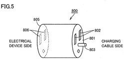
- Fig. 5 is a schematic diagram showing an example of adapter 800 used during power feeding to outside, as described with reference to Fig. 4 .
- adapter 800 includes a connection unit 801 for connecting plug 320 of charging cable 300 and a connection unit 805 for connecting power plug 710 of external electrical device 700.
- Connection unit 801 on the charging cable 300 side is provided with a terminal unit 802 to which the terminal of plug 320 is connected. Also, connection unit 801 is further provided with a terminal 803 for transmitting a signal showing connection between adapter 800 and plug 320. As shown in Fig. 6 , plug 320 is provided with a terminal unit 322 accommodating terminal 803. When plug 320 and adapter 800 are connected to each other, terminal 803 and terminal unit 322 are electrically coupled.
- connection unit 805 on the electrical device 700 side is provided with a terminal unit 806 corresponding to the terminal shape of power plug 710 of electrical device 700.
- Terminal unit 806 has a shape that is, for example, adapted to a voltage (100V, 200V and the like) to be used and the standards specified in the country in which this terminal unit is to be used.
- Fig. 5 shows an example in which connection units 801 and 805 are integrally structured and housed in the same housing, which may be however configured, for example as with an adapter 800# shown in Fig. 7 , such that a connector 810 on the charging cable 300 side and a connector 820 on the electrical device 700 side can be separated from each other, and coupled to each other through a cable 830 serving as a power transmission medium.
- Fig. 8 is a detailed diagram of a circuit in the case where adapter 800 according to the first embodiment is used for power feeding.
- the configuration of vehicle 10 is the same as that in Fig. 2 , and components in vehicle 10 and charging cable 300 are partially not shown in Fig. 8 .
- the same components as those in Fig. 2 will not be explained in Fig. 8 .
- adapter 800 includes a signal generation unit 850 in addition to connection units 801 and 805.
- signal generation unit 850 When plug 320 of charging cable 300 is connected to adapter 800, signal generation unit 850 is electrically connected to a signal line L4 of charging cable 300. When being connected to signal line L4, signal generation unit 850 supplies, to CCID control unit 610 of charging cable 300, a signal CNCT2 showing connection between charging cable 300 and adapter 800. While a specific example of signal generation unit 850 will be explained in and after Fig. 15 , signal generation unit 850 may be a control device having a CPU or may be a control circuit exhibiting a desired function. When signal generation unit 850 requires a power supply voltage for driving, the power supply voltage is supplied from the battery (not shown) incorporated in adapter 800.
- CCID control unit 610 determines whether or not charging cable 300 and adapter 800 are connected to each other. When determining that charging cable 300 and adapter 800 are connected to each other, CCID control unit 610 outputs pilot signal CPLT to vehicle ECU 170 using a frequency and/or a potential different from those during external charging. Consequently, CCID control unit 610 can cause vehicle ECU 170 to perform a power feeding operation.
- Fig. 9 is a time chart for illustrating the power feeding control in the first embodiment.
- the horizontal axis shows time while the vertical axis shows the state of connection of adapter 800, the potential of pilot signal CPLT, the potential of connection signal CNCT, the state of connection signal CNCT2, the states of switches SW1 and SW2, the state of CCID relay 332, and the execution state of the power feeding process.
- charging cable 300 is not connected to inlet 270 until time t20.
- switches SW1, SW2 and CCID relay 332 are in the OFF state while the potential of pilot signal CPLT is 0V.
- the potential of connection signal CNCT is V11 (> 0V) while connection signal CNCT2 is in the OFF state.
- pilot signal CPLT is V1 (for example, 12V) and pilot signal CPLT is in a non-oscillation state.
- connection signal CNCT is decreased by connection detecting circuit 312.
- CPU 508 detects that the potential of connection signal CNCT has been decreased, thereby detecting that charging cable 300 has been connected to inlet 270.
- CPU 508 activates control signal S1 to thereby turn on switch SW1 (time t21).
- the potential of pilot signal CPLT is decreased to V2 (for example, 9V) by pull-down resistance R1 of resistance circuit 502.
- CCID control unit 610 recognizes that plug 320 of charging cable 300 has been connected to adapter 800.
- CCID control unit 610 closes CCID relay 332.
- CPU 508 detects that pilot signal CPLT has been oscillated. However, as described above, since an oscillation frequency Fsup of pilot signal CPLT output from CCID 330 during the power feeding operation is lower than an oscillation frequency Fchr during the charging operation, CPU 508 recognizes based on this difference between the oscillation frequencies that adapter 800 has been connected to charging cable 300 and that the power feeding operation has been instructed.
- CPU 508 closes the contact of relay 155 while controlling power conversion device 160 ( Fig. 1 ), thereby starting to supply electric power from power storage device 150 ( Fig. 1 ) to electrical device 700 (time t23).
- CCID control unit 610 stops the oscillation of pilot signal CPLT (time t25). In response to this, CPU 508 stops the power feeding process and also turns switch SW1 to be OFF (time t26). Then, CCID relay 332 is interrupted by CCID control unit 610 at time t27.
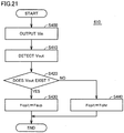
- Fig. 10 is a flowchart for illustrating a control process for selecting a frequency of pilot signal CPLT that is performed in CCID control unit 610 in the first embodiment.
- the process is implemented by executing the program stored in CCID control unit 610 in advance in predetermined cycles.
- the process can be implemented by constructing dedicated hardware (an electronic circuit).
- CCID control unit 610 obtains connection signal CNCT2 in step (which will be hereinafter abbreviated to S) 300. Then, CCID control unit 610 determines in S310 whether or not connection signal CNCT2 is ON, that is, whether or not charging cable 300 and adapter 800 are connected to each other. As described later, in the case where the potential of connection signal CNCT2 is changed due to connection between charging cable 300 and adapter 800, CCID control unit 610 determines in this S310 that connection signal CNCT2 has been turned ON, based on the fact that the potential of connection signal CNCT2 has been changed to a prescribed level.
- CCID control unit 610 When connection signal CNCT2 is OFF (NO in S310), CCID control unit 610 recognizes that adapter 800 is not connected to charging cable 300 and the normal external charging mode is employed. Then, in S330, CCID control unit 610 sets an oscillation frequency Fcplt of pilot signal CPLT at frequency Fchr for performing external charging, and oscillates pilot signal CPLT.
- CCID control unit 610 recognizes that adapter 800 is connected to charging cable 300 and the mode for power feeding to outside is employed. Then, in S320, CCID control unit 610 sets oscillation frequency Fcplt of pilot signal CPLT at frequency Fsup lower than frequency Fchr during external charging (Fsup ⁇ Fchr), and oscillates pilot signal CPLT.
- Fig. 11 is a flowchart for illustrating a control process for switching between a charging process and a power feeding process that is performed in vehicle ECU 170 in the first embodiment.
- the process is implemented by executing the program stored in CPU 508 of vehicle ECU 170 in advance in predetermined cycles.
- the process can be implemented by constructing dedicated hardware (an electronic circuit).
- CPU 508 determines in S100 whether or not pilot signal CPLT is oscillating.
- pilot signal CPLT is oscillating (YES in S100)
- CPU 508 recognizes that charging cable 300 is connected to inlet 270, and in S110, obtains oscillation frequency Fcplt of pilot signal CPLT.
- CPU 508 determines in S120 whether or not the obtained oscillation frequency Fcplt is equal to oscillation frequency Fchr in the case of the charging operation.
- the obtained oscillation frequency Fcplt does not need to be completely equal to oscillation frequency Fchr during the charging operation, and the difference between oscillation frequency Fcplt and oscillation frequency Fchr only needs to fall within a prescribed range (IFcplt - Fchrl ⁇ ⁇ 1).
- oscillation frequency Fcplt is not equal to oscillation frequency Fchr (NO in S120)
- the process proceeds to S140, in which CPU 508 determines whether or not the obtained oscillation frequency Fcplt is equal to oscillation frequency Fsup during the power feeding operation. Also in this case, similarly to the case of determination in S120, the obtained oscillation frequency Fcplt does not need to be completely equal to oscillation frequency Fsup during the power feeding operation, and the difference between oscillation frequency Fcplt and oscillation frequency Fsup only needs to fall within a prescribed range (IFcplt - Fsupl ⁇ ⁇ 2).
- the electric power from the vehicle can be supplied to the electrical device external to the vehicle through the charging cable by using a conversion adaptor for a charging cable.
- oscillation frequency Fsup of pilot signal CPLT at the time when adapter 800 is connected to charging cable 300 is lower than oscillation frequency Fchr at the time when adapter 800 is not connected to charging cable 300 (that is, the oscillation cycle is relatively long).
- oscillation frequency Fsup may be set to be greater than oscillation frequency Fchr.
- Fig. 12 is a time chart for illustrating the control during power feeding in the modification of the first embodiment.
- the horizontal axis shows time while the vertical axis shows the state of connection of adapter 800, the potential of pilot signal CPLT, the potential of connection signal CNCT, the state of connection signal CNCT2, the states of switches SW1 and SW2, the state of CCID relay 332, and the execution state of the power feeding process.
- pilot signal CPLT when charging cable 300 is connected to inlet 270, CCID 330 generates pilot signal CPLT. It is to be noted that, at this time t30, the potential of pilot signal CPLT is V1 (for example, 12V) while pilot signal CPLT is in a non-oscillation state.
- CPU 508 detects that the potential of connection signal CNCT has been decreased, thereby detecting that charging cable 300 has been connected to inlet 270.
- CPU 508 activates control signal S1 to turn switch SW1 to be ON (time t31).
- the potential of pilot signal CPLT is decreased to V2 (for example, 9V) by pull-down resistance R1 of resistance circuit 502.
- CCID control unit 610 recognizes that plug 320 of charging cable 300 has been connected to adapter 800.
- CCID control unit 610 outputs the potential of pilot signal CPLT as a potential V4 (for example, 15V) greater than a potential V1 in the case where charging cable 300 is connected.
- CPU 508 of vehicle ECU 170 detects that the potential of pilot signal CPLT is V4, thereby recognizing that adapter 800 has been connected to charging cable 300.
- control signal S1 of switch SW1 may be kept activated or deactivated.
- CCID control unit 610 oscillates pilot signal CPLT. Since it can already be recognized based on the potential of pilot signal CPLT that adapter 800 is connected, the oscillation frequency at this time may be equal to oscillation cycle Tchr as in the case of external charging, or may be different therefrom. Then, CCID control unit 610 closes CCID relay 332.
- CPU 508 When CPU 508 detects oscillation of pilot signal CPLT, it controls relay 155 and power conversion device 160, thereby performing the operation for feeding electric power to electrical device 700 (time t33 in Fig. 12 ).
- CCID control unit 610 stops the oscillation of pilot signal CPLT.
- CPU 508 ends the power feeding process (time t35 in Fig. 12 ) while CCID control unit 610 opens CCID relay 332 (time t36 in Fig. 12 ).
- Fig. 13 is a flowchart for illustrating a control process for selecting a voltage of pilot signal CPLT that is performed in CCID control unit 610 in the modification of the first embodiment.
- Fig. 13 shows the same flowchart as that described in Fig. 10 in the first embodiment except that steps S320 and S330 are replaced with S320A and S330A, respectively. The same steps as those in Fig. 10 will not be repeated in Fig. 13 .
- connection signal CNCT2 is OFF, that is, adapter 800 is not connected to charging cable 300 (NO in S310)
- CCID control unit 610 sets, in S330A, a potential Vcplt of pilot signal CPLT at potential V1 for performing external charging, to oscillate pilot signal CPLT.
- connection signal CNCT2 is ON, that is, adapter 800 is connected to charging cable 300 (NO in S310)
- CCID control unit 610 sets, in S320A, potential Vcplt of pilot signal CPLT at potential V4 for performing power feeding to outside, to oscillate pilot signal CPLT.
- Fig. 14 is a flowchart for illustrating a control process for switching between the charging process and the power feeding process that is performed in vehicle ECU 170 in the modification of the first embodiment.
- CPU 508 determines in S200 whether or not the potential of connection signal CNCT is decreased.
- connection signal CNCT When the potential of connection signal CNCT is not decreased (NO in S200), charging cable 300 is not connected to inlet 270, and therefore, CPU 508 ends the process.
- connection signal CNCT When the potential of connection signal CNCT is decreased (YES in S200), the process proceeds to S210, in which CPU 508 obtains potential Vcplt of pilot signal CPLT.
- CPU 508 determines in S220 whether or not the obtained potential Vcplt is not more than potential V1 at the time of the charging operation (Vcplt ⁇ V1).
- the electric power from the vehicle can be supplied to the electrical device external to the vehicle through the charging cable by using a conversion adaptor for a charging cable.
- the signal generation unit included in the adapter is a control circuit serving to output an ON signal when the adapter and the charging cable are connected to each other, and output an OFF signal when the adapter and the charging cable are not connected to each other.
- variations of a specific example of the signal generation unit included in the adapter will be hereinafter described with reference to Figs. 15 to 22 .
- Fig. 15 is a diagram for illustrating an adapter 800A including a signal generation unit 850A having a resistance R30.
- an electric power is provided from a power supply node 616 to signal line L4 in charging cable 300 through a pull-up resistance R21.
- the potential of signal line L4 becomes a potential set by power supply node 616.
- signal line L4 When adapter 800A is connected to charging cable 300, signal line L4 is connected to a ground through resistance R30 included in signal generation unit 850A. This causes the potential of signal line L4 to be decreased to a potential that is obtained by dividing the potential on power supply node 616 by resistances R21 and R30.
- CCID control unit 610 detects such a change in the potential of signal line L4, thereby detecting that adapter 800A has been connected to charging cable 300.
- Fig. 16 is a diagram for illustrating an adapter 800B including a signal generation unit 850B having a switch SW10.
- an electric power is provided from power supply node 616 to signal line L4 in charging cable 300 through pull-up resistance R21, as in Fig. 15 .
- the potential of signal line L4 becomes a potential set by power supply node 616.
- signal line L4 is connected to a ground via switch SW10 included in signal generation unit 850B. This causes the potential of signal line L4 to be decreased to a ground potential.
- CCID control unit 610 detects such a change in the potential of signal line L4, thereby detecting that adapter 800B has been connected to charging cable 300.
- Fig. 17 is a diagram for illustrating an adapter 800C having an operation member 860 for operating switch 321 serving as a switching unit included in charging cable 300, as a signal generation unit.
- signal line L4 is connected to a ground within charging cable 300 via switch 321 included in plug 320. Furthermore, as in Fig. 15 , an electric power is provided from power supply node 616 to signal line L4 in charging cable 300 through pull-up resistance R21.
- switch 321 the contact is closed, for example, in the state where adapter 800C is not connected to charging cable 300. Therefore, when adapter 800C has not been connected, the potential of signal line L4 becomes a ground potential.
- Operation member 860 is, for example, a rod-shaped member and provided in place of terminal 803 shown in adapter 800 in Fig. 5 .
- operation member 860 directly or indirectly opens the contact of switch 321 within plug 320. This causes signal line L4 to be disconnected from a ground. Then, the potential of signal line L4 is increased from a ground potential to the potential set by power supply node 616.
- CCID control unit 610 detects such a change in the potential of signal line L4, thereby detecting that adapter 800C has been connected to charging cable 300.
- Fig. 17 shows the configuration in which switch 321 is closed when adapter 800C is not connected to charging cable 300 and opened when adapter 800C is connected to charging cable 300.
- switch 321 may be configured to be opened when adapter 800C is not connected to charging cable 300 and closed when adapter 800C is connected to charging cable 300.
- Fig. 18 is a diagram for illustrating an adapter 800D provided with a bypass circuit 870 as a signal generation unit.
- bypass circuit 870 is electrically connected between a ground and one of power lines 341 extending from vehicle 10 to electrical device 700. Furthermore, when adapter 800D is connected to charging cable 300, bypass circuit 870 is also connected to signal line L4 of charging cable 300.
- Bypass circuit 870 has a configuration, for example, like a circuit 871 shown in Fig. 19 or a circuit 872 shown in Fig. 20 .
- Circuit 871 shown in Fig. 19 includes resistances R50 and R51 that are connected in series between terminals 50 and 51 electrically connected to one of power lines 341 and signal line L4, respectively.
- the connection node of resistances R50 and R51 is connected to a ground.
- circuit 872 shown in Fig. 20 includes a coil L50, a capacitor C50 and a resistance R55 that are connected in series between terminal 50 and a ground.
- the connection node of capacitor C50 and resistance R55 is connected to terminal 51.
- CCID control unit 610 applies a high frequency signal Vin to the power line to which bypass circuit 870 is connected.
- a high frequency signal Vin is superimposed on its power supply voltage.
- Bypass circuit 870 generates a signal Vout corresponding to high frequency signal Vin by a circuit as shown in Figs. 19 and 20 . Then, this generated signal Vout is transmitted through signal line L4 to CCID control unit 610.
- CCID control unit 610 detects signal Vout generated by bypass circuit 870, thereby detecting that adapter 800D has been connected to charging cable 300.
- Fig. 21 is a flowchart for illustrating a control process for selecting a frequency of pilot signal CPLT that is performed in CCID control unit 610 in the case where bypass circuit 870 shown in Fig. 18 is used.
- CCID control unit 610 applies high frequency signal Vin to one of the power lines continuously or for each prescribed time period. Then, in S410, while being applying high frequency signal Vin, CCID control unit 610 detects whether or not output signal Vout from bypass circuit 870 exists in signal line L4.
- CCID control unit 610 When output signal Vout is not detected (NO in S410), CCID control unit 610 recognizes that adapter 800D is not connected to charging cable 300. Then, the process proceeds to S440, in which CCID control unit 610 sets oscillation frequency Fcplt of pilot signal CPLT at frequency Fchr for performing external charging, to oscillate pilot signal CPLT.
- CCID control unit 610 recognizes that adapter 800D has been connected to charging cable 300. Then, the process proceeds to S430, in which CCID control unit 610 sets oscillation frequency Fcplt of pilot signal CPLT at frequency Fsup lower than frequency Fchr (Fsup ⁇ Fchr) in the case of external charging, to oscillate pilot signal CPLT.
- Fig. 22 is a diagram for illustrating an adapter 800E provided with a filter circuit 870A as a signal generation unit.
- filter circuit 870A is electrically connected between power lines 341 that each connect vehicle 10 and electrical device 700.
- Filter circuit 870A is, for example, a high-pass filter or a bandpass filter through which the signal passes that has a specific frequency higher than the power supply frequency transmitted via power line 341. Accordingly, filter circuit 870A allows the high frequency signal applied to one of the power lines to pass through the other of the power lines.
- CCID control unit 610 applies a high frequency signal to one of the power lines.
- the applied high frequency signal is caused to pass through filter circuit 870A and appears on the other of power lines 341. Therefore, while being applying a high frequency signal to one of the power lines, CCID control unit 610 detects this high frequency signal in the other of the power lines, thereby detecting that adapter 800E is connected to charging cable 300.
- Fig. 23 is a detailed diagram of a circuit in the case where electric power is supplied through a charging cable 300A by using an adapter 800F in the second embodiment.
- charging cable 300A does not have CCID 330 as in charging cable 300 described in the first embodiment. Accordingly, pilot signal CPLT is not input to CPU 508 of vehicle ECU 170.
- vehicle ECU 170 When performing external charging in such a configuration, vehicle ECU 170 generally determines whether or not the charging operation is performed based on connection signal CNCT and also on existence or non-existence of the power supply voltage supplied between power lines ACL1 and ACL2 from the external power supply.
- a signal generation unit 850C included in adapter 800F is directly connected to CPU 508 of vehicle ECU 170 through a signal line L5 within charging cable 300A, and supplies connection signal CNCT2 to CPU 508. Based on connection signal CNCT2, CPU 508 detects that adapter 800F is connected to charging cable 300A, and switches between the charging operation and the power feeding operation.
- Fig. 24 is a flowchart for illustrating a control process for switching between the charging process and the power feeding process that is performed in vehicle ECU 170 in the second embodiment.
- CPU 508 of vehicle ECU 170 obtains connection signal CNCT2 from adapter 800F.
- CPU 508 determines whether or not connection signal CNCT2 is ON.
- connection signal CNCT2 is OFF (NO in S510)
- the process proceeds to S530, in which CPU 508 performs the charging process.
- connection signal CNCT2 is ON (YES in S510)
- the process proceeds to S520, in which CPU 508 performs the power feeding process.
- signal generation unit 850C may have a control circuit capable of outputting a signal corresponding to pilot signal CPLT of CCID 330 in charging cable 300.
- signal line L5 of charging cable 300A is connected to control pilot line L1 via inlet 270.
- signal generation unit 850C outputs, to vehicle ECU 170 through charging cable 300A, the signal having frequency Fsup different from frequency Fchr of the pilot signal used during external charging.
- CPU 508 detects that adapter 800F is connected to charging cable 300A, and switches between the charging operation and the power feeding operation.
- the vehicle ECU directly detects the signal from the signal generation unit provided in the adapter, thereby allowing the electric power from the vehicle to be supplied to external electrical devices through the charging cable.
Claims (14)
- Système comprenant une source d'alimentation (150 ; 120 ; 140) comportant un dispositif de stockage d'énergie (150) monté dans un véhicule pouvant être chargé de l'extérieur (10), un dispositif électrique (700) externe audit véhicule (10), un adaptateur (800, 800#), un câble de charge (300), et une alimentation électrique externe, externe audit véhicule (10) ; ledit système étant conçu pour fournir de l'énergie électrique provenant de ladite source d'alimentation (150 ; 120, 140) comportant ledit dispositif de stockage d'énergie (150) monté dans ledit véhicule pouvant être chargé de l'extérieur (10), audit dispositif électrique (700) externe audit véhicule (10) par connexion dudit adaptateur (800, 800#) audit câble de charge (300),
ledit dispositif de stockage d'énergie (150) stockant l'énergie électrique fournie à partir de ladite alimentation électrique externe, externe audit véhicule (10) par le biais dudit câble de charge (300) au cours d'une charge externe pour charger ledit dispositif de stockage d'énergie (150), ledit câble de charge (300) étant connecté entre ledit véhicule (10) et ladite alimentation électrique externe au cours de la charge externe, ledit adaptateur comprenant :une première unité de connexion (801, 811) apte à connecter une prise électrique mâle (320) dudit câble de charge (300) à connecter à ladite alimentation électrique externe au cours de la charge externe ;une seconde unité de connexion (805, 821) électriquement connectée à ladite première unité de connexion (801, 811) et apte à connecter une prise électrique mâle (710) dudit dispositif électrique (700) ; etune unité de production de signaux (850, 850A, 850B, 850C, 860, 870, 870A) conçue pour produire un signal d'instruction d'alimentation en énergie, par connexion entre ledit adaptateur (800, 800#) et ledit câble de charge (300), de manière que le véhicule (10), en réponse audit signal d'instruction d'alimentation en énergie lorsque ledit adaptateur (800, 800#) est connecté entre ladite prise électrique mâle (320) dudit câble de charge (300) et ladite prise électrique mâle (710) dudit dispositif électrique (700), fournisse l'énergie électrique provenant de ladite source d'alimentation (150 ; 120, 140) audit dispositif électrique (700) par le biais dudit câble de charge (300) connecté audit véhicule (10). - Système selon la revendication 1, dans lequel :ledit véhicule (10) comporte un dispositif de conversion de puissance (160) destiné à convertir l'énergie électrique provenant de ladite source d'alimentation (150 ; 120, 140) pour fournir l'énergie électrique convertie audit câble de charge (300), et un premier dispositif de commande (170) destiné à commander ledit dispositif de conversion de puissance (160),ledit câble de charge (300) comporte un second dispositif de commande (300) apte à émettre et à recevoir un signal vers et depuis ledit premier dispositif de commande (170),par connexion entre ledit adaptateur (800, 800#) et ledit câble de charge (300), ladite unité de production de signaux (850, 850A, 850B, 860, 870, 870A) est conçue pour fournir, audit second dispositif de commande (330), un signal indiquant la connexion entre ledit adaptateur (800, 800#) et ledit câble de charge (300) pour faire que ledit second dispositif de commande (330) délivre ledit signal d'instruction d'alimentation en énergie audit premier dispositif de commande (170), eten réponse audit signal d'instruction d'alimentation en énergie, ledit premier dispositif de commande (170) est conçu pour attaquer ledit dispositif de conversion de puissance (160) pour fournir l'énergie électrique provenant de ladite source d'alimentation (150 ; 120, 140) audit dispositif électrique (700).
- Système selon la revendication 2, dans lequel ladite unité de production de signaux (850A, 850B, 860) est conçue pour modifier un potentiel de trajet de signal (L4) connecté audit second dispositif de commande (330) afin de fournir le signal indiquant la connexion entre ledit adaptateur (800, 800#) et ledit câble de charge (300) audit second dispositif de commande (330).
- Système selon la revendication 3, dans lequel ladite unité de production de signaux (850A) comporte une résistance (R30) et est conçue pour connecter ledit trajet de signal (L4) à une terre par le biais de ladite résistance (R30) par connexion entre ledit adaptateur (800, 800#) et ledit câble de charge (300).
- Système selon la revendication 3, dans lequel ladite unité de production de signaux (850B) comporte un interrupteur (SW10) et est conçue pour connecter électriquement ledit trajet de signal (L4) à une terre, par le biais dudit interrupteur (SW10) par connexion entre ledit adaptateur (800, 800#) et ledit câble de charge (300).
- Système selon la revendication 3, dans lequel :ledit câble de charge (300) comporte une unité de commutation (321) conçue pour commuter entre la conduction et la non-conduction entre ledit trajet de signal (L4) et une terre, etladite unité de production de signaux comporte un organe d'actionnement (860) conçu pour permettre à un état conducteur de ladite unité de commutation (321) d'être changé par connexion entre ledit adaptateur (800, 800#) et ledit câble de charge (300).
- Système selon la revendication 6, dans lequel :ladite unité de commutation est un interrupteur (321),ledit interrupteur (321) est dans un état conducteur, dans un état où ledit adaptateur (800, 800#) et ledit câble de charge (300) ne sont pas connectés, etledit organe d'actionnement (860) est conçu pour amener ledit interrupteur (321) dans un état non conducteur par connexion dudit adaptateur (800, 800#) audit câble de charge (300).
- Système selon la revendication 2, dans lequel ladite unité de production de signaux (870, 870A) est conçue pour délivrer, audit second dispositif de commande (330) un signal répondant à la réception d'un signal émis en provenance dudit second dispositif de commande (330) à l'aide d'une paire de trajets de transmission de puissance dans ledit câble de charge (300) en tant que signal indiquant la connexion entre ledit adaptateur (800, 800#) et ledit câble de charge (300), pour faire que ledit second dispositif de commande (330) délivre ledit signal d'instruction d'alimentation en énergie audit premier dispositif de commande (170).
- Système selon la revendication 8, dans lequel ladite unité de production de signaux comporte un circuit de dérivation (870) conçu pour faire dériver une partie d'un signal à haute fréquence émis en provenance dudit second dispositif de commande (330) vers un trajet de ladite paire de trajets de transmission de puissance, et délivrer le signal ayant dérivé audit second dispositif de commande (330).
- Système selon la revendication 8, dans lequel ladite unité de production de signaux comporte un circuit de filtrage (870A) conçu pour faire qu'un signal à haute fréquence émis en provenance dudit second dispositif de commande (330) vers un trajet de ladite paire de trajets de transmission de puissance, passe par l'autre des trajets de transmission de puissance.
- Système selon la revendication 2, dans lequel ledit signal d'instruction d'alimentation en énergie est délivré en provenance dudit second dispositif de commande (330) audit premier dispositif de commande (170), à l'aide d'un signal pilote utilisé pour transmettre des informations au sujet d'une capacité de courant dudit câble de charge (300) lors de la réalisation d'une charge externe.
- Système selon la revendication 11, dans lequel ledit signal d'instruction d'alimentation en énergie est délivré à l'aide d'une fréquence différente d'une fréquence dudit signal pilote utilisé au cours d'une charge externe.
- Système selon la revendication 11, dans lequel ledit signal d'instruction d'alimentation en énergie est délivré à l'aide d'un potentiel différent d'un potentiel dudit signal pilote utilisé au cours d'une charge externe.
- Procédé pour alimenter en énergie électrique provenant d'une source d'alimentation (150 ; 120, 140) comportant un dispositif de stockage d'énergie (150) monté dans un véhicule pouvant être chargé de l'extérieur (10), un dispositif électrique (700) externe audit véhicule (10) par connexion d'un adaptateur (800, 800#) à un câble de charge (300), ledit dispositif de stockage d'énergie (150) stockant l'énergie électrique fournie à partir d'une alimentation électrique externe, externe audit véhicule (10) par le biais dudit câble de charge (300) au cours d'une charge externe pour charger ledit dispositif de stockage d'énergie (150), ledit câble de charge (300) étant connecté entre ledit véhicule (10) et ladite alimentation électrique externe au cours de la charge externe, ledit véhicule (10) comportant :une entrée (270) pour connecter ledit câble de charge (300) au cours d'une charge externe, etun dispositif de conversion de puissance (160) destiné à convertir l'énergie électrique provenant de ladite source d'alimentation (150 ; 120, 140) pour fournir l'énergie électrique convertie à ladite entrée (270),ledit adaptateur (800, 800#) comportant :une première unité de connexion (801, 811) apte à connecter une prise électrique mâle (320) dudit câble de charge (300) à connecter à ladite alimentation électrique externe au cours de la charge externe,une seconde unité de connexion (805, 821) électriquement connectée à ladite première unité de connexion (801, 811) et apte à connecter une prise électrique mâle (710) dudit dispositif électrique (700), etune unité de production de signaux (850, 850A, 850B, 850C, 860, 870, 870A) conçue pour produire un signal d'instruction d'alimentation en énergie, par connexion entre ledit adaptateur (800, 800#) et ledit câble de charge (300),ledit procédé comprenant les étapes consistant à :connecter ledit câble de charge (300) à ladite entrée (270) ;connecter ladite prise électrique mâle (320) dudit câble de charge (300) à ladite première unité de connexion (801, 811) dudit adaptateur (800, 800#) ;connecter la prise électrique mâle (710) dudit dispositif électrique (700) à ladite seconde unité de connexion (805, 821) dudit adaptateur (800, 800#) ;recevoir en provenance dudit adaptateur un signal d'instruction d'alimentation en énergie qui est produit par connexion entre ledit adaptateur (800, 800#) et ledit câble de charge (300) ; etcommander ledit dispositif de conversion de puissance (160), en réponse audit signal d'instruction d'alimentation en énergie, lorsque ledit adaptateur (800, 800#) est connecté entre ladite prise électrique mâle (320) dudit câble de charge (300) et ladite prise électrique mâle (710) dudit dispositif électrique (700), pour fournir l'énergie électrique provenant de ladite source d'alimentation (150 ; 120, 140) audit dispositif électrique (700) par le biais dudit câble de charge (300) connecté audit véhicule (10).
Applications Claiming Priority (1)
| Application Number | Priority Date | Filing Date | Title |
|---|---|---|---|
| PCT/JP2011/056947 WO2012127649A1 (fr) | 2011-03-23 | 2011-03-23 | Adaptateur, et véhicule ainsi que procédé permettant de fournir de l'énergie à l'aide de celui-ci |
Publications (3)
| Publication Number | Publication Date |
|---|---|
| EP2690741A1 EP2690741A1 (fr) | 2014-01-29 |
| EP2690741A4 EP2690741A4 (fr) | 2015-02-25 |
| EP2690741B1 true EP2690741B1 (fr) | 2018-10-17 |
Family
ID=46878842
Family Applications (1)
| Application Number | Title | Priority Date | Filing Date |
|---|---|---|---|
| EP11861454.4A Not-in-force EP2690741B1 (fr) | 2011-03-23 | 2011-03-23 | Adaptateur, et véhicule ainsi que procédé permettant de fournir de l'énergie à l'aide de celui-ci |
Country Status (5)
| Country | Link |
|---|---|
| US (1) | US9614379B2 (fr) |
| EP (1) | EP2690741B1 (fr) |
| JP (1) | JP5708790B2 (fr) |
| CN (1) | CN103444042B (fr) |
| WO (1) | WO2012127649A1 (fr) |
Families Citing this family (25)
| Publication number | Priority date | Publication date | Assignee | Title |
|---|---|---|---|---|
| EP2677607B1 (fr) * | 2011-02-15 | 2019-06-19 | Toyota Jidosha Kabushiki Kaisha | Adaptateur et véhicule pourvu dudit adaptateur, et procédé de commande de véhicule |
| US9090169B2 (en) * | 2011-03-23 | 2015-07-28 | Toyota Jidosha Kabushiki Kaisha | Adapter and vehicle for performing power feeding using adapter |
| JP5852404B2 (ja) * | 2011-10-21 | 2016-02-03 | 株式会社ケーヒン | 電子制御装置 |
| JP5960966B2 (ja) | 2011-10-21 | 2016-08-02 | 株式会社ケーヒン | 電子制御装置 |
| US9150108B2 (en) * | 2012-04-16 | 2015-10-06 | Ford Global Technologies, Llc | High-frequency signal injection based high voltage interlock |
| JP5811287B2 (ja) * | 2012-11-05 | 2015-11-11 | トヨタ自動車株式会社 | 車両 |
| EP2940827B1 (fr) * | 2012-12-26 | 2020-05-06 | Mitsubishi Jidosha Kogyo Kabushiki Kaisha | Dispositif d'alimentation électrique utilisant un véhicule électrique |
| US9841451B2 (en) | 2013-03-15 | 2017-12-12 | Schneider Electric USA, Inc. | Zone fault detection method and system for electric vehicle charging systems |
| JP6156484B2 (ja) * | 2013-03-21 | 2017-07-05 | トヨタ自動車株式会社 | 車両 |
| JP6003767B2 (ja) * | 2013-03-28 | 2016-10-05 | トヨタ自動車株式会社 | 電力伝達用ケーブル |
| JP2014204484A (ja) | 2013-04-01 | 2014-10-27 | パナソニック株式会社 | 系統保護装置、電路切替装置、および電力供給システム |
| JP2014207766A (ja) * | 2013-04-12 | 2014-10-30 | パナソニック株式会社 | 過電流検出装置、及び当該過電流検出装置を用いた充放電システム、分電盤、充電制御装置、車両用充放電装置、車両用電気機器 |
| JP6748954B2 (ja) * | 2013-04-24 | 2020-09-02 | パナソニックIpマネジメント株式会社 | 電力変換システム、コネクタ |
| JP5735050B2 (ja) * | 2013-06-28 | 2015-06-17 | トヨタ自動車株式会社 | 車両および受電装置 |
| KR101728197B1 (ko) * | 2013-07-22 | 2017-04-18 | 엘에스산전 주식회사 | 휴대용 충전기 |
| CN103701166B (zh) * | 2013-12-13 | 2016-06-01 | 郑州宇通客车股份有限公司 | 一种电动汽车及其交流充电车辆控制装置供电电路 |
| JP6146435B2 (ja) * | 2015-04-23 | 2017-06-14 | トヨタ自動車株式会社 | 車両 |
| US10520529B2 (en) * | 2016-03-23 | 2019-12-31 | Cooper Technologies Company | Adapters for testing electrical equipment |
| CN108128176B (zh) * | 2016-12-01 | 2020-02-07 | 比亚迪股份有限公司 | 一种电动汽车的充放电控制电路及电动车充放电连接装置 |
| JP6992462B2 (ja) * | 2017-12-08 | 2022-01-13 | トヨタ自動車株式会社 | 外部給電システム及びその漏電検知方法 |
| FR3090228B1 (fr) * | 2018-12-13 | 2021-05-07 | Renault Sas | Dispositif d’alimentation en courant électrique utilisant une batterie d’accumulateurs de véhicule automobile |
| FR3089893B1 (fr) * | 2018-12-14 | 2024-03-08 | Renault Sas | Système de commande d’alimentation autonome de charges pour un véhicule automobile |
| US11283228B2 (en) * | 2019-11-12 | 2022-03-22 | Toyota Motor Engineering And Manufacturing North America, Inc. | Universal adapter for sensors |
| JP2023026864A (ja) * | 2021-08-16 | 2023-03-01 | トヨタ自動車株式会社 | 車両制御装置、車両、電力供給システム、プログラム、放電コネクタ、電力設備および電力供給方法 |
| JP2023026862A (ja) * | 2021-08-16 | 2023-03-01 | トヨタ自動車株式会社 | 車両制御装置、車両、電力供給システム、プログラム、放電コネクタおよび電力供給方法 |
Citations (1)
| Publication number | Priority date | Publication date | Assignee | Title |
|---|---|---|---|---|
| EP2200150A1 (fr) * | 2007-10-23 | 2010-06-23 | Toyota Jidosha Kabushiki Kaisha | Véhicule électrique |
Family Cites Families (12)
| Publication number | Priority date | Publication date | Assignee | Title |
|---|---|---|---|---|
| US20040155625A1 (en) * | 1995-02-17 | 2004-08-12 | Floyd Herbert R. | Two cordless activating chargers actuating one another about vehicles and performing the activation of other devices also |
| JPH09261887A (ja) | 1996-03-18 | 1997-10-03 | Yazaki Corp | 車両用電源分配装置における発電制御装置 |
| FR2832262A1 (fr) | 2001-11-09 | 2003-05-16 | France Telecom | Procede et dispositif d'alimentation en energie electrique d'un appareil |
| JP4736862B2 (ja) * | 2006-03-03 | 2011-07-27 | トヨタ自動車株式会社 | 車両、電力授受方法および電気装置 |
| CN103078368B (zh) * | 2006-03-15 | 2016-04-13 | 株式会社半导体能源研究所 | 电力供应系统和用于机动车的电力供应系统 |
| US7642671B2 (en) * | 2006-04-28 | 2010-01-05 | Acco Brands Usa Llc | Power supply system providing two output voltages |
| JP4332861B2 (ja) * | 2008-01-16 | 2009-09-16 | トヨタ自動車株式会社 | 車両の充電制御装置 |
| JP4380776B1 (ja) | 2008-07-25 | 2009-12-09 | トヨタ自動車株式会社 | 充放電システムおよび電動車両 |
| WO2010097922A1 (fr) * | 2009-02-26 | 2010-09-02 | トヨタ自動車株式会社 | Adaptateur convertisseur de fiche |
| JP5412999B2 (ja) * | 2009-07-02 | 2014-02-12 | トヨタ自動車株式会社 | 電動車両 |
| JP5834229B2 (ja) * | 2009-12-22 | 2015-12-16 | パナソニックIpマネジメント株式会社 | 給電制御装置 |
| US20130154553A1 (en) * | 2011-02-22 | 2013-06-20 | Daniel W. Steele | Wireless Automated Vehicle Energizing System |
-
2011
- 2011-03-23 US US14/005,353 patent/US9614379B2/en active Active
- 2011-03-23 EP EP11861454.4A patent/EP2690741B1/fr not_active Not-in-force
- 2011-03-23 WO PCT/JP2011/056947 patent/WO2012127649A1/fr active Application Filing
- 2011-03-23 CN CN201180069516.6A patent/CN103444042B/zh not_active Expired - Fee Related
- 2011-03-23 JP JP2013505719A patent/JP5708790B2/ja active Active
Patent Citations (1)
| Publication number | Priority date | Publication date | Assignee | Title |
|---|---|---|---|---|
| EP2200150A1 (fr) * | 2007-10-23 | 2010-06-23 | Toyota Jidosha Kabushiki Kaisha | Véhicule électrique |
Also Published As
| Publication number | Publication date |
|---|---|
| CN103444042B (zh) | 2016-08-17 |
| EP2690741A1 (fr) | 2014-01-29 |
| US9614379B2 (en) | 2017-04-04 |
| WO2012127649A1 (fr) | 2012-09-27 |
| EP2690741A4 (fr) | 2015-02-25 |
| US20140002011A1 (en) | 2014-01-02 |
| JP5708790B2 (ja) | 2015-04-30 |
| JPWO2012127649A1 (ja) | 2014-07-24 |
| CN103444042A (zh) | 2013-12-11 |
Similar Documents
| Publication | Publication Date | Title |
|---|---|---|
| EP2690741B1 (fr) | Adaptateur, et véhicule ainsi que procédé permettant de fournir de l'énergie à l'aide de celui-ci | |
| US9090169B2 (en) | Adapter and vehicle for performing power feeding using adapter | |
| EP2677607B1 (fr) | Adaptateur et véhicule pourvu dudit adaptateur, et procédé de commande de véhicule | |
| US9434257B2 (en) | Power supply connector, vehicle and control method for vehicle | |
| US8179086B2 (en) | Control apparatus and control method | |
| US10000137B2 (en) | Hybrid vehicle with means for disconnection of a depleted auxiliary battery in order to allow for more rapid main battery charging | |
| US8768533B2 (en) | Vehicle, communication system, and communication device | |
| JP5343981B2 (ja) | 車両の充電システム | |
| US9216655B2 (en) | Vehicle and power supply system | |
| US8988042B2 (en) | Vehicle, charging system and control method for vehicle | |
| JP6044460B2 (ja) | 車両の電源装置 | |
| WO2014147781A1 (fr) | Véhicule | |
| US9960612B2 (en) | Charging and discharging system for a vehicle including a first fuse in the vehicle and a second fuse in a cable connected to the vehicle | |
| WO2015071712A1 (fr) | Système de charge et de décharge ayant un verrou de connecteur | |
| CN104584373A (zh) | 车辆电力控制系统和电力控制方法 | |
| JP2015057009A (ja) | 車両 | |
| WO2012164681A1 (fr) | Véhicule et procédé de commande de véhicule |
Legal Events
| Date | Code | Title | Description |
|---|---|---|---|
| PUAI | Public reference made under article 153(3) epc to a published international application that has entered the european phase |
Free format text: ORIGINAL CODE: 0009012 |
|
| 17P | Request for examination filed |
Effective date: 20131002 |
|
| AK | Designated contracting states |
Kind code of ref document: A1 Designated state(s): AL AT BE BG CH CY CZ DE DK EE ES FI FR GB GR HR HU IE IS IT LI LT LU LV MC MK MT NL NO PL PT RO RS SE SI SK SM TR |
|
| DAX | Request for extension of the european patent (deleted) | ||
| A4 | Supplementary search report drawn up and despatched |
Effective date: 20150126 |
|
| RIC1 | Information provided on ipc code assigned before grant |
Ipc: H02J 7/00 20060101AFI20150120BHEP Ipc: B60L 11/18 20060101ALI20150120BHEP |
|
| STAA | Information on the status of an ep patent application or granted ep patent |
Free format text: STATUS: EXAMINATION IS IN PROGRESS |
|
| 17Q | First examination report despatched |
Effective date: 20170517 |
|
| GRAP | Despatch of communication of intention to grant a patent |
Free format text: ORIGINAL CODE: EPIDOSNIGR1 |
|
| STAA | Information on the status of an ep patent application or granted ep patent |
Free format text: STATUS: GRANT OF PATENT IS INTENDED |
|
| INTG | Intention to grant announced |
Effective date: 20180508 |
|
| GRAS | Grant fee paid |
Free format text: ORIGINAL CODE: EPIDOSNIGR3 |
|
| GRAA | (expected) grant |
Free format text: ORIGINAL CODE: 0009210 |
|
| STAA | Information on the status of an ep patent application or granted ep patent |
Free format text: STATUS: THE PATENT HAS BEEN GRANTED |
|
| AK | Designated contracting states |
Kind code of ref document: B1 Designated state(s): AL AT BE BG CH CY CZ DE DK EE ES FI FR GB GR HR HU IE IS IT LI LT LU LV MC MK MT NL NO PL PT RO RS SE SI SK SM TR |
|
| REG | Reference to a national code |
Ref country code: GB Ref legal event code: FG4D |
|
| REG | Reference to a national code |
Ref country code: CH Ref legal event code: EP |
|
| REG | Reference to a national code |
Ref country code: IE Ref legal event code: FG4D |
|
| REG | Reference to a national code |
Ref country code: DE Ref legal event code: R096 Ref document number: 602011053093 Country of ref document: DE Ref country code: AT Ref legal event code: REF Ref document number: 1055119 Country of ref document: AT Kind code of ref document: T Effective date: 20181115 |
|
| REG | Reference to a national code |
Ref country code: DE Ref legal event code: R084 Ref document number: 602011053093 Country of ref document: DE |
|
| REG | Reference to a national code |
Ref country code: NL Ref legal event code: MP Effective date: 20181017 |
|
| REG | Reference to a national code |
Ref country code: LT Ref legal event code: MG4D |
|
| REG | Reference to a national code |
Ref country code: AT Ref legal event code: MK05 Ref document number: 1055119 Country of ref document: AT Kind code of ref document: T Effective date: 20181017 |
|
| PG25 | Lapsed in a contracting state [announced via postgrant information from national office to epo] |
Ref country code: NL Free format text: LAPSE BECAUSE OF FAILURE TO SUBMIT A TRANSLATION OF THE DESCRIPTION OR TO PAY THE FEE WITHIN THE PRESCRIBED TIME-LIMIT Effective date: 20181017 |
|
| PG25 | Lapsed in a contracting state [announced via postgrant information from national office to epo] |
Ref country code: BG Free format text: LAPSE BECAUSE OF FAILURE TO SUBMIT A TRANSLATION OF THE DESCRIPTION OR TO PAY THE FEE WITHIN THE PRESCRIBED TIME-LIMIT Effective date: 20190117 Ref country code: NO Free format text: LAPSE BECAUSE OF FAILURE TO SUBMIT A TRANSLATION OF THE DESCRIPTION OR TO PAY THE FEE WITHIN THE PRESCRIBED TIME-LIMIT Effective date: 20190117 Ref country code: PL Free format text: LAPSE BECAUSE OF FAILURE TO SUBMIT A TRANSLATION OF THE DESCRIPTION OR TO PAY THE FEE WITHIN THE PRESCRIBED TIME-LIMIT Effective date: 20181017 Ref country code: FI Free format text: LAPSE BECAUSE OF FAILURE TO SUBMIT A TRANSLATION OF THE DESCRIPTION OR TO PAY THE FEE WITHIN THE PRESCRIBED TIME-LIMIT Effective date: 20181017 Ref country code: LT Free format text: LAPSE BECAUSE OF FAILURE TO SUBMIT A TRANSLATION OF THE DESCRIPTION OR TO PAY THE FEE WITHIN THE PRESCRIBED TIME-LIMIT Effective date: 20181017 Ref country code: LV Free format text: LAPSE BECAUSE OF FAILURE TO SUBMIT A TRANSLATION OF THE DESCRIPTION OR TO PAY THE FEE WITHIN THE PRESCRIBED TIME-LIMIT Effective date: 20181017 Ref country code: HR Free format text: LAPSE BECAUSE OF FAILURE TO SUBMIT A TRANSLATION OF THE DESCRIPTION OR TO PAY THE FEE WITHIN THE PRESCRIBED TIME-LIMIT Effective date: 20181017 Ref country code: ES Free format text: LAPSE BECAUSE OF FAILURE TO SUBMIT A TRANSLATION OF THE DESCRIPTION OR TO PAY THE FEE WITHIN THE PRESCRIBED TIME-LIMIT Effective date: 20181017 Ref country code: AT Free format text: LAPSE BECAUSE OF FAILURE TO SUBMIT A TRANSLATION OF THE DESCRIPTION OR TO PAY THE FEE WITHIN THE PRESCRIBED TIME-LIMIT Effective date: 20181017 Ref country code: IS Free format text: LAPSE BECAUSE OF FAILURE TO SUBMIT A TRANSLATION OF THE DESCRIPTION OR TO PAY THE FEE WITHIN THE PRESCRIBED TIME-LIMIT Effective date: 20190217 |
|
| PG25 | Lapsed in a contracting state [announced via postgrant information from national office to epo] |
Ref country code: PT Free format text: LAPSE BECAUSE OF FAILURE TO SUBMIT A TRANSLATION OF THE DESCRIPTION OR TO PAY THE FEE WITHIN THE PRESCRIBED TIME-LIMIT Effective date: 20190217 Ref country code: GR Free format text: LAPSE BECAUSE OF FAILURE TO SUBMIT A TRANSLATION OF THE DESCRIPTION OR TO PAY THE FEE WITHIN THE PRESCRIBED TIME-LIMIT Effective date: 20190118 Ref country code: SE Free format text: LAPSE BECAUSE OF FAILURE TO SUBMIT A TRANSLATION OF THE DESCRIPTION OR TO PAY THE FEE WITHIN THE PRESCRIBED TIME-LIMIT Effective date: 20181017 Ref country code: RS Free format text: LAPSE BECAUSE OF FAILURE TO SUBMIT A TRANSLATION OF THE DESCRIPTION OR TO PAY THE FEE WITHIN THE PRESCRIBED TIME-LIMIT Effective date: 20181017 Ref country code: AL Free format text: LAPSE BECAUSE OF FAILURE TO SUBMIT A TRANSLATION OF THE DESCRIPTION OR TO PAY THE FEE WITHIN THE PRESCRIBED TIME-LIMIT Effective date: 20181017 |
|
| REG | Reference to a national code |
Ref country code: DE Ref legal event code: R097 Ref document number: 602011053093 Country of ref document: DE |
|
| PG25 | Lapsed in a contracting state [announced via postgrant information from national office to epo] |
Ref country code: DK Free format text: LAPSE BECAUSE OF FAILURE TO SUBMIT A TRANSLATION OF THE DESCRIPTION OR TO PAY THE FEE WITHIN THE PRESCRIBED TIME-LIMIT Effective date: 20181017 Ref country code: CZ Free format text: LAPSE BECAUSE OF FAILURE TO SUBMIT A TRANSLATION OF THE DESCRIPTION OR TO PAY THE FEE WITHIN THE PRESCRIBED TIME-LIMIT Effective date: 20181017 Ref country code: IT Free format text: LAPSE BECAUSE OF FAILURE TO SUBMIT A TRANSLATION OF THE DESCRIPTION OR TO PAY THE FEE WITHIN THE PRESCRIBED TIME-LIMIT Effective date: 20181017 |
|
| PLBE | No opposition filed within time limit |
Free format text: ORIGINAL CODE: 0009261 |
|
| STAA | Information on the status of an ep patent application or granted ep patent |
Free format text: STATUS: NO OPPOSITION FILED WITHIN TIME LIMIT |
|
| PG25 | Lapsed in a contracting state [announced via postgrant information from national office to epo] |
Ref country code: SK Free format text: LAPSE BECAUSE OF FAILURE TO SUBMIT A TRANSLATION OF THE DESCRIPTION OR TO PAY THE FEE WITHIN THE PRESCRIBED TIME-LIMIT Effective date: 20181017 Ref country code: SM Free format text: LAPSE BECAUSE OF FAILURE TO SUBMIT A TRANSLATION OF THE DESCRIPTION OR TO PAY THE FEE WITHIN THE PRESCRIBED TIME-LIMIT Effective date: 20181017 Ref country code: EE Free format text: LAPSE BECAUSE OF FAILURE TO SUBMIT A TRANSLATION OF THE DESCRIPTION OR TO PAY THE FEE WITHIN THE PRESCRIBED TIME-LIMIT Effective date: 20181017 Ref country code: RO Free format text: LAPSE BECAUSE OF FAILURE TO SUBMIT A TRANSLATION OF THE DESCRIPTION OR TO PAY THE FEE WITHIN THE PRESCRIBED TIME-LIMIT Effective date: 20181017 |
|
| 26N | No opposition filed |
Effective date: 20190718 |
|
| PG25 | Lapsed in a contracting state [announced via postgrant information from national office to epo] |
Ref country code: MC Free format text: LAPSE BECAUSE OF FAILURE TO SUBMIT A TRANSLATION OF THE DESCRIPTION OR TO PAY THE FEE WITHIN THE PRESCRIBED TIME-LIMIT Effective date: 20181017 Ref country code: SI Free format text: LAPSE BECAUSE OF FAILURE TO SUBMIT A TRANSLATION OF THE DESCRIPTION OR TO PAY THE FEE WITHIN THE PRESCRIBED TIME-LIMIT Effective date: 20181017 |
|
| REG | Reference to a national code |
Ref country code: CH Ref legal event code: PL |
|
| GBPC | Gb: european patent ceased through non-payment of renewal fee |
Effective date: 20190323 |
|
| PG25 | Lapsed in a contracting state [announced via postgrant information from national office to epo] |
Ref country code: LU Free format text: LAPSE BECAUSE OF NON-PAYMENT OF DUE FEES Effective date: 20190323 |
|
| REG | Reference to a national code |
Ref country code: BE Ref legal event code: MM Effective date: 20190331 |
|
| PG25 | Lapsed in a contracting state [announced via postgrant information from national office to epo] |
Ref country code: IE Free format text: LAPSE BECAUSE OF NON-PAYMENT OF DUE FEES Effective date: 20190323 Ref country code: CH Free format text: LAPSE BECAUSE OF NON-PAYMENT OF DUE FEES Effective date: 20190331 Ref country code: LI Free format text: LAPSE BECAUSE OF NON-PAYMENT OF DUE FEES Effective date: 20190331 Ref country code: GB Free format text: LAPSE BECAUSE OF NON-PAYMENT OF DUE FEES Effective date: 20190323 |
|
| PG25 | Lapsed in a contracting state [announced via postgrant information from national office to epo] |
Ref country code: FR Free format text: LAPSE BECAUSE OF NON-PAYMENT OF DUE FEES Effective date: 20190331 Ref country code: BE Free format text: LAPSE BECAUSE OF NON-PAYMENT OF DUE FEES Effective date: 20190331 |
|
| PG25 | Lapsed in a contracting state [announced via postgrant information from national office to epo] |
Ref country code: TR Free format text: LAPSE BECAUSE OF FAILURE TO SUBMIT A TRANSLATION OF THE DESCRIPTION OR TO PAY THE FEE WITHIN THE PRESCRIBED TIME-LIMIT Effective date: 20181017 |
|
| PG25 | Lapsed in a contracting state [announced via postgrant information from national office to epo] |
Ref country code: MT Free format text: LAPSE BECAUSE OF NON-PAYMENT OF DUE FEES Effective date: 20190323 |
|
| PG25 | Lapsed in a contracting state [announced via postgrant information from national office to epo] |
Ref country code: CY Free format text: LAPSE BECAUSE OF FAILURE TO SUBMIT A TRANSLATION OF THE DESCRIPTION OR TO PAY THE FEE WITHIN THE PRESCRIBED TIME-LIMIT Effective date: 20181017 |
|
| PG25 | Lapsed in a contracting state [announced via postgrant information from national office to epo] |
Ref country code: HU Free format text: LAPSE BECAUSE OF FAILURE TO SUBMIT A TRANSLATION OF THE DESCRIPTION OR TO PAY THE FEE WITHIN THE PRESCRIBED TIME-LIMIT; INVALID AB INITIO Effective date: 20110323 |
|
| PGFP | Annual fee paid to national office [announced via postgrant information from national office to epo] |
Ref country code: DE Payment date: 20220203 Year of fee payment: 12 |
|
| PG25 | Lapsed in a contracting state [announced via postgrant information from national office to epo] |
Ref country code: MK Free format text: LAPSE BECAUSE OF FAILURE TO SUBMIT A TRANSLATION OF THE DESCRIPTION OR TO PAY THE FEE WITHIN THE PRESCRIBED TIME-LIMIT Effective date: 20181017 |
|
| P01 | Opt-out of the competence of the unified patent court (upc) registered |
Effective date: 20230427 |
|
| REG | Reference to a national code |
Ref country code: DE Ref legal event code: R119 Ref document number: 602011053093 Country of ref document: DE |
|
| PG25 | Lapsed in a contracting state [announced via postgrant information from national office to epo] |
Ref country code: DE Free format text: LAPSE BECAUSE OF NON-PAYMENT OF DUE FEES Effective date: 20231003 |