EP2689866B1 - Verfahren und Vorrichtung zum Herstellen von Dosen aus Dosenrohlingen mittels Druckumformen - Google Patents
Verfahren und Vorrichtung zum Herstellen von Dosen aus Dosenrohlingen mittels Druckumformen Download PDFInfo
- Publication number
- EP2689866B1 EP2689866B1 EP13177824.3A EP13177824A EP2689866B1 EP 2689866 B1 EP2689866 B1 EP 2689866B1 EP 13177824 A EP13177824 A EP 13177824A EP 2689866 B1 EP2689866 B1 EP 2689866B1
- Authority
- EP
- European Patent Office
- Prior art keywords
- working stroke
- force
- die
- blank
- female die
- Prior art date
- Legal status (The legal status is an assumption and is not a legal conclusion. Google has not performed a legal analysis and makes no representation as to the accuracy of the status listed.)
- Not-in-force
Links
- 238000000034 method Methods 0.000 title claims description 18
- 238000004519 manufacturing process Methods 0.000 claims description 6
- 238000005259 measurement Methods 0.000 description 4
- 238000010586 diagram Methods 0.000 description 3
- 238000006073 displacement reaction Methods 0.000 description 3
- 230000035515 penetration Effects 0.000 description 3
- 230000007423 decrease Effects 0.000 description 2
- 238000001125 extrusion Methods 0.000 description 2
- 230000001105 regulatory effect Effects 0.000 description 2
- 241000237858 Gastropoda Species 0.000 description 1
- XAGFODPZIPBFFR-UHFFFAOYSA-N aluminium Chemical compound [Al] XAGFODPZIPBFFR-UHFFFAOYSA-N 0.000 description 1
- 229910052782 aluminium Inorganic materials 0.000 description 1
- 230000008878 coupling Effects 0.000 description 1
- 238000010168 coupling process Methods 0.000 description 1
- 238000005859 coupling reaction Methods 0.000 description 1
- 210000003127 knee Anatomy 0.000 description 1
Images

Classifications
-
- B—PERFORMING OPERATIONS; TRANSPORTING
- B21—MECHANICAL METAL-WORKING WITHOUT ESSENTIALLY REMOVING MATERIAL; PUNCHING METAL
- B21D—WORKING OR PROCESSING OF SHEET METAL OR METAL TUBES, RODS OR PROFILES WITHOUT ESSENTIALLY REMOVING MATERIAL; PUNCHING METAL
- B21D51/00—Making hollow objects
- B21D51/16—Making hollow objects characterised by the use of the objects
- B21D51/26—Making hollow objects characterised by the use of the objects cans or tins; Closing same in a permanent manner
-
- B—PERFORMING OPERATIONS; TRANSPORTING
- B21—MECHANICAL METAL-WORKING WITHOUT ESSENTIALLY REMOVING MATERIAL; PUNCHING METAL
- B21D—WORKING OR PROCESSING OF SHEET METAL OR METAL TUBES, RODS OR PROFILES WITHOUT ESSENTIALLY REMOVING MATERIAL; PUNCHING METAL
- B21D51/00—Making hollow objects
- B21D51/16—Making hollow objects characterised by the use of the objects
- B21D51/26—Making hollow objects characterised by the use of the objects cans or tins; Closing same in a permanent manner
- B21D51/2692—Manipulating, e.g. feeding and positioning devices; Control systems
-
- B—PERFORMING OPERATIONS; TRANSPORTING
- B30—PRESSES
- B30B—PRESSES IN GENERAL
- B30B1/00—Presses, using a press ram, characterised by the features of the drive therefor, pressure being transmitted directly, or through simple thrust or tension members only, to the press ram or platen
- B30B1/10—Presses, using a press ram, characterised by the features of the drive therefor, pressure being transmitted directly, or through simple thrust or tension members only, to the press ram or platen by toggle mechanism
- B30B1/14—Presses, using a press ram, characterised by the features of the drive therefor, pressure being transmitted directly, or through simple thrust or tension members only, to the press ram or platen by toggle mechanism operated by cams, eccentrics, or cranks
-
- B—PERFORMING OPERATIONS; TRANSPORTING
- B30—PRESSES
- B30B—PRESSES IN GENERAL
- B30B15/00—Details of, or accessories for, presses; Auxiliary measures in connection with pressing
- B30B15/14—Control arrangements for mechanically-driven presses
Definitions
- the invention relates to a method and an apparatus for producing cans from can blanks by means of pressure forming.
- Cans are usually made from can blanks, so-called slugs, by means of pressure forming.
- the doses produced in this way must have a predetermined can bottom thickness in order to sufficiently withstand, for example, a filling pressure.
- the GB 2 310 043 A shows a method for producing cans from can blanks by means of pressure forming, during which forces are monitored during the pressure forming, which is applied to the can or a can blank.
- the US 5,746,122 A shows a pressure forming process in which pressures are determined to achieve optimum manufacturing quality.
- the forces measured by means of pressure sensors are evaluated in a control and regulating device, which controls an adjusting device in dependence on the measured forces, which changes a coordinate of a die.
- the invention has for its object to provide a method and apparatus for producing cans from can blanks by means of pressure forming available that allow easy and reliable setting and / or control of a desired bottom can thickness.
- the invention achieves this object by a method according to claim 1 and an apparatus according to claim 5.
- the method is used to produce cans from can blanks by means of pressure forming.
- Pressure forming can be (cold) backward extrusion.
- the material for example aluminum
- a can blank is arranged in a partially closed die or a partially closed die and pressurized by means of a punch, which penetrates into the die.
- the can material flows through the gap between punch and (closed) die opposite for punch movement or for the punch working stroke, ie backwards along the punch.
- the can blank is conventionally laid in a die and then a force is applied to the can blank by means of a punch.
- the stamp conventionally performs a, in particular purely translational, working stroke whose position (position, distance) is adjustable relative to the die. A change in the position of the working stroke relative to the die changes the depth of penetration of the punch into the die, thereby changing the can bottom thickness.
- a force exerted or caused by the punch on the can blank is measured at at least one predetermined position of the working stroke.
- the position of the working stroke relative to the die i.
- the depth of penetration of the punch into the die is set or regulated as a function of the measured force.
- the invention is based on the finding that the can bottom thickness depends on the measured force.
- the measured force can therefore be used as the actual value of a closed box bottom thickness control loop, wherein the manipulated variable used is the position or position of the working stroke relative to the die.
- the method can have the following further steps: comparison of the measured force with a predefinable or predefined setpoint force, which can be determined empirically or computationally, and shifting the working stroke in the direction of the die when the measured force is greater than the desired force, and shifting the working stroke counter to the direction of the die or away from the die, if the measured force is smaller than the target force.
- a predefinable or predefined setpoint force which can be determined empirically or computationally
- the predetermined position can be in a range between 80% and 90% of the working stroke (in one direction).
- Cans or cylinders produced by the pressure forming process can be automatically sorted out or discharged if the measured force (FM) and thus the corresponding bottom thickness is outside a specified tolerance range.
- FM measured force
- a subsequent control step with dedicated bottom thickness measurement can be eliminated altogether, i.
- a fully automated manufacturing process including integrated floor thickness control and sorting cans with incorrect floor thickness can be implemented.
- the device according to the invention is designed to carry out the above-mentioned method.
- the device according to the invention comprises: a conventional die in which a conventional can blank is inserted, a conventional punch for exerting a force on the can blank, wherein the punch performs a working stroke, and a conventional actuating device, by means of which the position of the working stroke relative to the die is adjustable.
- the device according to the invention further comprises a measuring means for measuring a force exerted by the punch on the can blank force at least a predetermined position of the working stroke and a control means for automatically adjusting the position of the working stroke relative to the die in dependence on the measured force.
- the device may further comprise a toggle press, wherein the measuring means is a strain sensor or strain gauge, which is arranged on such a toggle lever of the toggle press, which is mechanically coupled to the punch.
- the measuring means is a strain sensor or strain gauge, which is arranged on such a toggle lever of the toggle press, which is mechanically coupled to the punch.
- the device may further comprise a rotary encoder for detecting the current position of the working stroke.
- Fig. 1 shows a side sectional view of an apparatus for producing cans from can blanks by means of cold reverse extrusion.
- the device has a conventional die or a conventional die 8, in which a can blank, not shown, is conventionally inserted.
- a conventional punch 7 is provided for exerting a force on the can blank, wherein the punch 7 performs a translational or stamp axial working stroke A.
- a conventional toggle press is provided, wherein a front toggle lever 5 of the toggle press is mechanically coupled by means of a coupling device with the punch 7.
- an adjusting device in the form of a servomotor 4, which acts on a press wedge 3, the position or distance of the punch 7 and the working stroke A relative to the die 8 and thus a penetration depth of the punch 7 in the die 8 is adjustable, i. by means of the adjusting device 4 and 3 can be set a can bottom thickness.
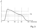
- a measuring means in the form of a strain sensor 1 serves to measure a force FM exerted by the punch 7 on the can blank (see Fig. 3 ) at at least one predetermined position P (see Fig. 3 ) of the working stroke A.
- the strain sensor 1 is arranged on the front knee lever 5 of the toggle press. Exemplary will be in Fig. 3 at exactly one predetermined position P a force FM measured. It is understood that before the position P and / or after the position P further measuring positions can be provided, at which an associated force exerted on the can blank is measured, in which case the position of the working stroke A relative to the die 8 as a function of adjusted to all measured forces.
- the control means 9 compares the measured force FM with a stored, empirically determined desired force and displaces the punch 7 or the working stroke A by suitable control of the servomotor 4 in the direction of the die 8 when the measured force is greater than the desired force , so that the can bottom thickness decreases, and shifts accordingly the punch 7 or the working stroke A by suitably driving the servomotor 4 away from the die 8, when the measured force FM is smaller than the target force, so that the bottom of the box floor increases.
- a rotary encoder 2 For detecting a current position of the working stroke A, a rotary encoder 2 is provided. A full stroke corresponds to a rotation of 360 degrees.
- the strain sensor 1 is mounted on a machined surface, as centrally as possible, on the front toggle lever 5 of the toggle press.
- the rotary encoder 2 sits on a camshaft 6 of the toggle press.
- One complete revolution of the camshaft 6 corresponds to 360 ° of the rotary encoder 2, i. 360 ° of the rotary encoder 2 correspond to a complete working stroke of the toggle press.
- the axial or translational stroke of the punch 7, i. an amplitude of the working stroke is constant.
- the position or position of the punch 7 or working stroke relative to the die 8 can be changed by means of the press wedge 3, which is driven by means of the servomotor 4. If the press wedge 3 is pushed down, the position of the working stroke moves in the direction of the die or die 8 and the bottom of the can becomes thinner. If pushed in accordance with the press wedge 3 up, so the position of the working displacement moves away from the die or the die 8 and the bottom of the can becomes thicker. It is understood that depending on a press type, this behavior may be inverted.
- Fig. 2 shows for clarity a plan view of a section of the in Fig. 1 shown device.
- Fig. 3 shows a force-displacement diagram or force-angle diagram of a means of in the Figures 1 and 2 apparatus shown performed exemplary pressure forming operation.
- the zero point of the rotary encoder 2 is just before the impact of the punch 7 on the can blank.
- the application of force starts at approx. 17 ° and ends at approx. 115 °.
- the predetermined position P of the working stroke A, at which the force exerted by the punch 7 on the can blank force FM is measured, corresponds to approximately 97 °.
- the invention enables a simple and reliable control of a desired can bottom thickness solely by means of force measurement at a predetermined position of the working stroke. A costly immediate measurement of the bottom of the box floor can therefore be omitted.
- Cans or cylinders produced by the pressure forming process can be automatically sorted out or discharged if the measured force (FM) and thus the corresponding bottom thickness is outside a specified tolerance range.
- FM measured force
- a subsequent control step with dedicated bottom thickness measurement can be eliminated altogether, i.
- a fully automated manufacturing process including integrated floor thickness control and sorting cans with incorrect floor thickness can be implemented.
Landscapes
- Engineering & Computer Science (AREA)
- Mechanical Engineering (AREA)
- Automation & Control Theory (AREA)
- Shaping Metal By Deep-Drawing, Or The Like (AREA)
Description
- Die Erfindung betrifft ein Verfahren und eine Vorrichtung zum Herstellen von Dosen aus Dosenrohlingen mittels Druckumformen.
- Dosen werden üblicherweise aus Dosenrohlingen, sogenannten Butzen, mittels Druckumformen hergestellt.
- Die derart hergestellten Dosen müssen eine vorgegebene Dosenbodendicke aufweisen, um beispielsweise einem Fülldruck ausreichend standzuhalten.
- Die
GB 2 310 043 A - Die
US 5,746,122 A zeigt ein Druckumformverfahren, bei dem Drücke bestimmt werden, um eine optimale Fertigungsqualität zu erzielen. Die mittels Drucksensoren gemessenen Kräfte werden in einer Steuer- und Regeleinrichtung ausgewertet, wobei diese in Abhängigkeit von den gemessenen Kräften eine Verstelleinrichtung ansteuert, die eine Koordinate einer Matrize verändert. - Der Erfindung liegt die Aufgabe zugrunde, ein Verfahren und eine Vorrichtung zum Herstellen von Dosen aus Dosenrohlingen mittels Druckumformen zur Verfügung zu stellen, die eine einfache und zuverlässige Einstellung und/oder Regelung einer gewünschten Dosenbodendicke ermöglichen.
- Die Erfindung löst diese Aufgabe durch ein Verfahren nach Anspruch 1 und eine Vorrichtung nach Anspruch 5.
- Das Verfahren dient zum Herstellen von Dosen aus Dosenrohlingen mittels Druckumformen.
- Beim Druckumformen kann es sich um (Kalt-)Rückwärtsfließpressen handeln. Hierbei wird der Werkstoff, beispielsweise Aluminium, unter Einwirkung eines hohen Druckes zum Fließen gebracht. Hierzu wird ein Dosenrohling in einer teilweise geschlossenen Matrize bzw. einem teilweise geschlossenen Gesenk angeordnet und mittels eines Stempels, der in die Matrize eindringt, druckbeaufschlagt. Das Dosenmaterial fließt durch den Spalt zwischen Stempel und (geschlossener) Matrize entgegengesetzt zur Stempelbewegung bzw. zum Stempelarbeitshub, d.h. rückwärts am Stempel entlang.
- Bei dem Druckumform-Vorgang zum Herstellen einer Dose wird folglich der Dosenrohling herkömmlich in eine Matrize eingelegt und anschließend wird mittels eines Stempels eine Kraft auf den Dosenrohling ausgeübt. Der Stempel führt herkömmlich einen, insbesondere rein translatorischen, Arbeitshub aus, dessen Lage (Position, Entfernung) relativ zur Matrize einstellbar ist. Eine Veränderung der Lage des Arbeitshubes relativ zur Matrize verändert die Eindringtiefe des Stempels in die Matrize, wodurch sich die Dosenbodendicke verändert.
- Da es sich bei den bislang genannten Verfahrensschritten um an sich bekannte Verfahrensschritte handelt, sei auch auf die einschlägige Fachliteratur verwiesen, um Wiederholungen zu vermeiden.
- Während eines jeweiligen Druckumform-Vorgangs wird eine durch den Stempel auf den Dosenrohling ausgeübte bzw. bewirkte Kraft oder eine hiermit in Beziehung stehende Kraft an mindestens einer vorgegebenen Position des Arbeitshubes gemessen.
- Die Lage bzw. Position des Arbeitshubes relativ zur Matrize, d.h. die Eindringtiefe des Stempels in die Matrize, wird in Abhängigkeit von der gemessenen Kraft eingestellt bzw. geregelt.
- Der Erfindung liegt die Erkenntnis zugrunde, dass die Dosenbodendicke von der gemessenen Kraft abhängt. Die gemessene Kraft kann daher als Istwert eines geschlossenen Dosenbodendicken-Regelkreises verwendet werden, wobei als Stellgröße die Lage bzw. Position des Arbeitshubes relativ zur Matrize dient.
- Das Verfahren kann weitere folgende Schritte aufweisen: Vergleichen der gemessenen Kraft mit einer vorgebbaren bzw. vorgegebenen Soll-Kraft, die empirisch oder rechnerisch ermittelt werden kann, und Verlagern des Arbeitshubes in Richtung der Matrize, wenn die gemessene Kraft größer als die Soll-Kraft ist, und Verlagern des Arbeitshubes entgegen der Richtung der Matrize bzw. weg von der Matrize, wenn die gemessene Kraft kleiner als die Soll-Kraft ist.
- Die vorgegebene Position kann in einem Bereich zwischen 80% und 90% des Arbeitshubes (in eine Richtung) liegen.
- Mittels des Druckumformvorgangs hergestellte Dosen bzw. Zylinder können automatisch aussortiert bzw. ausgeschleust werden, wenn die gemessene Kraft (FM) und somit die entsprechende Bodendicke außerhalb eines vorgegebenen Toleranzbereichs liegt. Somit kann ein nachfolgender Kontrollschritt mit dediziertem Messen der Bodendicke gänzlich entfallen, d.h. es kann ein vollautomatisierter Herstellungsprozess inklusive integrierter Bodendickenkontrolle und Aussortieren von Dosen mit fehlerhafter Bodendicke implementiert werden.
- Die erfindungsgemäße Vorrichtung ist zur Durchführung des oben genannten Verfahrens ausgebildet.
- Die Vorrichtung weist erfindungsgemäß auf: eine herkömmliche Matrize, in die ein herkömmlicher Dosenrohling einlegbar ist, einen herkömmlichen Stempel zur Ausübung einer Kraft auf den Dosenrohling, wobei der Stempel einen Arbeitshub ausführt, und eine herkömmliche Stelleinrichtung, mittels der die Lage des Arbeitshubes relativ zur Matrize einstellbar ist.
- Die erfindungsgemäße Vorrichtung weist weiter ein Messmittel zum Messen einer durch den Stempel auf den Dosenrohling ausgeübten Kraft an mindestens einer vorgegebenen Position des Arbeitshubes und ein Steuermittel zum automatischen Einstellen der Lage des Arbeitshubes relativ zur Matrize in Abhängigkeit von der gemessenen Kraft auf.
- Die Vorrichtung kann weiter eine Kniehebelpresse aufweisen, wobei das Messmittel ein Dehnungssensor bzw. Dehnungsmesstreifen ist, der auf einem solchen Kniehebel der Kniehebelpresse angeordnet ist, der mit dem Stempel mechanisch gekoppelt ist.
- Die Vorrichtung kann weiter einen Drehwinkelgeber zur Erfassung der momentanen Position des Arbeitshubes aufweisen.
- Die Erfindung wird nachfolgend unter Bezugnahme auf die Zeichnungen beschrieben. Hierbei zeigt schematisch:
- Fig. 1
- ein seitliches Schnittbild einer Vorrichtung zum Herstellen von Dosen aus Dosenrohlingen mittels Druckumformen,
- Fig. 2
- eine Draufsicht auf einen Ausschnitt der in
Fig. 1 gezeigten Vorrichtung und - Fig. 3
- ein Kraft-Weg-Diagramm eines mittels der in den
Figuren 1 und 2 gezeigten Vorrichtung durchgeführten DruckumformVorgangs. -
Fig. 1 zeigt ein seitliches Schnittbild einer Vorrichtung zum Herstellen von Dosen aus Dosenrohlingen mittels Kaltrückwärtsfließpressen. - Die Vorrichtung weist ein herkömmliches Gesenk bzw. eine herkömmliche Matrize 8 auf, in die ein nicht dargestellter Dosenrohling herkömmlich einlegbar ist.
- Weiter ist ein herkömmlicher Stempel 7 zur Ausübung einer Kraft auf den Dosenrohling vorgesehen, wobei der Stempel 7 einen translatorischen bzw. stempelaxialen Arbeitshub A ausführt.
- Zur Erzeugung der notwendigen Umformkräfte ist eine herkömmliche Kniehebelpresse vorgesehen, wobei ein vorderer Kniehebel 5 der Kniehebelpresse mittels einer Kopplungseinrichtung mit dem Stempel 7 mechanisch gekoppelt ist.
- Mittels einer Stelleinrichtung in Form eines Stellmotors 4, der auf einen Presskeil 3 einwirkt, ist die Lage bzw. Entfernung des Stempels 7 bzw. des Arbeitshubes A relativ zur Matrize 8 und somit eine Eindringtiefe des Stempels 7 in die Matrize 8 einstellbar, d.h. mittels der Stelleinrichtung 4 und 3 lässt sich eine Dosenbodendicke einstellen.
- Ein Messmittel in Form eines Dehnungssensors 1 dient zum Messen einer durch den Stempel 7 auf den Dosenrohling ausgeübten Kraft FM (siehe
Fig. 3 ) an mindestens einer vorgegebenen Position P (sieheFig. 3 ) des Arbeitshubes A. Der Dehnungssensor 1 ist auf dem vorderen Kniehebel 5 der Kniehebelpresse angeordnet. Exemplarisch wird inFig. 3 an genau einer vorgegebenen Position P eine Kraft FM gemessen. Es versteht sich, dass vor der Position P und/oder nach der Position P weitere Messpositionen vorgesehen sein können, an denen eine zugehörige auf den Dosenrohling ausgeübte Kraft gemessen wird, wobei für diesen Fall die Lage des Arbeitshubes A relativ zur Matrize 8 in Abhängigkeit von sämtlichen gemessenen Kräften eingestellt wird. - Ein mit dem Dehnungssensor 1 und dem Stellmotor 4 gekoppeltes Steuermittel 9, beispielsweise in Form eines Mikroprozessors, ist zum Einstellen der Lage des Stempels 7 bzw. des Arbeitshubes A relativ zur Matrize 8 in Abhängigkeit von der gemessenen Kraft FM vorgesehen.
- Das Steuermittel 9 vergleicht die gemessene Kraft FM mit einer gespeicherten, empirisch ermittelten Soll-Kraft und verlagert den Stempel 7 bzw. den Arbeitshub A durch geeignetes Ansteuern des Stellmotors 4 in Richtung der Matrize 8, wenn die gemessene Kraft größer als die Soll-Kraft ist, so dass die Dosenbodendicke abnimmt, und verlagert entsprechend den Stempel 7 bzw. den Arbeitshub A durch geeignetes Ansteuern des Stellmotors 4 weg von der Matrize 8, wenn die gemessene Kraft FM kleiner als die Soll-Kraft ist, so dass die Dosenbodendicke zunimmt.
- Zur Erfassung einer momentanen Position des Arbeitshubes A ist ein Drehwinkelgeber 2 vorgesehen. Ein vollständiger Arbeitshub entspricht einer Drehung um 360 Winkelgrad.
- Der Dehnungssensor 1 ist auf einer bearbeiteten Fläche, möglichst mittig, auf dem vorderen Kniehebel 5 der Kniehebelpresse zu montieren.
- Der Drehwinkelgeber 2 sitzt auf einer Kurvenwelle 6 der Kniehebelpresse. Einer vollständigen Umdrehung der Kurvenwelle 6 entsprechen 360° des Drehgebers 2, d.h. 360° des Drehgebers 2 entsprechen einem vollständigen Arbeitshub der Kniehebelpresse.
- Die axiale bzw. translatorische Hubbewegung des Stempels 7, d.h. eine Amplitude des Arbeitshubes, ist konstant. Die Lage bzw. Position des Stempels 7 bzw. Arbeitshubes relativ zur Matrize 8 kann mittels des Presskeils 3, der mittels des Stellmotors 4 angetrieben wird, verändert werden. Wird der Presskeil 3 nach unten geschoben, so verlagert sich die Lage des Arbeitshubes Richtung Matrize bzw. Gesenk 8 und der Boden der Dose wird dünner. Wird entsprechend der Presskeil 3 nach oben geschoben, so verlagert sich die Lage des Arbeitshubes weg von der Matrize bzw. dem Gesenk 8 und der Boden der Dose wird dicker. Es versteht sich, dass in Abhängigkeit von einem Pressentyp dieses Verhalten invertiert sein kann.
-
Fig. 2 zeigt zur Verdeutlichung eine Draufsicht auf einen Ausschnitt der inFig. 1 gezeigten Vorrichtung. -
Fig. 3 zeigt ein Kraft-Weg-Diagramm bzw. Kraft-Winkel-Diagramm eines mittels der in denFiguren 1 und 2 gezeigten Vorrichtung durchgeführten exemplarischen Druckumform-Vorgangs. - Der Nullpunkt des Drehwinkelgebers 2 ist kurz vor dem Auftreffen des Stempels 7 auf den Dosenrohling. Die Kraftbeaufschlagung beginnt bei ca. 17° und endet bei ca. 115°.
- Die vorgegebene Position P des Arbeitshubes A, an der die durch den Stempel 7 auf den Dosenrohling ausgeübte Kraft FM gemessen wird, entspricht ca. 97°.
- Wenn der Dosenboden dicker wird, erhöht sich die Kraft FM. Bei einem dünneren Boden verringert sich die Kraft FM entsprechend.
- Die Erfindung ermöglicht eine einfache und zuverlässige Regelung einer gewünschten Dosenbodendicke allein mittels Kraftmessung an einer vorgegebenen Position des Arbeitshubes. Eine aufwändige unmittelbare Messung der Dosenbodendicke kann daher entfallen.
- Mittels des Druckumformvorgangs hergestellte Dosen bzw. Zylinder können automatisch aussortiert bzw. ausgeschleust werden, wenn die gemessene Kraft (FM) und somit die entsprechende Bodendicke außerhalb eines vorgegebenen Toleranzbereichs liegt. Somit kann ein nachfolgender Kontrollschritt mit dediziertem Messen der Bodendicke gänzlich entfallen, d.h. es kann ein vollautomatisierter Herstellungsprozess inklusive integrierter Bodendickenkontrolle und Aussortieren von Dosen mit fehlerhafter Bodendicke implementiert werden.
Claims (7)
- Verfahren zum Herstellen von Dosen aus Dosenrohlingen mittels Druckumformen,
mit den Schritten:- Ausführen eines Druckumform-Vorgangs zum Herstellen einer Dose, bei dem der Dosenrohling in eine Matrize (8) eingelegt und anschließend mittels eines Stempels (7) eine Kraft auf den Dosenrohling ausgeübt wird, wobei der Stempel (7) einen Arbeitshub (A) ausführt, dessen Lage relativ zur Matrize (8) einstellbar ist,gekennzeichnet durch die Schritte:- Durchführen einer Dosenbodendickenregelung,- wobei als Istwert der Dosenbodendickenregelung eine durch den Stempel (7) auf den Dosenrohling ausgeübte Kraft (FM) an mindestens einer vorgegebenen Position (P) des Arbeitshubes (A) gemessen wird, und- wobei als Stellgröße der Dosenbodendickenregelung die Lage des Arbeitshubes (A) relativ zur Matrize (8) dient, wobei die Lage des Arbeitshubes (A) relativ zur Matrize (8) in Abhängigkeit von der gemessenen Kraft (FM) eingestellt wird. - Verfahren nach Anspruch 1, gekennzeichnet durch die Schritte:- Vergleichen der gemessenen Kraft mit einer Soll-Kraft und- Verlagern des Arbeitshubes (A) in Richtung der Matrize (8), wenn die gemessene Kraft größer als die Soll-Kraft ist, und Verlagern des Arbeitshubes (A) entgegen der Richtung der Matrize (8), wenn die gemessene Kraft kleiner als die Soll-Kraft ist.
- Verfahren nach Anspruch 1 oder 2, dadurch gekennzeichnet, dass die vorgegebene Position (P) in einem Bereich zwischen 80% und 90% des Arbeitshubes (A) liegt.
- Verfahren nach einem der vorhergehenden Ansprüche, dadurch gekennzeichnet, dass Dosen automatisch aussortiert werden, wenn die gemessene Kraft (FM) außerhalb eines vorgegebenen Toleranzbereichs liegt.
- Vorrichtung zur Durchführung des Verfahrens nach einem der Ansprüche 1 bis 4, aufweisend:- eine Matrize (8), in die ein Dosenrohling einlegbar ist,- einen Stempel (7) zur Ausübung einer Kraft auf den Dosenrohling, wobei der Stempel (7) einen Arbeitshub (A) ausführt,- eine Stelleinrichtung (4, 3), mittels der die Lage des Arbeitshubes (A) relativ zur Matrize (8) einstellbar ist,gekennzeichnet durch:- einen Dosenbodendicken-Regelkreises, aufweisend:- ein Messmittel (1) zum Messen einer durch den Stempel (7) auf den Dosenrohling ausgeübten Kraft (FM) an mindestens einer vorgegebenen Position (P) des Arbeitshubes als Istwert für den Dosenbodendicken-Regelkreis und- ein Steuermittel (9) zum Einstellen der Lage des Arbeitshubes (A) relativ zur Matrize (8) in Abhängigkeit von der gemessenen Kraft (FM) als Stellgröße für den Dosenbodendicken-Regelkreis.
- Vorrichtung nach Anspruch 5, gekennzeichnet durch- eine Kniehebelpresse, wobei das Messmittel ein Dehnungssensor (1) ist, der auf einem Kniehebel (5) der Kniehebelpresse angeordnet ist, der mit dem Stempel (7) gekoppelt ist.
- Vorrichtung nach Anspruch 5 oder 6, gekennzeichnet durch- einen Drehwinkelgeber (2) zur Erfassung der Position des Arbeitshubes (8).
Applications Claiming Priority (1)
| Application Number | Priority Date | Filing Date | Title |
|---|---|---|---|
| DE102012212980.4A DE102012212980B4 (de) | 2012-07-24 | 2012-07-24 | Verfahren und Vorrichtung zum Herstellen von Dosen aus Dosenrohlingen mittels Druckumformen |
Publications (2)
| Publication Number | Publication Date |
|---|---|
| EP2689866A1 EP2689866A1 (de) | 2014-01-29 |
| EP2689866B1 true EP2689866B1 (de) | 2017-06-07 |
Family
ID=48874857
Family Applications (1)
| Application Number | Title | Priority Date | Filing Date |
|---|---|---|---|
| EP13177824.3A Not-in-force EP2689866B1 (de) | 2012-07-24 | 2013-07-24 | Verfahren und Vorrichtung zum Herstellen von Dosen aus Dosenrohlingen mittels Druckumformen |
Country Status (2)
| Country | Link |
|---|---|
| EP (1) | EP2689866B1 (de) |
| DE (1) | DE102012212980B4 (de) |
Families Citing this family (2)
| Publication number | Priority date | Publication date | Assignee | Title |
|---|---|---|---|---|
| DE202017007601U1 (de) | 2017-06-20 | 2023-07-03 | Profiroll Technologies GmbH | Umformmaschine |
| DE102017113503A1 (de) * | 2017-06-20 | 2018-12-20 | Profiroll Technologies Gmbh | Umformmaschine und Druckumformverfahren |
Family Cites Families (4)
| Publication number | Priority date | Publication date | Assignee | Title |
|---|---|---|---|---|
| EP0741001B1 (de) * | 1995-05-04 | 2002-02-06 | Gietz AG | Präge-Druck- und Stanzmaschine |
| NL1000657C2 (nl) * | 1995-06-26 | 1996-12-31 | Hoogovens Staal Bv | Matrijs en werkwijze voor het die-necken van een metalen romp. |
| GB9602282D0 (en) * | 1996-02-05 | 1996-04-03 | Newmarket Datasystems Ltd | Apparatus & method for process monitoring |
| DE102007002008A1 (de) * | 2007-01-08 | 2008-07-10 | Lanico-Maschinenbau Otto Niemsch Gmbh | Verschließeinheit für runde und unrunde Verpackungen in Dosenform |
-
2012
- 2012-07-24 DE DE102012212980.4A patent/DE102012212980B4/de not_active Expired - Fee Related
-
2013
- 2013-07-24 EP EP13177824.3A patent/EP2689866B1/de not_active Not-in-force
Also Published As
| Publication number | Publication date |
|---|---|
| DE102012212980B4 (de) | 2014-02-20 |
| EP2689866A1 (de) | 2014-01-29 |
| DE102012212980A1 (de) | 2014-01-30 |
Similar Documents
| Publication | Publication Date | Title |
|---|---|---|
| DE69407520T2 (de) | Verfahren zum verbinden von zwei oder mehreren aufeinanderliegenden blechen und eine vorrichtung zur durchführung dieses verfahrens | |
| EP3383564B1 (de) | Verfahren zur bestimmung der qualität einer fügeverbindung sowie steuerverfahren für ein verbinden einer mehrzahl von blechen mithilfe einer fügevorrichtung | |
| DE102008025074A1 (de) | Durchsetzfügeverfahren | |
| DE60204568T2 (de) | Verfahren zur einstellung der bahn einer abkantpresse | |
| DE102012025047B4 (de) | Überwachungsverfahren für einen Fügeprozess und Fügevorrichtung | |
| EP0403038A2 (de) | Verfahren und Vorrichtung zum Herstellen von masshaltingen Presslingen | |
| EP3274110B1 (de) | Umformwerkzeug und verfahren zur optimierung einer platinenumformung in einem umformwerkzeug | |
| EP0399296B1 (de) | Automatisches Einrichten eines Universalwalzgerüstes nach dessen Umbau auf neue Profilformate | |
| DE102010037849B4 (de) | Verfahren und Vorrichtung zur Herstellung von Faserverbundbauteilen im Infusionsverfahren | |
| EP2361758B1 (de) | Verfahren zur Pressparameteranpassung einer Keramik- oder Metallpulverpresse und Keramik-oder Metallpulverpresse zum Durchführen des Verfahrens | |
| DE102015109805A1 (de) | Herstellen von qualitativ harten Formstoffformen für den Metallguss (Verfahren und Vorrichtung) | |
| DE102018122982B4 (de) | Verfahren und Vorrichtung zur Herstellung von Hohlkörpern aus spritzgegossenem Kunststoffmaterial | |
| EP0353479B1 (de) | Verfahren und Vorrichtung zur Verminderung der Pressenbelastung einer mit Festanschlägen ausgerüsteten Schnittpresse | |
| DE19954310B4 (de) | Verfahren zum schnellen Regeln von Ziehvorgängen in Pressen und hierzu geeignete Ziehpresse | |
| EP3600715A1 (de) | Verfahren zum setzen einer umformtechnisch gefügten verbindung | |
| DE102012212980B4 (de) | Verfahren und Vorrichtung zum Herstellen von Dosen aus Dosenrohlingen mittels Druckumformen | |
| EP3003598B1 (de) | Einstellhilfe für eine fügeeinrichtung mit einem stempel und einem gegenwerkzeug sowie ein verfahren zum einstellen der fügeeinrichtung | |
| DE102011120789A1 (de) | Verfahren zur Bearbeitung und/oder Einstellung eines Platinen- Umformwerkzeuges | |
| DE102012101952B4 (de) | Presse sowie Verfahren zur Herstellung eines Dosenkörpers mit automatischer Einstellung der Bodendicke | |
| EP3814125B1 (de) | Verfahren zum betrieb einer stanzpresse und stanzpressen zum betrieb gemäss den verfahren | |
| DE10135283C2 (de) | Verfahren zum Verpressen von Pulvermaterial | |
| DE1911665A1 (de) | Pulvermetallpresse | |
| DE3244171A1 (de) | Verfahren und vorrichtung zur erfassung einer zwischen zwei gegeneinander bewegbaren maschinenteilen auftretenden kraft | |
| DE10329898A1 (de) | Verfahren und Vorrichtung zum Umformen von Blechplatinen | |
| DE2305283C3 (de) | Verfahren und Vorrichtung zum Messen der bleibenden Durchbiegung eines Werkstückes bei einer Blechbiegepresse |
Legal Events
| Date | Code | Title | Description |
|---|---|---|---|
| PUAI | Public reference made under article 153(3) epc to a published international application that has entered the european phase |
Free format text: ORIGINAL CODE: 0009012 |
|
| AK | Designated contracting states |
Kind code of ref document: A1 Designated state(s): AL AT BE BG CH CY CZ DE DK EE ES FI FR GB GR HR HU IE IS IT LI LT LU LV MC MK MT NL NO PL PT RO RS SE SI SK SM TR |
|
| AX | Request for extension of the european patent |
Extension state: BA ME |
|
| 17P | Request for examination filed |
Effective date: 20140729 |
|
| RBV | Designated contracting states (corrected) |
Designated state(s): AL AT BE BG CH CY CZ DE DK EE ES FI FR GB GR HR HU IE IS IT LI LT LU LV MC MK MT NL NO PL PT RO RS SE SI SK SM TR |
|
| 17Q | First examination report despatched |
Effective date: 20150127 |
|
| GRAP | Despatch of communication of intention to grant a patent |
Free format text: ORIGINAL CODE: EPIDOSNIGR1 |
|
| GRAJ | Information related to disapproval of communication of intention to grant by the applicant or resumption of examination proceedings by the epo deleted |
Free format text: ORIGINAL CODE: EPIDOSDIGR1 |
|
| GRAP | Despatch of communication of intention to grant a patent |
Free format text: ORIGINAL CODE: EPIDOSNIGR1 |
|
| RIC1 | Information provided on ipc code assigned before grant |
Ipc: B21D 51/26 20060101AFI20161110BHEP Ipc: B30B 15/00 20060101ALI20161110BHEP |
|
| INTG | Intention to grant announced |
Effective date: 20161124 |
|
| INTC | Intention to grant announced (deleted) | ||
| INTG | Intention to grant announced |
Effective date: 20161215 |
|
| RIC1 | Information provided on ipc code assigned before grant |
Ipc: B21D 51/26 20060101AFI20161202BHEP Ipc: B30B 15/00 20060101ALI20161202BHEP |
|
| GRAS | Grant fee paid |
Free format text: ORIGINAL CODE: EPIDOSNIGR3 |
|
| AK | Designated contracting states |
Kind code of ref document: B1 Designated state(s): AL AT BE BG CH CY CZ DE DK EE ES FI FR GB GR HR HU IE IS IT LI LT LU LV MC MK MT NL NO PL PT RO RS SE SI SK SM TR |
|
| REG | Reference to a national code |
Ref country code: GB Ref legal event code: FG4D Free format text: NOT ENGLISH |
|
| GRAA | (expected) grant |
Free format text: ORIGINAL CODE: 0009210 |
|
| REG | Reference to a national code |
Ref country code: CH Ref legal event code: EP Ref country code: AT Ref legal event code: REF Ref document number: 898835 Country of ref document: AT Kind code of ref document: T Effective date: 20170615 |
|
| REG | Reference to a national code |
Ref country code: IE Ref legal event code: FG4D Free format text: LANGUAGE OF EP DOCUMENT: GERMAN |
|
| REG | Reference to a national code |
Ref country code: DE Ref legal event code: R096 Ref document number: 502013007421 Country of ref document: DE |
|
| REG | Reference to a national code |
Ref country code: FR Ref legal event code: PLFP Year of fee payment: 5 |
|
| REG | Reference to a national code |
Ref country code: NL Ref legal event code: MP Effective date: 20170607 |
|
| REG | Reference to a national code |
Ref country code: LT Ref legal event code: MG4D |
|
| PG25 | Lapsed in a contracting state [announced via postgrant information from national office to epo] |
Ref country code: GR Free format text: LAPSE BECAUSE OF FAILURE TO SUBMIT A TRANSLATION OF THE DESCRIPTION OR TO PAY THE FEE WITHIN THE PRESCRIBED TIME-LIMIT Effective date: 20170908 Ref country code: ES Free format text: LAPSE BECAUSE OF FAILURE TO SUBMIT A TRANSLATION OF THE DESCRIPTION OR TO PAY THE FEE WITHIN THE PRESCRIBED TIME-LIMIT Effective date: 20170607 Ref country code: HR Free format text: LAPSE BECAUSE OF FAILURE TO SUBMIT A TRANSLATION OF THE DESCRIPTION OR TO PAY THE FEE WITHIN THE PRESCRIBED TIME-LIMIT Effective date: 20170607 Ref country code: LT Free format text: LAPSE BECAUSE OF FAILURE TO SUBMIT A TRANSLATION OF THE DESCRIPTION OR TO PAY THE FEE WITHIN THE PRESCRIBED TIME-LIMIT Effective date: 20170607 Ref country code: NO Free format text: LAPSE BECAUSE OF FAILURE TO SUBMIT A TRANSLATION OF THE DESCRIPTION OR TO PAY THE FEE WITHIN THE PRESCRIBED TIME-LIMIT Effective date: 20170907 Ref country code: FI Free format text: LAPSE BECAUSE OF FAILURE TO SUBMIT A TRANSLATION OF THE DESCRIPTION OR TO PAY THE FEE WITHIN THE PRESCRIBED TIME-LIMIT Effective date: 20170607 |
|
| PG25 | Lapsed in a contracting state [announced via postgrant information from national office to epo] |
Ref country code: BG Free format text: LAPSE BECAUSE OF FAILURE TO SUBMIT A TRANSLATION OF THE DESCRIPTION OR TO PAY THE FEE WITHIN THE PRESCRIBED TIME-LIMIT Effective date: 20170907 Ref country code: NL Free format text: LAPSE BECAUSE OF FAILURE TO SUBMIT A TRANSLATION OF THE DESCRIPTION OR TO PAY THE FEE WITHIN THE PRESCRIBED TIME-LIMIT Effective date: 20170607 Ref country code: RS Free format text: LAPSE BECAUSE OF FAILURE TO SUBMIT A TRANSLATION OF THE DESCRIPTION OR TO PAY THE FEE WITHIN THE PRESCRIBED TIME-LIMIT Effective date: 20170607 Ref country code: SE Free format text: LAPSE BECAUSE OF FAILURE TO SUBMIT A TRANSLATION OF THE DESCRIPTION OR TO PAY THE FEE WITHIN THE PRESCRIBED TIME-LIMIT Effective date: 20170607 Ref country code: LV Free format text: LAPSE BECAUSE OF FAILURE TO SUBMIT A TRANSLATION OF THE DESCRIPTION OR TO PAY THE FEE WITHIN THE PRESCRIBED TIME-LIMIT Effective date: 20170607 |
|
| PG25 | Lapsed in a contracting state [announced via postgrant information from national office to epo] |
Ref country code: RO Free format text: LAPSE BECAUSE OF FAILURE TO SUBMIT A TRANSLATION OF THE DESCRIPTION OR TO PAY THE FEE WITHIN THE PRESCRIBED TIME-LIMIT Effective date: 20170607 Ref country code: CZ Free format text: LAPSE BECAUSE OF FAILURE TO SUBMIT A TRANSLATION OF THE DESCRIPTION OR TO PAY THE FEE WITHIN THE PRESCRIBED TIME-LIMIT Effective date: 20170607 Ref country code: SK Free format text: LAPSE BECAUSE OF FAILURE TO SUBMIT A TRANSLATION OF THE DESCRIPTION OR TO PAY THE FEE WITHIN THE PRESCRIBED TIME-LIMIT Effective date: 20170607 Ref country code: EE Free format text: LAPSE BECAUSE OF FAILURE TO SUBMIT A TRANSLATION OF THE DESCRIPTION OR TO PAY THE FEE WITHIN THE PRESCRIBED TIME-LIMIT Effective date: 20170607 |
|
| PG25 | Lapsed in a contracting state [announced via postgrant information from national office to epo] |
Ref country code: IS Free format text: LAPSE BECAUSE OF FAILURE TO SUBMIT A TRANSLATION OF THE DESCRIPTION OR TO PAY THE FEE WITHIN THE PRESCRIBED TIME-LIMIT Effective date: 20171007 Ref country code: SM Free format text: LAPSE BECAUSE OF FAILURE TO SUBMIT A TRANSLATION OF THE DESCRIPTION OR TO PAY THE FEE WITHIN THE PRESCRIBED TIME-LIMIT Effective date: 20170607 Ref country code: PL Free format text: LAPSE BECAUSE OF FAILURE TO SUBMIT A TRANSLATION OF THE DESCRIPTION OR TO PAY THE FEE WITHIN THE PRESCRIBED TIME-LIMIT Effective date: 20170607 Ref country code: IT Free format text: LAPSE BECAUSE OF FAILURE TO SUBMIT A TRANSLATION OF THE DESCRIPTION OR TO PAY THE FEE WITHIN THE PRESCRIBED TIME-LIMIT Effective date: 20170607 |
|
| REG | Reference to a national code |
Ref country code: CH Ref legal event code: PL |
|
| REG | Reference to a national code |
Ref country code: DE Ref legal event code: R097 Ref document number: 502013007421 Country of ref document: DE |
|
| PG25 | Lapsed in a contracting state [announced via postgrant information from national office to epo] |
Ref country code: MC Free format text: LAPSE BECAUSE OF FAILURE TO SUBMIT A TRANSLATION OF THE DESCRIPTION OR TO PAY THE FEE WITHIN THE PRESCRIBED TIME-LIMIT Effective date: 20170607 |
|
| PLBE | No opposition filed within time limit |
Free format text: ORIGINAL CODE: 0009261 |
|
| STAA | Information on the status of an ep patent application or granted ep patent |
Free format text: STATUS: NO OPPOSITION FILED WITHIN TIME LIMIT |
|
| REG | Reference to a national code |
Ref country code: IE Ref legal event code: MM4A |
|
| PG25 | Lapsed in a contracting state [announced via postgrant information from national office to epo] |
Ref country code: CH Free format text: LAPSE BECAUSE OF NON-PAYMENT OF DUE FEES Effective date: 20170731 Ref country code: LI Free format text: LAPSE BECAUSE OF NON-PAYMENT OF DUE FEES Effective date: 20170731 Ref country code: DK Free format text: LAPSE BECAUSE OF FAILURE TO SUBMIT A TRANSLATION OF THE DESCRIPTION OR TO PAY THE FEE WITHIN THE PRESCRIBED TIME-LIMIT Effective date: 20170607 Ref country code: IE Free format text: LAPSE BECAUSE OF NON-PAYMENT OF DUE FEES Effective date: 20170724 |
|
| 26N | No opposition filed |
Effective date: 20180308 |
|
| GBPC | Gb: european patent ceased through non-payment of renewal fee |
Effective date: 20170907 |
|
| PG25 | Lapsed in a contracting state [announced via postgrant information from national office to epo] |
Ref country code: SI Free format text: LAPSE BECAUSE OF FAILURE TO SUBMIT A TRANSLATION OF THE DESCRIPTION OR TO PAY THE FEE WITHIN THE PRESCRIBED TIME-LIMIT Effective date: 20170607 |
|
| REG | Reference to a national code |
Ref country code: BE Ref legal event code: MM Effective date: 20170731 |
|
| PG25 | Lapsed in a contracting state [announced via postgrant information from national office to epo] |
Ref country code: LU Free format text: LAPSE BECAUSE OF NON-PAYMENT OF DUE FEES Effective date: 20170724 |
|
| REG | Reference to a national code |
Ref country code: FR Ref legal event code: PLFP Year of fee payment: 6 |
|
| PG25 | Lapsed in a contracting state [announced via postgrant information from national office to epo] |
Ref country code: GB Free format text: LAPSE BECAUSE OF NON-PAYMENT OF DUE FEES Effective date: 20170907 |
|
| PG25 | Lapsed in a contracting state [announced via postgrant information from national office to epo] |
Ref country code: BE Free format text: LAPSE BECAUSE OF NON-PAYMENT OF DUE FEES Effective date: 20170731 |
|
| PG25 | Lapsed in a contracting state [announced via postgrant information from national office to epo] |
Ref country code: MT Free format text: LAPSE BECAUSE OF FAILURE TO SUBMIT A TRANSLATION OF THE DESCRIPTION OR TO PAY THE FEE WITHIN THE PRESCRIBED TIME-LIMIT Effective date: 20170607 |
|
| PG25 | Lapsed in a contracting state [announced via postgrant information from national office to epo] |
Ref country code: HU Free format text: LAPSE BECAUSE OF FAILURE TO SUBMIT A TRANSLATION OF THE DESCRIPTION OR TO PAY THE FEE WITHIN THE PRESCRIBED TIME-LIMIT; INVALID AB INITIO Effective date: 20130724 |
|
| REG | Reference to a national code |
Ref country code: AT Ref legal event code: MM01 Ref document number: 898835 Country of ref document: AT Kind code of ref document: T Effective date: 20180724 |
|
| PG25 | Lapsed in a contracting state [announced via postgrant information from national office to epo] |
Ref country code: CY Free format text: LAPSE BECAUSE OF NON-PAYMENT OF DUE FEES Effective date: 20170607 |
|
| PG25 | Lapsed in a contracting state [announced via postgrant information from national office to epo] |
Ref country code: MK Free format text: LAPSE BECAUSE OF FAILURE TO SUBMIT A TRANSLATION OF THE DESCRIPTION OR TO PAY THE FEE WITHIN THE PRESCRIBED TIME-LIMIT Effective date: 20170607 |
|
| PG25 | Lapsed in a contracting state [announced via postgrant information from national office to epo] |
Ref country code: AT Free format text: LAPSE BECAUSE OF NON-PAYMENT OF DUE FEES Effective date: 20180724 |
|
| PG25 | Lapsed in a contracting state [announced via postgrant information from national office to epo] |
Ref country code: TR Free format text: LAPSE BECAUSE OF FAILURE TO SUBMIT A TRANSLATION OF THE DESCRIPTION OR TO PAY THE FEE WITHIN THE PRESCRIBED TIME-LIMIT Effective date: 20170607 |
|
| PG25 | Lapsed in a contracting state [announced via postgrant information from national office to epo] |
Ref country code: PT Free format text: LAPSE BECAUSE OF FAILURE TO SUBMIT A TRANSLATION OF THE DESCRIPTION OR TO PAY THE FEE WITHIN THE PRESCRIBED TIME-LIMIT Effective date: 20170607 |
|
| PG25 | Lapsed in a contracting state [announced via postgrant information from national office to epo] |
Ref country code: AL Free format text: LAPSE BECAUSE OF FAILURE TO SUBMIT A TRANSLATION OF THE DESCRIPTION OR TO PAY THE FEE WITHIN THE PRESCRIBED TIME-LIMIT Effective date: 20170607 |
|
| PGFP | Annual fee paid to national office [announced via postgrant information from national office to epo] |
Ref country code: FR Payment date: 20210722 Year of fee payment: 9 |
|
| PGFP | Annual fee paid to national office [announced via postgrant information from national office to epo] |
Ref country code: DE Payment date: 20210722 Year of fee payment: 9 |
|
| REG | Reference to a national code |
Ref country code: DE Ref legal event code: R119 Ref document number: 502013007421 Country of ref document: DE |
|
| PG25 | Lapsed in a contracting state [announced via postgrant information from national office to epo] |
Ref country code: FR Free format text: LAPSE BECAUSE OF NON-PAYMENT OF DUE FEES Effective date: 20220731 |
|
| PG25 | Lapsed in a contracting state [announced via postgrant information from national office to epo] |
Ref country code: DE Free format text: LAPSE BECAUSE OF NON-PAYMENT OF DUE FEES Effective date: 20230201 |