EP2687650B1 - Baupaneel mit einer Einrichtung zur Verbindung mit wenigstens einem weiteren Baupaneel auf einem Untergrund - Google Patents
Baupaneel mit einer Einrichtung zur Verbindung mit wenigstens einem weiteren Baupaneel auf einem Untergrund Download PDFInfo
- Publication number
- EP2687650B1 EP2687650B1 EP12005281.6A EP12005281A EP2687650B1 EP 2687650 B1 EP2687650 B1 EP 2687650B1 EP 12005281 A EP12005281 A EP 12005281A EP 2687650 B1 EP2687650 B1 EP 2687650B1
- Authority
- EP
- European Patent Office
- Prior art keywords
- connector
- groove
- construction panel
- profile
- head piece
- Prior art date
- Legal status (The legal status is an assumption and is not a legal conclusion. Google has not performed a legal analysis and makes no representation as to the accuracy of the status listed.)
- Active
Links
Images


Classifications
-
- E—FIXED CONSTRUCTIONS
- E04—BUILDING
- E04F—FINISHING WORK ON BUILDINGS, e.g. STAIRS, FLOORS
- E04F15/00—Flooring
- E04F15/02—Flooring or floor layers composed of a number of similar elements
- E04F15/02038—Flooring or floor layers composed of a number of similar elements characterised by tongue and groove connections between neighbouring flooring elements
-
- E—FIXED CONSTRUCTIONS
- E04—BUILDING
- E04F—FINISHING WORK ON BUILDINGS, e.g. STAIRS, FLOORS
- E04F2201/00—Joining sheets or plates or panels
- E04F2201/01—Joining sheets, plates or panels with edges in abutting relationship
- E04F2201/0138—Joining sheets, plates or panels with edges in abutting relationship by moving the sheets, plates or panels perpendicular to the main plane
- E04F2201/0146—Joining sheets, plates or panels with edges in abutting relationship by moving the sheets, plates or panels perpendicular to the main plane with snap action of the edge connectors
-
- E—FIXED CONSTRUCTIONS
- E04—BUILDING
- E04F—FINISHING WORK ON BUILDINGS, e.g. STAIRS, FLOORS
- E04F2201/00—Joining sheets or plates or panels
- E04F2201/05—Separate connectors or inserts, e.g. pegs, pins, keys or strips
- E04F2201/0523—Separate tongues; Interlocking keys, e.g. joining mouldings of circular, square or rectangular shape
- E04F2201/0535—Separate tongues; Interlocking keys, e.g. joining mouldings of circular, square or rectangular shape adapted for snap locking
-
- E—FIXED CONSTRUCTIONS
- E04—BUILDING
- E04F—FINISHING WORK ON BUILDINGS, e.g. STAIRS, FLOORS
- E04F2201/00—Joining sheets or plates or panels
- E04F2201/05—Separate connectors or inserts, e.g. pegs, pins, keys or strips
- E04F2201/0523—Separate tongues; Interlocking keys, e.g. joining mouldings of circular, square or rectangular shape
- E04F2201/0564—Separate tongues; Interlocking keys, e.g. joining mouldings of circular, square or rectangular shape depending on the use of specific materials
- E04F2201/0588—Separate tongues; Interlocking keys, e.g. joining mouldings of circular, square or rectangular shape depending on the use of specific materials of organic plastics with or without reinforcements or filling materials
Definitions
- FIG. 5 To derive an anchor-like, consisting of two parts connector, in which a projecting over a side surface of a panel center web, called punch, engages in an inner space of a pressed into a groove of a second panel in C-shaped head.
- the profiled side surfaces of the two interconnected panels extend substantially obliquely to the tread surface of the panels, wherein the coupled parts of the connector are directed perpendicular to the side surfaces.
- Both parts of the connector are constructed mirror-symmetrically to its longitudinal axis.
- a disadvantage of a thus configured panel connection with two-piece connector according to Fig. 5 is that a subsequent separation of the interconnected floor panels is not feasible. Also, a connection of the floor panels together or their laying on a surface seems to be problematic because mounting in the horizontal direction using the known impact block impossible and mounting with pivotal movement is particularly difficult.
- the US 2011/173914 A1 relates to a set of panels, preferably of floor panels, comprising a first panel and at least one second panel each having a top and a bottom, the first panel having on one edge a first retaining profile with a hook directed towards the top, the second panel one edge has a second retaining profile with a hook directed towards the underside, the first retaining profile and the second half profile can be connected by a relative movement directed perpendicularly to a laying plane, and wherein a separate clip is provided which has a clip head, a clip body and a clip foot.
- the set of panels is characterized in that in a laying of the clip of the clip foot is firmly connected to the first holding profile and the clip between the clip body and clip foot has a deformation area, wherein the clip head in the relative movement of the holding profiles of the second holding profile in a Clip evasive groove of the first holding profile is pressed while doing first an opening, the closing or locking rotational movement opposite rotational movement.
- the closing rotational movement of the clip head is not initiated by a pressure of the second holding profile on the clip foot.
- the clip foot is firmly connected to the first holding profile in the laying position of the clip.
- the laying position of the clip is the position occupied by the clip before the holding profiles are connected to each other by relative movement perpendicular to the laying plane.
- the laying is already set in the production process in the factory, so before the panels are delivered to retailers and customers.
- the invention relates to a method for inserting the separate clip in a simple manner in a holding profile.
- the applicant of the present invention discloses a floor panel with a device for connection to at least one further floor panel of the same kind on a substrate, wherein the floor panels respectively opposite a first and a second profiled side surface, on each of which an abutment surface is arranged, which is perpendicular to a Tread surface or a base surface of the floor panel, the impact surface merges into a groove parallel to the tread along the side surface extending groove which is limited to the tread from a groove edge, protrudes beyond the abutment surface a locking arm having a bottom and in a tread surface , Runs approximately trapezoidal lip, which in turn has an inner surface facing the groove, in which in the groove an elongated, at least partially flexible, separate connector is inserted, which in the installed state with the side surface of an opposite Floor panel cooperates, wherein the connector in the undeformed state has approximately a gutter-shaped cross-section and has a curved wall, the wall with a part-cylindrical inner surface
- the groove has a flat groove rear wall offset from the abutment surface, wherein the head piece adjoins a flexible groove Leg is arranged of the connector, so that when joining floor panels, the head piece can be pivoted towards Nutrückwand, the inner surface of the lip is undercut the bottom, so that the foot with its side surface and with its footprint in einmont investigating state of the connector said inner surface and contacted the bottom of the locking arm before and after the joining of the two floor panels.
- the WO 2010/082171 A2 describes a floor panel comprising coupling parts on at least two opposite sides, in the form of a male coupling part or a female coupling part, which allow two such floor panels to be joined together at said sides by one of these floor panels with the associated male coupling part by means of a Downward movement is mounted in the female coupling part of the other floor panel, thereby at least one lock in the horizontal direction is obtained.
- the floor panels are equipped with a so-called "push-lock” system, which comprises either fixed or not firmly fixed, but separately realized insert.
- the Zielsetzun the Erfidnung of WO 2010/082171 A2 is to bring about further optimization of push-lock systems in floor panels
- the object of the invention is to develop an alternative generic device for connecting polygonal, plate-shaped building panels together with the help of separate connectors that do not act like a rock and whose hold on the building panel are safe and stable.
- the building panel which is pivoted down against the already laid down, referred to as Gegenpaneel.
- the terms such as “top”, “top”, “bottom”, “bottom”, “below”, “above” etc. refer to the laid on a foundation building panels, as shown in the drawing.
- the separate connector is referred to as a profile.
- the fourth contact surface according to the invention by a standing down from the profile, resilient tongue is formed, which presses in the inserted state against the lower, sloping groove flank of the first groove , As a result, an even more stable position of the accommodated in the seat profile is achieved.
- At the bottom of the locking arm is advantageously at least one groove parallel to the groove incorporated, which is preferably approximately in the center of the bottom, in any case outside the lower inclined groove flank.
- the lower part of the inserted profile so its base part can be supported.
- the einmont Arthur profile according to the invention therefore applies the principle of at least three contact surfaces of this profile with the lower building panel, namely with the inclined inner surface of the lip, with the bottom of the locking arm and with the upper groove flank of the first groove.
- This set profile sits securely on the side surface of the lower building panel and has little chance to solve independently.
- the device according to the invention may be approximately those which includes a so-called hook connection, in which normally the hook connection forming parts: Lippe on the locking arm and directed to the ground locking element of the Gegenpaneels should be tightly hooked together and the abutting surfaces of the two building panels are to be brought into surface contact with each other to secure the locking of the building panels in the horizontal direction.
- hook connection in which normally the hook connection forming parts: Lippe on the locking arm and directed to the ground locking element of the Gegenpaneels should be tightly hooked together and the abutting surfaces of the two building panels are to be brought into surface contact with each other to secure the locking of the building panels in the horizontal direction.
- the separate connector according to the invention is made of plastic.
- plastics for the connector are thermoplastics, such as polyethylene (PE), polypropylene (PP), polystyrene (PS), polyamides (PA), polycarbonates (PC), polyethylene terephthalate (PET), etc., and so-called engineering plastics, such as styrene copolymers ( ABS), polyamides (PA), polycarbonates (PC), polyethylene terephthalate (PET), polymethylmethacrylate (PMMA), polyoxymethylene (POM), fluoroplastics (Teflon), polyurethanes (PUR) in question.
- PE polyethylene
- PP polypropylene
- PS polystyrene
- PA polyamides
- PC polycarbonates
- PET polyethylene terephthalate
- engineering plastics such as styrene copolymers (AB), polyamides (PA), polycarbonates (PC), polyethylene terephthalate (PET), polymethylmethacrylate
- the foot of the profile may be web-shaped and / or solid, wherein it is of crucial importance that this has an inwardly inclined side surface which is at least partially in contact with the inner surface of the lip - in the inserted state.
- the angle of inclination of the side surface of the foot to its footprint may correspond to said sharp angle at the lip. If the inner surface of the lip is arranged at right angles to the bottom of the locking arm or to the base surface of the building panel, the foot can press with its lower part against the said inner surface.
- the foot and the lower part of the mounted connector almost form-fitting, before and after the lowering of the Gegenpaneels rest on the locking arm.
- the connector may have at least one outwardly extending projection extending in the longitudinal direction of the connector in a transition region of its base part to the movable leg.
- the projection may be in the inserted state of the connector in contact with the groove flank of the second groove.
- the profile can also be made of so-called integral plastics.
- a profile may, for example, have a hard foot and a relatively soft leg adjoining the head piece.
- the head piece and the foot can be made stiffer than the legal material of the profile.
- the profile can have smooth and / or roughened surfaces.
- the profile can be made of metal, wood material or composite.
- the profile may be elastically deformable at least in its leg region.
- the elasticity of the profile may be assisted by corresponding constrictions or gentle transitions of the leg to the foot.
- the head piece may have a strip-shaped, planar, in the inserted state of the first groove flank facing pressure surface, which in turn in a - in cross-section of the profile seen - downward, oblique or rounded sliding surface continues.
- the first, upper groove flank of the groove for receiving the profile runs parallel and the second, lower groove flank obliquely to the useful or base surface of the building panel, wherein the lower groove flank merges into the bottom of the locking arm.
- the two groove flanks close to a perpendicular to the effective surface arranged groove bottom of said groove. So configured groove has enough space for pivoting the head piece.
- the flat pressure surface of the head piece remains in the non-caused by the lowering counter panel, tensioned state in surface contact with the upper groove flank or presses against them.
- the bottom of the locking arm is preferably parallel to the base surface and then forms a support surface for the foot and for the lower part of the wall of the connector.
- a flat or stepped floor is suitable.
- the head piece can when turning down the building panel in the direction of the floor of the already laid building panel a rotary motion to exercise the trough or a gradation of the bottom of the locking arm.
- the leg of the profile is pivoted.
- the foot of the connector can remain immobile in its position on the inner surface of the lip and the base part of the profile.
- the profiles can be pressed into the existing groove of the building panel manually or mechanically or with the aid of an automatic machine.
- the building panels provided with the profiles can be stored and distributed in this form.
- the profile is made of plastic, it can be cheaply made available as a mass-produced article.
- the profiles according to the invention are essentially intended for the narrow edges of the building panels. However, even in the longer side surfaces of the building panels may be integrated if they are adapted to the separate connector accordingly.
- a pressure surface arranged obliquely opposite the useful surface is introduced on the locking element located on the counter panel, with which pressure is exerted on the flat pressure surface, but especially on the rounded or bevelled sliding surface of the head piece.
- the oblique pressing surface of the downward locking element is at an angle ⁇ 45 °, preferably 60 ° relative to the effective area. This angular size ensures optimum sliding of the locking element on the head piece, without the head piece can fall out of the seat.
- the rounded surface of the locking element can be set back in relation to the upper abutment surface of the building panel Pass over obliquely, such that a sharp, approximately V-shaped transition for receiving the head piece is formed.
- the head piece can also engage in a groove of the structural element carrying the locking element.
- the groove is approximately rectangular or trapezoidal. It is advantageous that the rounded surface of the locking element passes over an obliquely or perpendicularly arranged with respect to the useful surface, flat surface in the downwardly open recess of the locking element supporting the building panel.
- a strip-shaped inner surface of the upper part of the foot can be provided, which is compatible with the said flat surface.
- the building panels can be made of plastic, metal, wood-based material, paper or other renewable raw materials, such as cork.
- the building panels can be made in solid or layered construction, such as known HDF or MDF panels, and have a wood or tile decor, which is covered with at least one layer of a transparent or translucent synthetic resin.
- the building panels may be equipped with antibacterial and / or fire retardants.
- the building panels can be used as floor panels, as wall cladding panels or as furniture parts.
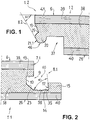
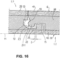
- FIGS. 1, 2 and 16 show two building panels 1.1, 1.2 before and after the pivoting down of the building panel 1.2 (Gegenpaneel) in the direction of the substrate 11, to which the building panel 1.1 is already laid. Characteristic of the figures is the lack of a separate connector, which will be described in detail below.
- the two building panels 1.1, 1.2 each consist of a wear layer 39, a bottom layer 40 and an intermediate core layer 38 of wood material.
- the wear layer 39 is provided with a decorative layer 41, the surface of which forms a step or useful surface 6.
- the bottom layer 40 in turn has a base surface 11 facing the base surface 26.
- the building panel 1.1 is characterized by a profiled, through the utility and base surfaces 6; 26 limited side surface 8.1, comprising an abutment surface 7.1, a recessed relative to the abutment surface, the first groove 9 and a projecting beyond the abutment surface 7.1 locking arm 14 with an upwardly projecting lip 15th
- the first groove 9 is polygonal in cross-section and has a relation to the abutment surface 7.1 recessed groove bottom 10 which is arranged parallel to the impact surface 7.1 and in an upper, plane-parallel to the effective surface 6 extending groove flank 13 and an obliquely directed lower groove flank 23 expires.
- the latter in turn merges into a bottom 35 of the locking arm 14 lying parallel to the base surface 26, wherein a depression 36 extending along the side surface 8.1 in the middle of the bottom 35 is milled out.
- the lip 15 of the locking arm 14 is trapezoidal and tapers in the direction of the bottom layer 40 such that an inner surface 17 inclined at an acute angle ⁇ to the bottom 35 is formed on the lip.
- the angle ⁇ in the present case is between 80 ° and 85 ° and can vary.
- Fig. 1 is formed from the bottom 35 of the locking arm 14, of the inner surface 17 of the lip 15 and of the first groove 9 and of its upper groove flank 13, a seat 60 for accommodating the connector.
- the building panel 1.2 is characterized by a profiled, limited by the tread and base surfaces 6, 26 side surface 8.2, comprising an abutment surface 7.2, a relation to the abutment surface 7.2 recessed slope 19 and a downwardly directed locking element 20.
- the slope 19 forms together with the locking member 20 has a deep, sharp, V-shaped transition 25th
- a pressing surface 21.1 is milled, which forms an acute angle with the effective surface 6 and is arranged approximately parallel to the slope 19.
- the sharp angle is preferably 60 °.
- the locking element 20 connects to a downwardly open recess 37 for receiving the lip 15 of the building panel 1.1.
- Fig. 16 is a relatively wide gap S between the locking member 20 and the lip 15 to see when the two abutting surfaces 7.1, 7.2 contact each other.
- the building panels 1.1, 1.2 are locked together neither in the horizontal, nor in the vertical direction.
- FIG. 7 A similar position of laid on the substrate 11 building panels 1.1, 1.2 is the Fig. 7 refer to. However, here a separate connector 2.1 (profile) is used, such that the gap S (see. Fig. 16 ) is completely filled by a web-shaped foot 12.1 of the profile.
- the approximately gutter-shaped profile 2.1 (see. FIGS. 8 and 9 ) has a cross-section Q1, on which a part-cylindrical inner surface 4, an equally part-cylindrical outer surface 28, a head piece 5.1 and the foot can be seen 12.1.
- the inner and outer surfaces 4, 28 define a channel-shaped wall 3, which extends from the head piece 5.1 to the foot 12.1.
- FIG. 9 Profile 2.1 shown is relatively short and therefore intended for the narrow sides of the building panels. Its length L corresponds essentially to the extent of the narrow side or is slightly smaller.
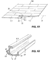
- An in Fig. 61 schematically indicated floor 34 is composed of several building panels 1.1, 1.2 described above, which are locked at their narrow sides on the separate connector and on the long sides via conventional, not shown tongue and groove connections.
- the foot 12.1 has an inclined side surface 24, the angle of inclination of the angle ⁇ (see. Fig. 2 ) is equal to. Furthermore, the foot 12.1 has a base 27 and an elongate upper edge 16 opposite the base 27, which adjoins the part-cylindrical inner surface 4.
- a feature of the head piece 5.1 is its upper pressure surface 18, which is bounded on the inside by a further oblique sliding surface 22.
- the pressed into the building panel 1.1 profile 2.1 is also in FIGS. 3 and 4 shown.
- the head piece 5.1 is in contact with the upper groove flank 13 and protrudes beyond the impact surface 7.1.
- the foot 12.1 is supported with its base 27 at the bottom 35 and with its side surface 24 against the inner surface 17 of the lip 15.
- the wall 3 in turn is supported with its arcuate, lower base part 42 on the trough 36 (see. Fig. 3 ). In this way, the profile 2.1 is fixed to the building panel 1.1 and secured against falling out of the seat 60.
- leg 43 of the wall 3 is flexible. Since the leg 43 carries the head piece 5.1, the latter is also pivotable relative to the base part 42 or rotatably arranged.
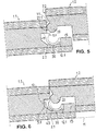
- FIGS. 5, 6 and 56 is shown the pivoting down of the Schmidtpaneels 1.2 on the substrate 11.
- the Schmidtpaneel is about the pivot axis A (see. Fig. 61 ) turned.
- the locking element 20 moves down. It slides over the abutment surface 7.1 of the already laid building panel 1.1 until it abuts with its oblique pressure surface 21 against the head piece 5.1 (see. FIGS. 5 and 6 ). Thereafter, the locking member 20 slides with its Andschreibfiguration 21 over in Fig. 8 shown pressure and sliding surfaces 22, 18 of the head piece, until it is pivoted in the direction of groove bottom 10 and enters the in Fig. 7 shown locking position in which the head piece 5.1 in the v-shaped transition 25 of the slope 19 to the locking element 20.
- the profile is 2.1 when pivoting down the Jacobishaweels 1.2 in the direction of the bottom 35 of the already laid building panel 1.1 torsion, in which the head piece 5.1 is gradually rotated so that first one of the pivot axis A of the building panel facing end 31 and then a second end 32 of the profile completely under the upper groove edge 13 pass.
- Torsion is to be understood in the present case, the distortion of only a portion of the profile, namely the leg 43 and the head piece 5.1, while the foot 12.1 remains immobile in its position.
- the Fig. 10 shows a connector 2.2, which is similar to the connector 2.1 is constructed with the difference that instead of a web-shaped a solid foot 30 is provided.
- This profile shows a cross-section Q2, in which the footprint 27 of the solid foot 30 extends to the base part 42.
- the profile 2.2 can be used instead of the profile 2.1 (not shown).
- FIG. 11 Another similar profile embodiment (reference number 2.3) shows a cross section Q3 according to Fig. 11 ,
- the wall 3 has at its central segment, ie at its base part 42, a flat lower surface 29.
- An unillustrated bottom of the locking arm 14 has an adapted surface (not shown) for the profile 2.3.
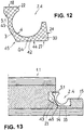
- the Fig. 12 shows a cross section Q4 of another profile 2.4, in which the massive foot 30 on the lower base part 42 of the profile adjoins the arcuate, pivotable leg 43, such that the lower, flat base 27 extends to said leg 43.
- the profile 2.4 is placed with its base 27 on the flat bottom 35 of the locking arm 14.
- the width of the bottom 35 is equal to the base 27.
- the leg 43 is pivotable about a transition region 45 of the profile, which corresponds to the transition of the bottom 35 in the inclined groove flank 23.
- the Fig. 14 shows a cross section Q5 of another profile 2.5, which 2.4 is almost identical to the profile.
- the profile 2.5 is stepped in its transition region 45 to the leg 43.
- the base part 42 of the profile 2.5 has a flat, lower outer surface 44, which extends between the side surface 24 of the lip 15 and a gradation 51 of the wall 3.
- the gradation 51 on the profile 2.5 matches a relatively low groove flank 33.1 of a groove 61 incorporated on the bottom of the locking arm 14 (cf. Fig. 15 ).
- the connector inserted into the groove 61 2.5 presses with its head piece 5.1 against the upper groove flank 13 of the first groove 9. In this way, the connector 2.5 is placed securely in place in the seat of the building panel 1.1 while leaving the required mobility of the head piece 5.1 supporting leg 43rd ,
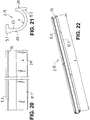
- the Fig. 18 shows a further cross section (reference numeral Q15) of a profile 2.15, in which a further development of the in Fig. 8 represented Profile 2.8 acts.
- the part-cylindrical inner surface 4 of the profile 2.15 goes from the upper edge 16 of the foot 12.1 starting in a flat, reaching to the head piece 5.1 surface portion 63 on.
- the head piece 5.1 is bevelled at both ends 31, 32 of the profile 2.7 respectively, resulting in an insertion edge 49.1, 49.2.
- the profile 2.15 is also in FIGS. 20, 21 and 22 shown.
- a free inner edge 75 arranged on the head piece 5.1 extends in a straight line along the overall length L of the connector and has no introduction edges. Otherwise the profile is with the in FIGS. 17 to 19 shown identical.
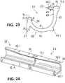
- a cross-section Q6 of another profile 2.6 is shown.
- the foot 12.4 has two thickness dimensions: a thickness a in the upper edge region and a smaller thickness b in the lower, ending with the base surface 27 area.
- the head piece 5.2 has the aforementioned pressure surface 18 and sliding surface 22, but is on both ends 31, 32 of the profile with bevelled lead edges 49.1, 49.2 (see. Fig. 24 ) Mistake.
- the upper, planar pressure surface 18 merges into the sliding surface 22 via a slightly sloping section 76.
- the profile 2.6 has an outwardly projecting, running in the longitudinal direction of the profile, bead-like projection 48.1, which is located in a transition region 47 of the base member 42 to the movable leg 43.
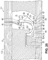
- Fig. 25 shows the projection 48.1 in the inserted state in contact with the bottom 35 of the locking arm 14 and with a perpendicular to the bottom 35 arranged, relatively low groove flank 33.2 of a groove 62.
- the groove 62 is defined by said groove flank 33.2, the inner surface 17 of the lip 15 and the bottom 35 with the trough 36.
- the locking element 20 (see. Fig. 25 ) is bounded by the inclined pressing surface 21.1, a subsequent to the pressing surface 21.1, perpendicular to the effective surface 6, second pressing surface 21.2 and bounded by an inclined support surface 64 on which the head piece 5.2 is supported with its lower surface 65.
- the inclined support surface 64 forms, together with the slope 19, an asymmetrical, V-shaped groove 66, into which the head piece 5.2 is inserted such that it with its pressure surface 18, the upper groove flank 13 of the first groove 9 and with its lower pressure surface 65, the inclined Support surface 64 contacted.
- the planar surface portion 63 of the leg 43 is in contact with the pressing surface 21.2 of the locking element 20 (after the introduction of the locking element 20; Fig. 25 ).
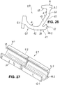
- Fig. 26 is a cross-section Q7 of another, provided with a projection 48.2 profile to take 2.7, which in the Fig. 23 described parts, the head piece 5.2 and the foot 12.4, has.
- the outer surface 28 on the base 42 continues to a side surface 67 of the projection 48.2 at its free end.
- the projection 48.2 tapers in the direction of the transition region 47 of the leg 43 to the base part 42.
- the leg 43 itself has an upper, the head piece 5.2 supporting, straight leg portion 68 and a lower, adjoining the base portion 42 straight leg portion 69 ,
- the two leg portions 68 and 69 are to each other arranged at an obtuse angle ⁇ , which is about 150 ° in the present case.
- the head piece 5.2 also has the rectilinear inner edge 75.
- the bottom 35 of the locking arm 14 is slightly concave and forms together with the inner surface 17 of the lip 15 and the lip opposite groove edge 33.2, the groove 50 (see. Fig. 28b ).
- the groove flank 33.2 and the inner surface 17 of the lip 15 are inclined to each other and form an acute angle ⁇ .
- the angle ⁇ is in the present embodiment in the angular range 5 ° to 10 ° and may vary somewhat.
- the seat 60 (see. Fig. 28b ) for the accommodation of the connector 2.7 is also present in this design. It is formed by the first groove 9 and by the inclined inner surface 17 of the lip 15 and by the bottom 35, optionally the groove 50 of the locking arm 14. In this case, the profile inserted into the seat 60 presses 2.7 with its head piece 5.2 against the upper groove flank 13 of the first groove. 9
- the locking element 20 (see. Fig. 28a ) is similar to the embodiment according to FIG Fig. 25 built up. However, not only the inner surface 4 of the profile 2.7, but also the leg 43 is adapted with its leg portions 68 and 69 to the shape of the locking element 20.
- the head piece 5.2 engages in the V-shaped groove 66 and is supported with its lower pressure surface 65 on the support surface 64 of the groove 66 from.
- the support surface 64 is opposite at an acute angle ⁇ the base surface 26 inclined.
- a straight line c delimiting the angle ⁇ (cf. Fig. 28a ) forms the base surface 26 from.
- the angle ⁇ is in the present case about 10 °.
- the same arrangement of the head piece 5.2 in the inserted state also applies to the embodiment according to FIGS. 23 to 25 ,
- the connector 2.7 is secure in place in the seat 60 of the building panel 1.1 housed while leaving the required mobility of the head 5.2 supporting leg 43rd
- the Fig. 29 shows a cross section Q8 of a profile 2.8, which is similar to the profile 2.7.
- the same reference numerals designate like parts.
- the profile 2.8 has a foot 12.2, which differs from the foot 12.4 by a rounding 70.
- An outwardly projecting projection 48.3 points with its free, bent end 71 upwards.
- the projection 48.3 may be referred to as web-shaped.
- the head piece 5.2 is chamfered at both ends 31, 32 of the profile 2.8 in each case by an insertion edge 49.1, 49.2.
- profile 2.8 is in Fig. 31 shown.
- the profile 2.8 is with its base 42 as well as in the embodiment according to Fig. 28a , pressed into the groove 50.
- the head piece 5.2 engages in the inserted state in the V-shaped groove 66 and is supported with its lower pressure surface 65 on the support surface 64 of the groove 66 from.
- FIGS. 32 and 33 the same profile 2.8 is shown without introduction edges. Accordingly, the head piece 5.2 on the rectilinear inner edge 75.
- Fig. 34 a cross section Q9 of a profile 2.9, which instead of the projection has an outwardly projecting, stabilizing web 55, which is significantly higher than that in Fig. 29 shown projection 48.3 is.
- the web 55 is elastically deformable, so that with its outer surface 73 - in the inserted state - can be supported on the oblique groove flank 23 of the groove 9 under tension.
- This situation is the one Fig. 35 refer to.
- the leg 43 terminates with a head piece 5.3, the upper pressure surface 18 and a in FIGS. 34 and 36 clearly shown, rounded sliding surface 53 has.
- the head piece 5.3 is also distinguished by the abovementioned lower pressure surface 65, which in the assembled state (cf. Fig. 35 ) is inclined slightly upwards and the same, in the Fig. 28a forms shown angle ⁇ .
- the base part 42 of the head piece 5.3 ends with a foot 12.3, the upper inner surface 54 with the side surface 24 forms an acute angle ⁇ .
- the foot 12.3 tapers in its upper region in the direction of the edge 16.
- the inner surface 4 of the wall 3 and the rounded lower surface of the locking element 20 are teilelliptisch.
- the locking element 20 is on the one hand by the flat pressure surfaces 21.1; 21.2 and on the other hand limited by a flat inner surface 59, which merges into the aforementioned, downwardly open recess 37 on the building panel 1.2.
- the locking element 20 presses with its pressing surfaces 21.1; 21.2 against the rounded sliding surface 53 of the head piece 5.3 until it engages in the trapezoidal groove 52 and the leg 43 is brought into contact with the pressing surface 21.2.
- the inner surface 59 of the locking element 20 is in contact with the upper inner surface 54 of the foot 12.3.
- the contacting inner surfaces 54; 59 form with the effective area 6 of the building panels in Fig. 35 shown obtuse angle ⁇ 2 .
- the recess 37 spreads slightly downwards in its upper region.
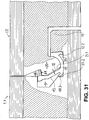
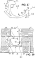
- FIG. 37 shown cross section Q10 describes a profile 2.10, in which the already in Fig. 23 represented foot 12.4 is present. Otherwise profile 2.10 will have the same parts as profile 2.9 (cf. Fig. 34 ) and is denoted by the same reference numerals.
- the head piece 5.3 also has the slightly upwardly inclined, lower pressure surface 65, which in the inserted state (see. Fig. 38 ) is adapted to the inner surface 59 of the locking element 20 and contacted with this.
- the inner surface 59 of the locking element 20 at the same time forms a groove flank of the recess 37.
- the recess 37 tapers slightly downward.
- the two inner surfaces 54, 59 contacting one another are arranged at an acute angle ⁇ 1 with respect to the useful surface 6. If one draws a perpendicular T to the effective area 6, said inner surfaces 54, 59 are at an acute, complementary angle ⁇ 3 with respect to the vertical T, the sum of both angles ⁇ 1 , ⁇ 3 being 180 °.
- the lower pressure surface 65 of the rounded head piece 5.3 is inclined at the aforementioned acute angle ⁇ with respect to the base surface 26.
- Figures 39 and 40 the profile 2.10 is shown in two perspective views. The figures show that the head piece 5.3 also has the rectilinear inner edge 75 without insertion edges.
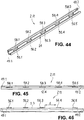
- Fig. 41 is a cross-section Q11 another, denoted by 2.11 profile shown.
- the profile 2.11 is in more Figures 43 and 44 in perspective views and in Figures 45, 46 shown in plan view of the interior of the profile and on the top of the head piece 5.3.
- the inner surface 4 of the wall 3 and the rounded lower surface of the locking element 20 are teilelliptisch.
- An essential feature of the profile 2.11 are outwardly projecting, elastically deformable, rectangular tongues 56.1, 56.2, 56.3, 56.4, 56.5, which consist of a transition region 47 (cf. Fig. 42 ) of the base part 42 to the movable leg 43, starting obliquely opposite the undeformed leg 43.
- the tongues 56.1, 56.2, 56.3, 56.4, 56.5 are manufactured in a piece of material with profile 2.11 by injection molding.
- the protruding tongues 56.1, 56.2, 56.3, 56.4, 56.5 each form a window 58.1, 58.2, 58.3, 58.4, 58.5 in the material of the wall 3.
- the profile 2.11 is provided with two insertion edges 49.1, 49.2.
- the execution of profile 2.11 according to Fig. 43 does not provide any introductory edges.
- the protruding tongues 56.1, 56.2, 56.3, 56.4, 56.5 are at the same inner distance d (cf. FIGURE 43 and 46 ) are arranged from each other along the profile.
- profile 2.11 is in Fig. 42 shown.
- the locking element 20 presses against the base part 42 of the profile, wherein the head piece 5.3 engages in the trapezoidal groove 52 and the leg 43 is in contact with the pressing surface 21.2.
- the contacting inner surfaces 54; 59 form with the effective area 6 of the building panels in Fig. 42 shown acute angle ⁇ . 1
- the recess 37 tapers slightly downwards.
- the spring-elastic tongues 56.1, 56.2, 56.3, 56.4, 56.5 deform and are braced against the oblique groove flank 23 of the first groove 9.
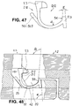
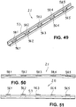
- Fig. 47 Of the Fig. 47 is a cross section Q12 of another, provided with tongues 56.1, 56.2, 56.3, 56.4, 56.5 profile to take 2.12.
- the difference to in Fig. 41 shown profile 2.11 is that his foot 12.3 similar to the profile 2.9 (see. Fig. 34 ), tapers upwards in its upper area.
- the inner surface 4 of the wall 3 of the profile 2.12 and the rounded lower surface of the locking element 20 are partially elliptical.
- Fig. 49 is the profile 2.12 in a perspective view towards the inside of the profile and in Figures 50, 51 shown in plan view of the interior of the profile and on the top of the head piece 5.3.
- the figures show that the head piece 5.3 has the rectilinear inner edge 75 without insertion edges.
- the used profile 2.12 is in Fig. 48 shown.
- the inner surface 54 of the foot 12.3 forms the obtuse angle ⁇ 2 with the inner surface 59 of the locking element 20.
- the resilient tongues 56.1, 56.2, 56.3, 56.4, 56.5 are based on the inclined groove flank 23 of the first groove 9 in a taut manner.
- Fig. 52 is a further cross-section (reference Q13) of a designated 2.13 profile shown in the Fig. 37 cross section Q10 (profile 2.10) is very similar.
- the profile 2.13 has a rounded head piece 5.4, the lower pressure surface 65 is arranged at an angle to the flat surface portion 63 on the inside of the leg 43.
- the inserted state cf. Fig. 53
- the mutually contacting inner surfaces 54; 59 with the effective area 6 of the building panel the already shown acute angle ⁇ . 1
- Another arrangement, for example, with obtuse angle ⁇ 2 of the contacting inner surfaces 54; 59 is possible.
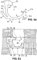
- the Fig. 54 shows a cross section Q14 of a designated 2.14 profile whose details differ from the profile 2.10 (see. Fig. 37 ).
- the difference between the two profiles is that the profile 2.14, in contrast to the profile 2.10 has a head 5.5 with a downward in the direction of the foot 12.4 inclined pressure surface 65.
- the pressure surface 65 In the inserted state of the connector (see. Fig. 55 ) forms the pressure surface 65 with the useful or base surface 6, 26 of the building panels a sharp angle ⁇ .
- the size of the angle ⁇ is about the size of the in Fig. 38 imaged angle ⁇ . Accordingly, the angle ⁇ in the present case about 3 ° to 5 ° and of course may vary. However, the angle ⁇ should be at least 2 ° in terms of advantageous self-locking of the two surfaces in contact.
- the inner surface 4 and the outer surface 28 of the wall 3 extends from the foot 12.4 beginning to the transition 47 to the movable leg 43 teilellipston.
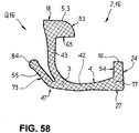
- FIG. 58 and 62 a further connector (reference number 2.16) is shown whose cross-section Q16 is approximately a combination of the cross-section Q2 (see FIG. Fig. 10 ) and the cross section Q9 (cf. Fig. 34 ).
- the connector has 2.16 already described head piece 5.3 with a slightly inclined pressure surface 65, the protruding web 55 and a web-shaped upwardly facing foot 77, whose lower, bounded by the footing 27 part similar to the foot 30 according to Fig. 10 is executed without bottom gradation.
- the base 27 is flat and merges into the slightly rounded lower outer surface 28 of the wall 3.
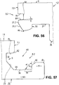
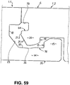
- the adapted to the connector 2.16 side surfaces 8.1, 82 of the building panels 1.1, 1.2 are detailed in FIGS. 56 and 57 as in Fig. 59 shown.
- the chunky locking element 20 of the building panel 1.2 is by the lower, inclined pressure surface 21.1, the lateral, perpendicular to the effective surface 6 extending pressure surface 21.2, the downwardly rounded surface 46 and the pressing surfaces 21.1, 21.2 facing away from inner surface 59 and by the support surface 64 of the groove 52 limited.
- the inner surface 59 is arranged perpendicular to the effective surface 6, but it may also be slightly inclined.
- an upper, inner bevel 80 and a further, smaller outer bevel 81 can be seen on the lip 15 of the building panel 1.1. Furthermore, the upper groove flank 13 of the groove 9 connects via a chamfer 82 to the abutment surface 7.1 of the building panel 1.1.
- the chamfers 80, 82 facilitate the placement of the connector 2.16 in the seat 60, especially when the connectors are to be pressed in using an unillustrated machine.
- the inner surface 17 of the lip 15 is arranged perpendicular to the base surface 26 of the building panel 1.1, so that a right angle ⁇ between the inner surface 17 and a planar surface portion 78 of the bottom 35 results. In the inserted state of the connector 2.16 (see. Fig.
- the connector is also 2.16 secure in the seat 60 of the building panel 1.1 housed while leaving the required mobility of the head piece 5.3 supporting leg 43rd
Landscapes
- Engineering & Computer Science (AREA)
- Architecture (AREA)
- Civil Engineering (AREA)
- Structural Engineering (AREA)
- Finishing Walls (AREA)
- Floor Finish (AREA)
- Joining Of Building Structures In Genera (AREA)
Priority Applications (3)
| Application Number | Priority Date | Filing Date | Title |
|---|---|---|---|
| EP12005281.6A EP2687650B1 (de) | 2012-07-19 | 2012-07-19 | Baupaneel mit einer Einrichtung zur Verbindung mit wenigstens einem weiteren Baupaneel auf einem Untergrund |
| PL12005281T PL2687650T3 (pl) | 2012-07-19 | 2012-07-19 | Panel konstrukcyjny z układem do łączenia z co najmniej jednym innym panelem konstrukcyjnym na podłożu |
| EA201300728A EA027837B1 (ru) | 2012-07-19 | 2013-07-18 | Строительная панель с приспособлением для соединения по меньшей мере с одной последующей строительной панелью на основании |
Applications Claiming Priority (1)
| Application Number | Priority Date | Filing Date | Title |
|---|---|---|---|
| EP12005281.6A EP2687650B1 (de) | 2012-07-19 | 2012-07-19 | Baupaneel mit einer Einrichtung zur Verbindung mit wenigstens einem weiteren Baupaneel auf einem Untergrund |
Publications (2)
| Publication Number | Publication Date |
|---|---|
| EP2687650A1 EP2687650A1 (de) | 2014-01-22 |
| EP2687650B1 true EP2687650B1 (de) | 2017-12-13 |
Family
ID=46724190
Family Applications (1)
| Application Number | Title | Priority Date | Filing Date |
|---|---|---|---|
| EP12005281.6A Active EP2687650B1 (de) | 2012-07-19 | 2012-07-19 | Baupaneel mit einer Einrichtung zur Verbindung mit wenigstens einem weiteren Baupaneel auf einem Untergrund |
Country Status (3)
| Country | Link |
|---|---|
| EP (1) | EP2687650B1 (pl) |
| EA (1) | EA027837B1 (pl) |
| PL (1) | PL2687650T3 (pl) |
Cited By (1)
| Publication number | Priority date | Publication date | Assignee | Title |
|---|---|---|---|---|
| RU2730138C2 (ru) * | 2015-10-08 | 2020-08-19 | Берриаллок Нв | Набор панелей для покрытия полов, стен или потолков |
Families Citing this family (2)
| Publication number | Priority date | Publication date | Assignee | Title |
|---|---|---|---|---|
| EP3309322A1 (de) * | 2016-10-11 | 2018-04-18 | Franz Eschlbeck | Paneel und mechanische paneelverbindung |
| CN106836725A (zh) * | 2016-12-20 | 2017-06-13 | 苏州金威特工具有限公司 | 一种金属包边的实木地热地板锁扣 |
Family Cites Families (6)
| Publication number | Priority date | Publication date | Assignee | Title |
|---|---|---|---|---|
| DE10237397A1 (de) | 2002-08-09 | 2004-02-19 | Profilex Ag | Vorrichtung zum Verbinden von zwei plattenförmigen Paneelen |
| SE531111C2 (sv) | 2006-12-08 | 2008-12-23 | Vaelinge Innovation Ab | Mekanisk låsning av golvpaneler |
| BE1018627A5 (nl) | 2009-01-16 | 2011-05-03 | Flooring Ind Ltd Sarl | Vloerpaneel. |
| DE102010004717A1 (de) * | 2010-01-15 | 2011-07-21 | Pergo (Europe) Ab | Set aus Paneelen umfassend Halteprofile mit einem separaten Clip sowie Verfahren zum Einbringen des Clips |
| EP2415944B1 (de) * | 2010-08-06 | 2013-02-13 | Barlinek S.A. | Fußbodenpaneel mit einer Verbindungseinrichtung |
| DE202011108752U1 (de) * | 2011-12-06 | 2012-01-24 | Akzenta Paneele + Profile Gmbh | Verriegelungssystem für Paneelen und Paneel mit Verriegelungssystem |
-
2012
- 2012-07-19 PL PL12005281T patent/PL2687650T3/pl unknown
- 2012-07-19 EP EP12005281.6A patent/EP2687650B1/de active Active
-
2013
- 2013-07-18 EA EA201300728A patent/EA027837B1/ru unknown
Non-Patent Citations (1)
| Title |
|---|
| None * |
Cited By (1)
| Publication number | Priority date | Publication date | Assignee | Title |
|---|---|---|---|---|
| RU2730138C2 (ru) * | 2015-10-08 | 2020-08-19 | Берриаллок Нв | Набор панелей для покрытия полов, стен или потолков |
Also Published As
| Publication number | Publication date |
|---|---|
| EP2687650A1 (de) | 2014-01-22 |
| EA201300728A3 (ru) | 2014-04-30 |
| PL2687650T3 (pl) | 2018-06-29 |
| EA201300728A2 (ru) | 2014-01-30 |
| EA027837B1 (ru) | 2017-09-29 |
Similar Documents
| Publication | Publication Date | Title |
|---|---|---|
| EP2520737B1 (de) | Baupaneel mit einer Einrichtung zur Verbindung mit wenigstens einem weiteren Baupaneel auf einem Untergrund | |
| DE102007032885B4 (de) | Paneel, insbesondere Bodenpaneel und Einrichtung zum Verriegeln miteinander verbundener Paneele | |
| DE102007017087B4 (de) | Paneel, insbesondere Bodenpaneel | |
| EP2270291B1 (de) | Satz aus Bauplatten mit einer Einrichtung zum Verriegeln zweier dieser Bauplatten | |
| EP1527240B1 (de) | Verfahren zur Herstellung von miteinander verbindbaren Bauteilen sowie Anordnung von Bauteilen mit Verbindungselementen | |
| EP1420125B1 (de) | Einrichtung bestehend aus zwei miteinander verbindbaren Bauplatten und einem Einsatz zum Verriegeln dieser Bauplatten | |
| EP3321448B1 (de) | Paneel | |
| EP1380710B1 (de) | Fussbodenpaneel und Verfahren zum Verlegen eines Fussbodens | |
| EP1367194B1 (de) | Fussbodenpaneel und Verfahren zum Verlegen eines solchen Paneels | |
| EP1165906A1 (de) | Paneel sowie befestigungssystem für paneele | |
| EP3117055B1 (de) | Belag aus mechanisch miteinander verbindbaren paneelen | |
| DE202007012734U1 (de) | Profilleiste, insbesondere Sockelleiste | |
| EP2687650B1 (de) | Baupaneel mit einer Einrichtung zur Verbindung mit wenigstens einem weiteren Baupaneel auf einem Untergrund | |
| EP3464751A1 (de) | Elemente zur bildung von flächen und deren verbindungen | |
| EP2415944B1 (de) | Fußbodenpaneel mit einer Verbindungseinrichtung | |
| DE202009005090U1 (de) | Anordnung zur Befestigung von Modulen einer Photovoltaik-Einrichtung oder von Solarpaneelen | |
| DE202012102709U1 (de) | Baupaneel mit einer Einrichtung zur Verbindung mit wenigstens einem weiteren Baupaneel auf einem Untergrund | |
| EP2899324B1 (de) | Entwässerungsrinne mit dichtem Stoßbereich | |
| EP2995747B1 (de) | Mechanische verbindung für paneele und verfahren zur montage einer verriegelungsfeder in einem paneel | |
| EP3271527B1 (de) | Mechanische verbindung für paneele und verfahren zur herstellung von verbindungsmitteln | |
| DE102015102671B4 (de) | Paneele mit einer mechanischen Verbindung für diese Paneele, Verfahren zur Montage einer Verriegelungsfeder in einem Paneel und Verfahren zum Verbinden von Paneelen mit einer mechanischen Verbindung | |
| EP2995746B1 (de) | Mechanische verbindung für paneele und verfahren zur montage einer verriegelungsfeder in einem paneel | |
| DE202011003046U1 (de) | Verbindungselement zur Verbindung von flächigen Bauteilen | |
| DE202011100195U1 (de) | Baupaneel mit einer Einrichtung zur Verbindung mit wenigstens einem weiteren Baupaneel auf einem Untergrund | |
| DE20119830U1 (de) | Anordnung von Bauteilen |
Legal Events
| Date | Code | Title | Description |
|---|---|---|---|
| PUAI | Public reference made under article 153(3) epc to a published international application that has entered the european phase |
Free format text: ORIGINAL CODE: 0009012 |
|
| AK | Designated contracting states |
Kind code of ref document: A1 Designated state(s): AL AT BE BG CH CY CZ DE DK EE ES FI FR GB GR HR HU IE IS IT LI LT LU LV MC MK MT NL NO PL PT RO RS SE SI SK SM TR |
|
| AX | Request for extension of the european patent |
Extension state: BA ME |
|
| 17P | Request for examination filed |
Effective date: 20140328 |
|
| RBV | Designated contracting states (corrected) |
Designated state(s): AL AT BE BG CH CY CZ DE DK EE ES FI FR GB GR HR HU IE IS IT LI LT LU LV MC MK MT NL NO PL PT RO RS SE SI SK SM TR |
|
| 17Q | First examination report despatched |
Effective date: 20160817 |
|
| GRAP | Despatch of communication of intention to grant a patent |
Free format text: ORIGINAL CODE: EPIDOSNIGR1 |
|
| INTG | Intention to grant announced |
Effective date: 20170707 |
|
| GRAS | Grant fee paid |
Free format text: ORIGINAL CODE: EPIDOSNIGR3 |
|
| GRAA | (expected) grant |
Free format text: ORIGINAL CODE: 0009210 |
|
| AK | Designated contracting states |
Kind code of ref document: B1 Designated state(s): AL AT BE BG CH CY CZ DE DK EE ES FI FR GB GR HR HU IE IS IT LI LT LU LV MC MK MT NL NO PL PT RO RS SE SI SK SM TR |
|
| REG | Reference to a national code |
Ref country code: GB Ref legal event code: FG4D Free format text: NOT ENGLISH |
|
| REG | Reference to a national code |
Ref country code: AT Ref legal event code: REF Ref document number: 954516 Country of ref document: AT Kind code of ref document: T Effective date: 20171215 Ref country code: CH Ref legal event code: EP |
|
| REG | Reference to a national code |
Ref country code: IE Ref legal event code: FG4D Free format text: LANGUAGE OF EP DOCUMENT: GERMAN |
|
| REG | Reference to a national code |
Ref country code: DE Ref legal event code: R096 Ref document number: 502012011798 Country of ref document: DE |
|
| REG | Reference to a national code |
Ref country code: RO Ref legal event code: EPE |
|
| REG | Reference to a national code |
Ref country code: SE Ref legal event code: TRGR |
|
| REG | Reference to a national code |
Ref country code: NL Ref legal event code: MP Effective date: 20171213 |
|
| REG | Reference to a national code |
Ref country code: LT Ref legal event code: MG4D |
|
| PG25 | Lapsed in a contracting state [announced via postgrant information from national office to epo] |
Ref country code: FI Free format text: LAPSE BECAUSE OF FAILURE TO SUBMIT A TRANSLATION OF THE DESCRIPTION OR TO PAY THE FEE WITHIN THE PRESCRIBED TIME-LIMIT Effective date: 20171213 Ref country code: LT Free format text: LAPSE BECAUSE OF FAILURE TO SUBMIT A TRANSLATION OF THE DESCRIPTION OR TO PAY THE FEE WITHIN THE PRESCRIBED TIME-LIMIT Effective date: 20171213 Ref country code: NO Free format text: LAPSE BECAUSE OF FAILURE TO SUBMIT A TRANSLATION OF THE DESCRIPTION OR TO PAY THE FEE WITHIN THE PRESCRIBED TIME-LIMIT Effective date: 20180313 |
|
| PG25 | Lapsed in a contracting state [announced via postgrant information from national office to epo] |
Ref country code: HR Free format text: LAPSE BECAUSE OF FAILURE TO SUBMIT A TRANSLATION OF THE DESCRIPTION OR TO PAY THE FEE WITHIN THE PRESCRIBED TIME-LIMIT Effective date: 20171213 Ref country code: BG Free format text: LAPSE BECAUSE OF FAILURE TO SUBMIT A TRANSLATION OF THE DESCRIPTION OR TO PAY THE FEE WITHIN THE PRESCRIBED TIME-LIMIT Effective date: 20180313 Ref country code: RS Free format text: LAPSE BECAUSE OF FAILURE TO SUBMIT A TRANSLATION OF THE DESCRIPTION OR TO PAY THE FEE WITHIN THE PRESCRIBED TIME-LIMIT Effective date: 20171213 Ref country code: GR Free format text: LAPSE BECAUSE OF FAILURE TO SUBMIT A TRANSLATION OF THE DESCRIPTION OR TO PAY THE FEE WITHIN THE PRESCRIBED TIME-LIMIT Effective date: 20180314 Ref country code: LV Free format text: LAPSE BECAUSE OF FAILURE TO SUBMIT A TRANSLATION OF THE DESCRIPTION OR TO PAY THE FEE WITHIN THE PRESCRIBED TIME-LIMIT Effective date: 20171213 |
|
| PG25 | Lapsed in a contracting state [announced via postgrant information from national office to epo] |
Ref country code: NL Free format text: LAPSE BECAUSE OF FAILURE TO SUBMIT A TRANSLATION OF THE DESCRIPTION OR TO PAY THE FEE WITHIN THE PRESCRIBED TIME-LIMIT Effective date: 20171213 |
|
| REG | Reference to a national code |
Ref country code: FR Ref legal event code: PLFP Year of fee payment: 7 |
|
| PG25 | Lapsed in a contracting state [announced via postgrant information from national office to epo] |
Ref country code: SK Free format text: LAPSE BECAUSE OF FAILURE TO SUBMIT A TRANSLATION OF THE DESCRIPTION OR TO PAY THE FEE WITHIN THE PRESCRIBED TIME-LIMIT Effective date: 20171213 Ref country code: CZ Free format text: LAPSE BECAUSE OF FAILURE TO SUBMIT A TRANSLATION OF THE DESCRIPTION OR TO PAY THE FEE WITHIN THE PRESCRIBED TIME-LIMIT Effective date: 20171213 Ref country code: ES Free format text: LAPSE BECAUSE OF FAILURE TO SUBMIT A TRANSLATION OF THE DESCRIPTION OR TO PAY THE FEE WITHIN THE PRESCRIBED TIME-LIMIT Effective date: 20171213 Ref country code: CY Free format text: LAPSE BECAUSE OF FAILURE TO SUBMIT A TRANSLATION OF THE DESCRIPTION OR TO PAY THE FEE WITHIN THE PRESCRIBED TIME-LIMIT Effective date: 20171213 Ref country code: EE Free format text: LAPSE BECAUSE OF FAILURE TO SUBMIT A TRANSLATION OF THE DESCRIPTION OR TO PAY THE FEE WITHIN THE PRESCRIBED TIME-LIMIT Effective date: 20171213 |
|
| PG25 | Lapsed in a contracting state [announced via postgrant information from national office to epo] |
Ref country code: SM Free format text: LAPSE BECAUSE OF FAILURE TO SUBMIT A TRANSLATION OF THE DESCRIPTION OR TO PAY THE FEE WITHIN THE PRESCRIBED TIME-LIMIT Effective date: 20171213 Ref country code: IS Free format text: LAPSE BECAUSE OF FAILURE TO SUBMIT A TRANSLATION OF THE DESCRIPTION OR TO PAY THE FEE WITHIN THE PRESCRIBED TIME-LIMIT Effective date: 20180413 Ref country code: IT Free format text: LAPSE BECAUSE OF FAILURE TO SUBMIT A TRANSLATION OF THE DESCRIPTION OR TO PAY THE FEE WITHIN THE PRESCRIBED TIME-LIMIT Effective date: 20171213 |
|
| REG | Reference to a national code |
Ref country code: DE Ref legal event code: R097 Ref document number: 502012011798 Country of ref document: DE |
|
| PG25 | Lapsed in a contracting state [announced via postgrant information from national office to epo] |
Ref country code: MT Free format text: LAPSE BECAUSE OF FAILURE TO SUBMIT A TRANSLATION OF THE DESCRIPTION OR TO PAY THE FEE WITHIN THE PRESCRIBED TIME-LIMIT Effective date: 20171213 |
|
| PLBE | No opposition filed within time limit |
Free format text: ORIGINAL CODE: 0009261 |
|
| STAA | Information on the status of an ep patent application or granted ep patent |
Free format text: STATUS: NO OPPOSITION FILED WITHIN TIME LIMIT |
|
| 26N | No opposition filed |
Effective date: 20180914 |
|
| PG25 | Lapsed in a contracting state [announced via postgrant information from national office to epo] |
Ref country code: DK Free format text: LAPSE BECAUSE OF FAILURE TO SUBMIT A TRANSLATION OF THE DESCRIPTION OR TO PAY THE FEE WITHIN THE PRESCRIBED TIME-LIMIT Effective date: 20171213 |
|
| PG25 | Lapsed in a contracting state [announced via postgrant information from national office to epo] |
Ref country code: SI Free format text: LAPSE BECAUSE OF FAILURE TO SUBMIT A TRANSLATION OF THE DESCRIPTION OR TO PAY THE FEE WITHIN THE PRESCRIBED TIME-LIMIT Effective date: 20171213 |
|
| REG | Reference to a national code |
Ref country code: CH Ref legal event code: PL |
|
| PG25 | Lapsed in a contracting state [announced via postgrant information from national office to epo] |
Ref country code: MC Free format text: LAPSE BECAUSE OF FAILURE TO SUBMIT A TRANSLATION OF THE DESCRIPTION OR TO PAY THE FEE WITHIN THE PRESCRIBED TIME-LIMIT Effective date: 20171213 Ref country code: LU Free format text: LAPSE BECAUSE OF NON-PAYMENT OF DUE FEES Effective date: 20180719 |
|
| REG | Reference to a national code |
Ref country code: BE Ref legal event code: MM Effective date: 20180731 |
|
| REG | Reference to a national code |
Ref country code: IE Ref legal event code: MM4A |
|
| PG25 | Lapsed in a contracting state [announced via postgrant information from national office to epo] |
Ref country code: IE Free format text: LAPSE BECAUSE OF NON-PAYMENT OF DUE FEES Effective date: 20180719 Ref country code: CH Free format text: LAPSE BECAUSE OF NON-PAYMENT OF DUE FEES Effective date: 20180731 Ref country code: LI Free format text: LAPSE BECAUSE OF NON-PAYMENT OF DUE FEES Effective date: 20180731 |
|
| PG25 | Lapsed in a contracting state [announced via postgrant information from national office to epo] |
Ref country code: BE Free format text: LAPSE BECAUSE OF NON-PAYMENT OF DUE FEES Effective date: 20180731 |
|
| REG | Reference to a national code |
Ref country code: AT Ref legal event code: MM01 Ref document number: 954516 Country of ref document: AT Kind code of ref document: T Effective date: 20180719 |
|
| PG25 | Lapsed in a contracting state [announced via postgrant information from national office to epo] |
Ref country code: AT Free format text: LAPSE BECAUSE OF NON-PAYMENT OF DUE FEES Effective date: 20180719 |
|
| PG25 | Lapsed in a contracting state [announced via postgrant information from national office to epo] |
Ref country code: TR Free format text: LAPSE BECAUSE OF FAILURE TO SUBMIT A TRANSLATION OF THE DESCRIPTION OR TO PAY THE FEE WITHIN THE PRESCRIBED TIME-LIMIT Effective date: 20171213 |
|
| PG25 | Lapsed in a contracting state [announced via postgrant information from national office to epo] |
Ref country code: PT Free format text: LAPSE BECAUSE OF FAILURE TO SUBMIT A TRANSLATION OF THE DESCRIPTION OR TO PAY THE FEE WITHIN THE PRESCRIBED TIME-LIMIT Effective date: 20171213 Ref country code: HU Free format text: LAPSE BECAUSE OF FAILURE TO SUBMIT A TRANSLATION OF THE DESCRIPTION OR TO PAY THE FEE WITHIN THE PRESCRIBED TIME-LIMIT; INVALID AB INITIO Effective date: 20120719 |
|
| PG25 | Lapsed in a contracting state [announced via postgrant information from national office to epo] |
Ref country code: MK Free format text: LAPSE BECAUSE OF NON-PAYMENT OF DUE FEES Effective date: 20171213 |
|
| PG25 | Lapsed in a contracting state [announced via postgrant information from national office to epo] |
Ref country code: AL Free format text: LAPSE BECAUSE OF FAILURE TO SUBMIT A TRANSLATION OF THE DESCRIPTION OR TO PAY THE FEE WITHIN THE PRESCRIBED TIME-LIMIT Effective date: 20171213 |
|
| PGFP | Annual fee paid to national office [announced via postgrant information from national office to epo] |
Ref country code: PL Payment date: 20250618 Year of fee payment: 14 |
|
| PGFP | Annual fee paid to national office [announced via postgrant information from national office to epo] |
Ref country code: DE Payment date: 20250722 Year of fee payment: 14 |
|
| PGFP | Annual fee paid to national office [announced via postgrant information from national office to epo] |
Ref country code: GB Payment date: 20250722 Year of fee payment: 14 |
|
| PGFP | Annual fee paid to national office [announced via postgrant information from national office to epo] |
Ref country code: FR Payment date: 20250725 Year of fee payment: 14 |
|
| PGFP | Annual fee paid to national office [announced via postgrant information from national office to epo] |
Ref country code: SE Payment date: 20250722 Year of fee payment: 14 |
|
| PGFP | Annual fee paid to national office [announced via postgrant information from national office to epo] |
Ref country code: RO Payment date: 20250716 Year of fee payment: 14 |