EP2687650A1 - Baupaneel mit einer Einrichtung zur Verbindung mit wenigstens einem weiteren Baupaneel auf einem Untergrund - Google Patents
Baupaneel mit einer Einrichtung zur Verbindung mit wenigstens einem weiteren Baupaneel auf einem Untergrund Download PDFInfo
- Publication number
- EP2687650A1 EP2687650A1 EP12005281.6A EP12005281A EP2687650A1 EP 2687650 A1 EP2687650 A1 EP 2687650A1 EP 12005281 A EP12005281 A EP 12005281A EP 2687650 A1 EP2687650 A1 EP 2687650A1
- Authority
- EP
- European Patent Office
- Prior art keywords
- connector
- building panel
- groove
- panel according
- foot
- Prior art date
- Legal status (The legal status is an assumption and is not a legal conclusion. Google has not performed a legal analysis and makes no representation as to the accuracy of the status listed.)
- Granted
Links
- 238000010276 construction Methods 0.000 title claims description 4
- 230000007704 transition Effects 0.000 claims description 20
- 230000001154 acute effect Effects 0.000 claims description 13
- 239000000463 material Substances 0.000 claims description 8
- 238000003780 insertion Methods 0.000 claims description 6
- 230000037431 insertion Effects 0.000 claims description 6
- 239000000758 substrate Substances 0.000 claims description 6
- 239000002689 soil Substances 0.000 claims description 3
- 230000013011 mating Effects 0.000 abstract 1
- 210000002414 leg Anatomy 0.000 description 35
- 210000002105 tongue Anatomy 0.000 description 15
- 239000010410 layer Substances 0.000 description 11
- 239000007787 solid Substances 0.000 description 8
- 239000004033 plastic Substances 0.000 description 6
- 229920003023 plastic Polymers 0.000 description 6
- -1 polyethylene Polymers 0.000 description 5
- 239000004952 Polyamide Substances 0.000 description 4
- 229920002647 polyamide Polymers 0.000 description 4
- 239000004417 polycarbonate Substances 0.000 description 4
- 229920000515 polycarbonate Polymers 0.000 description 4
- 229920000139 polyethylene terephthalate Polymers 0.000 description 4
- 239000005020 polyethylene terephthalate Substances 0.000 description 4
- 239000002023 wood Substances 0.000 description 4
- 239000011324 bead Substances 0.000 description 3
- 241001295925 Gegenes Species 0.000 description 2
- 229930040373 Paraformaldehyde Natural products 0.000 description 2
- 239000004698 Polyethylene Substances 0.000 description 2
- 239000004743 Polypropylene Substances 0.000 description 2
- 239000012792 core layer Substances 0.000 description 2
- 239000002184 metal Substances 0.000 description 2
- 229920003229 poly(methyl methacrylate) Polymers 0.000 description 2
- 229920000573 polyethylene Polymers 0.000 description 2
- 239000004926 polymethyl methacrylate Substances 0.000 description 2
- 229920006324 polyoxymethylene Polymers 0.000 description 2
- 229920001155 polypropylene Polymers 0.000 description 2
- 229920002635 polyurethane Polymers 0.000 description 2
- 239000004814 polyurethane Substances 0.000 description 2
- 239000000243 solution Substances 0.000 description 2
- 239000004793 Polystyrene Substances 0.000 description 1
- PPBRXRYQALVLMV-UHFFFAOYSA-N Styrene Natural products C=CC1=CC=CC=C1 PPBRXRYQALVLMV-UHFFFAOYSA-N 0.000 description 1
- 239000004809 Teflon Substances 0.000 description 1
- 229920006362 Teflon® Polymers 0.000 description 1
- 230000004308 accommodation Effects 0.000 description 1
- 230000000844 anti-bacterial effect Effects 0.000 description 1
- 238000005253 cladding Methods 0.000 description 1
- 230000000295 complement effect Effects 0.000 description 1
- 239000002131 composite material Substances 0.000 description 1
- 150000001875 compounds Chemical class 0.000 description 1
- 229920001577 copolymer Polymers 0.000 description 1
- 239000007799 cork Substances 0.000 description 1
- 230000008878 coupling Effects 0.000 description 1
- 238000010168 coupling process Methods 0.000 description 1
- 238000005859 coupling reaction Methods 0.000 description 1
- 229920006351 engineering plastic Polymers 0.000 description 1
- 210000003414 extremity Anatomy 0.000 description 1
- 239000003063 flame retardant Substances 0.000 description 1
- 229920002313 fluoropolymer Polymers 0.000 description 1
- 238000001746 injection moulding Methods 0.000 description 1
- 238000009434 installation Methods 0.000 description 1
- 238000007639 printing Methods 0.000 description 1
- 239000002994 raw material Substances 0.000 description 1
- 230000002787 reinforcement Effects 0.000 description 1
- 239000011435 rock Substances 0.000 description 1
- 238000007789 sealing Methods 0.000 description 1
- 238000000926 separation method Methods 0.000 description 1
- 230000000087 stabilizing effect Effects 0.000 description 1
- 229920003002 synthetic resin Polymers 0.000 description 1
- 239000000057 synthetic resin Substances 0.000 description 1
- 229920001169 thermoplastic Polymers 0.000 description 1
- 239000004416 thermosoftening plastic Substances 0.000 description 1
- 210000000689 upper leg Anatomy 0.000 description 1
- 208000008918 voyeurism Diseases 0.000 description 1
Images


Classifications
-
- E—FIXED CONSTRUCTIONS
- E04—BUILDING
- E04F—FINISHING WORK ON BUILDINGS, e.g. STAIRS, FLOORS
- E04F15/00—Flooring
- E04F15/02—Flooring or floor layers composed of a number of similar elements
- E04F15/02038—Flooring or floor layers composed of a number of similar elements characterised by tongue and groove connections between neighbouring flooring elements
-
- E—FIXED CONSTRUCTIONS
- E04—BUILDING
- E04F—FINISHING WORK ON BUILDINGS, e.g. STAIRS, FLOORS
- E04F2201/00—Joining sheets or plates or panels
- E04F2201/01—Joining sheets, plates or panels with edges in abutting relationship
- E04F2201/0138—Joining sheets, plates or panels with edges in abutting relationship by moving the sheets, plates or panels perpendicular to the main plane
- E04F2201/0146—Joining sheets, plates or panels with edges in abutting relationship by moving the sheets, plates or panels perpendicular to the main plane with snap action of the edge connectors
-
- E—FIXED CONSTRUCTIONS
- E04—BUILDING
- E04F—FINISHING WORK ON BUILDINGS, e.g. STAIRS, FLOORS
- E04F2201/00—Joining sheets or plates or panels
- E04F2201/05—Separate connectors or inserts, e.g. pegs, pins, keys or strips
- E04F2201/0523—Separate tongues; Interlocking keys, e.g. joining mouldings of circular, square or rectangular shape
- E04F2201/0535—Separate tongues; Interlocking keys, e.g. joining mouldings of circular, square or rectangular shape adapted for snap locking
-
- E—FIXED CONSTRUCTIONS
- E04—BUILDING
- E04F—FINISHING WORK ON BUILDINGS, e.g. STAIRS, FLOORS
- E04F2201/00—Joining sheets or plates or panels
- E04F2201/05—Separate connectors or inserts, e.g. pegs, pins, keys or strips
- E04F2201/0523—Separate tongues; Interlocking keys, e.g. joining mouldings of circular, square or rectangular shape
- E04F2201/0564—Separate tongues; Interlocking keys, e.g. joining mouldings of circular, square or rectangular shape depending on the use of specific materials
- E04F2201/0588—Separate tongues; Interlocking keys, e.g. joining mouldings of circular, square or rectangular shape depending on the use of specific materials of organic plastics with or without reinforcements or filling materials
Definitions
- a building panel with such a facility is off WO 2008/004960 known.
- a semicircular recess of a previously laid building panel is an approximately boomerangförmiger, rocking-like connector used according to Figures 6a to 6d, which is moved by a Jacobpaneel under leverage until a thicker edge of the connector - seen in cross section of the panel connection - in one to the edge Compatible groove of the Gegenpaneels einspringt.
- the separate connector has the task to ensure the locking of the building panels substantially perpendicular to the tread.
- the task of horizontal locking takes over in a conventional manner, the locking arm with his lip.
- the known connector has an additional, directed to the Gegenpaneel own lip, but this provides only for a reinforcement of the existing horizontal locking.
- a disadvantage of the known device is that the connector can fall out of the attachment in the groove relatively easily before joining the two building panels, especially when the material of the connector is resilient. The stability of the compound seems to be insufficient.
- FIG. 5 To derive an anchor-like, consisting of two parts connector, in which a projecting over a side surface of a panel center web, called punch, engages in an inner space of a pressed into a groove of a second panel in C-shaped head.
- the profiled side surfaces of the two interconnected panels extend substantially obliquely to the tread surface of the panels, wherein the coupled parts of the connector are directed perpendicular to the side surfaces.
- Both parts of the connector are constructed mirror-symmetrically to its longitudinal axis.
- a disadvantage of a thus configured panel connection with two-piece connector according to Fig. 5 is that a subsequent separation of the interconnected floor panels is not feasible. Also, a connection of the floor panels together or their installation on a substrate seems problematic be, because mounting in the horizontal direction using the known block impact impossible and mounting with pivotal movement is particularly difficult.
- the object of the invention is to develop an alternative generic device for connecting polygonal, plate-shaped building panels together with the help of separate connectors that do not act like a rock and whose hold on the building panel is safe and stable.
- the building panel which is pivoted down against the already laid down, referred to as Gegenpaneel.
- the terms such as “top”, “top”, “bottom”, “bottom”, “below”, “above” etc. refer to the laid on a foundation building panels, as shown in the drawing.
- the separate connector is referred to as a profile.
- the device according to the invention is approximately to those which includes a so-called hook connection, in which normally the hook-joint forming parts: lip on the locking arm and directed to the ground locking element of the Gegenpaneels should be tightly hooked together and the abutting surfaces of the two building panels to be brought into surface contact with each other to secure the locking of the building panels in the horizontal direction.
- hook connection in which normally the hook-joint forming parts: lip on the locking arm and directed to the ground locking element of the Gegenpaneels should be tightly hooked together and the abutting surfaces of the two building panels to be brought into surface contact with each other to secure the locking of the building panels in the horizontal direction.
- the separate connector according to the invention is made of plastic.
- Plastics for the connector include thermoplastics such as polyethylene (PE), polypropylene (PP), polystyrene (PS), polyamides (PA), polycarbonates (PC), polyethylene terephthalate (PET), and the like.
- thermoplastics such as polyethylene (PE), polypropylene (PP), polystyrene (PS), polyamides (PA), polycarbonates (PC), polyethylene terephthalate (PET), and the like.
- engineering plastics such as styrene copolymers (ABS), polyamides (PA), polycarbonates (PC), polyethylene terephthalate (PET), polymethylmethacrylate (PMMA), polyoxymethylene (POM), fluoroplastics (Teflon), polyurethanes (PUR) in question.
- the foot of the profile may be web-shaped and / or solid, wherein it is of crucial importance that this has an inwardly inclined side surface which is at least partially in contact with the inner surface of the lip - in the inserted state.
- the angle of inclination of the side surface of the foot to its footprint may correspond to said sharp angle at the lip. If the inner surface of the lip is arranged at right angles to the bottom of the locking arm or to the base surface of the building panel, the foot can press with its lower part against said inner surface.
- the foot and the lower part of the mounted connector almost form-fitting, before and after the lowering of the Gegenpaneels rest on the locking arm.
- the connector may have at least one outwardly extending projection extending in the longitudinal direction of the connector in a transition region of its base part to the movable leg.
- the projection may be in the inserted state of the connector in contact with the groove flank of the second groove.
- the profile can also be made of so-called integral plastics.
- a profile may for example have a hard foot and a relatively soft, adjoining the head leg.
- the head piece and the foot can be made stiffer than the legal material of the profile.
- the profile can have smooth and / or roughened surfaces.
- the profile can be made of metal, wood material or composite.
- the profile may be elastically deformable at least in its leg region.
- the elasticity of the profile may be assisted by corresponding constrictions or gentle transitions of the leg to the foot.
- the head piece may have a strip-shaped, planar, in the inserted state of the first groove flank facing pressure surface, which in turn in a - in cross-section of the profile seen - downward, oblique or rounded sliding surface continues.
- the first, upper groove flank of the groove for receiving the profile runs parallel and the second, lower groove flank obliquely to the useful or base surface of the building panel, wherein the lower groove flank merges into the bottom of the locking arm.
- the two groove flanks close to a perpendicular to the effective surface arranged groove bottom of said groove. So configured groove has enough space for pivoting the head piece.
- the flat pressure surface of the head piece remains in the non-caused by the lowering counter panel, tensioned state in surface contact with the upper groove flank or presses against them.
- the bottom of the locking arm is preferably parallel to the base surface and then forms a support surface for the foot and for the lower part of the wall of the connector.
- a flat or stepped floor is suitable.
- the lower part of the inserted profile At the trough, so its base part can be supported.
- the einmont Arthur profile according to the invention therefore applies the principle of at least three contact surfaces of this profile with the lower building panel, namely with the inclined inner surface of the lip, with the bottom of the locking arm and with the upper groove flank of the first groove.
- This set profile sits securely on the side surface of the lower building panel and has little chance to solve independently.
- four contact surfaces of the profile with the lower building panel are provided, wherein the fourth contact surface is formed by a projecting from the profile, resilient web or at least one down, resilient tongue in the inserted state against the lower , oblique groove edge of the first groove presses.
- the head piece When the building panel is pivoted downwards in the direction of the floor of the already laid building panel, the head piece can exert a rotary movement about the recess or a gradation of the floor of the locking arm.
- the leg of the profile is pivoted.
- the foot of the connector can remain immobile in its position on the inner surface of the lip and the base part of the profile.
- the profiles can be pressed into the existing groove of the building panel manually or mechanically or with the aid of an automatic machine.
- the building panels provided with the profiles can be stored and distributed in this form.
- the profile is made of plastic, it can be cheaply made available as a mass-produced article.
- the profiles according to the invention are essentially intended for the narrow edges of the building panels. However, even in the longer side surfaces of the building panels may be integrated if they are adapted to the separate connector accordingly.
- the oblique pressing surface of the downward locking element is at an angle ⁇ 45 °, preferably 60 ° relative to the effective surface. This angular size ensures optimum sliding of the locking element on the head piece, without the head piece can fall out of the seat.
- the rounded surface of the locking element may transition into a recessed with respect to the upper abutment surface of the building panel slope, such that a sharp, approximately V-shaped transition for receiving the head piece is formed.
- the head piece can also engage in a groove of the structural element carrying the locking element.
- the groove is approximately rectangular or trapezoidal.
- the rounded surface of the locking element passes over an obliquely or perpendicularly arranged with respect to the usable surface, flat surface in the downwardly open recess of the locking element supporting the building panel.
- a strip-shaped inner surface of the upper part of the foot can be provided, which is compatible with the said flat surface.
- the building panels can be made of plastic, metal, wood-based material, paper or other renewable raw materials, such as cork.
- the building panels can be made in solid or layered construction, such as known HDF or MDF panels, and have a wood or tile decor, which with at least one layer of a transparent or translucent synthetic resin is covered.
- the building panels may be equipped with antibacterial and / or fire retardants.
- the building panels can be used as floor panels, as wall cladding panels or as furniture parts.
- FIGS. 1, 2 and 16 show two building panels 1.1, 1.2 before and after the pivoting down of the building panel 1.2 (Gegenpaneel) in the direction of the substrate 11, to which the building panel 1.1 is already laid. Characteristic of the figures is the lack of a separate connector, which will be described in detail below.
- the two building panels 1.1, 1.2 each consist of a wear layer 39, a bottom layer 40 and an intermediate core layer 38 of wood material.
- the wear layer 39 is provided with a decorative layer 41, the surface of which forms a step or useful surface 6.
- the bottom layer 40 in turn has a base surface 11 facing the base surface 26.
- the building panel 1.1 is characterized by a profiled, through the utility and base surfaces 6; 26 limited side surface 8.1, comprising an abutment surface 7.1, a recessed relative to the abutment surface, the first groove 9 and a projecting beyond the abutment surface 7.1 locking arm 14 with an upwardly projecting lip 15th
- the first groove 9 is polygonal in cross section and has a relation to the impact surface 7.1 recessed groove bottom 10 which is arranged parallel to the impact surface 7.1 and in an upper, plane parallel to the effective surface 6 extending groove flank 13 and an obliquely directed lower groove flank 23 expires.
- the latter again goes into a parallel to the base surface 26 lying bottom 35 of the locking arm 14, wherein in the middle of the bottom 35 a running along the side surface 8.1 trough 36 is milled.
- the lip 15 of the locking arm 14 is trapezoidal and tapers in the direction of the bottom layer 40 such that an inner surface 17 inclined at an acute angle ⁇ to the bottom 35 is formed on the lip.
- the angle ⁇ in the present case is between 80 ° and 85 ° and can vary.
- Fig. 1 is formed from the bottom 35 of the locking arm 14, of the inner surface 17 of the lip 15 and of the first groove 9 and of its upper groove flank 13, a seat 60 for accommodating the connector.
- the building panel 1.2 is characterized by a profiled, limited by the tread and base surfaces 6, 26 side surface 8.2, comprising an abutment surface 7.2, a relation to the abutment surface 7.2 recessed slope 19 and a downwardly directed locking element 20.
- the slope 19 forms together with the locking member 20 has a deep, sharp, V-shaped transition 25th
- a pressing surface 21.1 is milled, which forms an acute angle with the effective surface 6 and is arranged approximately parallel to the slope 19.
- the sharp angle is preferably 60 °.
- the locking element 20 connects to a downwardly open recess 37 for receiving the lip 15 of the building panel 1.1.
- Fig. 16 is a relatively wide gap S between the locking member 20 and the lip 15 to see when the two abutting surfaces 7.1, 7.2 contact each other.
- the building panels 1.1, 1.2 are locked together neither in the horizontal, nor in the vertical direction.
- FIG. 7 A similar position of laid on the substrate 11 building panels 1.1, 1.2 is the Fig. 7 refer to. However, here a separate connector 2.1 (profile) is used, such that the gap S (see. Fig. 16 ) is completely filled by a web-shaped foot 12.1 of the profile.
- the approximately gutter-shaped profile 2.1 (see. FIGS. 8 and 9 ) has a cross-section Q1, on which a part-cylindrical inner surface 4, an equally part-cylindrical outer surface 28, a head piece 5.1 and the foot can be seen 12.1.
- the inner and outer surfaces 4, 28 define a channel-shaped wall 3, which extends from the head piece 5.1 to the foot 12.1.
- FIG. 9 This in Fig. 9 shown profile 2.1 is relatively short and therefore intended for the narrow sides of the building panels. Its length L corresponds essentially to the extent of the narrow side or is slightly smaller.
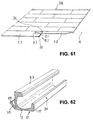
- An in Fig. 61 schematically indicated floor 34 is composed of several building panels 1.1, 1.2 described above, which are locked at their narrow sides on the separate connector and on the long sides via conventional, not shown tongue and groove connections.
- the foot 12.1 has an inclined side surface 24, the angle of inclination of the angle ⁇ (see. Fig. 2 ) is equal to. Furthermore, the foot 12.1 has a base 27 and one of the base 27 opposite, elongated upper Edge 16, which adjoins the said part-cylindrical inner surface 4.
- An essential feature of the head piece 5.1 is its upper pressure surface 18, which is bounded on the inside by a further oblique sliding surface 22.
- the pressed into the building panel 1.1 profile 2.1 is also in FIGS. 3 and 4 shown.
- the head piece 5.1 is in contact with the upper groove flank 13 and protrudes beyond the impact surface 7.1.
- the foot 12.1 is supported with its base 27 at the bottom 35 and with its side surface 24 against the inner surface 17 of the lip 15.
- the wall 3 in turn is supported with its arcuate, lower base part 42 on the trough 36 (see. Fig. 3 ). In this way, the profile 2.1 is fixed to the building panel 1.1 and secured against falling out of the seat 60.
- leg 43 of the wall 3 is flexible. Since the leg 43 carries the head piece 5.1, the latter is also pivotable relative to the base part 42 or rotatably arranged.
- FIGS. 5, 6 and 56 is shown the pivoting down of the Schmidtpaneels 1.2 on the substrate 11.
- the Schmidtpaneel is about the pivot axis A (see. Fig. 61 ) turned.
- the locking element 20 moves down. It slides over the abutment surface 7.1 of the already laid building panel 1.1 until it abuts with its oblique pressure surface 21 against the head piece 5.1 (see. FIGS. 5 and 6 ). Thereafter, the locking member 20 slides with its Andschreibfiguration 21 over in Fig. 8 shown pressure and sliding surfaces 22, 18 of the head piece until it is pivoted in the direction of groove bottom 10 and enters the in Fig. 7 shown locking position in which the head piece 5.1 in the v-shaped transition 25 of the slope 19 to the locking element 20.
- the profile is 2.1 when pivoting down the Jacobishaweels 1.2 in the direction of the bottom 35 of the already laid building panel 1.1 torsion, in which the head piece 5.1 is gradually rotated so that first one of the pivot axis A of the building panel facing end 31 and then a second end 32 of the profile completely under the upper groove edge 13 pass.
- Torsion is to be understood in the present case, the distortion of only a portion of the profile, namely the leg 43 and the head piece 5.1, while the foot 12.1 remains immobile in its position.
- the Fig. 10 shows a connector 2.2, which is similar to the connector 2.1 is constructed with the difference that instead of a web-shaped a solid foot 30 is provided.
- This profile shows a cross-section Q2, in which the footprint 27 of the solid foot 30 extends to the base part 42.
- the profile 2.2 can be used instead of the profile 2.1 (not shown).
- FIG. 11 Another similar profile embodiment (reference number 2.3) shows a cross section Q3 according to Fig. 11 ,
- the wall 3 has at its central segment, ie at its base part 42, a flat lower surface 29.
- An unillustrated bottom of the locking arm 14 has an adapted surface (not shown) for the profile 2.3.
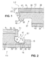
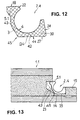
- the Fig. 12 shows a cross section Q4 of another profile 2.4, in which the solid foot 30 connects via the lower base part 42 of the profile of the arcuate, pivotable leg 43, such that the lower, level footing 27 extends to said leg 43.
- the profile 2.4 is placed with its base 27 on the flat bottom 35 of the locking arm 14. The width of the bottom 35 is equal to the base 27.
- the leg 43 is pivotable about a transition region 45 of the profile, which corresponds to the transition of the bottom 35 in the inclined groove flank 23.
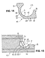
- the Fig. 14 shows a cross section Q5 of another profile 2.5, which 2.4 is almost identical to the profile.
- the profile 2.5 is stepped in its transition region 45 to the leg 43.
- the base part 42 of the profile 2.5 has a flat, lower outer surface 44, which extends between the side surface 24 of the lip 15 and a gradation 51 of the wall 3.
- the gradation 51 on the profile 2.5 matches a relatively low groove flank 33.1 of a groove 61 incorporated on the bottom of the locking arm 14 (cf. Fig. 15 ).
- the connector inserted into the groove 61 2.5 presses with its head piece 5.1 against the upper groove flank 13 of the first groove 9. In this way, the connector 2.5 is placed securely in place in the seat of the building panel 1.1 while leaving the required mobility of the head piece 5.1 supporting leg 43rd ,
- the Fig. 18 shows a further cross section (reference numeral Q15) of a profile 2.15, in which a further development of the in Fig. 8 represented Profile 2.8 acts.
- the part-cylindrical inner surface 4 of the profile 2.15 goes from the upper edge 16 of the foot 12.1 starting in a flat, reaching to the head piece 5.1 surface portion 63 on.
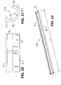
- the head piece 5.1 is bevelled at both ends 31, 32 of the profile 2.7 respectively, resulting in an insertion edge 49.1, 49.2.
- the profile 2.15 is also in FIGS. 20, 21 and 22 shown.
- a free inner edge 75 arranged on the head piece 5.1 extends in a straight line along the overall length L of the connector and has no introduction edges. Otherwise the profile is with the in FIGS. 17 to 19 shown identical.
- a cross-section Q6 of another profile 2.6 is shown.
- the foot 12.4 has two thickness dimensions: a thickness a in the upper edge region and a smaller thickness b in the lower, ending with the base surface 27 area.
- the head piece 5.2 has the aforementioned pressure surface 18 and sliding surface 22, but is on both ends 31, 32 of the profile with bevelled lead edges 49.1, 49.2 (see. Fig. 24 ) Mistake.
- the upper, planar pressure surface 18 merges into the sliding surface 22 via a slightly sloping section 76.
- the profile 2.6 has an outwardly projecting, running in the longitudinal direction of the profile, bead-like projection 48.1, which is located in a transition region 47 of the base member 42 to the movable leg 43.
- Fig. 25 shows the projection 48.1 in the inserted state in contact with the bottom 35 of the locking arm 14 and with a perpendicular to the bottom 35 arranged, relatively low groove flank 33.2 of a groove 62.
- the groove 62 is defined by said groove flank 33.2, the inner surface 17 of the lip 15 and the bottom 35 with the trough 36.
- the locking element 20 (see. Fig. 25 ) is bounded by the inclined pressing surface 21.1, a subsequent to the pressing surface 21.1, perpendicular to the effective surface 6, second pressing surface 21.2 and bounded by an inclined support surface 64 on which the head piece 5.2 is supported with its lower surface 65.
- the inclined support surface 64 forms, together with the slope 19, an asymmetrical, V-shaped groove 66, into which the head piece 5.2 is inserted such that it with its pressure surface 18, the upper groove flank 13 of the first groove 9 and with its lower pressure surface 65, the inclined Support surface 64 contacted.
- the planar surface portion 63 of the leg 43 is in contact with the pressing surface 21.2 of the locking element 20 (after the introduction of the locking element 20; Fig. 25 ).
- Fig. 26 is a cross-section Q7 of another, provided with a projection 48.2 profile to take 2.7, which in the Fig. 23 described parts, the head piece 5.2 and the foot 12.4, has.
- the outer surface 28 on the base 42 continues to a side surface 67 of the projection 48.2 at its free end.
- the projection 48.2 tapers in the direction of the transition region 47 of the leg 43 to the base part 42.
- the leg 43 itself has an upper, the head piece 5.2 supporting, straight leg portion 68 and a lower, adjoining the base portion 42 straight leg portion 69 ,
- the two leg portions 68 and 69 are to each other arranged at an obtuse angle ⁇ , which is about 150 ° in the present case.
- the head piece 5.2 also has the rectilinear inner edge 75.
- the bottom 35 of the locking arm 14 is slightly concave and forms together with the inner surface 17 of the lip 15 and the lip opposite groove edge 33.2, the groove 50 (see. Fig. 28b ).
- the groove flank 33.2 and the inner surface 17 of the lip 15 are inclined to each other and form an acute angle ⁇ .
- the angle ⁇ is in the present embodiment in the angular range 5 ° to 10 ° and may vary somewhat.
- the seat 60 (see. Fig. 28b ) for the accommodation of the connector 2.7 is also present in this design. It is formed by the first groove 9 and by the inclined inner surface 17 of the lip 15 and by the bottom 35, optionally the groove 50 of the locking arm 14. In this case, the profile inserted into the seat 60 presses 2.7 with its head piece 5.2 against the upper groove flank 13 of the first groove. 9
- the locking element 20 (see. Fig. 28a ) is similar to the embodiment according to FIG Fig. 25 built up. However, not only the inner surface 4 of the profile 2.7, but also the leg 43 is adapted with its leg portions 68 and 69 to the shape of the locking element 20.
- the head piece 5.2 engages in the V-shaped groove 66 and is supported with its lower pressure surface 65 on the support surface 64 of the groove 66 from.
- the support surface 64 is opposite at an acute angle ⁇ the base surface 26 inclined.
- a straight line c delimiting the angle ⁇ (cf. Fig. 28a ) forms the base surface 26 from.
- the angle ⁇ is in the present case about 10 °.
- the same arrangement of the head piece 5.2 in the inserted state also applies to the embodiment according to FIGS. 23 to 25 ,
- the connector 2.7 is secure in place in the seat 60 of the building panel 1.1 housed while leaving the required mobility of the head 5.2 supporting leg 43rd
- the Fig. 29 shows a cross section Q8 of a profile 2.8, which is similar to the profile 2.7.
- the same reference numerals designate like parts.
- the profile 2.8 has a foot 12.2, which differs from the foot 12.4 by a rounding 70.
- An outwardly projecting projection 48.3 points with its free, bent end 71 upwards.
- the projection 48.3 may be referred to as web-shaped.
- the head piece 5.2 is chamfered at both ends 31, 32 of the profile 2.8 in each case by an insertion edge 49.1, 49.2.
- profile 2.8 is in Fig. 31 shown.
- the profile 2.8 is with its base 42 as well as in the embodiment according to Fig. 28a , pressed into the groove 50.
- the head piece 5.2 engages in the inserted state in the V-shaped groove 66 and is supported with its lower pressure surface 65 on the support surface 64 of the groove 66 from.
- FIGS. 32 and 33 the same profile 2.8 is shown without introduction edges. Accordingly, the head piece 5.2 on the rectilinear inner edge 75.
- Fig. 34 a cross section Q9 of a profile 2.9, which instead of the projection has an outwardly projecting, stabilizing web 55, which is significantly higher than that in Fig. 29 shown projection 48.3 is.
- the web 55 is elastically deformable, so that with its outer surface 73 - in the inserted state - can be supported on the oblique groove flank 23 of the groove 9 under tension.
- This situation is the one Fig. 35 refer to.
- the leg 43 terminates with a head piece 5.3, the upper pressure surface 18 and a in FIGS. 34 and 36 clearly shown, rounded sliding surface 53 has.
- the head piece 5.3 is also distinguished by the abovementioned lower pressure surface 65, which in the assembled state (cf. Fig. 35 ) is inclined slightly upwards and the same, in the Fig. 28a forms shown angle ⁇ .
- the base part 42 of the head piece 5.3 ends with a foot 12.3, the upper inner surface 54 with the side surface 24 forms an acute angle ⁇ .
- the foot 12.3 tapers in its upper region in the direction of the edge 16.
- the inner surface 4 of the wall 3 and the rounded lower surface of the locking element 20 are teilelliptisch.
- the locking element 20 is on the one hand by the flat pressure surfaces 21.1; 21.2 and on the other hand limited by a flat inner surface 59, which merges into the aforementioned, downwardly open recess 37 on the building panel 1.2.
- the locking element 20 presses with its pressing surfaces 21.1; 21.2 against the rounded sliding surface 53 of the head piece 5.3 until it engages in the trapezoidal groove 52 and the leg 43 is brought into contact with the pressing surface 21.2.
- the inner surface 59 of the locking element 20 is in contact with the upper inner surface 54 of the foot 12.3.
- the contacting inner surfaces 54; 59 form with the effective area 6 of the building panels in Fig. 35 shown obtuse angle ⁇ 2 .
- the recess 37 spreads slightly downwards in its upper region.
- FIG. 37 shown cross section Q10 describes a profile 2.10, in which the already in Fig. 23 represented foot 12.4 is present. Otherwise profile 2.10 will have the same parts as profile 2.9 (cf. Fig. 34 ) and is denoted by the same reference numerals.
- the head piece 5.3 also has the slightly upwardly inclined, lower pressure surface 65, which in the inserted state (see. Fig. 38 ) is adapted to the inner surface 59 of the locking element 20 and contacted with this.
- the inner surface 59 of the locking element 20 at the same time forms a groove flank of the recess 37.
- the recess 37 tapers slightly downward.
- the two inner surfaces 54, 59 contacting one another are arranged at an acute angle ⁇ 1 with respect to the useful surface 6. If one draws a perpendicular T to the effective area 6, said inner surfaces 54, 59 are at an acute, complementary angle ⁇ 3 with respect to the vertical T, the sum of both angles ⁇ 1 , ⁇ 3 being 180 °.
- the lower pressure surface 65 of the rounded head piece 5.3 is inclined at the aforementioned acute angle ⁇ with respect to the base surface 26.
- Figures 39 and 40 the profile 2.10 is shown in two perspective views. The figures show that the head piece 5.3 also has the rectilinear inner edge 75 without insertion edges.
- Fig. 41 is a cross-section Q11 another, denoted by 2.11 profile shown.
- the profile 2.11 is in more Figures 43 and 44 in perspective views and in Figures 45, 46 shown in plan view of the interior of the profile and on the top of the head piece 5.3.
- the inner surface 4 of the wall 3 and the rounded lower surface of the locking element 20 are teilelliptisch.
- An essential feature of the profile 2.11 are outwardly projecting, elastically deformable, rectangular tongues 56.1, 56.2, 56.3, 56.4, 56.5, which consist of a transition region 47 (cf. Fig. 42 ) of the base part 42 to the movable leg 43, starting obliquely opposite the undeformed leg 43.
- the tongues 56.1, 56.2, 56.3, 56.4, 56.5 are manufactured in a piece of material with profile 2.11 by injection molding.
- the protruding tongues 56.1, 56.2, 56.3, 56.4, 56.5 each form a window 58.1, 58.2, 58.3, 58.4, 58.5 in the material of the wall 3.
- the profile 2.11 is provided with two insertion edges 49.1, 49.2.
- the execution of profile 2.11 according to Fig. 43 does not provide any introductory edges.
- the protruding tongues 56.1, 56.2, 56.3, 56.4, 56.5 are at the same inner distance d (cf. FIGURE 43 and 46 ) are arranged from each other along the profile.
- profile 2.11 is in Fig. 42 shown.
- the locking element 20 presses against the base part 42 of the profile, wherein the head piece 5.3 engages in the trapezoidal groove 52 and the leg 43 is in contact with the pressing surface 21.2.
- the contacting inner surfaces 54; 59 form with the effective area 6 of the building panels in Fig. 42 shown acute angle ⁇ . 1
- the recess 37 tapers slightly downwards.
- the spring-elastic tongues 56.1, 56.2, 56.3, 56.4, 56.5 deform and are braced against the oblique groove flank 23 of the first groove 9.
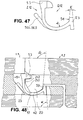
- Fig. 47 Of the Fig. 47 is a cross section Q12 of another, provided with tongues 56.1, 56.2, 56.3, 56.4, 56.5 profile to take 2.12.
- the difference to in Fig. 41 shown profile 2.11 is that his foot 12.3 similar to the profile 2.9 (see. Fig. 34 ), tapers upwards in its upper area.
- the inner surface 4 of the wall 3 of the profile 2.12 and the rounded lower surface of the locking element 20 are partially elliptical.
- Fig. 49 is the profile 2.12 in a perspective view towards the inside of the profile and in Figures 50, 51 shown in plan view of the interior of the profile and on the top of the head piece 5.3.
- the figures show that the head piece 5.3 has the rectilinear inner edge 75 without insertion edges.
- the used profile 2.12 is in Fig. 48 shown.
- the inner surface 54 of the foot 12.3 forms the obtuse angle ⁇ 2 with the inner surface 59 of the locking element 20.
- the resilient tongues 56.1, 56.2, 56.3, 56.4, 56.5 are based on the inclined groove flank 23 of the first groove 9 in a taut manner.
- Fig. 52 is a further cross-section (reference Q13) of a designated 2.13 profile shown in the Fig. 37 cross section Q10 (profile 2.10) is very similar.
- the profile 2.13 has a rounded head piece 5.4, the lower pressure surface 65 is arranged at an angle to the flat surface portion 63 on the inside of the leg 43.
- the inserted state cf. Fig. 53
- the mutually contacting inner surfaces 54; 59 with the effective area 6 of the building panel the already shown acute angle ⁇ . 1
- Another arrangement, for example, with obtuse angle ⁇ 2 of the contacting inner surfaces 54; 59 is possible.
- the Fig. 54 shows a cross section Q14 of a designated 2.14 profile whose details differ from the profile 2.10 (see. Fig. 37 ).
- the difference between the two profiles is that the profile 2.14, in contrast to the profile 2.10 has a head 5.5 with a downward in the direction of the foot 12.4 inclined pressure surface 65.
- the pressure surface 65 In the inserted state of the connector (see. Fig. 55 ) forms the pressure surface 65 with the useful or base surface 6, 26 of the building panels a sharp angle ⁇ .
- the size of the angle ⁇ is about the size of the in Fig. 38 imaged angle ⁇ . Accordingly, the angle ⁇ in the present case about 3 ° to 5 ° and of course may vary. However, the angle ⁇ should be at least 2 ° in terms of advantageous self-locking of the two surfaces in contact.
- the inner surface 4 and the outer surface 28 of the wall 3 extends from the foot 12.4 beginning to the transition 47 to the movable leg 43 teilellipston.
- FIG. 58 and 62 a further connector (reference number 2.16) is shown whose cross-section Q16 is approximately a combination of the cross-section Q2 (see FIG. Fig. 10 ) and the cross section Q9 (cf. Fig. 34 ).
- the connector has 2.16 already described head piece 5.3 with a slightly inclined pressure surface 65, the protruding web 55 and a web-shaped upwardly facing foot 77, whose lower, bounded by the footing 27 part similar to the foot 30 according to Fig. 10 is executed without bottom gradation.
- the base 27 is flat and merges into the slightly rounded lower outer surface 28 of the wall 3.
- the adapted to the connector 2.16 side surfaces 8.1, 82 of the building panels 1.1, 1.2 are detailed in FIGS. 56 and 57 as in Fig. 59 shown.
- the chunky locking element 20 of the building panel 1.2 is by the lower, inclined pressure surface 21.1, the lateral, perpendicular to the effective surface 6 extending pressure surface 21.2, the downwardly rounded surface 46 and the pressing surfaces 21.1, 21.2 facing away from inner surface 59 and by the support surface 64 of the groove 52 limited.
- the inner surface 59 is arranged perpendicular to the effective surface 6, but it may also be slightly inclined.
- an upper, inner bevel 80 and a further, smaller outer bevel 81 can be seen on the lip 15 of the building panel 1.1. Furthermore, the upper groove flank 13 of the groove 9 connects via a chamfer 82 to the abutment surface 7.1 of the building panel 1.1.
- the chamfers 80, 82 facilitate the placement of the connector 2.16 in the seat 60, especially when the connectors are to be pressed in using an unillustrated machine.
- the inner surface 17 of the lip 15 is arranged perpendicular to the base surface 26 of the building panel 1.1, so that a right angle ⁇ between the inner surface 17 and a planar surface portion 78 of the bottom 35 results. In the inserted state of the connector 2.16 (see. Fig.
- the connector is also 2.16 secure in the seat 60 of the building panel 1.1 housed while leaving the required mobility of the head piece 5.3 supporting leg 43rd
Abstract
Description
- Die Erfindung betrifft ein Baupaneel mit einer Einrichtung zur Verbindung mit wenigstens einem weiteren gleichartigen Baupaneel auf einem Untergrund, wobei das Baupaneel dazu vorgesehen ist, gegen ein bereits verlegtes Baupaneel abgesenkt zu werden, wobei
- das Baupaneel jeweils gegenüberliegende erste und zweite profilierte Seitenflächen aufweist, an denen je eine Stoßfläche angeordnet ist, die senkrecht zu einer Nutzfläche bzw. Basisfläche des Baupaneels liegt,
- die Stoßfläche der ersten Seitenfläche in eine entlang der Seitenfläche des Baupaneels verlaufende, erste Nut übergeht,
- über die Stoßfläche der ersten Seitenfläche des Baupaneels ein Verriegelungsarm hinausragt,
- der Verriegelungsarm in eine zur Nutzfläche gerichtete Lippe ausläuft, die wiederum eine in einen Boden des Verriegelungsarms auslaufende Innenfläche aufweist,
- die erste Nut einen gegenüber der Stossfläche der ersten Seitenfläche zurückversetzten Nutboden aufweist,
- in die erste Nut des Baupaneels ein länglicher, wenigstens teilweise flexibler, separater Verbinder wenigstens teilweise eingelassen ist, der im verlegten Zustand der Baupaneele mit der zweiten Seitenfläche eines gegenüberliegenden Baupaneels zusammenwirkt,
- der Verbinder einen etwa dachrinnenförmigen Querschnitt aufweist und eine wenigstens teilweise bogenförmige, aus einem Basisteil und einem Schenkel bestehende Wandung besitzt,
- die Wandung mit einer wenigstens teilweise teilzylindrischen oder teilelliptischen Innenfläche an einer Kante dieser Innenfläche - im Querschnitt des Verbinders gesehen
- in ein Kopfstück und an einer anderen Kante in einen Fuß übergeht,
- der Fuß eine nach außen gerichtete, im eingesetzten Zustand der Innenfläche der Lippe zugewandte Seitenfläche und eine sich an die Seitenfläche anschließende Standfläche aufweist,
- das Kopfstück des Verbinders im eingesetzten Zustand des Verbinders in Richtung Nutzfläche zeigt,
- der sich an das Basisteil anschließende Schenkel, der in das Kopfstück ausläuft, im eingesetzten Zustand des Verbinders beweglich angeordnet ist, so dass beim Zusammenfügen von Baupaneelen der Schenkel mitsamt Kopfstück in Richtung des Nutbodens verschwenkt werden kann,
- die zweite Seitenfläche ein Verriegelungselement aufweist, welches beim Zusammenfügen zweier Baupaneele in den von der Innenfläche des Verbinders aufgespannten Innenraum des gegenüberliegenden Baupaneels eingreift,
- das Verriegelungselement in eine in Richtung Basisfläche offene Ausnehmung des Baupaneels übergeht,
- der Boden des Verriegelungsarms und die erste Nut sowie die Innenfläche der Lippe einen Sitz für die Unterbringung des Verbinders bilden,
- und wobei das Kopfstück im in die erste Nut eingepassten Zustand des Verbinders wenigstens teilweise gegen eine erste Nutflanke der besagten Nut drückt.
- Ein Baupaneel mit einer solchen Einrichtung ist aus
WO 2008/004960 bekannt. In eine halbrunde Ausnehmung eines bereits verlegten Baupaneels ist gemäß Figuren 6a bis 6d ein etwa boomerangförmiger, schaukelartig wirkender Verbinder eingesetzt, der durch ein Gegenpaneel unter Hebelwirkung bewegt wird, bis ein dickerer Rand des Verbinders - im Querschnitt der Paneelverbindung gesehen - in eine zu dem Rand kompatible Nut des Gegenpaneels einspringt. Der separate Verbinder hat die Aufgabe, die Verriegelung der Baupaneele im Wesentlichen senkrecht gegenüber der Trittfläche zu gewährleisten. Die Aufgabe der horizontaler Verriegelung übernimmt auf herkömmlicher Weise der Verriegelungsarm mit seiner Lippe. Zwar verfügt der bekannte Verbinder über eine zusätzliche, auf das Gegenpaneel gerichtete eigene Lippe, sorgt diese allerdings lediglich für eine Verstärkung der vorhandenen horizontalen Verriegelung. Nachteilig bei der bekannten Einrichtung ist, dass der Verbinder vor dem Zusammenfügen beider Baupaneele relativ leicht aus der Befestigung in der Nut herausfallen kann, insbesondere dann, wenn das Material des Verbinders federelastisch ist. Die Stabilität der Verbindung scheint unzureichend zu sein. -
DE 20 2009 004 530 U1 beschreibt Fußbodenpaneele mit Kupplungsteilen, welche ein horizontal und ein vertikal aktives Verriegelungssystem bilden, umfassend einen separaten Verbinder aus einem coextrudierten Kunststoff-Streifen mit Bereichen von unterschiedlichen Eigenschaften und spezieller unterschiedlicher Flexibilität, wobei einen Bereich des Verbinders ein Scharnier darstellt, das den Verbinder in ein Basisteil mit Fuß und ein auf den Boden des Paneels gerichtetes Kopfstück teilt. Nachteilig ist, dass der Verbinder, insbesondere dessen Fuß beim Einmontieren des Verbinders relativ leicht aus seinem Sitz herausfallen kann. - In
DE 102 37 397 A1 sind unterschiedliche Ausführungsformen eines elastischen, ein- oder zweiteiligen Verbinders mit Hohlkammern dargestellt, der einem Fensterdichtungsprofil ähnelt. Außerdem ist derFig. 5 ein ankerartiger, aus zwei Teilen bestehender Verbinder zu entnehmen, bei dem ein über eine Seitenfläche des einen Paneels ragender Mittelsteg, Stempel genannt, in einen Inneraum eines in eine Nut eines zweiten Paneels hinein gepressten C-Profils mit Kopfstück eingreift. Die profilierten Seitenflächen der beiden miteinander verbundenen Paneele verlaufen im Wesentlichen schräg zur Trittfläche der Paneele, wobei die gekoppelten Teile des Verbinders senkrecht auf die Seitenflächen gerichtet sind. Dabei sind beide Teile des Verbinders spiegelsymmetrisch zu seiner Längsachse aufgebaut. Nachteilig bei einer so ausgestalteten Paneelverbindung mit zweiteiligem Verbinder gemäßFig. 5 ist, dass eine nachträgliche Trennung der miteinander verbundenen Fußbodenpaneele nicht realisierbar ist. Auch eine Verbindung der Fußbodenpaneele miteinander bzw. ihre Verlegung auf einen Untergrund scheint problematisch zu sein, weil eine Montage in Horizontalrichtung mit Hilfe des bekannten Schlagklotzes unmöglich und Montage mit Schwenkbewegung besonders erschwert ist. - Bei
WO00/47841 A1 - Außerdem sind mehrere Ausführungen von anderen schaukelartig wirkenden Verbindern bekannt.
- Aufgabe der Erfindung ist, eine alternative gattungsgemäße Einrichtung zur Verbindung von polygonalen, plattenförmigen Baupaneelen miteinander mit Hilfe der separaten Verbinder zu entwickeln, die nicht schaukelartig wirken und deren Halt am Baupaneel sicher und stabiler ist.
- Diese Aufgabe ist durch eine Einrichtung der eingangs genannten Art gelöst, bei der
- der Fuß des Verbinders mit seiner Seitenfläche und mit seiner Standfläche sowie das dem Boden zugewandte Basisteil des Verbinders die besagte Innenfläche der Lippe und den Boden des Verriegelungsarms vor und nach dem Zusammenfügen zweier Baupaneele wenigstens teilweise kontaktieren,
- wobei die Lippe des Verriegelungsarms sich in Richtung Bodenschicht derart verjüngt, dass die Innenfläche der Lippe unter einem spitzen oder rechten Winkel zum Boden des Verriegelungsarms bzw. zur Basisfläche des Baupaneels geneigt ist,
- und wobei das Verriegelungselement wenigstens eine ebene Andrückfläche aufweist, die bei der Verbindung zweier Baupaneele gegen das Kopfstück stößt, so dass das Kopfstück in Richtung Nutboden verschwenkt wird.
- Die Ähnlichkeit zwischen den Verbindern gemäß Erfindung und herkömmlichen, etwa halbrunden oder teilelliptischen Dachrinnen kann dadurch begründet werden, dass das Kopfstück des Verbinders etwa der Tropfkante der Dachrinne und der Fuß dem der Tropfkante abgewandten Rinnenwulst der Dachrinne entspricht.
- Im Weiteren wird das Baupaneel, das gegen das bereits verlegte herab geschwenkt wird, als Gegenpaneel bezeichnet. Die Begriffe, wie "oben", "obere", "unten", "untere", "unterhalb", "oberhalb" etc. beziehen sich auf die auf einen Untergrund verlegten Baupaneele, wie dies auch in der Zeichnung dargestellt ist. Ferner wird der separate Verbinder als Profil bezeichnet.
- Bei der Einrichtung gemäß Erfindung handelt es sich annähernd um solche, die eine sogenannte Hakenverbindung beinhaltet, bei der normalerweise die die Hakenverbindung bildenden Teile: Lippe am Verriegelungsarm und das auf den Boden gerichtete Verriegelungselement des Gegenpaneels miteinander dicht verhakt sein sollen und die Stoßflächen der beiden Baupaneele in flächigen Kontakt miteinander gebracht werden sollen, um die Verriegelung der Baupaneele in horizontaler Richtung zu sichern. Für die bekannte Lösung gemäß
WO 2008/004960 kann diese Voraussetzung auch dann erfüllt werden, wenn der Verbinder aus der Nut herausgenommen wird. Der separate Verbinder gemäßWO 2008/004960 liegt außerhalb der Flächen, die die eigentliche Hakenverbindung bilden. - Es ist nicht zu übersehen, dass die Hakenverbindung bei der erfindungsgemäßen Lösung erst nach dem Zusammenfügen der beiden Baupaneele zustande kommt, indem sich zwischen der Innenfläche der Lippe und des beim Zusammenfügen der Baupaneele in den Verbinder eingreifenden Verriegelungselementes der stegförmige Fuß befindet. Sollte der Verbinder herausgenommen werden, kann wegen entstandener Spalte nicht über eine Hakenverbindung die Rede sein. In dieser Lage wären die beiden Baupaneele vor dem Verschieben zueinander sowohl in horizontaler als auch in vertikalen Richtung nicht gesichert. Von großem Vorteil ist, dass das Profil gemäß vorliegender Erfindung eine Verriegelung zugleich in beiden Richtungen gewährleisten kann.
- Vorzugsweise ist der separate Verbinder gemäß Erfindung aus Kunststoff angefertigt. Als Kunststoffe für den Verbinder kommen Thermoplaste, wie Polyethylen (PE), Polypropylen (PP), Polystyrol (PS), Polyamide (PA), Polycarbonate (PC), Polyethylenterephthalat (PET) u. a., sowie sogenannte technische Kunststoffe, wie Styrol-Copolymerisate (ABS), Polyamide (PA), Polycarbonate (PC), Polyethylenterephthalat (PET), Polymethylmethacylat (PMMA), Polyoxymethylen (POM), Fluorkunststoffe (Teflon), Polyurethane (PUR) in Frage.
- Der Fuß des Profils kann stegförmig und/oder massiv sein, wobei von entscheidender Bedeutung ist, dass dieser eine nach innen geneigte Seitenfläche aufweist, die mit der Innenfläche der Lippe - im eingesetzten Zustand - zumindest teilweise in Kontakt steht. So kann der Neigungswinkel der Seitenfläche des Fußes zu seiner Standfläche dem besagten scharfen Winkel an der Lippe entsprechen. Wenn die Innenfläche der Lippe rechtwinklig zum Boden des Verriegelungsarms bzw. zur Basisfläche des Baupaneels angeordnet ist, kann der Fuß mit seinem unteren Teil gegen die besagte Innenfläche drücken. So kann der Fuß und der untere Teil des einmontierten Verbinders nahezu formschlüssig, und zwar vor und nach der Absenkung des Gegenpaneels an dem Verriegelungsarm anliegen.
- Der Verbinder kann in einem Übergangsbereich seines Basisteils zum beweglichen Schenkel wenigstens einen nach außen ragenden, in Längsausrichtung des Verbinders verlaufenden Vorsprung aufweisen. Der Vorsprung kann im eingesetzten Zustand des Verbinders mit der Nutflanke der zweiten Nut in Kontakt stehen.
- Das Profil kann auch aus sogenannten Integral-Kunststoffen hergestellt sein. Ein solches Profil kann beispielsweise einen harten Fuß und einen relativ weichen, sich an das Kopfstück anschließenden Schenkel aufweisen. Dabei kann das Kopfstück und der Fuß steifer als das rechtliche Material des Profils ausgeführt sein. Das Profil kann glatte und/oder aufgeraute Oberflächen haben.
- Ferner kann das Profil aus Metall, Holzwerkstoff oder Verbundstoff gefertigt sein.
- Das Profil kann wenigstens in seinem Schenkelbereich elastisch verformbar sein. Die Elastizität des Profils kann durch entsprechende Verengungen oder sanfte Übergange des Schenkels zum Fuß unterstützt sein.
- Das Kopfstück kann eine streifenförmige, ebene, im eingesetzten Zustand der ersten Nutflanke zugewandte Druckfläche aufweisen, die sich wiederum in eine - im Querschnitt des Profils gesehen - nach unten zeigende, schräge oder abgerundete Gleitfläche fortsetzt.
- Vorzugsweise verläuft die erste, obere Nutflanke der Nut zur Aufnahme des Profils parallel und die zweite, untere Nutflanke schräg zur Nutz- bzw. Basisfläche des Baupaneels, wobei die untere Nutflanke in den Boden des Verriegelungsarms übergeht. Die beiden Nutflanken schließen sich an einen senkrecht zur Nutzfläche angeordneten Nutboden der besagten Nut an. So konfigurierte Nut hat genügend Platz zum Verschwenken des Kopfstücks. Die ebene Druckfläche des Kopfstücks verbleibt im nicht durch das herabsenkende Gegenpaneel hervorgerufenen, gespannten Zustand in flächigem Kontakt mit der oberen Nutflanke oder drückt gegen sie.
- Der Boden des Verriegelungsarms verläuft vorzugsweise parallel zur Basisfläche und bildet dann eine Stützfläche für den Fuß und für den unteren Teil der Wandung des Verbinders. Zur Aufnahme eines massiven Fußes, dessen ebene Standfläche sich breiter als die des stegförmigen Fußes erstreckt, eignet sich insbesondere ein ebener oder abgestufter Boden.
- Am Boden des Verriegelungsarms kann wenigstens eine parallel zur Nut verlaufende Mulde eingearbeitet sein, die vorzugsweise etwa in der Mitte des Bodens, auf jeden Fall außerhalb der unteren geneigten Nutflanke liegt. An die Mulde kann sich der untere Teil des eingelegten Profils, also sein Basisteil abstützen. Für das einmontierte Profil gemäß Erfindung gilt also das Prinzip zumindest dreier Kontaktflächen dieses Profils mit dem unteren Baupaneel, nämlich mit der geneigten Innenfläche der Lippe, mit dem Boden des Verriegelungsarms und mit der oberen Nutflanke der ersten Nut. So festgelegtes Profil sitzt sicher an der Seitenfläche des unteren Baupaneels und hat kaum Chance, sich selbstständig zu lösen.
- Bei einer besonders vorteilhaften Ausführungsform der Erfindung sind vier Kontaktflächen des Profils mit dem unteren Baupaneel vorgesehen, wobei die vierte Kontaktfläche durch einen von dem Profil herab stehenden, federnden Steg oder wenigstens eine herab stehende, federnde Zunge entstanden ist, die im eingesetzten Zustand gegen die untere, schräge Nutflanke der ersten Nut drückt. Hierdurch wird eine noch stabilere Lage des in den Sitz untergebrachten Profils erzielt.
- Das Kopfstück kann beim Herabschwenken des Baupaneels in Richtung Boden des bereits verlegten Baupaneels eine Drehbewegung um die Mulde bzw. um eine Abstufung des Bodens des Verriegelungsarms ausüben. Verschwenkt wird also der Schenkel des Profils. Dabei können der Fuß des Verbinders in seiner Lage an der Innenfläche der Lippe sowie und der Basisteil des Profils unbeweglich verbleiben.
- Die Profile können manuell oder mechanisch bzw. mit Hilfe eines Automaten werkseitig in die vorhandene Nut des Baupaneels eingedrückt sein. Die mit den Profilen versehenen Baupaneele können in dieser Form gelagert und vertrieben werden.
- Wenn das Profil aus Kunststoff hergestellt wird, kann es preiswert als Massenartikel zur Verfügung gestellt werden.
- Die Profile gemäß Erfindung sind im Wesentlichen für die Schmalkanten der Baupaneele bestimmt. Allerdings können auch in den längeren Seitenflächen der Baupaneele integriert sein, wenn diese an den separaten Verbinder entsprechend angepasst werden.
- Vorteilhaft ist, wenn an dem am Gegenpaneel befindlichen Verriegelungselement eine schräg gegenüber der Nutztfläche angeordnete Andrückfläche eingebracht ist, mit der auf die plane Druckfläche, aber vor allem auf die abgerundete oder abgeschrägte Gleitfläche des Kopfstücks ein Druck ausgeübt wird. Die schräge Andrückfläche des nach unten gerichteten Verriegelungselementes liegt unter einem Winkel ≥ 45°, vorzugsweise 60° gegenüber der Nutzfläche. Diese Winkelgröße gewährleistet ein optimales Gleiten des Verriegelungselementes am Kopfstück, ohne dass das Kopfstück aus dem Sitz herausfallen kann.
- Die abgerundete Oberfläche des Verriegelungselementes kann in eine gegenüber der oberen Stoßfläche des Baupaneels zurückversetzte Schräge übergehen, derart, dass ein scharfer, etwa V-förmiger Übergang zur Aufnahme des Kopfstücks gebildet ist.
- Das Kopfstück kann aber auch in eine Nut des das Verriegelungselement tragenden Baupaneels eingreifen. Vorzugsweise ist die Nut etwa rechteckig oder trapezförmig.
- Vorteilhaft ist, dass die abgerundete Oberfläche des Verriegelungselementes über eine schräg oder senkrecht gegenüber der Nutzfläche angeordnete, ebene Fläche in die nach unten offene Ausnehmung des die Verriegelungselement tragenden Baupaneels übergeht. Dabei kann eine streifenförmige Innenfläche des oberen Teils des Fußes vorgesehen sein, die zu der besagten ebenen Fläche kompatibel ist.
- Die Baupaneele als solche können aus Kunststoff, Metall, Holzwerkstoff, darin Papier oder anderen nachwachsenden Rohstoffen, wie Kork, hergestellt sein. Die Baupaneele können in Massiv- oder Schichtbauweise, wie an sich bekannte HDF- oder MDF-Paneele, gefertigt sein und ein Holz- oder Fliesendekor aufweisen, das mit mindestens einer Schicht aus einem transparenten oder transluzenten Kunstharz abgedeckt ist. Die Baupaneele können mit antibakteriellen und/oder feuerhemmenden Mitteln ausgerüstet sein.
- Die Baupaneele können als Fußbodenpaneele, als Wandverkleidungspaneele oder als Möbelteile Verwendung finden.
- Ausführungsbeispiele der Erfindung sind anhand der Zeichnung näher erläutert. Die Figuren zeigen:
- Figuren 1 und 2
- zwei Baupaneele jeweils im Bereich ihrer Seitenfläche, ohne Verbinder, jeweils in einem Schnitt,
- Figuren 3 und 4
- jeweils ein Baupaneel mit eingelegtem Verbinder, in zwei Stellungen des Kopfstücks, jeweils in einem Schnitt,
- Figuren 5 bis 7
- jeweils zwei Baupaneele mit eingelegtem Verbinder, in drei Stellungen des herab schwenkenden Baupaneels, jeweils in einem Schnitt,
- Fig. 8
- einen Verbinder in einer ersten Ausführungsform, im Querschnitt des Profils,
- Fig. 9
- den Verbinder gemäß
Fig. 8 in einer perspektivischen Ansicht; - Fig. 10
- einen Verbinder mit einem massiven Fuß, im Querschnitt des Profils,
- Fig. 11
- eine Abweichungsform des in
Fig. 8 dargestellten Verbinders, ebenso im Querschnitt des Profils, - Fig. 12
- einen anderen Verbinder, mit massivem Fuß, im Querschnitt des Profils,
- Fig. 13
- den Verbinder gemäß
Fig. 12 , angeordnet zwischen der Lippe und der seitlichen Nut eines Baupaneels, in einem Schnitt, - Fig. 14
- einen weiteren Verbinder mit massivem Fuß, im Querschnitt des Profils,
- Fig. 15
- den Verbinder gemäß
Fig. 14 , angeordnet zwischen der Lippe und der seitlichen Nut eines Baupaneels, in einem Schnitt, - Fig. 16
- verlegte Baupaneele gemäß
Figuren 1 und 2 , jedoch ohne Verbinder, in einem Schnitt; - Figuren 17 und 18
- einen anderen Verbinder, mit abgeschrägten Enden des Kopfstücks, in einer Draufsicht auf eine Seitenfläche seines Fußes und in einer das Profil zeigenden Seitenansicht des Verbinders;
- Fig. 19
- den Verbinder gemäß
Figuren 17 und 18 in einer perspektivischen Ansicht; - Figuren 20 und 21
- den Verbinder gemäß
Figuren 17 und 18 , ohne abgefasten Enden des Kopfstücks, in einer Draufsicht auf eine Seitenfläche seines Fußes und in einer das Profil zeigenden Seitenansicht des Verbinders; - Fig. 22
- den Verbinder gemäß
Figuren 20 und 21 in einer perspektivischen Ansicht; - Fig. 23
- einen Verbinder mit einem im Übergangsbereich seines Basisteils zum Schenkel liegenden Vorsprung, im Querschnitt des Profils,
- Fig. 24
- den Verbinder gemäß
Fig. 23 in einer perspektivischen Ansicht, - Fig. 25
- zwei miteinander verbundene Baupaneele mit eingelegtem Verbinder gemäß
Fig. 25 , in einem Schnitt, - Fig. 26
- einen Verbinder mit anderem Vorsprung, im Querschnitt des Profils,
- Fig. 27
- den Verbinder gemäß
Fig. 26 in einer perspektivischen Ansicht, - Fig. 28a
- zwei miteinander verbundene Baupaneele mit eingelegtem Verbinder gemäß
Figuren 26 und 27 , in einem Schnitt, - Fig. 28b
- die miteinander verbundene Baupaneele gemäß
Fig. 28a , mit angedeutetem konkavem Boden, in einem Schnitt; - Fig. 29
- einen weiteren Verbinder mit abgewinkelten Vorsprung und mit abgerundetem Fuß, im Querschnitt des Profils;
- Fig. 30
- den Verbinder gemäß
Fig. 29 in einer perspektivischen Ansicht; - Fig. 31
- zwei miteinander verbundene Baupaneele mit eingelegtem Verbinder gemäß
Fig. 29 , in einem Schnitt, - Fig. 32
- den Verbinder gemäß
Fig. 29 , jedoch ohne abgeschrägten Eden am Kopfstück, im Querschnitt des Profils; - Fig. 33
- den Verbinder gemäß
Fig. 32 in einer perspektivischen Ansicht; - Fig. 34
- einen Verbinder mit einem anderem, stegförmigen Vorsprung, im Querschnitt des Profils,
- Fig. 35
- zwei miteinander verbundene Baupaneele mit eingelegtem Verbinder gemäß
Fig. 34 , in einem Schnitt; - Fig. 36
- einen Abschnitt des Verbinders gemäß
Fig. 34 , in einer perspektivischen Ansicht; - Fig. 37
- einen Verbinder gemäß
Fig. 34 , jedoch mit geändertem Fuß, im Querschnitt des Profils, - Fig. 38
- zwei miteinander verbundene Baupaneele mit eingelegtem Verbinder gemäß
Fig. 37 , in einem Teilschnitt, - Figuren 39 und 40
- den Verbinder gemäß
Fig. 37 in zwei perspektivischen Darstellungen; - Fig. 41
- einen Verbinder aufweisend herab stehende Zungen, im Querschnitt des Profils,
- Fig. 42
- zwei miteinander verbundene Baupaneele mit eingelegtem Verbinder gemäß
Fig. 41 , in einem Teilschnitt, - Fig. 43
- den Verbinder gemäß
Fig. 41 in einer perspektivischen Ansicht, mit sichtbaren Zungen; - Fig. 44
- den Verbinder gemäß
Fig. 41 in einer Ansicht auf seine Innenseite; - Figuren 45 und 46
- den Verbinder gemäß
Fig. 41 in Draufsicht auf die Seitenfläche seines Fußes sowie in Draufsicht von oben auf das Kopfstück; - Fig. 47
- einen Verbinder gemäß
Fig. 41 , jedoch mit geändertem Fuß, in einem Schnitt des Profils; - Fig. 48
- zwei miteinander verbundene Baupaneele mit eingelegtem Verbinder gemäß
Fig. 47 , in einem Teilschnitt; - Fig. 49
- den Verbinder gemäß
Fig. 47 in einer Ansicht auf seine Innenseite; - Figuren 50 und 51
- den Verbinder gemäß
Fig. 47 in Draufsicht auf die Seitenfläche seines Fußes sowie in Draufsicht von oben auf das Kopfstück; - Fig. 52
- einen Verbinder gemäß
Fig. 37 , jedoch mit geändertem Kopfstück, in einem Schnitt des Profils; - Fig. 53
- zwei miteinander verbundene Baupaneele mit eingelegtem Verbinder gemäß Fig. 453, in einem Teilschnitt;
- Fig. 54
- einen Verbinder gemäß
Fig. 37 , jedoch mit anderer Variante des Kopfstücks, in einem Schnitt des Profils; - Fig. 55
- zwei miteinander verbundene Baupaneele mit eingelegtem Verbinder gemäß
Fig. 54 , in einem Teilschnitt; - Figuren 56 und 57
- zwei weitere Baupaneele, jeweils im Bereich ihrer Seitenfläche, ohne Verbinder, jeweils in einem Schnitt;
- Fig. 58
- eine weitere Ausführungsform des Verbinders, geeignet für die Baupaneele gemäß
Figuren 56 und 57 , in einem Schnitt; - Figuren 59 und 60
- die Baupaneele gemäß
Figuren 56 und 57 im verlegten Zustand, ohne und mit Verbinder, in einem Schnitt; - Fig. 61
- einen Fußboden in einer perspektivischen Ansicht von oben, und
- Fig. 62
- den Verbinder gemäß
Fig. 58 in einer perspektivischen Ansicht. - Die
Figuren 1, 2 und16 zeigen zwei Baupaneele 1.1, 1.2 vor und nach dem Herabschwenken des Baupaneels 1.2 (Gegenpaneel) in Richtung Untergrund 11, auf den das Baupaneel 1.1 bereits verlegt ist. Charakteristisch für die Figuren ist das Fehlen eines separaten Verbinders, der noch im Weiteren detailliert beschrieben werden wird. - Die beiden Baupaneele 1.1, 1.2 bestehen jeweils aus einer Nutzschicht 39, einer Bodenschicht 40 und einer dazwischen liegenden Kernschicht 38 aus Holzwerkstoff. Die Nutzschicht 39 ist mit einer Dekorschicht 41 versehen, deren Oberfläche eine Tritt- bzw. Nutzfläche 6 bildet. Die Bodenschicht 40 weist wiederum eine dem Untergrund 11 zugewandte Basisfläche 26 auf.
- Das Baupaneel 1.1 zeichnet sich durch eine profilierte, durch die Nutz- und Basisflächen 6; 26 begrenzte Seitenfläche 8.1 aus, aufweisend eine Stoßfläche 7.1, eine gegenüber der Stoßfläche zurückversetzte, erste Nut 9 und einen über die Stoßfläche 7.1 hinausragenden Verriegelungsarm 14 mit einer nach oben abstehenden Lippe 15.
- Die erste Nut 9 ist im Querschnitt polygonal und weist einen gegenüber der Stoßfläche 7.1 zurückversetzten Nutboden 10 auf, der parallel zur Stoßfläche 7.1 angeordnet ist und in eine obere, planparallel zur Nutzfläche 6 verlaufende Nutflanke 13 und eine schräg gerichtete untere Nutflanke 23 ausläuft. Die letztere geht wiederum in einen parallel zur Basisfläche 26 liegenden Boden 35 des Verriegelungsarms 14 über, wobei mitten am Boden 35 eine entlang der Seitenfläche 8.1 verlaufende Mulde 36 ausgefräst ist.
- Die Lippe 15 des Verriegelungsarms 14 ist trapezförmig und verjüngt sich in Richtung Bodenschicht 40 derart, dass an der Lippe eine unter einem spitzen Winkel α zum Boden 35 geneigte Innenfläche 17 gebildet ist. Der Winkel α liegt in vorliegendem Fall zwischen 80° und 85° und kann variieren.
- Wie die
Fig. 1 zeigt, ist von dem Boden 35 des Verriegelungsarms 14, von der Innenfläche 17 der Lippe 15 und von der ersten Nut 9 bzw. von derer oberen Nutflanke 13 ein Sitz 60 zur Unterbringung des Verbinders gebildet. - Das Baupaneel 1.2 zeichnet sich durch eine profilierte, durch die Tritt- und Basisflächen 6, 26 begrenzte Seitenfläche 8.2 aus, aufweisend eine Stoßfläche 7.2, eine gegenüber der Stoßfläche 7.2 zurückversetzte Schräge 19 und ein nach unten gerichtetes Verriegelungselement 20. Die Schräge 19 bildet zusammen mit dem Verriegelungselement 20 einen tiefen, scharfen, V-förmigen Übergang 25.
- An dem Verriegelungselement 20 ist eine Andrückfläche 21.1 gefräst, die mit der Nutzfläche 6 einen spitzen Winkel bildet und annährend parallel zur Schräge 19 angeordnet ist. Der scharfe Winkel beträgt vorzugsweise 60°. Das Verriegelungselement 20 schließt sich an eine nach unten offene Ausnehmung 37 zur Aufnahme der Lippe 15 des Baupaneels 1.1 an.
- In
Fig. 16 ist ein relativ breiter Spalt S zwischen der Verriegelungselement 20 und der Lippe 15 zu sehen, wenn die beiden Stoßflächen 7.1, 7.2 miteinander kontaktieren. Die Baupaneele 1.1, 1.2 sind dabei miteinander weder in horizontaler, noch in vertikalen Richtung verriegelt. - Eine ähnliche Lage der auf den Untergrund 11 verlegten Baupaneele 1.1, 1.2 ist der
Fig. 7 zu entnehmen. Allerdings ist hier ein separater Verbinder 2.1 (Profil) eingesetzt, derart, dass der Spalt S (vgl.Fig. 16 ) völlig von einem stegförmigen Fuß 12.1 des Profils ausgefüllt ist. Die Baupaneele 1.1, 1.2 bilden samt eingelegtem Profil 2.1 eine Einrichtung 100, bei der das Profil eine Verriegelung in beiden Richtungen (vgl.Fig. 7 , Pfeile X, Y) bewirkt. - Das etwa dachrinnenförmige Profil 2.1 (vgl.
Figuren 8 und9 ) weist einen Querschnitt Q1 auf, auf dem eine teilzylindrische Innenfläche 4, eine ebenso teilzylindrische Außenfläche 28, ein Kopfstück 5.1 und der Fuß 12.1 zu erkennen sind. Die Innen- und Außenflächen 4, 28 begrenzen eine rinnenförmige Wandung 3, die vom Kopfstück 5.1 bis zum Fuß 12.1 reicht. - Das in
Fig. 9 gezeigtes Profil 2.1 ist relativ kurz und daher für die Schmalseiten der Baupaneele bestimmt. Seine Länge L entspricht im Wesentlichen dem Ausmaß der Schmalseite oder ist geringfügig kleiner. Ein inFig. 61 schematisch angedeuteter Fußboden 34 setzt sich aus mehreren oben beschriebenen Baupaneelen 1.1, 1.2 zusammen, die an ihren Schmalseiten über die separaten Verbinder und an Längsseiten über herkömmliche, nicht dargestellte Nut-Feder-Verbindungen verriegelt sind. - Der Fuß 12.1 weist eine geneigte Seitenfläche 24 auf, deren Neigungswinkel dem Winkel α (vgl.
Fig. 2 ) gleich ist. Ferner weist der Fuß 12.1 eine Standfläche 27 und einen der Standfläche 27 gegenüberliegenden, länglichen, oberen Rand 16 auf, der sich an die besagte teilzylindrische Innenfläche 4 anschließt. - Ein wesentliches Merkmal des Kopfstücks 5.1 ist seine obere Druckfläche 18, die innenseitig von einer weiteren, schrägen Gleitfläche 22 begrenzt ist.
- Das in das Baupaneel 1.1 eingepresste Profil 2.1 ist auch in
Figuren 3 und 4 gezeigt. Das Kopfstück 5.1 steht in Kontakt mit der oberen Nutflanke 13 und ragt über die Stoßfläche 7.1 hinaus. Der Fuß 12.1 stützt sich mit seiner Standfläche 27 am Boden 35 und mit seiner Seitenfläche 24 an der Innenfläche 17 der Lippe 15 ab. Die Wandung 3 stützt sich wiederum mit ihrem bogenförmigen, unteren Basisteil 42 an der Mulde 36 (vgl.Fig. 3 ) ab. Auf diese Weise ist das Profil 2.1 am Baupaneel 1.1 festgelegt und vor dem Herausfallen aus dem Sitz 60 gesichert. - Wie die
Fig. 4 zeigt, ist ein bis zum Basisteil 42 reichender Schenkel 43 der Wandung 3 flexibel. Da der Schenkel 43 das Kopfstück 5.1 trägt, ist das letztere auch gegenüber dem Basisteil 42 verschwenkbar bzw. drehbar angeordnet. - In
Figuren 5, 6 und56 ist das Herabschwenken des Gegenpaneels 1.2 auf den Untergrund 11 gezeigt. Das Gegenpaneel wird um die Schwenkachse A (vgl.Fig. 61 ) gedreht. In der inFig. 5 dargestellten Lage fährt das Verriegelungselement 20 nach unten. Sie gleitet über die Stoßfläche 7.1 des bereits verlegten Baupaneels 1.1, bis sie mit ihrer schrägen Andrückfläche 21 gegen das Kopfstück 5.1 stößt (vgl.Figuren 5 und 6 ). Danach gleitet das Verriegelungselement 20 mit seiner Andrückfläche 21 über die inFig. 8 gezeigten Druck- und Gleitflächen 22, 18 des Kopfstücks, bis dieses in Richtung Nutboden 10 verschwenkt wird und gelangt in die inFig. 7 gezeigte Verriegelungsstellung, bei der das Kopfstück 5.1 in den v-förmigen Übergang 25 der Schräge 19 zum Verriegelungselement 20 einspringt. - Dabei unterliegt das Profil 2.1 beim Herabschwenken des Gegenpaneels 1.2 in Richtung Boden 35 des bereits verlegten Baupaneels 1.1 einer Torsion, bei der das Kopfstück 5.1 nach und nach derart gedreht wird, dass zuerst ein der Schwenkachse A des Baupaneels zugewandtes Ende 31 und anschließend ein zweites Ende 32 des Profils komplett unter die obere Nutflanke 13 gelangen. Unter Torsion soll in vorliegendem Fall die Verwindung nur eines Teils des Profils, nämlich des Schenkels 43 und des Kopfstücks 5.1 verstanden werden, während der Fuß 12.1 in seiner Lage unbeweglich verbleibt.
- Die
Fig. 10 zeigt einen Verbinder 2.2, der ähnlich wie der Verbinder 2.1 aufgebaut ist mit dem Unterschied, dass anstelle eines stegförmigen ein massiver Fuß 30 vorgesehen ist. Dies Profil zeigt einen Querschnitt Q2, bei dem die Standfläche 27 des massiven Fußes 30 bis zum Basisteil 42 reicht. Das Profil 2.2 kann anstelle des Profils 2.1 eingesetzt werden (nicht dargestellt). - Eine andere ähnliche Profil-Ausführungsform (Bezugszahl 2.3) zeigt einen Querschnitt Q3 gemäß
Fig. 11 . Die Wandung 3 weist an ihrem mittigen Segment, d.h. an ihrem Basisteil 42, eine ebene untere Fläche 29 auf. Ein nicht dargestellter Boden des Verriegelungsarms 14 verfügt über eine angepasste Fläche (nicht dargestellt) für das Profil 2.3. - Die
Fig. 12 zeigt einen Querschnitt Q4 eines weiteren Profils 2.4, bei dem der massive Fuß 30 über den unteren Basisteil 42 des Profils sich an den bogenförmigen, verschwenkbaren Schenkel 43 anschließt, derart, dass die untere, ebene Standfläche 27 bis zum besagten Schenkel 43 reicht. GemäßFig. 13 ist das Profil 2.4 mit seiner Standfläche 27 auf den ebenso flachen Boden 35 des Verriegelungsarms 14 gelegt. Die Breite des Bodens 35 ist der der Standfläche 27 gleich. So ist der Schenkel 43 um einen Übergangsbereich 45 des Profils, der dem Übergang des Bodens 35 in die schräge Nutflanke 23 entspricht, verschwenkbar. - Die
Fig. 14 zeigt einen Querschnitt Q5 eines anderen Profils 2.5, welches dem Profil 2.4 nahezu identisch ist. Allerdings ist das Profil 2.5 in seinem Übergangsbereich 45 zum Schenkel 43 abgestuft. Der Basisteil 42 des Profils 2.5 weist eine ebene, untere Außenfläche 44 auf, die sich zwischen der Seitenfläche 24 der Lippe 15 und einer Abstufung 51 der Wandung 3 erstreckt. Die Abstufung 51 am Profil 2.5 passt zu einer relativ niedrigen Nutflanke 33.1 einer am Boden des Verriegelungsarms 14 eingearbeiteten Nut 61 (vgl.Fig. 15 ). Der in die Nut 61 eingesetzte Verbinder 2.5 drückt auch mit seinem Kopfstück 5.1 gegen die obere Nutflanke 13 der ersten Nut 9. Auf dieser Weise ist der Verbinder 2.5 lagesicher im Sitz des Baupaneels 1.1 platziert bei Belassung der erforderlichen Beweglichkeit seines das Kopfstück 5.1 tragenden Schenkels 43. - Die
Fig. 18 zeigt einen weiteren Querschnitt (Bezugszeichen Q15) eines Profils 2.15, bei dem sich um eine Weiterentwicklung des inFig. 8 dargestellten Profils 2.8 handelt. Die teilzylindrische Innenfläche 4 des Profils 2.15 geht von oberem Rand 16 des Fußes 12.1 beginnend in einen ebenen, bis zum Kopfstück 5.1 reichenden Flächenabschnitt 63 über. - Wie die
Figuren 17 und 19 zeigen, ist das Kopfstück 5.1 an beiden Enden 31, 32 des Profils 2.7 jeweils abgeschrägt, wobei sich eine Einführungskante 49.1, 49.2 ergibt. - Das Profil 2.15 ist auch in
Figuren 20, 21 und 22 gezeigt. Eine am Kopfstück 5.1 angeordnete, freie Innenkante 75 verläuft geradlinig entlang der Gesamtlänge L des Verbinders und weist keine Einführungskanten auf. Sonst ist das Profil mit dem inFiguren 17 bis 19 gezeigten identisch. - In
Fig. 23 ist ein Querschnitt Q6 eines weiteren Profils 2.6 dargestellt. Die etwa teilzylindrische Innenfläche 4 des Profils 2.6 geht einerseits in eine plane, streifenförmige Innenfläche 54 in den länglichen Rand 16 eines Fußes 12.4 und andererseits in den planen, bis zu einem Kopfstück 5.2 reichenden Flächenabschnitt 63 über. - Der Fuß 12.4 weist zwei Dickenmaße auf: eine Dicke a im oberen Randbereich und eine kleinere Dicke b im unteren, mit der Standfläche 27 endenden Bereich.
- Das Kopfstück 5.2 weist die vorgenannte Druckfläche 18 und Gleitfläche 22 auf, jedoch ist auf beiden Enden 31, 32 des Profils mit abgeschrägten Einführungskanten 49.1, 49.2 (vgl.
Fig. 24 ) versehen. Außerdem ist dem Querschnitt Q6 zu entnehmen, dass die obere, plane Druckfläche 18 über einen leicht abfallenden Abschnitt 76 in die Gleitfläche 22 übergeht. - Ferner weist das Profil 2.6 einen nach außen ragenden, in Längsausrichtung des Profils verlaufenden, wulstartigen Vorsprung 48.1 auf, der sich in einem Übergangsbereich 47 des Basisteils 42 zum beweglichen Schenkel 43 befindet. Wie die
Fig. 25 zeigt, steht der Vorsprung 48.1 im eingesetzten Zustand in Kontakt mit dem Boden 35 des Verriegelungsarms 14 und mit einer senkrecht zum Boden 35 angeordneten, relativ niedrigen Nutflanke 33.2 einer Nut 62. Die Nut 62 ist durch die genannte Nutflanke 33.2, die Innenfläche 17 der Lippe 15 und den Boden 35 mit der Mulde 36 definiert. - Das Verriegelungselement 20 (vgl.
Fig. 25 ) ist durch die schräge Andrückfläche 21.1, eine sich an die Andrückfläche 21.1 anschließende, senkrecht zur Nutzfläche 6 angeordnete, zweite Andrückfläche 21.2 sowie durch eine geneigte Stützfläche 64 begrenzt, an der sich das Kopfstück 5.2 mit seiner unteren Fläche 65 abstützt. Die geneigte Stützfläche 64 bildet zusammen mit der Schräge 19 eine unsymmetrische, V-förmige Nut 66, in die das Kopfstück 5.2 derart eingeführt wird, dass es mit seiner Druckfläche 18 die obere Nutflanke 13 der ersten Nut 9 und mit seiner unteren Druckfläche 65 die geneigte Stützfläche 64 kontaktiert. Außerdem steht der plane Flächenabschnitt 63 des Schenkels 43 mit der Andrückfläche 21.2 der Verriegelungselement 20 in Kontakt (nach der Einführung des Verriegelungselementes 20; vgl.Fig. 25 ). - Der
Fig. 26 ist ein Querschnitt Q7 eines weiteren, mit einem Vorsprung 48.2 versehenen Profils 2.7 zu entnehmen, das die bei derFig. 23 beschriebenen Teile, das Kopfstück 5.2 und den Fuß 12.4, aufweist. Die Außenfläche 28 am Basisteil 42 setzt sich fort bis zu einer Seitenfläche 67 des Vorsprungs 48.2 an seinem freien Ende. Der Vorsprung 48.2 verjüngt sich in Richtung Übergangsbereich 47 des Schenkels 43 zum Basisteil 42. Der Schenkel 43 selbst weist einen oberen, das Kopfstück 5.2 tragenden, geraden Schenkel-Abschnitt 68 und einen unteren, sich an das Basisteil 42 anschließenden geraden Schenkel-Abschnitt 69 auf. Die beiden Schenkel-Abschnitte 68 und 69 sind zueinander unter einem stumpfen Winkel ε angeordnet, welcher im vorliegenden Fall etwa 150° beträgt. - Wie die
Fig. 27 zeigt, weist das Kopfstück 5.2 ebenso die geradlinig verlaufende Innenkante 75 auf. - Der Einsatz von Profil 2.7 ist in
Figuren 28a und28b gezeigt. - Der Boden 35 des Verriegelungsarms 14 ist leicht konkav und bildet zusammen mit der Innenfläche 17 der Lippe 15 und der der Lippe gegenüber liegenden Nutflanke 33.2 die Nut 50 (vgl.
Fig. 28b ). Die Nutflanke 33.2 und die Innenfläche 17 der Lippe 15 sind zueinander geneigt und bilden einen spitzen Winkel β. Der Winkel β liegt in vorliegenden Ausführungsbeispiel im Winkelbereich 5° bis 10° und kann etwas variieren. - Der Sitz 60 (vgl.
Fig. 28b ) für die Unterbringung des Verbinders 2.7 ist auch bei dieser Ausführung vorhanden. Er ist durch die erste Nut 9 und durch die geneigte Innenfläche 17 der Lippe 15 und durch den Boden 35, gegebenenfalls die Nut 50 des Verriegelungsarms 14 gebildet. Dabei drückt das in den Sitz 60 eingesetzte Profil 2.7 mit seinem Kopfstück 5.2 gegen die obere Nutflanke 13 der ersten Nut 9. - Das Verriegelungselement 20 (vgl.
Fig. 28a ) ist ähnlich wie bei der Ausführungsform gemäßFig. 25 aufgebaut. Allerdings ist nicht nur die Innenfläche 4 des Profils 2.7, sondern auch der Schenkel 43 mit seinen SchenkelAbschnitten 68 und 69 an die Form des Verriegelungselementes 20 angepasst. Das Kopfstück 5.2 greift in die V-förmige Nut 66 ein und stütz sich mit seiner unteren Druckfläche 65 an der Stützfläche 64 der Nut 66 ab. Die Stützfläche 64 ist unter einem spitzen Winkel λ gegenüber der Basisfläche 26 geneigt. Eine den Winkel λ begrenzende Gerade c (vgl.Fig. 28a ) bildet die Basisfläche 26 ab. Der Winkel λ beträgt im vorliegenden Fall etwa 10°. Dieselbe Anordnung des Kopfstücks 5.2 in eingesetztem Zustand gilt auch für die Ausführung gemäßFiguren 23 bis 25 . - In dieser Weise ist der Verbinder 2.7 lagesicher im Sitz 60 des Baupaneels 1.1 untergebracht bei Belassung der erforderlichen Beweglichkeit seines das Kopfstück 5.2 tragenden Schenkels 43.
- Die
Fig. 29 zeigt einen Querschnitt Q8 eines Profils 2.8, das dem Profil 2.7 ähnlich ist. Dieselbe Bezugszeichen bezeichnen gleiche Teile. Das Profil 2.8 weist einen Fuß 12.2 auf, der sich von dem Fuß 12.4 durch eine Abrundung 70 unterscheidet. Ein nach außen ragende Vorsprung 48.3 zeigt mit seinem freien, abgebogenen Ende 71 nach oben. Der Vorsprung 48.3 kann als stegförmig bezeichnet werden. - Wie die
Fig. 30 zeigt, ist das Kopfstück 5.2 an beiden Enden 31, 32 des Profils 2.8 jeweils von einer Einführungskante 49.1, 49.2 abgeschrägt. - Der Einsatz des Profils 2.8 ist in
Fig. 31 gezeigt. Das Profil 2.8 ist mit seinem Basisteil 42 ebenso, wie bei der Ausführung gemäßFig. 28a , in die Nut 50 eingepresst. Das Kopfstück 5.2 greift im eingesetzten Zustand in die V-förmige Nut 66 ein und stützt sich mit seiner unteren Druckfläche 65 an der Stützfläche 64 der Nut 66 ab. Zwischen der schrägen Andrückfläche 21.1 des Verriegelungselementes 20 und dem Schenkel 43 verbleibt ein geringfügiger Spalt 72. - Gemäß
Figuren 32 und 33 ist das gleiche Profil 2.8 ohne Einführungskanten dargestellt. Demnach weist das Kopfstück 5.2 die geradlinig verlaufende Innenkante 75 auf. - Die nachfolgenden Figuren stellen vorteilhafte Ausführungsformen der Erfindung dar.
- So zeigt die
Fig. 34 einen Querschnitt Q9 eines Profils 2.9, das anstelle des Vorsprungs einen nach außen ragenden, stabilisierenden Steg 55 aufweist, der deutlich höher als der inFig. 29 gezeigte Vorsprung 48.3 ist. Der Steg 55 ist elastisch verformbar, so dass sich mit seiner Außenfläche 73 - im eingesetzten Zustand - an der schrägen Nutflanke 23 der Nut 9 unter Verspannung abstützen kann. Diese Situation ist derFig. 35 zu entnehmen. Der Schenkel 43 endet mit einem Kopfstück 5.3, das die obere Druckfläche 18 sowie eine inFiguren 34 und 36 deutlich gezeigte, abgerundete Gleitfläche 53 aufweist. Das Kopfstück 5.3 zeichnet sich auch durch die vorgenannte untere Druckfläche 65 aus, die im einmontierten Zustand (vgl.Fig. 35 ) leicht nach oben geneigt ist und denselben, bei derFig. 28a gezeigten Winkel λ bildet. - Das Basisteil 42 des Kopfstücks 5.3 endet mit einem Fuß 12.3, dessen obere Innenfläche 54 mit der Seitenfläche 24 einen spitzen Winkel γ bildet. So verjüngt sich der Fuß 12.3 in seinem oberen Bereich in Richtung Rand 16. Die Innenfläche 4 der Wandung 3 sowie die abgerundete untere Oberfläche des Verriegelungselementes 20 sind teilelliptisch. Die Verriegelungselement 20 ist einerseits durch die ebenen Andrückflächen 21.1; 21.2 und andererseits durch eine ebene Innenfläche 59 begrenzt, die in die vorgenannte, nach unten offene Ausnehmung 37 am Baupaneel 1.2 übergeht.
- Fährt das Verriegelungselement 20 nach unten, drückt es mit seinen Andrückflächen 21.1; 21.2 gegen die abgerundete Gleitfläche 53 des Kopfstücks 5.3, bis dieses in die trapezförmige Nut 52 eingreift und der Schenkel 43 in Kontakt mit der Andrückfläche 21.2 gebracht wird. Dabei steht die Innenfläche 59 des Verriegelungselementes 20 mit der oberen Innenfläche 54 des Fußes 12.3 in Kontakt. Die miteinander kontaktierenden Innenflächen 54; 59 bilden mit der Nutzfläche 6 der Baupaneele einen in
Fig. 35 gezeigten stumpfen Winkel δ2. Die Ausnehmung 37 breitet sich in ihrem oberen Bereich leicht nach unten aus. - Ein in
Fig. 37 gezeigter Querschnitt Q10 beschreibt ein Profil 2.10, bei dem der bereits inFig. 23 dargestellte Fuß 12.4 vorhanden ist. Sonst weist das Profil 2.10 dieselbe Teile, wie das Profil 2.9 (vgl.Fig. 34 ) auf und ist mit denselben Bezugszeichen bezeichnet. - Das Kopfstück 5.3 weist ebenso die leicht nach oben geneigte, untere Druckfläche 65 auf, die im eingesetzten Zustand (vgl.
Fig. 38 ) an die Innenfläche 59 des Verriegelungselementes 20 angepasst ist und mit diesem kontaktiert. Die Innenfläche 59 des Verriegelungselementes 20 bildet zugleich eine Nutflanke der Ausnehmung 37. Wie aus derFig. 38 ersichtlich, verjüngt sich die Ausnehmung 37 leicht nach unten. Daraus resultiert, dass die beiden miteinander kontaktierenden Innenflächen 54, 59 unter einem spitzen Winkel δ1 gegenüber der Nutzfläche 6 angeordnet sind. Wenn man eine Senkrechte T zur Nutzfläche 6 zieht, liegen die genannten Innenflächen 54, 59 unter einem spitzen, komplementären Winkel δ3 gegenüber der Senkrechten T, wobei die Summe von beiden Winkeln δ1, δ3 180° beträgt. - Die untere Druckfläche 65 des abgerundeten Kopfstücks 5.3 ist unter dem bereits erwähnten, spitzen Winkel λ gegenüber der Basisfläche 26 geneigt.
- In
Figuren 39 und 40 ist das Profil 2.10 in zwei perspektivischen Ansichten dargestellt. Die Figuren zeigen, dass das Kopfstück 5.3 ebenso die geradlinig verlaufende Innenkante 75 ohne Einführungskanten aufweist. - In
Fig. 41 ist ein Querschnitt Q11 eines weiteren, mit 2.11 bezeichneten Profils dargestellt. Das Profil 2.11 ist in weiterenFiguren 43 und44 in perspektivischen Darstellungen und inFiguren 45, 46 in Draufsicht auf das Innere des Profils und auf die Oberseite des Kopfstücks 5.3 gezeigt. Die Innenfläche 4 der Wandung 3 sowie die abgerundete untere Oberfläche des Verriegelungselementes 20 sind teilelliptisch. - Ein wesentliches Merkmal des Profils 2.11 sind nach außen ragende, federelastisch verformbare, rechteckige Zungen 56.1, 56.2, 56.3, 56.4, 56.5, die aus einem Übergangsbereich 47 (vgl.
Fig. 42 ) des Basisteils 42 zum beweglichen Schenkel 43 ausgehend schräg gegenüber dem unverformten Schenkel 43 liegen. Die Zungen 56.1, 56.2, 56.3, 56.4, 56.5 sind in einem Materialstück mit dem Profil 2.11 im Spritzgussverfahren gefertigt. Darüber hinaus ist vorteilhaft, dass die herabstehenden Zungen 56.1, 56.2, 56.3, 56.4, 56.5 jeweils ein Fenster 58.1, 58.2, 58.3, 58.4, 58.5 im Material der Wandung 3 bilden. - Wie die
Figuren 44, 45 und 46 zeigen, ist das Profil 2.11 mit zwei Einführungskanten 49.1, 49.2 versehen. Die Ausführung des Profils 2.11 gemäßFig. 43 sieht keine Einführungskanten vor. - Demnach weist das Kopfstück 5.3 die geradlinig verlaufende Innenkante 75 auf. In
Fig. 43 sind nur drei Zungen 56.1, 56.2, 56.3 und drei Fenster 58.1, 58.2, 58.3 gezeigt. - Die abstehenden Zungen 56.1, 56.2, 56.3, 56.4, 56.5 sind mit einem gleichen inneren Abstand d (vgl.
Fig.43 und46 ) voneinander entlang des Profils angeordnet. - Der Einsatz des Profils 2.11 ist in
Fig. 42 gezeigt. Das Verriegelungselement 20 drückt gegen das Basisteil 42 des Profils, wobei das Kopfstücks 5.3 in die trapezförmige Nut 52 eingreift und der Schenkel 43 in Kontakt mit der Andrückfläche 21.2 steht. Die miteinander kontaktierenden Innenflächen 54; 59 bilden mit der Nutzfläche 6 der Baupaneele einen inFig. 42 gezeigten spitzen Winkel δ1. Die Ausnehmung 37 verjüngt sich leicht nach unten. Die federelastischen Zungen 56.1, 56.2, 56.3, 56.4, 56.5 verformen sich und stützen sich angespannt an der schrägen Nutflanke 23 der ersten Nut 9 ab. - Der
Fig. 47 ist ein Querschnitt Q12 eines weiteren, mit Zungen 56.1, 56.2, 56.3, 56.4, 56.5 versehenen Profils 2.12 zu entnehmen. Der Unterschied zum inFig. 41 gezeigten Profil 2.11 besteht darin, dass sein Fuß 12.3 ähnlich, wie beim Profil 2.9 (vgl.Fig. 34 ), sich in seinem oberen Bereich nach oben verjüngt. - Die Innenfläche 4 der Wandung 3 des Profils 2.12 sowie die abgerundete untere Oberfläche des Verriegelungselementes 20 (vgl.
Fig. 48 ) sind teilelliptisch. - In
Fig. 49 ist das Profil 2.12 in einer perspektivischen Ansicht in Richtung Innenseite des Profils und inFiguren 50, 51 in Draufsicht auf das Innere des Profils und auf die Oberseite des Kopfstücks 5.3 gezeigt. Die Figuren zeigen, dass das Kopfstück 5.3 die geradlinig verlaufende Innenkante 75 ohne Einführungskanten aufweist. - Das eingesetzte Profil 2.12 ist in
Fig. 48 gezeigt. Die Innenfläche 54 des Fußes 12.3 bildet mit der Innenfläche 59 des Verriegelungselementes 20 den stumpfen Winkel δ2. Die federelastischen Zungen 56.1, 56.2, 56.3, 56.4, 56.5 stützen sich angespannt an der schrägen Nutflanke 23 der ersten Nut 9 ab. - In
Fig. 52 ist ein weiterer Querschnitt (Bezugszeichen Q13) eines mit 2.13 bezeichneten Profils dargestellt, der dem inFig. 37 gezeigten Querschnitt Q10 (Profil 2.10) sehr ähnlich ist. Das Profil 2.13 weist ein abgerundetes Kopfstück 5.4 auf, dessen untere Druckfläche 65 winkelig gegenüber dem ebenen Flächenabschnitt 63 auf der Innenseite des Schenkels 43 angeordnet ist. Im eingesetzten Zustand (vgl.Fig. 53 ) verläuft die Druckfläche 65 des Kopfstücks 5.4 planparallel zur Nutz- bzw. Basisfläche 6; 26. Außerdem bilden die miteinander kontaktierenden Innenflächen 54; 59 mit der Nutzfläche 6 der Baupaneele den bereits gezeigten spitzen Winkel δ1. Eine andere Anordnung, z.B. mit stumpfem Winkel δ2 der miteinander kontaktierenden Innenflächen 54; 59 ist möglich. - Die
Fig. 54 zeigt einen Querschnitt Q14 eines mit 2.14 bezeichneten Profils, dessen Einzelheiten sich von dem Profil 2.10 (vgl.Fig. 37 ) ableiten lassen. Der Unterschied zwischen beiden Profilen besteht darin, dass das Profil 2.14 im Gegensatz zum Profil 2.10 ein Kopfstück 5.5 mit einer nach unten in Richtung Fuß 12.4 geneigten Druckfläche 65 aufweist. - Im eingesetzten Zustand des Verbinders (vgl.
Fig. 55 ) bildet die Druckfläche 65 mit der Nutz- bzw. Basisfläche 6, 26 der Baupaneele einen scharfen Winkel ξ. Die Größe des Winkels ξ entspricht etwa der Größe des inFig. 38 abgebildeten Winkels λ. Demnach beträgt der Winkel ξ im vorliegenden Fall etwa 3° bis 5° und kann natürlich variieren. Der Winkel ξ soll jedoch in Hinblick auf vorteilhafte Selbsthemmung der beiden in Kontakt stehenden Flächen wenigstens 2° betragen. - Die Innenfläche 4 sowie die Außenfläche 28 der Wandung 3 verläuft vom Fuß 12.4 beginnend bis zum Übergang 47 zum beweglichen Schenkel 43 teilelliptisch.
- In
Figuren 58 und62 ist ein weiterer Verbinder (Bezugszahl 2.16) gezeigt, dessen Querschnitt Q16 etwa eine Kombination aus dem Querschnitt Q2 (vgl.Fig. 10 ) und dem Querschnitt Q9 (vgl.Fig. 34 ) darstellt. Demnächst weist der Verbinder 2.16 das bereits beschriebene Kopfstück 5.3 mit leicht geneigter Druckfläche 65, den abstehenden Steg 55 und einen stegförmig nach oben zeigenden Fuß 77 auf, dessen unteres, durch die Standfläche 27 begrenztes Teil ähnlich wie beim Fuß 30 gemäßFig. 10 ohne untere Abstufung ausgeführt ist. Die Standfläche 27 ist eben und geht in die leicht abgerundete, untere Außenfläche 28 der Wandung 3 über. - Die an den Verbinder 2.16 angepassten Seitenflächen 8.1, 82 der Baupaneele 1.1, 1.2 sind detailliert in
Figuren 56 und 57 sowie inFig. 59 dargestellt. Das klobige Verriegelungselement 20 des Baupaneels 1.2 ist durch die untere, geneigte Andrückfläche 21.1, die seitliche, senkrecht zur Nutzfläche 6 verlaufende Andrückfläche 21.2, die nach unten abgerundete Oberfläche 46 und die den Andrückflächen 21.1, 21.2 abgewandte Innenfläche 59 sowie durch die Stützfläche 64 der Nut 52 begrenzt. Die zur Aufnahme des Kopfstücks 5.3 vorgesehene Nut 52 ist nahezu rechteckig und weist die untere, leicht nach außen unter einem Winkel λ abfallende Nutflanke (= Stützfläche 64) sowie eine obere, parallel zur Nutzfläche 6 liegende Nutflanke 79 auf. Die Innenfläche 59 ist senkrecht gegenüber der Nutzfläche 6 angeordnet, sie kann aber auch leicht geneigt sein. - An der Lippe 15 des Baupaneels 1.1 ist eine obere, innere Abschrägung 80 sowie eine weitere, kleinere äußere Abschrägung 81 zu sehen. Weiterhin schließt sich die obere Nutflanke 13 der Nut 9 über eine Abschrägung 82 an die Stoßfläche 7.1 des Baupaneels 1.1 an. Die Abschrägungen 80, 82, erleichtern die Platzierung des Verbinders 2.16 in den Sitz 60, insbesondere dann, wenn die Verbinder mit Hilfe eines nicht dargestellten Automaten hineingepresst werden sollen. Die Innenfläche 17 der Lippe 15 ist senkrecht zur Basisfläche 26 des Baupaneels 1.1 angeordnet, so dass sich ein rechter Winkel α zwischen der Innenfläche 17 und einem planen Flächenabschnitt 78 des Bodens 35 ergibt. Im eingesetzten Zustand des Verbinders 2.16 (vgl.
Fig. 60 ) stützt sich dieser mit seiner Standfläche 27 an dem planen Flächenabschnitt 78 ab. Das nach innen geneigte, stegförmige Teil des Fußes 77 drückt gegen die Innenfläche 59 des Verriegelungselementes 20, dagegen sein unteres, fersenähnliches Teil stützt sich nur teilweise, jedoch sicher an der Innenfläche 17 der Lippe 15 ab. Hierbei wird auf eine inFig. 60 gezeigte lineare Stützfläche verwiesen, die im Querschnitt als Stützpunkt 83 bezeichnet ist. - Wichtig bei dieser insbesondere vorteilhaften Ausführungsform ist, dass zwischen der Mulde 36 und der unteren Außenfläche 28 des Verbinders 2.16 - im eingesetzten Zustand - ein geringfügiger Spalt S1 gebildet ist, welcher nahezu bis zum freien Ende, d. h. bis zu einem Wulst 84 des Stegs 55 reicht. Dadurch kann die Wandung 3 des Verbinders 2.16 etwas nachgeben, wenn das Verriegelungselement 20 mit dem untersten Teil seiner runden, unteren Oberfläche 46 gegen die Wandung 3 drückt. Der Steg 55 gibt auch etwas nach und drückt mit seinem Wulst 84 angespannt gegen die geneigte Nutflanke 23.
- Auf dieser Weise ist der Verbinder 2.16 ebenso lagesicher im Sitz 60 des Baupaneels 1.1 untergebracht bei Belassung der erforderlichen Beweglichkeit seines das Kopfstück 5.3 tragenden Schenkels 43.
- Alle mit den Vorsprüngen 48.1, 48.2, 48.3, mit den Stegen 55 und mit den Zungen 56.1, 56.2, 56.3, 56.4, 56.5 versehenen Profile verbessern die Lagestabilität dieser Profile vor und nach der Einführung des Verriegelungselementes 20 in den von der Innenfläche 4 des jeweiligen Profils aufgespannten Innenraum.
-
- 1.1; 1.2
- Baupaneel
- 2.1; 2.2; 2.3; 2.4
- Verbinder
- 2.5; 2.6; 2.7; 2.8
- Verbinder
- 2.9; 2.10; 2.11
- Verbinder
- 2.12; 2.13; 2.14
- Verbinder
- 2.15; 2.16
- Verbinder
- 3
- Wandung
- 4
- Innenfläche
- 5.1; 5.2; 5.3
- Kopfstück
- 6
- Nutzfläche
- 7.1, 7.2
- Stoßfläche
- 8.1, 8.2
- Seitenfläche
- 9
- erste Nut
- 10
- Nutboden
- 11
- Untergrund
- 12.1; 12.2
- Fuß
- 12.3; 12.4
- Fuß
- 13
- Nutflanke
- 14
- Verriegelungsarm
- 15
- Lippe
- 16
- Rand
- 17
- Innenfläche
- 18
- Druckfläche (v. 2)
- 19
- Schräge
- 20
- Verriegelungselement
- 21.1; 21.2
- Andrückfläche
- 22
- Gleitfläche (v. 2)
- 23
- Nutflanke
- 24
- Seitenfläche
- 25
- scharfer Übergang
- 26
- Basisfläche
- 27
- Standfläche
- 28
- Außenfläche
- 29
- untere Fläche
- 30
- Fuß
- 31, 32
- Ende
- 33.1, 33.2
- Nutflanke
- 34
- Fußboden
- 35
- Boden
- 36
- Mulde
- 37
- Ausnehmung
- 38
- Kernschicht
- 39
- Nutzschicht
- 40
- Bodenschicht
- 41
- Dekorschicht
- 42
- Basisteil
- 43
- Wandungsteil (Schenkel)
- 44
- Außenfläche (v. 42)
- 45
- Übergangsbereich
- 46
- Oberfläche (v. 20)
- 47
- Übergangsbereich
- 48.1; 48.2; 48.3
- Vorsprung
- 49.1, 49.2
- Einführungskante
- 50
- zweite Nut (v. 14)
- 51
- Abstufung (v. 2.5)
- 52
- Nut (v. 1.2)
- 53
- Gleitfläche
- 54
- Innenfläche
- 55
- Steg (v. 2.9)
- 56.1, 56.2, 56.3
- Zunge
- 56.4, 56.5
- Zunge
- 57
- Biegelinie
- 58.1, 58.2, 58.3
- Fenster
- 58.4, 58.5
- Fenster
- 59
- Innenfläche
- 60
- Sitz
- 61
- Nut
- 62
- Nut
- 63
- Flächenabschnitt
- 64
- Stützfläche
- 65
- Druckfläche
- 66
- V-förmige Nut
- 67
- Seitenfläche (v. 48.2)
- 68, 69
- Schenkel-Abschnitt (v. 2.7)
- 70
- Abrundung (v. 12.2)
- 71
- freies Ende (v. 48.3)
- 72
- Spalte
- 73
- Außenfläche (v. 55)
- 74
- Außenfläche (v. 56)
- 75
- Innenkante
- 76
- Abschnitt
- 77
- Fuß
- 78
- Flächenabschnitt
- 79
- obere Nutflanke (v. 52)
- 80, 81,82
- Abschrägung
- 83
- Stützpunkt
- 84
- Wulst
- a, b
- Dickenmaß
- c
- Gerade
- d
- Abstand
- α
- Winkel
- β
- Winkel
- γ
- Winkel
- δ1, δ2, δ3
- Winkel
- ε
- Winkel
- λ
- Winkel
- ξ
- Winkel
- A
- Schwenkachse
- L
- Gesamtlänge
- Q1; Q2; Q3; Q4
- Querschnitt
- Q5; Q6; Q7; Q8
- Querschnitt
- Q9; Q10; Q11; Q12
- Querschnitt
- Q13; Q14; Q15; Q16
- Querschnitt
- S; S1
- Spalt
- T
- Senkrechte
- X, Y
- Pfeil
- 100
- Einrichtung
Claims (23)
- Baupaneel mit einer Einrichtung (100) zur Verbindung mit wenigstens einem weiteren gleichartigen Baupaneel auf einem Untergrund (11), wobei das Baupaneel dazu vorgesehen ist, gegen ein bereits verlegtes Baupaneel abgesenkt zu werden, wobei- das Baupaneel (1.1, 1.2) jeweils gegenüberliegende erste und zweite, profilierte Seitenflächen (8.1; 8.2) aufweist, an denen je eine Stoßfläche (7.1, 7.2) angeordnet ist, die senkrecht zu einer Nutzfläche (6) bzw. Basisfläche (26) des Baupaneels liegt,- die Stoßfläche (7.1) der ersten Seitenfläche (8.1) in eine entlang der Seitenfläche des Baupaneels (1.1.) verlaufende, erste Nut (9) übergeht,- über die Stoßfläche (7.1) der ersten Seitenfläche (8.1) des Baupaneels (1.1) ein Verriegelungsarm (14) hinausragt,- der Verriegelungsarm (14) in eine zur Nutzfläche (6) gerichtete Lippe (15) ausläuft, die wiederum eine in einen Boden (35) des Verriegelungsarms (14) auslaufende Innenfläche (17) aufweist,- die erste Nut (9) einen gegenüber der Stoßfläche (7.1) der ersten Seitenfläche (8.1) zurückversetzten Nutboden (10) aufweist,- in die erste Nut (9) des Baupaneels (1.1) ein länglicher, wenigstens teilweise flexibler, separater Verbinder (2.1; 2.2; 2.3; 2.4; 2.5; 2.6; 2.7; 2.8; 2.9; 2.10; 2.11; 2.12; 2.13; 2.14; 2.15; 2.16) wenigstens teilweise eingelassen ist, der im verlegten Zustand der Baupaneele (1.1, 1.2) mit der zweiten Seitenfläche (8.2) eines gegenüberliegenden Baupaneels (1.2) zusammenwirkt,- der Verbinder (2.1; 2.2; 2.3; 2.4; 2.5; 2.6; 2.7; 2.8; 2.9; 2.10; 2.11; 2.12; 2.13; 2.14; 2.15; 2.16) einen etwa dachrinnenförmigen Querschnitt (Q1; Q2; Q3; Q4; Q5; Q6; Q7; Q8; Q9; Q10; Q11; Q12; Q13; Q14; Q15; Q16) aufweist und eine wenigstens teilweise bogenförmige, aus einem Basisteil (42) und einem Schenkel (43) bestehende Wandung (3) besitzt,- die Wandung (3) mit einer wenigstens teilweise teilzylindrischen oder teilelliptischen Innenfläche (4) an einer Kante dieser Innenfläche - im Querschnitt (Q1; Q2; Q3; Q4; Q5; Q6; Q7; Q8; Q9; Q10; Q11; Q12; Q13; Q14; Q15; Q16) des Verbinders gesehen - in ein Kopfstück (5.1; 5.2; 5.3; 5.4; 5.5) und an einer anderen Kante in einen Fuß (12.1; 12.2; 12.3; 12.4; 30; 77) übergeht,- der Fuß (12.1; 12.2; 12.3; 12.4; 30; 77) eine nach außen gerichtete, im eingesetzten Zustand der Innenfläche (17) der Lippe (15) zugewandte Seitenfläche (24) und eine sich an die Seitenfläche (24) anschließende Standfläche (27) aufweist,- das Kopfstück (5.1; 5.2; 5.3; 5.4; 5.5) des Verbinders (2.1; 2.2; 2.3; 2.4; 2.5; 2.6; 2.7; 2.8; 2.9; 2.10; 2.11; 2.12; 2.15; 2.16) im eingesetzten Zustand des Verbinders in Richtung Nutzfläche (6) zeigt,- der sich an das Basisteil (42) anschließende Schenkel (43), der in das Kopfstück (5.1; 5.2; 5.3; 5.4; 5.5) ausläuft, im eingesetzten Zustand des Verbinders beweglich angeordnet ist, so dass beim Zusammenfügen von Baupaneelen der Schenkel (43) mitsamt Kopfstück (5.1; 5.2; 5.3; 5.4; 5.5) in Richtung des Nutbodens (10) verschwenkt werden kann,- die zweite Seitenfläche (8.2) ein Verriegelungselement (20) aufweist, welches beim Zusammenfügen zweier Baupaneele (1.1, 1.2) in den von der Innenfläche (4) des Verbinders (2.1; 2.2; 2.3; 2.4; 2.5; 2.6; 2.7; 2.8; 2.9; 2.10; 2.11; 2.12; 2.13; 2.14; 2.15; 2.16) aufgespannten Innenraum des gegenüberliegenden Baupaneels eingreift,- das Verriegelungselement (20) in eine in Richtung Basisfläche (26) offene Ausnehmung (37) des Baupaneels (1.2) übergeht,- der Boden (35) des Verriegelungsarms (14) und die erste Nut (9) sowie die Innenfläche (17) der Lippe (15) einen Sitz (60) für die Unterbringung des Verbinders (2.1; 2.2; 2.3; 2.4; 2.5; 2.6; 2.7; 2.8; 2.9; 2.10; 2.11; 2.12; 2.13; 2.14; 2.15; 2.16) bilden,- und wobei das Kopfstück (5.1; 5.2; 5.3; 5.4; 5.5) im in die erste Nut (9) eingepassten Zustand des Verbinders (2.1; 2.2; 2.3; 2.4; 2.5; 2.6; 2.7; 2.8; 2.9; 2.10; 2.11; 2.12; 2.13; 2.14; 2.15; 2.16) wenigstens teilweise gegen eine erste Nutflanke (13) der besagten Nut (9) drückt,
dadurch gekennzeichnet, dass- der Fuß (12.1; 12.2; 12.3; 12.4; 30) des Verbinders mit seiner Seitenfläche (24) und mit seiner Standfläche (27) sowie das dem Boden (35) zugewandte Basisteil (42) des Verbinders die besagte Innenfläche (17) der Lippe und den Boden (35) des Verriegelungsarms (14) vor und nach dem Zusammenfügen zweier Baupaneele (1.1, 1.2) wenigstens teilweise kontaktieren,- wobei die Innenfläche (17) der Lippe unter einem spitzen oder rechten Winkel (α) zum Boden (35) des Verriegelungsarms (14) bzw. zur Basisfläche (26) des Baupaneels (1.1) angeordnet ist,- und wobei das Verriegelungselement (20) wenigstens eine ebene Andrückfläche (21.1) aufweist, die bei der Verbindung zweier Baupaneele gegen das Kopfstück (5.1; 5.2; 5.3; 5.4; 5.5) stößt, so dass das Kopfstück in Richtung Nutboden (10) verschwenkt wird. - Baupaneel nach Anspruch 1, dadurch gekennzeichnet, dass die Andrückfläche (21.1; 21.2) schräg oder senkrecht gegenüber der Nutzfläche (6) des Baupaneels angeordnet ist und dass die schräge Andrückfläche (21.1) des Verriegelungselementes (20) sich an eine abgerundete, der Basisfläche (26) zugewandte Oberfläche (46) aufweist.
- Baupaneel nach Anspruch 2, dadurch gekennzeichnet, dass die abgerundete Oberfläche (46) des Verriegelungselementes (20) über eine schräg oder senkrecht gegenüber der Nutzfläche (6) angeordnete, ebene Fläche (59) in die Ausnehmung (37) übergeht.
- Baupaneel nach Anspruch 1, dadurch gekennzeichnet, dass das Kopfstück (5.1; 5.2; 5.3; 5.4; 5.5) eine ebene, im eingesetzten Zustand des Verbinders der ersten Nutflanke (13) zugewandte Druckfläche (18) aufweist, die sich wiederum in eine schräge oder abgerundete Gleitfläche (22; 53) fortsetzt.
- Baupaneel nach Anspruch 4, dadurch gekennzeichnet, dass- das Kopfstück (5.1; 5.2; 5.3; 5.4; 5.5) eine ebene, der Druckfläche (18) abgewandte, sich zwischen der Gleitfläche (22; 53) und dem Schenkel (43) erstreckende, zweite Druckfläche (65) aufweist,- die zweite Druckfläche (65) im eingesetzten Zustand des Verbinders - nach der Einführung des Verriegelungselementes (20) - eine ebene Stützfläche (64) des Verriegelungselementes (20) kontaktiert und parallel oder unter einem scharfen Winkel (λ; ξ) gegenüber der Nutzfläche (6) angeordnet ist.
- Baupaneel nach Anspruch 1, dadurch gekennzeichnet, dass die erste Nutflanke (13) der ersten Nut (9) planparallel zur Nutzfläche (6) verläuft.
- Baupaneel nach einem der Ansprüche 1 bis 6, dadurch gekennzeichnet, dass die erste Nut (9) eine zweite, schräg von dem Nutboden (10) ausgehend verlaufende Nutflanke (23) aufweist, die sich wiederum an den Boden (35) des Verriegelungsarms (14) anschließt.
- Baupaneel nach Anspruch 1 oder 7, dadurch gekennzeichnet, dass am Boden (35) des Verriegelungsarms (14) wenigstens eine parallel zur Längsausrichtung der Seitenfläche (8.1) verlaufende Mulde (36) eingebracht ist, die sich an einen planen, an die Lippe (15) angrenzenden Flächenabschnitt (78) des Bodens anschließt.
- Baupaneel nach Anspruch 1 und 8, dadurch gekennzeichnet, dass die Standfläche (27) des Fußes (77) im eingesetzten Zustand des Verbinders (2.16) mit dem ganzen planen Flächenabschnitt (78) des Bodens kontaktiert und dass zwischen der Mulde (36) und der Außenfläche (28) des Verbinders (2.16) ein geringfügiger Spalt (S1) verbleibt.
- Baupaneel nach Anspruch 1, dadurch gekennzeichnet, dass die Seitenfläche (24) des Fußes (12.1; 12.2; 12.3; 12.4; 30; 77) über einen länglichen, der Standfläche (27) abgewandten Rand (16) in die Innenfläche (4) der Wandung (3) übergeht.
- Baupaneel nach Anspruch 1, dadurch gekennzeichnet, dass- die Stoßfläche (7.2) des mit dem Verbinder (2.9; 2.10; 2.11; 2.12; 2.13; 2.14) zusammenwirkenden Baupaneels (1.2) über eine rechteckige oder trapezförmige Nut (52) in das Verriegelungselement (20) übergeht,- und dass das Kopfstück (5.1; 5.2; 5.3; 5.4; 5.5) nach dem Einführen des Verriegelungselementes (20) in den Verbinder (2.9; 2.10; 2.11; 2.12; 2.16) in die Nut (52) eingreift.
- Baupaneel nach Anspruch 10, dadurch gekennzeichnet, dass die Nut (52) eine planparallel zur Nutzfläche (6) des Baupaneels (1.2) verlaufende Nutflanke (79) aufweist.
- Baupaneel nach Anspruch 1, dadurch gekennzeichnet, dass der Fuß (12.1; 12.2; 12.3; 12.4; 77) wenigstens teilweise stegförmig ist.
- Baupaneel nach Anspruch 13, dadurch gekennzeichnet, dass der Fuß (12.1; 12.2; 12.3; 12.4; 77) im eingesetzten Zustand des Verbinders senkrecht oder geneigt gegenüber der Basisfläche (26) des Baupaneels angeordnet ist.
- Baupaneel nach Anspruch 1, dadurch gekennzeichnet, dass die Innenfläche (4) des Verbinders (2.9; 2.10; 2.11; 2.12, 2.13; 2.14; 2.16) über eine plane, streifenförmige Innenfläche (54) in den länglichen Rand (16) des Fußes (12.3; 12.4; 77) ausläuft.
- Baupaneel nach Anspruch 15, dadurch gekennzeichnet, dass die streifenförmige Innenfläche (54) parallel zur nach außen gerichteten Seitenfläche (24) des Fußes (12.4) verläuft oder mit der Seitenfläche (24) einen spitzen Winkel (γ) bildet.
- Baupaneel nach einem der vorhergehenden Ansprüche, dadurch gekennzeichnet, dass der Verbinder (2.6; 2.7; 2.8) in einem Übergangsbereich (47) seines Basisteils (42) zum beweglichen Schenkel (43) wenigstens einen nach außen ragenden, in Längsausrichtung des Verbinders (2.6; 2.7; 2.8) verlaufenden Vorsprung (48.1; 48.2; 48.3) aufweist, der im eingesetzten Zustand des Verbinders die Nutflanke (33.1; 33.2; 33.3) der zweiten Nut (50) kontaktiert.
- Baupaneel nach einem der vorhergehenden Ansprüche, dadurch gekennzeichnet, dass die abstehende Lippe (15) wenigstens eine Abschrägung (80, 81) aufweist.
- Baupaneel nach einem der vorhergehenden Ansprüche, dadurch gekennzeichnet, dass der Verbinder (2.9; 2.10; 2.13; 2.14) wenigstens einen nach außen ragenden, in Längsausrichtung des Verbinders (2.9; 2.10; 2.13; 2.14; 2.16) verlaufenden, wenigstens teilweise elastisch verformbaren Steg (55) aufweist, der aus einem Übergangsbereich (47) des Basisteils (42) zum beweglichen Schenkel (43) ausgehend - im Querschnitt (Q9; Q10; Q13; Q14; Q16) des Verbinders gesehen - schräg gegenüber dem unverformten, besagten Schenkel (43) angeordnet ist und im eingesetzten Zustand des Verbinders gegen die schräge Nutflanke (23) der ersten Nut (9) drückt.
- Baupaneel nach einem der vorhergehenden Ansprüche, dadurch gekennzeichnet, dass der Verbinder (2.11; 2.12) wenigstens eine nach außen ragende, wenigstens teilweise federelastisch verformbare Zunge (56.1, 56.2, 56.3, 56.4, 56.5) aufweist, die aus einem Übergangsbereich (47) des Basisteils (42) zum beweglichen Schenkel (43) ausgehend - im Querschnitt (Q11; Q12) des Verbinders gesehen - schräg gegenüber dem unverformten, besagten Schenkel (43) angeordnet ist und im eingesetzten Zustand des Verbinders die schräge Nutflanke (23) der ersten Nut (9) kontaktiert.
- Baupaneel nach Anspruch 20, dadurch gekennzeichnet, dass die Zunge (56.1, 56.2, 56.3, 56.4, 56.5) in einem Materialstück mit der Wandung (3) des Verbinders (2.11; 2.12) gefertigt ist unter Belassung jeweils eines Fensters (58.1, 58.2, 58.3, 58.4, 58.5).
- Baupaneel nach einem der vorhergehenden Ansprüche, dadurch gekennzeichnet, dass das Kopfstück (5.3; 5.4; 5.5) in Draufsicht auf seine Druckfläche (18) streifenförmig ist und sich nach außen in Richtung wenigstens einer Schmalseite verjüngt unter Bildung einer schräg angeordneten Einführungskante (49.1, 49.2).
- Baupaneel nach einem der vorhergehenden Ansprüche, dadurch gekennzeichnet, dass das Baupaneel werkseitig mit wenigstens einem, wenigstens teilweise in den Sitz (60) des Verriegelungsarms (14) vorzugsweise maschinell hineingepressten und dort festgelegten Verbinder (2.1; 2.2; 2.3; 2.4; 2.5; 2.6; 2.7; 2.8; 2.9; 2.10; 2.11; 2.12; 2.13; 2.14; 2.15; 2.16) ausgestattet ist unter Beibehaltung der Beweglichkeit des das Kopfstück (5.1; 5.2; 5.3; 5.4; 5.5) tragenden Schenkels (43).
Priority Applications (3)
| Application Number | Priority Date | Filing Date | Title |
|---|---|---|---|
| EP12005281.6A EP2687650B1 (de) | 2012-07-19 | 2012-07-19 | Baupaneel mit einer Einrichtung zur Verbindung mit wenigstens einem weiteren Baupaneel auf einem Untergrund |
| PL12005281T PL2687650T3 (pl) | 2012-07-19 | 2012-07-19 | Panel konstrukcyjny z układem do łączenia z co najmniej jednym innym panelem konstrukcyjnym na podłożu |
| EA201300728A EA027837B1 (ru) | 2012-07-19 | 2013-07-18 | Строительная панель с приспособлением для соединения по меньшей мере с одной последующей строительной панелью на основании |
Applications Claiming Priority (1)
| Application Number | Priority Date | Filing Date | Title |
|---|---|---|---|
| EP12005281.6A EP2687650B1 (de) | 2012-07-19 | 2012-07-19 | Baupaneel mit einer Einrichtung zur Verbindung mit wenigstens einem weiteren Baupaneel auf einem Untergrund |
Publications (2)
| Publication Number | Publication Date |
|---|---|
| EP2687650A1 true EP2687650A1 (de) | 2014-01-22 |
| EP2687650B1 EP2687650B1 (de) | 2017-12-13 |
Family
ID=46724190
Family Applications (1)
| Application Number | Title | Priority Date | Filing Date |
|---|---|---|---|
| EP12005281.6A Active EP2687650B1 (de) | 2012-07-19 | 2012-07-19 | Baupaneel mit einer Einrichtung zur Verbindung mit wenigstens einem weiteren Baupaneel auf einem Untergrund |
Country Status (3)
| Country | Link |
|---|---|
| EP (1) | EP2687650B1 (de) |
| EA (1) | EA027837B1 (de) |
| PL (1) | PL2687650T3 (de) |
Cited By (3)
| Publication number | Priority date | Publication date | Assignee | Title |
|---|---|---|---|---|
| WO2017060419A1 (en) | 2015-10-08 | 2017-04-13 | Berryalloc Nv | Set of panels for floor, wall or ceiling covering |
| CN106836725A (zh) * | 2016-12-20 | 2017-06-13 | 苏州金威特工具有限公司 | 一种金属包边的实木地热地板锁扣 |
| EP3309324A1 (de) * | 2016-10-11 | 2018-04-18 | Franz Eschlbeck | Paneel und mechanische paneelverbindung |
Citations (6)
| Publication number | Priority date | Publication date | Assignee | Title |
|---|---|---|---|---|
| DE10237397A1 (de) | 2002-08-09 | 2004-02-19 | Profilex Ag | Vorrichtung zum Verbinden von zwei plattenförmigen Paneelen |
| WO2008004960A2 (en) | 2006-12-08 | 2008-01-10 | Välinge Innovation AB | Mechanical locking of floor panels |
| DE202009004530U1 (de) | 2009-01-16 | 2009-06-18 | Flooring Industries Ltd. | Fußbodenpaneel |
| US20110173914A1 (en) * | 2010-01-15 | 2011-07-21 | Nils-Erik Engstrom | Set of panels comprising retaining profiles with a separate clip and method for inserting the clip |
| DE202011108752U1 (de) * | 2011-12-06 | 2012-01-24 | Akzenta Paneele + Profile Gmbh | Verriegelungssystem für Paneelen und Paneel mit Verriegelungssystem |
| EP2415944A1 (de) * | 2010-08-06 | 2012-02-08 | Barlinek S.A. | Fußbodenpaneel mit einer Verbindungseinrichtung |
-
2012
- 2012-07-19 EP EP12005281.6A patent/EP2687650B1/de active Active
- 2012-07-19 PL PL12005281T patent/PL2687650T3/pl unknown
-
2013
- 2013-07-18 EA EA201300728A patent/EA027837B1/ru unknown
Patent Citations (7)
| Publication number | Priority date | Publication date | Assignee | Title |
|---|---|---|---|---|
| DE10237397A1 (de) | 2002-08-09 | 2004-02-19 | Profilex Ag | Vorrichtung zum Verbinden von zwei plattenförmigen Paneelen |
| WO2008004960A2 (en) | 2006-12-08 | 2008-01-10 | Välinge Innovation AB | Mechanical locking of floor panels |
| DE202009004530U1 (de) | 2009-01-16 | 2009-06-18 | Flooring Industries Ltd. | Fußbodenpaneel |
| WO2010082171A2 (en) * | 2009-01-16 | 2010-07-22 | Flooring Industries Limited, Sarl | Floor panel |
| US20110173914A1 (en) * | 2010-01-15 | 2011-07-21 | Nils-Erik Engstrom | Set of panels comprising retaining profiles with a separate clip and method for inserting the clip |
| EP2415944A1 (de) * | 2010-08-06 | 2012-02-08 | Barlinek S.A. | Fußbodenpaneel mit einer Verbindungseinrichtung |
| DE202011108752U1 (de) * | 2011-12-06 | 2012-01-24 | Akzenta Paneele + Profile Gmbh | Verriegelungssystem für Paneelen und Paneel mit Verriegelungssystem |
Cited By (7)
| Publication number | Priority date | Publication date | Assignee | Title |
|---|---|---|---|---|
| WO2017060419A1 (en) | 2015-10-08 | 2017-04-13 | Berryalloc Nv | Set of panels for floor, wall or ceiling covering |
| US10422143B2 (en) | 2015-10-08 | 2019-09-24 | Berryalloc Nv | Set of panels for floor, wall or ceiling covering |
| US10876302B2 (en) | 2015-10-08 | 2020-12-29 | Berryalloc Nv | Set of panels for floor, wall or ceiling covering |
| EP3309324A1 (de) * | 2016-10-11 | 2018-04-18 | Franz Eschlbeck | Paneel und mechanische paneelverbindung |
| EP3309322A1 (de) * | 2016-10-11 | 2018-04-18 | Franz Eschlbeck | Paneel und mechanische paneelverbindung |
| WO2018069048A1 (de) * | 2016-10-11 | 2018-04-19 | Franz Eschlbeck | Paneel und mechanische paneelverbindung |
| CN106836725A (zh) * | 2016-12-20 | 2017-06-13 | 苏州金威特工具有限公司 | 一种金属包边的实木地热地板锁扣 |
Also Published As
| Publication number | Publication date |
|---|---|
| EA201300728A2 (ru) | 2014-01-30 |
| EA201300728A3 (ru) | 2014-04-30 |
| PL2687650T3 (pl) | 2018-06-29 |
| EA027837B1 (ru) | 2017-09-29 |
| EP2687650B1 (de) | 2017-12-13 |
Similar Documents
| Publication | Publication Date | Title |
|---|---|---|
| EP2520737B1 (de) | Baupaneel mit einer Einrichtung zur Verbindung mit wenigstens einem weiteren Baupaneel auf einem Untergrund | |
| EP1527240B1 (de) | Verfahren zur Herstellung von miteinander verbindbaren Bauteilen sowie Anordnung von Bauteilen mit Verbindungselementen | |
| DE69929120T2 (de) | Fussbodenbelag, Fussbodenplatte für einen derartigen Belag und Verfahren zum Herstellen einer solchen Fussbodenplatte | |
| DE102007032885B4 (de) | Paneel, insbesondere Bodenpaneel und Einrichtung zum Verriegeln miteinander verbundener Paneele | |
| DE102007017087B4 (de) | Paneel, insbesondere Bodenpaneel | |
| EP2270291B1 (de) | Satz aus Bauplatten mit einer Einrichtung zum Verriegeln zweier dieser Bauplatten | |
| EP1420125B1 (de) | Einrichtung bestehend aus zwei miteinander verbindbaren Bauplatten und einem Einsatz zum Verriegeln dieser Bauplatten | |
| EP2034106B1 (de) | Einrichtung zur Verbindung und Verriegelung zweier Bauplatten, insbesondere Fußbodenpanelle | |
| EP2333195B1 (de) | Fußboden, erstellt aus Fußbodenpaneelen mit separaten Verbindungsmitteln | |
| EP1380710B1 (de) | Fussbodenpaneel und Verfahren zum Verlegen eines Fussbodens | |
| WO2001002670A1 (de) | Paneel sowie befestigungssystem für paneele | |
| EP1520947A1 (de) | Paneele mit Umrandung nebst Verlegehilfe | |
| EP1367194B1 (de) | Fussbodenpaneel und Verfahren zum Verlegen eines solchen Paneels | |
| DE102007015048A1 (de) | Paneel, insbesondere Bodenpaneel | |
| DE202007012734U1 (de) | Profilleiste, insbesondere Sockelleiste | |
| EP2687650B1 (de) | Baupaneel mit einer Einrichtung zur Verbindung mit wenigstens einem weiteren Baupaneel auf einem Untergrund | |
| CH713912A1 (de) | Sockelleiste mit verdeckter Lippe. | |
| EP3464751A1 (de) | Elemente zur bildung von flächen und deren verbindungen | |
| EP2415944B1 (de) | Fußbodenpaneel mit einer Verbindungseinrichtung | |
| DE202012102709U1 (de) | Baupaneel mit einer Einrichtung zur Verbindung mit wenigstens einem weiteren Baupaneel auf einem Untergrund | |
| EP2899324B1 (de) | Entwässerungsrinne mit dichtem Stoßbereich | |
| EP2995747B1 (de) | Mechanische verbindung für paneele und verfahren zur montage einer verriegelungsfeder in einem paneel | |
| DE10107866A1 (de) | Abdeckleiste und Halteelement dafür | |
| EP2885470B1 (de) | Belag aus mechanisch miteinander verbindbaren elementen | |
| DE202016105667U1 (de) | Paneel und mechanische Paneelverbindung |
Legal Events
| Date | Code | Title | Description |
|---|---|---|---|
| PUAI | Public reference made under article 153(3) epc to a published international application that has entered the european phase |
Free format text: ORIGINAL CODE: 0009012 |
|
| AK | Designated contracting states |
Kind code of ref document: A1 Designated state(s): AL AT BE BG CH CY CZ DE DK EE ES FI FR GB GR HR HU IE IS IT LI LT LU LV MC MK MT NL NO PL PT RO RS SE SI SK SM TR |
|
| AX | Request for extension of the european patent |
Extension state: BA ME |
|
| 17P | Request for examination filed |
Effective date: 20140328 |
|
| RBV | Designated contracting states (corrected) |
Designated state(s): AL AT BE BG CH CY CZ DE DK EE ES FI FR GB GR HR HU IE IS IT LI LT LU LV MC MK MT NL NO PL PT RO RS SE SI SK SM TR |
|
| 17Q | First examination report despatched |
Effective date: 20160817 |
|
| GRAP | Despatch of communication of intention to grant a patent |
Free format text: ORIGINAL CODE: EPIDOSNIGR1 |
|
| INTG | Intention to grant announced |
Effective date: 20170707 |
|
| GRAS | Grant fee paid |
Free format text: ORIGINAL CODE: EPIDOSNIGR3 |
|
| GRAA | (expected) grant |
Free format text: ORIGINAL CODE: 0009210 |
|
| AK | Designated contracting states |
Kind code of ref document: B1 Designated state(s): AL AT BE BG CH CY CZ DE DK EE ES FI FR GB GR HR HU IE IS IT LI LT LU LV MC MK MT NL NO PL PT RO RS SE SI SK SM TR |
|
| REG | Reference to a national code |
Ref country code: GB Ref legal event code: FG4D Free format text: NOT ENGLISH |
|
| REG | Reference to a national code |
Ref country code: AT Ref legal event code: REF Ref document number: 954516 Country of ref document: AT Kind code of ref document: T Effective date: 20171215 Ref country code: CH Ref legal event code: EP |
|
| REG | Reference to a national code |
Ref country code: IE Ref legal event code: FG4D Free format text: LANGUAGE OF EP DOCUMENT: GERMAN |
|
| REG | Reference to a national code |
Ref country code: DE Ref legal event code: R096 Ref document number: 502012011798 Country of ref document: DE |
|
| REG | Reference to a national code |
Ref country code: RO Ref legal event code: EPE |
|
| REG | Reference to a national code |
Ref country code: SE Ref legal event code: TRGR |
|
| REG | Reference to a national code |
Ref country code: NL Ref legal event code: MP Effective date: 20171213 |
|
| REG | Reference to a national code |
Ref country code: LT Ref legal event code: MG4D |
|
| PG25 | Lapsed in a contracting state [announced via postgrant information from national office to epo] |
Ref country code: FI Free format text: LAPSE BECAUSE OF FAILURE TO SUBMIT A TRANSLATION OF THE DESCRIPTION OR TO PAY THE FEE WITHIN THE PRESCRIBED TIME-LIMIT Effective date: 20171213 Ref country code: LT Free format text: LAPSE BECAUSE OF FAILURE TO SUBMIT A TRANSLATION OF THE DESCRIPTION OR TO PAY THE FEE WITHIN THE PRESCRIBED TIME-LIMIT Effective date: 20171213 Ref country code: NO Free format text: LAPSE BECAUSE OF FAILURE TO SUBMIT A TRANSLATION OF THE DESCRIPTION OR TO PAY THE FEE WITHIN THE PRESCRIBED TIME-LIMIT Effective date: 20180313 |
|
| PG25 | Lapsed in a contracting state [announced via postgrant information from national office to epo] |
Ref country code: HR Free format text: LAPSE BECAUSE OF FAILURE TO SUBMIT A TRANSLATION OF THE DESCRIPTION OR TO PAY THE FEE WITHIN THE PRESCRIBED TIME-LIMIT Effective date: 20171213 Ref country code: BG Free format text: LAPSE BECAUSE OF FAILURE TO SUBMIT A TRANSLATION OF THE DESCRIPTION OR TO PAY THE FEE WITHIN THE PRESCRIBED TIME-LIMIT Effective date: 20180313 Ref country code: RS Free format text: LAPSE BECAUSE OF FAILURE TO SUBMIT A TRANSLATION OF THE DESCRIPTION OR TO PAY THE FEE WITHIN THE PRESCRIBED TIME-LIMIT Effective date: 20171213 Ref country code: GR Free format text: LAPSE BECAUSE OF FAILURE TO SUBMIT A TRANSLATION OF THE DESCRIPTION OR TO PAY THE FEE WITHIN THE PRESCRIBED TIME-LIMIT Effective date: 20180314 Ref country code: LV Free format text: LAPSE BECAUSE OF FAILURE TO SUBMIT A TRANSLATION OF THE DESCRIPTION OR TO PAY THE FEE WITHIN THE PRESCRIBED TIME-LIMIT Effective date: 20171213 |
|
| PG25 | Lapsed in a contracting state [announced via postgrant information from national office to epo] |
Ref country code: NL Free format text: LAPSE BECAUSE OF FAILURE TO SUBMIT A TRANSLATION OF THE DESCRIPTION OR TO PAY THE FEE WITHIN THE PRESCRIBED TIME-LIMIT Effective date: 20171213 |
|
| REG | Reference to a national code |
Ref country code: FR Ref legal event code: PLFP Year of fee payment: 7 |
|
| PG25 | Lapsed in a contracting state [announced via postgrant information from national office to epo] |
Ref country code: SK Free format text: LAPSE BECAUSE OF FAILURE TO SUBMIT A TRANSLATION OF THE DESCRIPTION OR TO PAY THE FEE WITHIN THE PRESCRIBED TIME-LIMIT Effective date: 20171213 Ref country code: CZ Free format text: LAPSE BECAUSE OF FAILURE TO SUBMIT A TRANSLATION OF THE DESCRIPTION OR TO PAY THE FEE WITHIN THE PRESCRIBED TIME-LIMIT Effective date: 20171213 Ref country code: ES Free format text: LAPSE BECAUSE OF FAILURE TO SUBMIT A TRANSLATION OF THE DESCRIPTION OR TO PAY THE FEE WITHIN THE PRESCRIBED TIME-LIMIT Effective date: 20171213 Ref country code: CY Free format text: LAPSE BECAUSE OF FAILURE TO SUBMIT A TRANSLATION OF THE DESCRIPTION OR TO PAY THE FEE WITHIN THE PRESCRIBED TIME-LIMIT Effective date: 20171213 Ref country code: EE Free format text: LAPSE BECAUSE OF FAILURE TO SUBMIT A TRANSLATION OF THE DESCRIPTION OR TO PAY THE FEE WITHIN THE PRESCRIBED TIME-LIMIT Effective date: 20171213 |
|
| PG25 | Lapsed in a contracting state [announced via postgrant information from national office to epo] |
Ref country code: SM Free format text: LAPSE BECAUSE OF FAILURE TO SUBMIT A TRANSLATION OF THE DESCRIPTION OR TO PAY THE FEE WITHIN THE PRESCRIBED TIME-LIMIT Effective date: 20171213 Ref country code: IS Free format text: LAPSE BECAUSE OF FAILURE TO SUBMIT A TRANSLATION OF THE DESCRIPTION OR TO PAY THE FEE WITHIN THE PRESCRIBED TIME-LIMIT Effective date: 20180413 Ref country code: IT Free format text: LAPSE BECAUSE OF FAILURE TO SUBMIT A TRANSLATION OF THE DESCRIPTION OR TO PAY THE FEE WITHIN THE PRESCRIBED TIME-LIMIT Effective date: 20171213 |
|
| REG | Reference to a national code |
Ref country code: DE Ref legal event code: R097 Ref document number: 502012011798 Country of ref document: DE |
|
| PG25 | Lapsed in a contracting state [announced via postgrant information from national office to epo] |
Ref country code: MT Free format text: LAPSE BECAUSE OF FAILURE TO SUBMIT A TRANSLATION OF THE DESCRIPTION OR TO PAY THE FEE WITHIN THE PRESCRIBED TIME-LIMIT Effective date: 20171213 |
|
| PLBE | No opposition filed within time limit |
Free format text: ORIGINAL CODE: 0009261 |
|
| STAA | Information on the status of an ep patent application or granted ep patent |
Free format text: STATUS: NO OPPOSITION FILED WITHIN TIME LIMIT |
|
| 26N | No opposition filed |
Effective date: 20180914 |
|
| PG25 | Lapsed in a contracting state [announced via postgrant information from national office to epo] |
Ref country code: DK Free format text: LAPSE BECAUSE OF FAILURE TO SUBMIT A TRANSLATION OF THE DESCRIPTION OR TO PAY THE FEE WITHIN THE PRESCRIBED TIME-LIMIT Effective date: 20171213 |
|
| PG25 | Lapsed in a contracting state [announced via postgrant information from national office to epo] |
Ref country code: SI Free format text: LAPSE BECAUSE OF FAILURE TO SUBMIT A TRANSLATION OF THE DESCRIPTION OR TO PAY THE FEE WITHIN THE PRESCRIBED TIME-LIMIT Effective date: 20171213 |
|
| REG | Reference to a national code |
Ref country code: CH Ref legal event code: PL |
|
| PG25 | Lapsed in a contracting state [announced via postgrant information from national office to epo] |
Ref country code: MC Free format text: LAPSE BECAUSE OF FAILURE TO SUBMIT A TRANSLATION OF THE DESCRIPTION OR TO PAY THE FEE WITHIN THE PRESCRIBED TIME-LIMIT Effective date: 20171213 Ref country code: LU Free format text: LAPSE BECAUSE OF NON-PAYMENT OF DUE FEES Effective date: 20180719 |
|
| REG | Reference to a national code |
Ref country code: BE Ref legal event code: MM Effective date: 20180731 |
|
| REG | Reference to a national code |
Ref country code: IE Ref legal event code: MM4A |
|
| PG25 | Lapsed in a contracting state [announced via postgrant information from national office to epo] |
Ref country code: IE Free format text: LAPSE BECAUSE OF NON-PAYMENT OF DUE FEES Effective date: 20180719 Ref country code: CH Free format text: LAPSE BECAUSE OF NON-PAYMENT OF DUE FEES Effective date: 20180731 Ref country code: LI Free format text: LAPSE BECAUSE OF NON-PAYMENT OF DUE FEES Effective date: 20180731 |
|
| PG25 | Lapsed in a contracting state [announced via postgrant information from national office to epo] |
Ref country code: BE Free format text: LAPSE BECAUSE OF NON-PAYMENT OF DUE FEES Effective date: 20180731 |
|
| REG | Reference to a national code |
Ref country code: AT Ref legal event code: MM01 Ref document number: 954516 Country of ref document: AT Kind code of ref document: T Effective date: 20180719 |
|
| PG25 | Lapsed in a contracting state [announced via postgrant information from national office to epo] |
Ref country code: AT Free format text: LAPSE BECAUSE OF NON-PAYMENT OF DUE FEES Effective date: 20180719 |
|
| PG25 | Lapsed in a contracting state [announced via postgrant information from national office to epo] |
Ref country code: TR Free format text: LAPSE BECAUSE OF FAILURE TO SUBMIT A TRANSLATION OF THE DESCRIPTION OR TO PAY THE FEE WITHIN THE PRESCRIBED TIME-LIMIT Effective date: 20171213 |
|
| PG25 | Lapsed in a contracting state [announced via postgrant information from national office to epo] |
Ref country code: PT Free format text: LAPSE BECAUSE OF FAILURE TO SUBMIT A TRANSLATION OF THE DESCRIPTION OR TO PAY THE FEE WITHIN THE PRESCRIBED TIME-LIMIT Effective date: 20171213 Ref country code: HU Free format text: LAPSE BECAUSE OF FAILURE TO SUBMIT A TRANSLATION OF THE DESCRIPTION OR TO PAY THE FEE WITHIN THE PRESCRIBED TIME-LIMIT; INVALID AB INITIO Effective date: 20120719 |
|
| PG25 | Lapsed in a contracting state [announced via postgrant information from national office to epo] |
Ref country code: MK Free format text: LAPSE BECAUSE OF NON-PAYMENT OF DUE FEES Effective date: 20171213 |
|
| PG25 | Lapsed in a contracting state [announced via postgrant information from national office to epo] |
Ref country code: AL Free format text: LAPSE BECAUSE OF FAILURE TO SUBMIT A TRANSLATION OF THE DESCRIPTION OR TO PAY THE FEE WITHIN THE PRESCRIBED TIME-LIMIT Effective date: 20171213 |
|
| PGFP | Annual fee paid to national office [announced via postgrant information from national office to epo] |
Ref country code: PL Payment date: 20230620 Year of fee payment: 12 |
|
| PGFP | Annual fee paid to national office [announced via postgrant information from national office to epo] |
Ref country code: RO Payment date: 20230711 Year of fee payment: 12 Ref country code: GB Payment date: 20230720 Year of fee payment: 12 |
|
| PGFP | Annual fee paid to national office [announced via postgrant information from national office to epo] |
Ref country code: SE Payment date: 20230719 Year of fee payment: 12 Ref country code: FR Payment date: 20230725 Year of fee payment: 12 Ref country code: DE Payment date: 20230719 Year of fee payment: 12 |