EP2687351B1 - Blasformmaschine mit innen liegendem Temperiergerät - Google Patents
Blasformmaschine mit innen liegendem Temperiergerät Download PDFInfo
- Publication number
- EP2687351B1 EP2687351B1 EP13171944.5A EP13171944A EP2687351B1 EP 2687351 B1 EP2687351 B1 EP 2687351B1 EP 13171944 A EP13171944 A EP 13171944A EP 2687351 B1 EP2687351 B1 EP 2687351B1
- Authority
- EP
- European Patent Office
- Prior art keywords
- molding machine
- blow molding
- temperature
- blow
- tempering
- Prior art date
- Legal status (The legal status is an assumption and is not a legal conclusion. Google has not performed a legal analysis and makes no representation as to the accuracy of the status listed.)
- Active
Links
- 238000000071 blow moulding Methods 0.000 title claims description 63
- 238000005496 tempering Methods 0.000 title claims description 19
- 238000010438 heat treatment Methods 0.000 claims description 23
- 238000001816 cooling Methods 0.000 claims description 21
- XLYOFNOQVPJJNP-UHFFFAOYSA-N water Substances O XLYOFNOQVPJJNP-UHFFFAOYSA-N 0.000 claims description 16
- 238000000034 method Methods 0.000 claims description 15
- 239000000498 cooling water Substances 0.000 claims description 9
- 230000015572 biosynthetic process Effects 0.000 claims description 7
- 239000002826 coolant Substances 0.000 description 3
- 238000007664 blowing Methods 0.000 description 2
- 238000009833 condensation Methods 0.000 description 2
- 230000005494 condensation Effects 0.000 description 2
- 238000010521 absorption reaction Methods 0.000 description 1
- 238000011109 contamination Methods 0.000 description 1
- 239000000110 cooling liquid Substances 0.000 description 1
- 230000006735 deficit Effects 0.000 description 1
- 238000007599 discharging Methods 0.000 description 1
- 238000009413 insulation Methods 0.000 description 1
- JEIPFZHSYJVQDO-UHFFFAOYSA-N iron(III) oxide Inorganic materials O=[Fe]O[Fe]=O JEIPFZHSYJVQDO-UHFFFAOYSA-N 0.000 description 1
- 238000004519 manufacturing process Methods 0.000 description 1
- 239000000463 material Substances 0.000 description 1
- 244000005700 microbiome Species 0.000 description 1
- 239000004033 plastic Substances 0.000 description 1
- 238000003303 reheating Methods 0.000 description 1
- 230000006641 stabilisation Effects 0.000 description 1
- 238000011105 stabilization Methods 0.000 description 1
- 239000012815 thermoplastic material Substances 0.000 description 1
Images
Classifications
-
- B—PERFORMING OPERATIONS; TRANSPORTING
- B29—WORKING OF PLASTICS; WORKING OF SUBSTANCES IN A PLASTIC STATE IN GENERAL
- B29D—PRODUCING PARTICULAR ARTICLES FROM PLASTICS OR FROM SUBSTANCES IN A PLASTIC STATE
- B29D22/00—Producing hollow articles
- B29D22/003—Containers for packaging, storing or transporting, e.g. bottles, jars, cans, barrels, tanks
-
- B—PERFORMING OPERATIONS; TRANSPORTING
- B29—WORKING OF PLASTICS; WORKING OF SUBSTANCES IN A PLASTIC STATE IN GENERAL
- B29C—SHAPING OR JOINING OF PLASTICS; SHAPING OF MATERIAL IN A PLASTIC STATE, NOT OTHERWISE PROVIDED FOR; AFTER-TREATMENT OF THE SHAPED PRODUCTS, e.g. REPAIRING
- B29C49/00—Blow-moulding, i.e. blowing a preform or parison to a desired shape within a mould; Apparatus therefor
- B29C49/28—Blow-moulding apparatus
- B29C49/30—Blow-moulding apparatus having movable moulds or mould parts
- B29C49/36—Blow-moulding apparatus having movable moulds or mould parts rotatable about one axis
-
- B—PERFORMING OPERATIONS; TRANSPORTING
- B29—WORKING OF PLASTICS; WORKING OF SUBSTANCES IN A PLASTIC STATE IN GENERAL
- B29C—SHAPING OR JOINING OF PLASTICS; SHAPING OF MATERIAL IN A PLASTIC STATE, NOT OTHERWISE PROVIDED FOR; AFTER-TREATMENT OF THE SHAPED PRODUCTS, e.g. REPAIRING
- B29C49/00—Blow-moulding, i.e. blowing a preform or parison to a desired shape within a mould; Apparatus therefor
- B29C49/42—Component parts, details or accessories; Auxiliary operations
- B29C49/64—Heating or cooling preforms, parisons or blown articles
Definitions
- the invention relates to a blow molding machine with a temperature control device and a corresponding method for controlling the temperature of blow molds and their receiving device (mold carrier) of a blow molding machine.
- blow molding machines are known. Since in particular the blow molds must be cooled and the preforms must be heated, the use of heating stations and heat sinks in connection with blow molding machines, for example, from DE 20 309 576 U1 known.
- the coolant is provided via a cooling aggregate, which, as compared to the dimensions of the blow molding machine, is arranged at a great distance from the blow molding machine. However, this causes a certain amount of space and leads to power losses during the transport of the coolant.
- the shows DE 10 2010 028 253 A1 a blow molding machine with a central temperature control, which can be arranged either in the rotating or in the stationary part of the machine. It may furthermore be arranged outside the blow molding machine.
- a precise adjustment of the medium temperature is difficult.
- the DE 101 42 988 A1 a distribution device for distributing cooling media to individual blowing stations of a blow molding machine. Due to the arrangement of the temperature control device at a distance to the actual blow molding machine, it is also difficult here to achieve a precise temperature control of the medium to a desired temperature.
- the invention has for its object to improve blowing machines with respect to the tempering of their blow molding.
- the object is achieved by the blow molding machine according to claim 1 and the method according to claim 6.
- the invention is characterized in that the blow molding machine, which comprises a stationary and a rotating part with blow molds and a temperature control device for controlling the temperature of the blow molds, is characterized in that the temperature control device is arranged inside the blow molding machine.
- the blow molding machine is characterized in that the temperature control device comprises a heating element, a cooling element, a control unit, which may be integrated into the machine control, a water pump, a cooling water supply and connections of the temperature control to one, preferably all blow molding the blow molding machine.
- the arrangement of all necessary for the temperature and the control of the temperature components within the blow molding machine temperature control can not only be economical and space-saving, but in particular by arranging the control unit within the blow molding machine need appropriate connections (for example, cable and tube, or hose lines) No longer be laid by the production hall in which the blow molding machine is arranged, and thus risks such as damage to corresponding lines can be avoided.
- the blow molding machine is characterized in that the control unit is adapted to control the temperature of the medium used in the temperature control device so that the formation of condensed water can be reduced, preferably avoided. Avoiding the formation of condensation can significantly improve the service life of the blow molding machine, since rust or other material impairments can interfere with the functioning of the blow molding machine, for example by condensation on connecting pipes. Furthermore, the contamination by microorganisms is difficult because the necessary moisture is missing on the surfaces.
- At least one of the heating element, the cooling element, the control unit, the cooling water supply, the water pump, the connections and the control unit is provided in the stationary part of the blow molding machine and the rest in the rotating part of the blow molding machine.
- a corresponding division of the components may be advantageous since, for example, providing the cooling element and the connections in the rotating part of the blow molding machine makes flexible connections between the cooling element and the connections to the blow molds superfluous.
- the blow molding machine is characterized in that a secondary heating element is provided in the temperature control, which is suitable, the temperature of the used Medium to raise to a higher temperature.
- This secondary heating element is used, for example, to bring blow molding rapidly to operating temperature.
- this device By using, for example, this device, a method for tempering blow molds of a blow molding machine can be realized, wherein the method is characterized in that the tempering of the blow molds is carried out by a medium conveyed by the temperature control device arranged in the blow molding machine. With the help of this corresponding method, considerable space savings and in particular energy savings can be achieved.
- the method is characterized in that the temperature of the medium is raised to a temperature at which the formation of condensed water is reduced, preferably avoided, before the blow molding machine is put into operation by a secondary heating element arranged in the temperature control device. It can thereby be achieved that the medium is at a suitable temperature even before the blow molding machine is put into operation, and accordingly a shortened startup time of the blow molding machine can be realized.
- the method is characterized in that cold water is added to stabilize the temperature of the medium to a desired temperature. If the temperature of the medium changes, for example as a result of heat absorption by the blow mold, it is possible for the cold water to rapidly reduce the temperature to the desired setpoint temperature.
- the cold water is added as a function of the temperature of the blow mold.
- a targeted control of the cold water supply can be achieved and a stabilization of the setpoint temperature is adapted to the current processes in the blow molding machine.
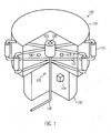
- Fig. 1 is a schematic representation of a blow molding machine according to the invention
- a blow molding machine 100 according to the invention is shown. This has a standing part 102 and a rotating part 101. On the rotating part 101 of the blow molding machine 100, the blow molds 110 are arranged. During the blow molding process, on the one hand, it is necessary to temper the molds, so that the plastic entered a corresponding Can take shape and properties. On the other hand, it is then necessary to cool the blow molds as quickly as possible, so that, for example, a change of shape can be carried out. To ensure this, a temperature control unit 120 is provided. It can be arranged according to the invention within both the stationary and the rotating part of the blow molding machine 102 and 101, respectively.
- heating and cooling elements 105 and 106 are provided. They serve to heat or cool the medium, while it is supplied to or removed from the blow molds and their receiving device through the lines 107.
- the heating element 105 or cooling elements 106 are shown here only schematically, since there are various possibilities of the embodiments. For example, it can be provided that the heating and cooling elements 105 and 106 are arranged concentrically around the supply and discharge lines 107 and can thus perform heating or cooling over the entire route. On the other hand, it can also be provided that 100 heating and cooling elements 105 and 106 are arranged in the stationary part 102 of the blow molding machine.
- the arrangement of the components can be carried out so that a part of the system is kept at process temperature, at the same time the blow molds are cooled down quickly, for example to perform a mold change. Subsequently, the blow molds are tempered again to process temperature. This arrangement reduces the restart time of the machine.
- the design of the heating elements 105 and cooling elements 106 can be very different.
- the heating element 105 may be provided, for example, as a microwave source
- the cooling element may be provided such that initially a control valve is provided which conveys the warm water from the temperature control in a return.
- cold water can be supplied to the system, for example, by a check valve, whereby the entire medium temperature drops.
- a secondary heating element 108 may be provided. It may, for example, be arranged on the cooling water supply 103 or already on the supply line 130. It serves to heat the medium to a temperature at which the formation of condensed water can be reduced or preferably avoided.
- the heating element and / or the cooling element 105 or 106 can also be arranged in the stationary part 102 of the blow molding machine 100.
- the cooling element 106 comprises a valve for discharging hot water and a valve for introducing cold water, it can also be provided that parts of the cooling element 106 are arranged in the standing part 102 and other parts in the rotating part 101 of the blow molding machine 100.
- the arrangement of the secondary heating element 108 can also be changed.
- the secondary heating element may also be arranged at the lower end or in the lateral, rearward region of the stationary part 102 of the blow molding machine 100 in order to increase the medium temperature of the cooling water from the supply line 130 already.
- the cooling water supply 103 likewise in the stationary part 102 of the blow molding machine 100. In this case, one is as in Fig. 1 shown central arrangement of the cooling water supply 103 is not necessary and it could be mounted in principle in any position in the standing part 102 of the blow molding machine 100. A non-central arrangement would also be possible in the rotating part 101 of the blow molding machine 100.
Landscapes
- Engineering & Computer Science (AREA)
- Mechanical Engineering (AREA)
- Manufacturing & Machinery (AREA)
- Physics & Mathematics (AREA)
- Thermal Sciences (AREA)
- Blow-Moulding Or Thermoforming Of Plastics Or The Like (AREA)
- Moulds For Moulding Plastics Or The Like (AREA)
Description
- Die Erfindung betrifft eine Blasformmaschine mit einem Temperiergerät und ein entsprechendes Verfahren zum Temperieren von Blasformen und deren Aufnahmevorrichtung (Formträger) einer Blasformmaschine.
- Aus dem Stand der Technik sind Blasformmaschinen bekannt. Da insbesondere die Blasformen gekühlt und die Vorformlinge erwärmt werden müssen, ist der Gebrauch von Heizstationen und Kühlkörpern im Zusammenhang mit Blasmaschinen z.B. aus der
DE 20 309 576 U1 bekannt. Diese beschreibt eine Blasmaschine zum Herstellen von Hohlkörpern aus thermoplastischem Kunststoff, wobei eine Heizstation zum Erwärmen der Vorformlinge und Kühlmittel zum Kühlen der Blasform vorgesehen sind. Das Kühlmittel wird über ein Kühlaggregat bereitgestellt, das, im Vergleich zu den Abmessungen der Blasmaschine, in großer Entfernung von der Blasmaschine angeordnet ist. Das bewirkt jedoch einen gewissen Platzaufwand und führt zu Leistungsverlusten während des Transports der Kühlflüssigkeit. - Weiterhin zeigt die
DE 10 2010 028 253 A1 eine Blasmaschine mit einem zentralen Temperiergerät, das entweder im drehenden oder im stehenden Teil der Maschine angeordnet sein kann. Es kann weiterhin außerhalb der Blasformmaschine angeordnet sein. Aufgrund langer Leitungswege des Kühlmediums zu den einzelnen Blasformen ist eine genaue Einstellung der Mediumstemperatur jedoch schwierig. - Ferner offenbart die
DE 101 42 988 A1 eine Verteilungseinrichtung zum Verteilen von Kühlmedien an einzelne Blasstationen einer Blasformmaschine. Aufgrund der Anordnung des Temperiergeräts in einer Entfernung zur eigentlichen Blasmaschine ist es auch hier schwierig, eine genaue Temperierung des Mediums auf eine gewünschte Temperatur zu erreichen. - Der Erfindung liegt die Aufgabe zugrunde, Blasmaschinen hinsichtlich der Temperierung ihrer Blasformen zu verbessern.
- Die Aufgabe wird erfindungsgemäß durch die Blasformmaschine nach Anspruch 1 und das Verfahren nach Anspruch 6 gelöst.
- Die Unteransprüche beinhalten zweckmäßige Ausgestaltungen der Erfindung.
- Die Erfindung zeichnet sich dadurch aus, dass die Blasformmaschine, die einen stehenden und einen drehenden Teil mit Blasformen sowie ein Temperiergerät zur Temperierung der Blasformen umfasst, dadurch gekennzeichnet ist, dass das Temperiergerät innerhalb der Blasformmaschine angeordnet ist. Dadurch wird zum Einen erreicht, dass eine erhebliche Platzersparnis realisiert werden kann, da beispielsweise keine Leitungen außerhalb der Blasformmaschine zum Transport der Kühlflüssigkeit vom Temperiergerät zu den einzelnen Blasformen nötig sind. Zum Anderen kann durch die Anordnung des Temperiergeräts direkt innerhalb der Blasformmaschine eine Veränderung der Temperatur des Mediums während des Transports zur Blasform effektiv reduziert oder sogar vermieden werden. Dadurch werden aufwändige Isolierungen der entsprechenden Leitungen und Zwischenstationen zum Wiederaufheizen oder Abkühlen zum Teil oder vollständig unnötig.
- In einer Ausführungsform ist die Blasformmaschine dadurch gekennzeichnet, dass das Temperiergerät ein Heizelement, ein Kühlelement, eine Steuereinheit, die in die Maschinensteuerung integriert sein kann, eine Wasserpumpe, eine Kühlwasserversorgung und Verbindungen des Temperiergeräts zu einer, vorzugsweise allen Blasformen der Blasformmaschine umfasst. Durch die Anordnung sämtlicher für die Temperierung und die Steuerung der Temperierung notwendigen Komponenten innerhalb der Blasformmaschine kann die Temperierung nicht nur ökonomischer und platzsparender erfolgen, sondern insbesondere durch das Anordnen der Steuereinheit innerhalb der Blasformmaschine brauchen entsprechende Verbindungen (beispielsweise Kabel und Rohr, bzw. Schlauchleitungen) nicht mehr durch die Produktionshalle, in der die Blasformmaschine angeordnet ist, verlegt werden und somit können Risiken wie beispielsweise die Beschädigung entsprechender Leitungen vermieden werden.
- In einer Ausführungsform ist die Blasformmaschine dadurch gekennzeichnet, dass die Steuereinheit geeignet ist, die Temperatur des in dem Temperiergerät verwendeten Mediums so zu steuern, dass die Bildung von Kondenswasser reduziert, vorzugsweise vermieden werden kann. Die Vermeidung der Bildung von Kondenswasser kann erheblich die Standzeit der Blasformmaschine verbessern, da beispielsweise durch Kondenswasser an Verbindungsrohren Rost oder andere Materialbeeinträchtigungen die Funktionsfähigkeit der Blasformmaschine stören können. Des Weiteren wird die Kontaminierung durch Mikroorganismen erschwert, da die nötige Feuchtigkeit an den Oberflächen fehlt.
- In einer weiteren Ausführungsform ist zumindest eines von dem Heizelement, dem Kühlelement, der Steuereinheit, der Kühlwasserversorgung, der Wasserpumpe, den Verbindungen und der Steuereinheit im stehenden Teil der Blasformmaschine vorgesehen und die übrigen im drehenden Teil der Blasformmaschine. Eine entsprechende Aufteilung der Komponenten kann vorteilhaft sein, da beispielsweise ein Vorsehen des Kühlelements und der Verbindungen im drehenden Teil der Blasformmaschine flexible Verbindungen zwischen dem Kühlelement und den Verbindungen zu den Blasformen überflüssig macht.
- In einer Ausführungsform zeichnet sich die Blasformmaschine dadurch aus, dass ein Sekundärheizelement im Temperiergerät vorgesehen ist, das geeignet ist, die Temperatur des verwendeten Mediums auf eine höhere Temperatur anzuheben. Dieses Sekundärheizelement wird beispielsweise genutzt, um Blasformen schnell auf Einsatztemperatur zu bringen.
- Unter Verwendung beispielsweise dieser Vorrichtung lässt sich ein Verfahren zum Temperieren von Blasformen einer Blasformmaschine verwirklichen, wobei das Verfahren dadurch gekennzeichnet ist, dass das Temperieren der Blasformen durch ein durch das in der Blasmaschine angeordnete Temperiergerät befördertes Medium vorgenommen wird. Mit Hilfe dieses entsprechenden Verfahrens lassen sich erhebliche Platzersparnisse und insbesondere Energieersparnisse erreichen.
- In einer Ausführungsform ist das Verfahren dadurch gekennzeichnet, dass durch ein im Temperiergerät angeordnetes Sekundärheizelement die Temperatur des Mediums auf eine Temperatur angehoben wird, bei der die Bildung von Kondenswasser reduziert, vorzugsweise vermieden wird, bevor die Blasformmaschine in Betrieb genommen wird. Dadurch kann erreicht werden, dass das Medium bereits vor Inbetriebnahme der Blasformmaschine auf einer geeigneten Temperatur ist und dementsprechend kann eine verkürzte Anlaufzeit der Blasformmaschine realisiert werden.
- In einer weiteren Ausführungsform ist das Verfahren dadurch gekennzeichnet, dass zur Stabilisierung der Temperatur des Mediums auf eine Solltemperatur Kaltwasser zugegeben wird. Verändert sich die Temperatur des Mediums, beispielsweise durch Wärmeaufnahme durch die Blasform, kann durch das Kaltwasser erreicht werden, dass es schnell zu einer Reduktion der Temperatur auf die gewünschte Solltemperatur kommt.
- In einer weiteren Ausführungsform wird das Kaltwasser in Abhängigkeit von der Temperatur der Blasform zugegeben. So lässt sich eine gezielte Steuerung der Kaltwasserzufuhr erreichen und eine Stabilisierung der Solltemperatur ist angepasst an die momentanen Abläufe in der Blasformmaschine.
-
Fig. 1 ist eine schematische Darstellung einer erfindungsgemäßen Blasformmaschine - In
Fig. 1 ist eine erfindungsgemäße Blasformmaschine 100 dargestellt. Diese verfügt über einen stehenden Teil 102 und einen sich drehenden Teil 101. Am drehenden Teil 101 der Blasformmaschine 100 sind die Blasformen 110 angeordnet. Während des Blasformverfahrens ist es zum Einen nötig, die Formen zu temperieren, so dass der eingegebene Kunststoff eine entsprechende Form und Eigenschaften annehmen kann. Andererseits ist es nötig, anschließend die Blasformen möglichst schnell zu kühlen, so dass z.B. ein Formwechsel durchgeführt werden kann. Um das zu gewährleisten, ist ein Temperiergerät 120 vorgesehen. Es kann erfindungsgemäß innerhalb sowohl der stehenden als auch des drehenden Teils der Blasformmaschine 102 bzw. 101 angeordnet sein. Es umfasst eine Kühlwasserversorgung 103, die über eine Zuleitung 130 mit einer externen Wasserversorgung verbunden sein kann. Ferner sind Heiz- und Kühlelemente 105 bzw. 106 vorgesehen. Sie dienen der Erwärmung bzw. Abkühlung des Mediums, während es durch die Leitungen 107 den Blasformen und deren Aufnahmevorrichtung zu- bzw. abgeführt wird. Die Heizelement 105 bzw. Kühlelemente 106 sind hier nur schematisch dargestellt, da es diverse Möglichkeiten der Ausführungen gibt. So kann beispielsweise vorgesehen sein, dass die Heiz- und Kühlelemente 105 bzw. 106 konzentrisch um die Zu- bzw. Ableitungen 107 angeordnet sind und so auf der gesamten Strecke eine Erwärmung bzw. Abkühlung vornehmen können. Andererseits kann auch vorgesehen sein, dass im stehenden Teil 102 der Blasformmaschine 100 Heiz- und Kühlelemente 105 bzw. 106 angeordnet sind. Die Anordnung der Komponenten kann so erfolgen, dass ein Teil des Systems auf Prozesstemperatur gehalten wird, wobei gleichzeitig die Blasformen schnell heruntergekühlt werden um z.B. einen Formenwechsel durchzuführen. Anschließend werden die Blasformen wieder auf Prozesstemperatur temperiert. Diese Anordnung verringert die Wiederanfahrzeit der Maschine. Auch die Ausgestaltung der Heizelemente 105 bzw. Kühlelemente 106 kann sehr unterschiedlich sein. So kann das Heizelement 105 beispielsweise als Mikrowellenquelle vorgesehen sein, wohingegen das Kühlelement derart vorgesehen sein kann, dass zunächst ein Regelventil vorgesehen ist, das das warme Wasser aus dem Temperierkreislauf in einen Rücklauf befördert. Gleichzeitig kann beispielsweise durch ein Rückschlagventil Kaltwasser dem System zugeführt werden, womit die gesamte Mediumstemperatur sinkt. - Zusätzlich kann ein Sekundärheizelement 108 vorgesehen sein. Es kann beispielsweise an der Kühlwasserversorgung 103 oder bereits an der Zuleitung 130 angeordnet sein. Es dient der Erwärmung des Mediums auf eine Temperatur, bei der die Bildung von Kondenswasser reduziert bzw. vorzugsweise vermieden werden kann.
- Die in
Fig. 1 dargestellte Anordnung der Bestandteile des Temperiergeräts 120 ist keinesfalls zwingend. Wie bereits erwähnt, kann beispielsweise das Heizelement und/oder das Kühlelement 105 bzw. 106 auch im stehenden Teil 102 der Blasformmaschine 100 angeordnet sein. Umfasst das Kühlelement 106 ein Ventil zur Ausleitung von Warmwasser und ein Ventil zum Einleiten von Kaltwasser, so kann auch vorgesehen sein, dass Teile des Kühlelements 106 im stehenden Teil 102 und andere Teile im sich drehenden Teil 101 der Blasformmaschine 100 angeordnet sind. Auch die Anordnung des Sekundärheizelements 108 kann verändert werden. - So kann das Sekundärheizelement beispielsweise auch am unteren Ende oder im seitlichen, rückwärtigen Bereich des stehenden Teils 102 der Blasformmaschine 100 angeordnet sein, um die Mediumstemperatur des Kühlwassers aus der Zuleitung 130 bereits zu erhöhen. Ebenso ist denkbar, die Kühlwasserversorgung 103 ebenfalls in dem stehenden Teil 102 der Blasformmaschine 100 anzuordnen. In diesem Fall ist eine, wie in
Fig. 1 dargestellte zentrale Anordnung der Kühlwasserversorgung 103 nicht notwendig und sie könnte prinzipiell in beliebiger Position im stehenden Teil 102 der Blasformmaschine 100 angebracht sein. Eine nicht zentrale Anordnung wäre auch im drehenden Teil 101 der Blasformmaschine 100 möglich.
Claims (10)
- Blasformmaschine (100) mit einem stehenden (102) und einem drehenden Teil (101) mit Blasformen (110), umfassend ein Temperiergerät (120) zur Temperierung der Blasformen (110) mit Hilfe eines Mediums, dadurch gekennzeichnet, dass das Temperiergerät (120) innerhalb der Blasformmaschine (100) angeordnet ist, wobei das Temperiergerät (120) ein Heizelement (105), ein Kühlelement (106), eine Pumpe, eine Steuereinheit (104), eine Kühlwasserversorgung (103) und Verbindungen (107) des Temperiergeräts (120) zu einer, vorzugsweise allen Blasformen (110) der Blasformmaschine (100) umfasst.
- Blasformmaschine (100) nach Anspruch 1, dadurch gekennzeichnet, dass die Steuereinheit (120) in eine Maschinensteuerung integriert ist.
- Blasformmaschine (100) nach Anspruch 1, dadurch gekennzeichnet, dass die Steuereinheit (104) geeignet ist, die Temperatur des in dem Temperiergerät (120) verwendeten Mediums so zu steuern, dass die Bildung von Kondenswasser reduziert, vorzugsweise vermieden werden kann.
- Blasformmaschine (100) nach einem der Ansprüche 1 bis 3, dadurch gekennzeichnet, dass die Steuereinheit (120) ein oder mehrere Prozesskreisläufe regeln kann.
- Blasformmaschine nach einem der Ansprüche 1 bis 4, dadurch gekennzeichnet, dass wenigstens eines von dem Heizelement (105), dem Kühlelement (106), der Steuereinheit (104), der Kühlwasserversorgung (103), den Verbindungen (107) im stehenden Teil (102) der Blasformmaschine (100) vorgesehen ist und die übrigen im drehenden Teil (101) der Blasformmaschine (100) vorgesehen sind.
- Blasformmaschine (100) nach einem der Ansprüche 1 bis 5, dadurch gekennzeichnet, dass ein Sekundärheizelement (108) im Temperiergerät (120) vorgesehen ist, das geeignet ist, die Temperatur des verwendeten Mediums auf eine Temperatur anzuheben, bei der die Bildung von Kondenswasser reduziert, vorzugsweise vermieden werden kann.
- Verfahren zum Temperieren von Blasformen (110) einer Blasformmaschine (100) mit Hilfe eines in der Blasformmaschine (100) angeordneten Temperiergeräts (120) gemäß einem der Ansprüche 1 bis 6, wobei das Temperieren der Blasformen (110) durch ein durch das Temperiergerät (120) befördertes Medium vorgenommen wird.
- Verfahren zum Temperieren von Blasformen (110) nach Anspruch 7, dadurch gekennzeichnet, dass durch ein im Temperiergerät (120) angeordnetes Sekundärheizelement (108) die Temperatur des Mediums auf eine Temperatur angehoben wird, bei der die Bildung von Kondenswasser reduziert, vorzugsweise vermieden wird, bevor die Blasformmaschine (100) in Betrieb genommen wird.
- Verfahren zum Temperieren von Blasenformen (110) nach Anspruch 7 oder 8, dadurch gekennzeichnet, dass zur Stabilisierung der Temperatur des Mediums auf eine Solltemperatur Kaltwasser zugegeben wird
- Verfahren zum Temperieren von Blasformen (110) nach Anspruch 9, dadurch gekennzeichnet, dass Kaltwasser in Abhängigkeit von der Temperatur der Blasformen (110) zugegeben wird.
Applications Claiming Priority (1)
| Application Number | Priority Date | Filing Date | Title |
|---|---|---|---|
| DE102012212773.9A DE102012212773A1 (de) | 2012-07-20 | 2012-07-20 | Blasformmaschine mit innen liegendem temperiergerät |
Publications (2)
| Publication Number | Publication Date |
|---|---|
| EP2687351A1 EP2687351A1 (de) | 2014-01-22 |
| EP2687351B1 true EP2687351B1 (de) | 2015-09-02 |
Family
ID=48655970
Family Applications (1)
| Application Number | Title | Priority Date | Filing Date |
|---|---|---|---|
| EP13171944.5A Active EP2687351B1 (de) | 2012-07-20 | 2013-06-14 | Blasformmaschine mit innen liegendem Temperiergerät |
Country Status (4)
| Country | Link |
|---|---|
| US (1) | US10173382B2 (de) |
| EP (1) | EP2687351B1 (de) |
| CN (1) | CN103568303B (de) |
| DE (1) | DE102012212773A1 (de) |
Families Citing this family (1)
| Publication number | Priority date | Publication date | Assignee | Title |
|---|---|---|---|---|
| DE102018117849A1 (de) * | 2018-07-24 | 2020-01-30 | Krones Ag | Verfahren und Vorrichtung zum Umformen von Kunststoffvorformlingen zu Kunststoffbehältnissen mit Vortemperierung von Blasformen |
Family Cites Families (13)
| Publication number | Priority date | Publication date | Assignee | Title |
|---|---|---|---|---|
| DE1014298B (de) | 1954-10-29 | 1957-08-22 | Maschf Augsburg Nuernberg Ag | Kopierwerk fuer die Steuerung von Hebezeugen, insbesondere Aufzugsanlagen |
| DE19727278A1 (de) * | 1997-02-17 | 1999-01-07 | Kronseder Maschf Krones | Blasformmaschine |
| DE10142988A1 (de) * | 2001-09-01 | 2003-03-20 | Sig Corpoplast Gmbh & Co Kg | Vorrichtung zur Verteilung von Flüssigkeiten |
| DE20305015U1 (de) | 2003-03-28 | 2003-07-31 | KRONES AG, 93073 Neutraubling | Blasmaschine |
| DE10357247A1 (de) * | 2003-12-05 | 2005-07-21 | Sig Technology Ltd. | Verfahren und Vorrichtung zur Bearbeitung von Werkstücken |
| DE102008012757A1 (de) | 2008-03-05 | 2009-09-10 | Krones Ag | Vorrichtung zum Erzeugen von Kunststoffbehältnissen |
| DE102008029531A1 (de) * | 2008-06-21 | 2009-12-24 | Krones Ag | Verfahren und Vorrichtung zum Einsetzen eines Vorformlings in und zur Entnahme einer Flasche aus einer Blasmaschine |
| DE102008047891A1 (de) * | 2008-09-18 | 2010-03-25 | Krones Ag | Temperierte Reckstange |
| DE102009015519A1 (de) * | 2009-04-02 | 2010-10-07 | Krones Ag | Vorrichtung zum Umformen von Kunststoffvorformlingen mit Heizeinrichtung |
| DE102009031154A1 (de) * | 2009-06-30 | 2011-01-05 | Krones Ag | Verfahren zum Umrüsten einer Blasmaschine und Blasmaschine |
| DE102010028253A1 (de) * | 2010-04-27 | 2011-10-27 | Krones Ag | Blasmaschine |
| DE102010032965A1 (de) * | 2010-07-30 | 2012-02-02 | Krones Aktiengesellschaft | Streckblasmaschine mit integriertem Kompressor |
| DE102011080833A1 (de) * | 2011-08-11 | 2013-02-14 | Krones Aktiengesellschaft | Vorrichtung und Verfahren zum Blasformen von Behältern |
-
2012
- 2012-07-20 DE DE102012212773.9A patent/DE102012212773A1/de not_active Withdrawn
-
2013
- 2013-06-14 EP EP13171944.5A patent/EP2687351B1/de active Active
- 2013-07-19 US US13/946,671 patent/US10173382B2/en active Active
- 2013-07-19 CN CN201310306191.XA patent/CN103568303B/zh active Active
Also Published As
| Publication number | Publication date |
|---|---|
| CN103568303B (zh) | 2016-08-10 |
| EP2687351A1 (de) | 2014-01-22 |
| CN103568303A (zh) | 2014-02-12 |
| DE102012212773A1 (de) | 2014-01-23 |
| US10173382B2 (en) | 2019-01-08 |
| US20140021657A1 (en) | 2014-01-23 |
Similar Documents
| Publication | Publication Date | Title |
|---|---|---|
| EP2208606A2 (de) | Streckblasmaschine mit beheizbarer Blasform | |
| DE102010028253A1 (de) | Blasmaschine | |
| EP2881233A1 (de) | Blasformmaschine mit erwärmbarer Kühlmittelzuführung | |
| EP2269910A2 (de) | Leimaufbereitungsvorrichtung | |
| EP2556944A2 (de) | Vorrichtung und Verfahren zum Blasformen von Behältern | |
| EP2532247A1 (de) | Produktvorwärmung mit Wärmepumpe | |
| EP2781335B1 (de) | Vorrichtung zum Steuern eines Temperiergeräts einer Blasform-Maschine und Verfahren zum Steuern eines Temperiergeräts einer Blasform-Maschine | |
| EP2687351B1 (de) | Blasformmaschine mit innen liegendem Temperiergerät | |
| EP2722151B1 (de) | Verfahren und Blasformmaschine mit Reinraum und Trocknungseinrichtung für Luftzuführung | |
| DE102009057891A1 (de) | Blasformmaschine mit Kühleinrichtung | |
| DE102014012706B4 (de) | Vorrichtung zur Klimatisierung eines Fahrzeuginnenraums | |
| WO2015165430A1 (de) | Heizeinrichtung für reifenvulkanisiermaschinen und verfaren zur beheizung eines reifenrohlings in einer reifenvulkanisiermaschine | |
| EP3458247A1 (de) | Vorrichtung zum erwärmen von vorformlingen mit mitfahrendem topstrahler | |
| DE102010062260A1 (de) | Temperierbares Formwerkzeugelement | |
| WO2015035980A1 (de) | Vorrichtung zum wechsel von spritzgussformen | |
| EP2656993B1 (de) | Formwerzeug und Verfahren zur Herstellung eines Faserverbundbauteils | |
| DE102013108998B4 (de) | Temperier- und Wärmerückgewinnungssystem für wenigstens eine mit einem Fluid temperierbare Maschine und Verfahren zum Betreiben eines Temperier- und Wärmerückgewinnungssystem | |
| EP2107323B1 (de) | Vorrichtung zur Erzeugung von Kalt- und Warmwasser | |
| EP2899480B1 (de) | Kühlsystem für Behälterbehandlungsanlagen | |
| DE102008028218B4 (de) | Verfahren zum Abkühlen von extrudierten Werkstücken aus Kunststoff | |
| EP3793803B1 (de) | Verfahren und vorrichtung zum umformen von kunststoffvorformlingen zu kunststoffbehältnissen mit vortemperierung von blasformen | |
| WO2019025550A1 (de) | Vorrichtung und verfahren zum umformen von kunststoffvorformlingen zu kunststoffbehältnissen mit bodenformtemperierung | |
| DE102017123753A1 (de) | Temperiervorrichtung für das Temperieren eines Elektrofahrzeugs | |
| DE202005013395U1 (de) | Kühlsystem zum Kühlen von Prozesswasser | |
| DE10329493B3 (de) | Zufuhrvorrichtung für ein Temperiermittel zur Versorgung von Temperiermittelkanälen |
Legal Events
| Date | Code | Title | Description |
|---|---|---|---|
| PUAI | Public reference made under article 153(3) epc to a published international application that has entered the european phase |
Free format text: ORIGINAL CODE: 0009012 |
|
| AK | Designated contracting states |
Kind code of ref document: A1 Designated state(s): AL AT BE BG CH CY CZ DE DK EE ES FI FR GB GR HR HU IE IS IT LI LT LU LV MC MK MT NL NO PL PT RO RS SE SI SK SM TR |
|
| AX | Request for extension of the european patent |
Extension state: BA ME |
|
| 17P | Request for examination filed |
Effective date: 20140507 |
|
| RBV | Designated contracting states (corrected) |
Designated state(s): AL AT BE BG CH CY CZ DE DK EE ES FI FR GB GR HR HU IE IS IT LI LT LU LV MC MK MT NL NO PL PT RO RS SE SI SK SM TR |
|
| GRAP | Despatch of communication of intention to grant a patent |
Free format text: ORIGINAL CODE: EPIDOSNIGR1 |
|
| INTG | Intention to grant announced |
Effective date: 20150311 |
|
| GRAS | Grant fee paid |
Free format text: ORIGINAL CODE: EPIDOSNIGR3 |
|
| GRAA | (expected) grant |
Free format text: ORIGINAL CODE: 0009210 |
|
| AK | Designated contracting states |
Kind code of ref document: B1 Designated state(s): AL AT BE BG CH CY CZ DE DK EE ES FI FR GB GR HR HU IE IS IT LI LT LU LV MC MK MT NL NO PL PT RO RS SE SI SK SM TR |
|
| REG | Reference to a national code |
Ref country code: GB Ref legal event code: FG4D Free format text: NOT ENGLISH |
|
| REG | Reference to a national code |
Ref country code: AT Ref legal event code: REF Ref document number: 746271 Country of ref document: AT Kind code of ref document: T Effective date: 20150915 Ref country code: CH Ref legal event code: EP |
|
| REG | Reference to a national code |
Ref country code: IE Ref legal event code: FG4D Free format text: LANGUAGE OF EP DOCUMENT: GERMAN |
|
| REG | Reference to a national code |
Ref country code: DE Ref legal event code: R096 Ref document number: 502013001082 Country of ref document: DE |
|
| PG25 | Lapsed in a contracting state [announced via postgrant information from national office to epo] |
Ref country code: NO Free format text: LAPSE BECAUSE OF FAILURE TO SUBMIT A TRANSLATION OF THE DESCRIPTION OR TO PAY THE FEE WITHIN THE PRESCRIBED TIME-LIMIT Effective date: 20151202 Ref country code: LT Free format text: LAPSE BECAUSE OF FAILURE TO SUBMIT A TRANSLATION OF THE DESCRIPTION OR TO PAY THE FEE WITHIN THE PRESCRIBED TIME-LIMIT Effective date: 20150902 Ref country code: FI Free format text: LAPSE BECAUSE OF FAILURE TO SUBMIT A TRANSLATION OF THE DESCRIPTION OR TO PAY THE FEE WITHIN THE PRESCRIBED TIME-LIMIT Effective date: 20150902 Ref country code: GR Free format text: LAPSE BECAUSE OF FAILURE TO SUBMIT A TRANSLATION OF THE DESCRIPTION OR TO PAY THE FEE WITHIN THE PRESCRIBED TIME-LIMIT Effective date: 20151203 Ref country code: LV Free format text: LAPSE BECAUSE OF FAILURE TO SUBMIT A TRANSLATION OF THE DESCRIPTION OR TO PAY THE FEE WITHIN THE PRESCRIBED TIME-LIMIT Effective date: 20150902 |
|
| REG | Reference to a national code |
Ref country code: LT Ref legal event code: MG4D Ref country code: NL Ref legal event code: MP Effective date: 20150902 |
|
| PG25 | Lapsed in a contracting state [announced via postgrant information from national office to epo] |
Ref country code: ES Free format text: LAPSE BECAUSE OF FAILURE TO SUBMIT A TRANSLATION OF THE DESCRIPTION OR TO PAY THE FEE WITHIN THE PRESCRIBED TIME-LIMIT Effective date: 20150902 Ref country code: SE Free format text: LAPSE BECAUSE OF FAILURE TO SUBMIT A TRANSLATION OF THE DESCRIPTION OR TO PAY THE FEE WITHIN THE PRESCRIBED TIME-LIMIT Effective date: 20150902 Ref country code: RS Free format text: LAPSE BECAUSE OF FAILURE TO SUBMIT A TRANSLATION OF THE DESCRIPTION OR TO PAY THE FEE WITHIN THE PRESCRIBED TIME-LIMIT Effective date: 20150902 Ref country code: PL Free format text: LAPSE BECAUSE OF FAILURE TO SUBMIT A TRANSLATION OF THE DESCRIPTION OR TO PAY THE FEE WITHIN THE PRESCRIBED TIME-LIMIT Effective date: 20150902 |
|
| PG25 | Lapsed in a contracting state [announced via postgrant information from national office to epo] |
Ref country code: IS Free format text: LAPSE BECAUSE OF FAILURE TO SUBMIT A TRANSLATION OF THE DESCRIPTION OR TO PAY THE FEE WITHIN THE PRESCRIBED TIME-LIMIT Effective date: 20160102 Ref country code: EE Free format text: LAPSE BECAUSE OF FAILURE TO SUBMIT A TRANSLATION OF THE DESCRIPTION OR TO PAY THE FEE WITHIN THE PRESCRIBED TIME-LIMIT Effective date: 20150902 Ref country code: CZ Free format text: LAPSE BECAUSE OF FAILURE TO SUBMIT A TRANSLATION OF THE DESCRIPTION OR TO PAY THE FEE WITHIN THE PRESCRIBED TIME-LIMIT Effective date: 20150902 Ref country code: NL Free format text: LAPSE BECAUSE OF FAILURE TO SUBMIT A TRANSLATION OF THE DESCRIPTION OR TO PAY THE FEE WITHIN THE PRESCRIBED TIME-LIMIT Effective date: 20150902 Ref country code: SK Free format text: LAPSE BECAUSE OF FAILURE TO SUBMIT A TRANSLATION OF THE DESCRIPTION OR TO PAY THE FEE WITHIN THE PRESCRIBED TIME-LIMIT Effective date: 20150902 |
|
| REG | Reference to a national code |
Ref country code: FR Ref legal event code: PLFP Year of fee payment: 4 |
|
| PG25 | Lapsed in a contracting state [announced via postgrant information from national office to epo] |
Ref country code: PT Free format text: LAPSE BECAUSE OF FAILURE TO SUBMIT A TRANSLATION OF THE DESCRIPTION OR TO PAY THE FEE WITHIN THE PRESCRIBED TIME-LIMIT Effective date: 20160104 Ref country code: RO Free format text: LAPSE BECAUSE OF FAILURE TO SUBMIT A TRANSLATION OF THE DESCRIPTION OR TO PAY THE FEE WITHIN THE PRESCRIBED TIME-LIMIT Effective date: 20150902 |
|
| REG | Reference to a national code |
Ref country code: DE Ref legal event code: R097 Ref document number: 502013001082 Country of ref document: DE |
|
| PLBE | No opposition filed within time limit |
Free format text: ORIGINAL CODE: 0009261 |
|
| STAA | Information on the status of an ep patent application or granted ep patent |
Free format text: STATUS: NO OPPOSITION FILED WITHIN TIME LIMIT |
|
| 26N | No opposition filed |
Effective date: 20160603 |
|
| PG25 | Lapsed in a contracting state [announced via postgrant information from national office to epo] |
Ref country code: DK Free format text: LAPSE BECAUSE OF FAILURE TO SUBMIT A TRANSLATION OF THE DESCRIPTION OR TO PAY THE FEE WITHIN THE PRESCRIBED TIME-LIMIT Effective date: 20150902 Ref country code: SI Free format text: LAPSE BECAUSE OF FAILURE TO SUBMIT A TRANSLATION OF THE DESCRIPTION OR TO PAY THE FEE WITHIN THE PRESCRIBED TIME-LIMIT Effective date: 20150902 |
|
| PG25 | Lapsed in a contracting state [announced via postgrant information from national office to epo] |
Ref country code: BE Free format text: LAPSE BECAUSE OF NON-PAYMENT OF DUE FEES Effective date: 20160630 |
|
| PG25 | Lapsed in a contracting state [announced via postgrant information from national office to epo] |
Ref country code: MC Free format text: LAPSE BECAUSE OF FAILURE TO SUBMIT A TRANSLATION OF THE DESCRIPTION OR TO PAY THE FEE WITHIN THE PRESCRIBED TIME-LIMIT Effective date: 20150902 |
|
| REG | Reference to a national code |
Ref country code: CH Ref legal event code: PL |
|
| REG | Reference to a national code |
Ref country code: IE Ref legal event code: MM4A |
|
| PG25 | Lapsed in a contracting state [announced via postgrant information from national office to epo] |
Ref country code: CH Free format text: LAPSE BECAUSE OF NON-PAYMENT OF DUE FEES Effective date: 20160630 Ref country code: LI Free format text: LAPSE BECAUSE OF NON-PAYMENT OF DUE FEES Effective date: 20160630 |
|
| REG | Reference to a national code |
Ref country code: FR Ref legal event code: PLFP Year of fee payment: 5 |
|
| PG25 | Lapsed in a contracting state [announced via postgrant information from national office to epo] |
Ref country code: IE Free format text: LAPSE BECAUSE OF NON-PAYMENT OF DUE FEES Effective date: 20160614 |
|
| GBPC | Gb: european patent ceased through non-payment of renewal fee |
Effective date: 20170614 |
|
| PG25 | Lapsed in a contracting state [announced via postgrant information from national office to epo] |
Ref country code: GB Free format text: LAPSE BECAUSE OF NON-PAYMENT OF DUE FEES Effective date: 20170614 |
|
| REG | Reference to a national code |
Ref country code: FR Ref legal event code: PLFP Year of fee payment: 6 |
|
| PG25 | Lapsed in a contracting state [announced via postgrant information from national office to epo] |
Ref country code: SM Free format text: LAPSE BECAUSE OF FAILURE TO SUBMIT A TRANSLATION OF THE DESCRIPTION OR TO PAY THE FEE WITHIN THE PRESCRIBED TIME-LIMIT Effective date: 20150902 Ref country code: CY Free format text: LAPSE BECAUSE OF FAILURE TO SUBMIT A TRANSLATION OF THE DESCRIPTION OR TO PAY THE FEE WITHIN THE PRESCRIBED TIME-LIMIT Effective date: 20150902 Ref country code: HU Free format text: LAPSE BECAUSE OF FAILURE TO SUBMIT A TRANSLATION OF THE DESCRIPTION OR TO PAY THE FEE WITHIN THE PRESCRIBED TIME-LIMIT; INVALID AB INITIO Effective date: 20130614 |
|
| PG25 | Lapsed in a contracting state [announced via postgrant information from national office to epo] |
Ref country code: HR Free format text: LAPSE BECAUSE OF FAILURE TO SUBMIT A TRANSLATION OF THE DESCRIPTION OR TO PAY THE FEE WITHIN THE PRESCRIBED TIME-LIMIT Effective date: 20150902 Ref country code: MK Free format text: LAPSE BECAUSE OF FAILURE TO SUBMIT A TRANSLATION OF THE DESCRIPTION OR TO PAY THE FEE WITHIN THE PRESCRIBED TIME-LIMIT Effective date: 20150902 Ref country code: LU Free format text: LAPSE BECAUSE OF NON-PAYMENT OF DUE FEES Effective date: 20160614 Ref country code: TR Free format text: LAPSE BECAUSE OF FAILURE TO SUBMIT A TRANSLATION OF THE DESCRIPTION OR TO PAY THE FEE WITHIN THE PRESCRIBED TIME-LIMIT Effective date: 20150902 Ref country code: MT Free format text: LAPSE BECAUSE OF FAILURE TO SUBMIT A TRANSLATION OF THE DESCRIPTION OR TO PAY THE FEE WITHIN THE PRESCRIBED TIME-LIMIT Effective date: 20150902 |
|
| PG25 | Lapsed in a contracting state [announced via postgrant information from national office to epo] |
Ref country code: BG Free format text: LAPSE BECAUSE OF FAILURE TO SUBMIT A TRANSLATION OF THE DESCRIPTION OR TO PAY THE FEE WITHIN THE PRESCRIBED TIME-LIMIT Effective date: 20150902 |
|
| PG25 | Lapsed in a contracting state [announced via postgrant information from national office to epo] |
Ref country code: AL Free format text: LAPSE BECAUSE OF FAILURE TO SUBMIT A TRANSLATION OF THE DESCRIPTION OR TO PAY THE FEE WITHIN THE PRESCRIBED TIME-LIMIT Effective date: 20150902 |
|
| REG | Reference to a national code |
Ref country code: AT Ref legal event code: MM01 Ref document number: 746271 Country of ref document: AT Kind code of ref document: T Effective date: 20180614 |
|
| PG25 | Lapsed in a contracting state [announced via postgrant information from national office to epo] |
Ref country code: AT Free format text: LAPSE BECAUSE OF NON-PAYMENT OF DUE FEES Effective date: 20180614 |
|
| P01 | Opt-out of the competence of the unified patent court (upc) registered |
Effective date: 20230523 |
|
| PGFP | Annual fee paid to national office [announced via postgrant information from national office to epo] |
Ref country code: DE Payment date: 20240502 Year of fee payment: 12 |
|
| PGFP | Annual fee paid to national office [announced via postgrant information from national office to epo] |
Ref country code: IT Payment date: 20240513 Year of fee payment: 12 Ref country code: FR Payment date: 20240509 Year of fee payment: 12 |