EP2682555A2 - Eckverbindungselement - Google Patents
Eckverbindungselement Download PDFInfo
- Publication number
- EP2682555A2 EP2682555A2 EP20130174623 EP13174623A EP2682555A2 EP 2682555 A2 EP2682555 A2 EP 2682555A2 EP 20130174623 EP20130174623 EP 20130174623 EP 13174623 A EP13174623 A EP 13174623A EP 2682555 A2 EP2682555 A2 EP 2682555A2
- Authority
- EP
- European Patent Office
- Prior art keywords
- connecting element
- spring
- corner
- profile
- corner connecting
- Prior art date
- Legal status (The legal status is an assumption and is not a legal conclusion. Google has not performed a legal analysis and makes no representation as to the accuracy of the status listed.)
- Granted
Links
Images


Classifications
-
- E—FIXED CONSTRUCTIONS
- E06—DOORS, WINDOWS, SHUTTERS, OR ROLLER BLINDS IN GENERAL; LADDERS
- E06B—FIXED OR MOVABLE CLOSURES FOR OPENINGS IN BUILDINGS, VEHICLES, FENCES OR LIKE ENCLOSURES IN GENERAL, e.g. DOORS, WINDOWS, BLINDS, GATES
- E06B3/00—Window sashes, door leaves, or like elements for closing wall or like openings; Layout of fixed or moving closures, e.g. windows in wall or like openings; Features of rigidly-mounted outer frames relating to the mounting of wing frames
- E06B3/96—Corner joints or edge joints for windows, doors, or the like frames or wings
- E06B3/964—Corner joints or edge joints for windows, doors, or the like frames or wings using separate connection pieces, e.g. T-connection pieces
- E06B3/968—Corner joints or edge joints for windows, doors, or the like frames or wings using separate connection pieces, e.g. T-connection pieces characterised by the way the connecting pieces are fixed in or on the frame members
- E06B3/9681—Corner joints or edge joints for windows, doors, or the like frames or wings using separate connection pieces, e.g. T-connection pieces characterised by the way the connecting pieces are fixed in or on the frame members by press fit or adhesion
- E06B3/9682—Mitre joints
Definitions
- the invention relates to a corner connecting element for connecting each other approximately at right angles arranged profile elements, which have at least one miter, comprising two mutually in a connection angle connecting elements, which are introduced into at least one hollow chamber of the profile elements.
- the soft element can be rod-shaped and arranged in a recess, a groove or another opening of the corner connecting element.
- the soft element is formed from a plastic foam.
- a disadvantage of this corner connecting element is seen that the assembly cost, in particular of the soft element is high and that in particular the connection of the oppositely arranged at right angles profiles very complex and especially in the miter is not fully possible without gap formation.
- Another disadvantage of this Eckrivsimplantations is that in production-related tolerances of the hollow chambers of the oppositely arranged profiles, for example the insertion is not possible or with so much play is possible that especially in the corner of the miter oppositely arranged profiles no exact preferably rectangular fixing this is possible without at least in the field of vision, an optically unsightly gap formation or step formation occurs.
- This Eckmorselement for the frame corner joint for at least two hollow frame profiles has two or more connecting leg, said connecting legs engage in the mitered hollow frame profiles, wherein the connecting legs each have one or more spring leaves which abut as barbs against the inner surfaces of the hollow frame profiles.
- These spring leaves are preferably made of metal, for example made of steel and are arranged in a groove of the connecting elements somewhat perpendicular to the hollow chamber of the frame profiles. In this case, the spring leaves are formed so that they protrude by a predetermined amount from the Federblattamn.
- the frame profiles are preferably made of plastic or soft metal such as aluminum, thus, the spring leaf, wel-Ches is made of a substantially harder material, in the inner surface of the hollow frame profiles einkrallen and are no longer pulled out.
- the spring leaves are thereby introduced in perpendicular to the insertion direction grooves in the connecting elements and can thus engage over its entire surface on the inner surface of the hollow frame profiles.
- a disadvantage of this corner connecting element is that the selected geometry of the connecting element is not adapted to the voltage situation during miter cutting and that thus creates a visually unsightly gap formation or step formation when fixing the frame profiles, especially in the field of vision.
- Another disadvantage of the Ecktells muscles is that the approximately mutually perpendicular frame hollow sections in the miter area are stepwise next to each other or one above the other and not exactly opposite each other.
- Another disadvantage of the corner connecting element is seen that in production-related tolerances in the production of the corner connecting element and / or the hollow frame profiles, it is conceivable that the corner connecting element not, very difficult or with a lot of game in the hollow chambers of the frame hollow profiles can be introduced and so the retention force of the spring leaves can not work properly or not.
- Another disadvantage of this corner connecting element is that it can come to the visible range during insertion into the hollow chambers of the frame hollow profiles to deformations of these profiles or to possibly damage by engaging in the material of the hollow frame profiles spring leaves.
- a corner connecting element for connecting each other approximately at right angles arranged profile elements having at least one miter comprising two in a connection angle mutually arranged connecting elements, which are introduced into at least one hollow chamber of the profile elements, characterized in that at least one Side of the connecting element completely spaced from a wall of the hollow chamber of the profile element, with this at least one spring element in operative connection, is arranged.
- the corner connecting element according to the invention is characterized in that by the advantageous embodiment of a compensation of manufacturing tolerances of the profiles in both horizontal and vertical direction is possible and thereby a significant improvement in the quality of both the mechanical properties and the optical properties in the Miter of the connected profile elements is realized.
- Another advantage of the corner connecting element according to the invention is that with the help of a quick, simple and inexpensive installation of frames for doors, windows and the like is possible.
- the corner connecting element according to the invention is advantageously designed so that the spring element is arranged approximately parallel to the longitudinal direction of the profile element on the connecting element. This makes it possible that when properly introduced the corner connecting element approximately at right angles oppositely arranged profile elements no mechanical loads or deformations in the miter arise and thus no step formation or gap formation are recorded in this optically and mechanically sensitive area.
- the corner connecting element according to the invention is characterized in that the spring element has at least one spring leg, wherein the spring leg is advantageously arranged approximately at an acute angle to the side of the connecting element.
- the corner connecting element according to the invention has at least one second spacer element on at least one spring leg of the spring element.
- This second spacer element is advantageously approximately in cross-section prismatic, round, semicircular, oval, triangular, polygonal and the like formed and causes the inserted into the hollow chamber of the profile elements corner connecting element is always fixedly disposed in the hollow chamber of the profile element, without additional mechanical fasteners such as screws or cohesive connections are required on per se known adhesive systems and that nevertheless no steps and / or gaps between the mutually perpendicular profile elements arranged opposite each other arise.
- At least one support element is arranged on at least one side of the connecting element.
- This support element which is arranged, for example, on the opposite side of the spring element, leads in particular during insertion of the Ecktheticsimplantations in the hollow chamber of the profile elements to a better sliding and exact positioning of the corner connecting element according to the invention in the hollow chamber of the profile element.
- first spacer element is arranged on at least one side of the connecting element.
- This first spacer element which is arranged for example in one piece on the connecting element and approximately prismatic in cross section, round, half-round, oval, triangular, polygonal and the like, causes the corner connecting element according to the invention, that this aligns in the hollow chamber of the profile element and in particular production-related tolerances of the profile elements in horizontal and vertical directions are compensated.
- the spring element and / or the spacer element and / or the support element is non-positively and / or positively arranged on the connecting element.
- This advantageous embodiment makes it possible to use different materials for the individual elements of the connecting element and to adapt them to the corresponding requirements of the profile elements to be connected so that the corner connecting element according to the invention contributes to a visually appealing and mechanically secure connection of the profile elements.
- Another advantage is that in a later dismantling of the frame produced from the profile elements a material-appropriate recycling of the individual elements is easily possible.
- At least one wall of the hollow chamber of the profile element has at least one third spacer element.
- a cost-effective and economical introduction of the third spacer element which is arranged, for example.
- the first spacer element and / or the second spacer element and / or the third spacer element in cross-section approximately prismatic, round, semicircular, oval, triangular, polygonal and the like is formed.
- corner connecting element according to the invention Another significant advantage of the corner connecting element according to the invention is that the spring element and / or the support element and / or the spacer element has approximately the same length extension as the connecting element. As a result, a cost-effective and economical production of the corner connecting element according to the invention is possible. Furthermore, in particular by the length of the connecting elements of the corner connecting element according to the invention, a visually appealing and mechanically secure connection of the mitered profiled elements can be realized, no matter how long, wide or thick these profile elements are configured.
- the corner connecting element according to the invention has at least one hollow chamber arranged in the connecting element. This results in addition to the material savings and the associated, low production costs and to a weight reduction of the corner connecting element according to the invention, without the realizable connection of the profile elements is impaired.
- the hollow chamber is arranged approximately parallel to the spring element of the connecting element, which advantageously leads to a cost-effective production of the corner connecting element according to the invention.
- the first spring leg of the spring element is arranged approximately parallel to one side of the connecting element via at least one second spring leg spaced.
- the corner connecting element according to the invention can be introduced into the hollow chambers of the profile elements such that no marks or deformations can be recognized, especially in the later field of vision of the frames, doors and the like produced from the profile elements, and that in particular in the area of the miter facing each other Profile elements a solid mechanical seat and no optically visible stage is realized.
- the first and second spring legs of the spring element are integrally connected to each other and also arranged integrally on the connecting element.
- the first spring leg of the spring element is arranged approximately parallel spaced from the connecting element, while the second spring leg is arranged at right angles to the connecting element.
- the second spring leg of the spring element is arranged centrally in the longitudinal direction of the connecting element at this.
- the second spring leg of the spring element is arranged eccentrically parallel to one side of the connecting element at this.
- the one connecting element is integrally connected to the other connecting element.
- the one connecting element is positively and / or non-positively connected to the other connecting element.
- the connecting elements for example, of different materials and economically interlock with each other only for the preparation of the connection between the profile elements and to recycle again when dismantled.
- the connecting element is made of a metallic material. This leads to a particular mechanical stabilization of the profile elements to be connected.
- the connecting element is made of a polymeric material.
- corner joint according to the invention is always resistant to corrosion in addition to the low weight, for example, when using the profile elements for the production of frames for windows, doors, refrigerators and freezers.
- polymeric material materials such as polyvinyl chloride (PVC); Polyolefin, such as polypropylene (PP) or polyethylene (PE); styrene-based polymer such as polystyrene (PS) or styrene-butadiene copolymer predominantly styrene (SB) or acrylonitrile-styrene-acrylic ester copolymers (ASA) or acrylonitrile-butadiene-styrene copolymers (ABS) or styrene-acrylonitrile (SAN); Polybutylene terephthalate (PBT); Polyethylene terephthalate (PET); Polyoxymethylene (POM); Polyamide (PA); Polymethyl methacrylate (PMMA); Polyphenylene oxide (PPO); Polyetheretherketone (PEEK); Polyphenylene sulfide (PPS); Liquid Crystal Polymer (LCP); Polyamide-imides (PAI); Polyvinyliden
- the polymer material of the profile element suitable fillers and / or reinforcing materials may be admixed, which positively influence the mechanical properties in particular glass fibers, glass beads but also fillers such as chalk, Teflon and the like.
- the fillers and / or reinforcing materials are contained in amounts of about 5 to 50 wt .-%, preferably 10 to 35 wt .-%, based on the total mass.
- Fig. 1 is a perspective view of a corner connecting element 1 according to the invention with two approximately at right angles to each other oppositely arranged profile elements 30, 40 shown.
- the profile elements 30, 40 each have a hollow profile 31, 41 formed in the longitudinal direction of the profile.
- the hollow chamber 31 of the profile element 30 is surrounded by the walls 32, 33, 34, 35, while the hollow chamber 41 of the profile element 40 by the walls 42, 43, 44, 45 is enclosed.
- the corner connecting element 1 according to the invention is arranged in the hollow chamber 31 of the profile element 30 via the connecting element 10, which is not visible in this figure.
- the profile elements 30, 40 have at their one free end a miter 9 of about 45 °, via which they are added to one another via the corner connecting element 1 according to the invention and connected to each other.
- the connecting element 20 of the corner connecting element 1 is inserted into the hollow chamber 41 of the profile element 40 and the profile element 40 moves as far along the connecting element 20 until the miter 9 of the profile element 40 is disposed directly adjacent to the miter 9 of the profile element 30.
- the corner connecting element 1 By means of the corner connecting element 1 according to the invention, it is thus possible to connect the profile elements 30, 40 to the miter 9 so that no gap is visible between the mitres 9 and, in particular, there is no step formation through staggered pitches 9 of the profile elements 30, 40 , Due to the advantageous embodiment of the corner connecting element 1 according to the invention, it is thus possible that the connecting element 10, 20 of the corner connecting element 1 easily and quickly in the direction of displacement A in the hollow chamber 31, 41 of the profile element 30, 40 insertable and in this non-positively fixed.
- FIG. 2 the front view of a corner connecting element 1 according to the invention is shown in a profile element 40.
- the corner connecting element 1 comprises two connecting elements 10, 20 which are arranged at a connection angle of approximately 90 ° to one another, wherein the connecting element 10 is introduced into the hollow chamber 41 of the profile element 40, which in this exemplary embodiment is bounded by the walls 42, 43, 44, 45.
- the side 2 of the connecting element 10 is completely spaced from the wall 45 of the hollow chamber 41 of the profile element 40, with this via a spring element 11 in operative connection, arranged.
- the spring element 11 is formed in this embodiment in the longitudinal direction approximately parallel to the wall 45 of the profile element 40 and has a first spring leg 110 and a second spring leg 111.
- the first spring leg 110 of the spring element 11 is arranged in this embodiment approximately parallel to the side 2 of the connecting element 10 via the second spring leg 111 spaced.
- the first spring leg 110 is in this embodiment, approximately at an acute angle to the side 2 of the connecting element 10 and also to the wall 45 of the profile element 40 directly to this.
- a support member 13 is arranged, which is approximately rectangular in cross-section and rests with its larger surface on the wall 43 of the profile element 40.
- the support element 13 of the connecting element 10 is formed approximately parallel to the wall 43 of the profiled element 40 in this embodiment and leads to a good insertion of the connecting element 10 in the hollow chamber 41 of the profile element 40.
- Another advantage of the support member 13 is that the connecting element 10 in the hollow chamber 41 of the profile element 40 is securely positioned.
- the corner connecting element 1 has in this embodiment on its wall 5, two first spacer elements 12.
- the first spacer 12 is formed in this embodiment, that it has an approximately triangular shape in cross section.
- the two spaced-apart first spacer elements 12 are arranged in this embodiment.
- the two spaced-apart spacer elements 12 on the side 5 of the connecting element 10 cause when inserting the corner connecting element 1 in the hollow chamber 41 of the profile element 40, this aligns, whereby the vertical and / or horizontal manufacturing tolerances are compensated.
- the first spacer element 12 of the connecting element 10 is connected in this embodiment in one piece with the connecting element 10 and made of a polymeric material such as polyamide.
- the connecting elements 10, 20 of the corner connecting element 1 according to the invention are integrally connected to each other in this embodiment, have an approximately square cross-section and are together with the spring element 11, the first Distance element 12 and the support element 13 made in a known injection molding.
- the spring element 11 and / or the first spacer element 12 and / or the support element 13 are non-positively and / or positively arranged on the connecting element 10. It is also within the scope of the invention that the spring element 11 has only one spring leg 111, which is arranged, for example, approximately at an acute angle on the side 2 of the connecting element 10. The second spring leg 111 of the spring element 11 is arranged off-center in this embodiment on the side 2 of the connecting element 10. The first spring leg 110 is arranged in its width approximately centrally to the side 2 of the connecting element 10 relative to the support element 13. In the hollow chamber 41 of the profile element 40, a third spacer element 8 is arranged on the wall 42, which is formed approximately triangular in cross section.
- the third spacer element 8 is integrally connected to the wall 42 of the profile element 40 and leads to a better fixation or guidance of the connecting element 10 of the Ecktheticsiatas 1.
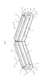
- FIG. 3 is a perspective view of a corner connecting element 1 according to the invention.
- the corner connecting element 1 consists in this embodiment of two in a connection angle of about 90 ° to each other arranged connecting elements 10, 20.
- the connecting elements 10, 20 of the corner connecting element 1 according to the invention are made in this embodiment of a metallic material and positively connected to each other.
- On the side 2 of the connecting element 10, 20 is in each case a spring element 11, 21 arranged in one piece.
- the spring element 11, 12 has in this embodiment the same length as the connecting element 10, 20.
- the spring element 11 is arranged at a distance from the spring element 21.
- the spring element 11, 12 has in each case a first spring limb 110, 210 and a second spring limb 111, 211, wherein a second spacer element 112, 212 is arranged on the first spring limb 110, 210.
- the second spacer element 112, 212 is approximately triangular in cross-section in this embodiment and connected in one piece with the first spring leg 110, 210.
- the first spring leg 110, 210 of the spring element 11, 21 is arranged in this embodiment approximately parallel to the side 2 of the connecting element 10, 20 via the second spring leg 111, 211 spaced.
- the second spring leg 111, 211 of the spring element 11, 21 is arranged approximately centrally on the side 2 of the connecting element 10, 20 in this embodiment.
- the support element 13 On the side 4 of the connecting element 10, 20 approximately centrally in the profile longitudinal direction relative to the spring element 11, 21, the support element 13 is arranged.
- the first spacer element 12, 22 On the side 3 of the connecting element 10, 20, the first spacer element 12, 22 is arranged parallel to the spring element 11, 21.
- the first spacer element 12, 22 of the connecting element 10, 20 is arranged centrally on the side 3 of the connecting element 10, 20 and parallel to the spring element 11, 21.
- the first spacer element 12, 22 is approximately prismatic in cross-section in this embodiment and has a smaller longitudinal extent than the connecting element 10, 20.
- Arranged opposite the first spacer element 12, 22 of the connecting element 10, 20 are two spaced-apart first spacer elements 12, 22 on the side 5 of the connecting element 10, 20.
- the spaced-apart first spacer elements 12, 22 on the side 5 of the connecting element 10, 20 are arranged in this embodiment by a form-fitting manner known per se bonding on the connecting element 10, 20 and consist of a metallic material.
- the connecting element 10, 20 of the corner connecting element 1 according to the invention has a hollow chamber 14, 24 arranged in the longitudinal direction and arranged approximately parallel to the spring element 11, 21.
- the hollow chamber 14, 24 of the connecting element 10, 20 is approximately circular in cross-section in this embodiment, has the same length extension as the connecting element 10, 20 and causes a reduction in the weight of the corner connecting element 1 according to the invention, without the stability and mechanical strength is impaired.
- the corner connecting element 1 according to the invention is economical and inexpensive to produce, in particular in the region of the miter 9 of oppositely arranged profile elements 30, 40 easy to install and leads for such profile elements 30, 40 to a gap-free or stepless connection in the corner. Furthermore, by the design of the corner connecting element 1 according to the invention for differently designed profile elements at any time compensation of manufacturing tolerances, especially in the region of the hollow chambers of the profile elements possible. The use of the corner connecting element 1 according to the invention for connecting each other approximately at right angles arranged profile elements 30, 40, which have at least one miter 9, is thus quickly and easily possible with visually appealing corner areas, which are formed step-free or gap-free.
Landscapes
- Engineering & Computer Science (AREA)
- Civil Engineering (AREA)
- Structural Engineering (AREA)
- Mutual Connection Of Rods And Tubes (AREA)
- Connector Housings Or Holding Contact Members (AREA)
- Connecting Device With Holders (AREA)
Description
- Die Erfindung betrifft ein Eckverbindungselement zur Verbindung voneinander etwa rechtwinklig gegenüberliegend angeordneten Profilelementen, welche wenigstens eine Gehrung aufweisen, umfassend zwei in einem Verbindungswinkel zueinander angeordneten Verbindungselementen, welche in wenigstens eine Hohlkammer der Profilelemente einbringbar sind.
- Derartige Eckverbindungselemente sind aus dem Stand der Technik vielfach bekannt und haben sich bewährt.
- So ist beispielsweise in der
DE 69711149 T2 ein Eckverbindungselement beschrieben zur dichten Verbindung von zwei zusammengefügten Profilen, deren Enden in einer dazwischenliegenden Kontaktfläche aneinander liegen, wobei die Verbindung zwischen diesen Profilen mittels eines Eckverbindungselementes hergestellt ist, das jeweils in beide dieser Profile eingreift, wobei das Eckverbindungselement ein weiches Element aufweist, und von diesem nach außen übersteht, so dass es zwischen den Enden der beiden wechselseitig in der Kontaktfläche aneinander liegenden Profile zusammengedrückt wird, wobei dieses weiche Element in dieser Fläche eine Diskontinuität im Kapillarweg von zwischen den beiden Enden der Profile eingeschlossenem Wasser sicherstellt, wodurch das Fließen von Wasser durch Kapillarwirkung entlang dieses Weges verhindert werden soll.
Dabei kann das weiche Element stabförmig ausgebildet und in einer Aussparung, einer Nut oder einer anderen Öffnung des Eckverbindungselements angeordnet sein. Das weiche Element ist dabei aus einem Kunststoffschaum gebildet.
Nachteilig bei diesem Eckverbindungselement wird gesehen, dass der Montageaufwand insbesondere des weichen Elementes hoch ist und dass insbesondere die Verbindung der im rechten Winkel einander gegenüberliegend angeordneten Profile sehr aufwendig und insbesondere im Bereich der Gehrung nicht vollumfänglich ohne Spaltbildung möglich ist. Ein weiterer Nachteil dieses Eckverbindungselementes besteht darin, dass bei fertigungsbedingten Toleranzen der Hohlkammern der gegenüberliegend angeordneten Profile beispielsweise das Einführen nicht möglich bzw. mit so viel Spiel möglich ist, dass insbesondere im Eckbereich der auf Gehrung einander gegenüberliegend angeordneten Profile keine exakte vorzugsweise rechtwinklige Fixierung dieser möglich ist, ohne das zumindest im Sichtbereich eine optisch unschöne Spaltbildung bzw. Stufenbildung auftritt. - Aus der
EP 1054133 ist ein weiteres Eckverbindungselement bekannt.
Dieses Eckverbindungselement für die Rahmeneckverbindung für zumindest zwei Rahmenhohlprofile weist zwei oder mehr Verbindungsschenkel auf, wobei diese Verbindungsschenkel in die auf Gehrung geschnittenen Rahmenhohlprofile eingreifen, wobei die Verbindungsschenkel jeweils ein oder mehrere Federblätter aufweisen, welche als Widerhaken gegen die Innenflächen der Rahmenhohlprofile anliegen.
Diese Federblätter sind vorzugsweise aus Metall beispielsweise aus Stahl hergestellt und sind in einer Nut der Verbindungselemente etwas rechtwinklig zur Hohlkammer der Rahmenprofile angeordnet. Dabei sind die Federblätter so ausgebildet, dass sie um ein vorgegebenes Maß aus den Federblattaufnahmen hervorragen.
Bei der Montage der Rahmenhohlprofile wird dieses Eckverbindungselement so in die Hohlkammer eingeschoben, dass sich das Federblatt aufgrund seiner Ausdehnung an der Innenseite der Hohlkammer verbiegt. Da die Rahmenprofile vorzugsweise aus Kunststoff oder Weichmetall wie zum Beispiel Alu gefertigt sind, kann sich somit das Federblatt, wel-ches aus einem wesentlichen härteren Werkstoff hergestellt ist, in die Innenfläche der Rahmenhohlprofile einkrallen und so nicht mehr herausgezogen werden.
Die Federblätter werden dabei in senkrecht zur Einschieberichtung angeordnete Nuten in die Verbindungselemente eingebracht und können sich somit über ihre gesamte Fläche an der Innenfläche der Rahmenhohlprofile einkrallen.
Nachteilig bei diesem Eckverbindungselement ist, dass die gewählte Geometrie des Verbindungselementes nicht auf die Spannungssituation beim Gehrungsschnitt abgestimmt ist und dass so beim Fixieren der Rahmenprofile insbesondere im Sichtbereich eine optisch unschöne Spaltbildung bzw. Stufenbildung entsteht.
Ein weiterer Nachteil des Eckverbindungselementes besteht darin, dass die einander etwa rechtwinklig gegenüberliegenden Rahmenhohlprofile im Bereich der Gehrung stufenartig nebeneinander bzw. übereinander liegen und nicht genau gegenüberliegend.
Ebenfalls nachteilig bei dem Eckverbindungselement wird gesehen, dass bei fertigungsbedingten Toleranzen in der Herstellung des Eckverbindungselementes und / oder der Rahmenhohlprofile es denkbar ist, dass das Eckverbindungselement nicht, nur sehr schwer oder mit sehr viel Spiel in die Hohlkammern der Rahmenhohlprofile einbringbar ist und so die Rückhaltekraft der Federblätter nicht oder nicht richtig wirken kann.
Weiterhin nachteilig bei diesem Eckverbindungselement ist, dass es beim Einschieben in die Hohlkammern der Rahmenhohlprofile zu Deformierungen dieser Profile im Sichtbereich kommen kann bzw. zu möglicherweise Schädigungen durch die in das Material der Rahmenhohlprofile eingreifenden Federblätter. - Hier setzt die Erfindung ein, die sich die Aufgabe gestellt hat, die Nachteile des bekannten Standes der Technik zu überwinden und ein Eckverbindungselement aufzuzeigen, welches wirtschaftlich und kostengünstig herstellbar ist, welches insbesondere im Bereich der Gehrung voneinander gegenüberliegend anzuordnenden Profile einfach montierbar ist und für derartige Profilelemente zu einer spaltfreien bzw. stufenfreien Verbindung im Eckbereich sorgt.
- Es konnte überraschend festgestellt werden, dass ein Eckverbindungselement zur Verbindung voneinander etwa rechtwinklig gegenüberliegend angeordneten Profilelementen, welche wenigstens eine Gehrung aufweisen, umfassend zwei in einem Verbindungswinkel zueinander angeordneten Verbindungselementen, welche in wenigstens eine Hohlkammer der Profilelemente einbringbar sind, sich dadurch auszeichnet, dass wenigstens eine Seite des Verbindungselementes vollständig beabstandet von einer Wand der Hohlkammer des Profilelementes, mit dieser über wenigstens ein Federelement in Wirkverbindung stehend, angeordnet ist. Das erfindungsgemäße Eckverbindungselement zeichnet sich dadurch aus, dass durch deren vorteilhafte Ausgestaltung ein Ausgleich der herstellungsbedingten Toleranzen insbesondere der Profile sowohl in waagerechter als auch in senkrechter Richtung möglich ist und dass dadurch eine wesentliche Verbesserung der Qualität sowohl der mechanischen Eigenschaften als auch der optischen Eigenschaften in der Gehrung der verbundenen Profilelemente realisiert ist. Ein weiterer Vorteil des erfindungsgemäßen Eckverbindungselementes besteht darin, dass mit deren Hilfe eine schnelle, einfache und kostengünstige Montage von Rahmen für Türen, Fenster und dergleichen möglich ist.
- Das erfindungsgemäße Eckverbindungselement ist vorteilhafterweise so ausgebildet, dass das Federelement etwa parallel zur Längsrichtung des Profilelements am Verbindungselement angeordnet ist. Hierdurch ist es möglich, dass bei bestimmungsgemäßem Einbringen des Eckverbindungselementes in etwa rechtwinklig gegenüberliegend angeordnete Profilelemente keine mechanischen Belastungen bzw. Deformationen im Bereich der Gehrung entstehen und somit keine Stufenbildung bzw. Spaltbildung in diesem optisch und mechanisch sensiblen Bereich zu verzeichnen sind.
- Weiterhin zeichnet sich das erfindungsgemäße Eckverbindungselement dadurch aus, dass das Federelement wenigstens einen Federschenkel aufweist, wobei der Federschenkel vorteilhafterweise in etwa einem spitzen Winkel zur Seite des Verbindungselements angeordnet ist. Hierdurch ist es vorteilhafterweise möglich, fertigungsbedingte Toleranzen insbesondere der Hohlkammer der Profilelemente auszugleichen, da der Federschenkel beim Einbringen in die Hohlkammer des Profilelementes durch die Wand der Hohlkammer elastisch zu einer Seite des Verbindungselementes nachgibt und so entsprechende Toleranzschwankungen optimal ausgleicht.
- Es hat sich weiterhin als vorteilhaft herausgestellt, dass das erfindungsgemäße Eckverbindungselement an wenigstens einem Federschenkel des Federelements wenigstens ein zweites Distanzelement aufweist. Dieses zweite Distanzelement ist vorteilhafterweise im Querschnitt etwa prismatisch, rund, halbrund, oval, dreieckig, mehreckig und dergleichen ausgebildet und führt dazu, dass das in die Hohlkammer der Profilelemente eingeführte Eckverbindungselement immer fest in der Hohlkammer des Profilelementes angeordnet ist, ohne dass zusätzliche mechanische Befestigungen wie bspw. Schrauben bzw. stoffschlüssige Verbindungen über an sich bekannte Klebstoffsysteme erforderlich sind und dass trotzdem keine Stufen und/oder Spalten zwischen den einander rechtwinklig gegenüberliegend angeordneten Profilelementen entstehen.
- In einer weiteren vorteilhaften Ausgestaltung des erfindungsgemäßen Eckverbindungselementes ist an wenigstens einer Seite des Verbindungselementes wenigstens ein Auflageelement angeordnet. Dieses Auflageelement, welches bspw. an der dem Federelement gegenüberliegenden Seite angeordnet ist, führt insbesondere beim Einschieben des Eckverbindungselementes in die Hohlkammer der Profilelemente zu einem besseren Gleiten und zu einer exakten Positionierung des erfindungsgemäßen Eckverbindungselementes in der Hohlkammer des Profilelementes.
- Es hat sich ebenfalls als vorteilhaft herausgestellt, dass an wenigstens einer Seite des Verbindungselementes wenigstens ein, etwa parallel zum Federelement angeordnetes, erstes Distanzelement angeordnet ist. Dieses erste Distanzelement, welches beispielsweise einstückig am Verbindungselement angeordnet ist und im Querschnitt etwa prismatisch, rund, halbrund, oval, dreieckig, mehreckig und dergleichen ausgebildet ist, bewirkt beim erfindungsgemäßen Eckverbindungselement, dass sich dieses in der Hohlkammer des Profilelementes entsprechend ausrichtet und insbesondere fertigungsbedingte Toleranzen der Profilelemente in waagerechte sowie senkrechte Richtung ausgeglichen werden.
- Es hat sich weiterhin als vorteilhaft herausgestellt bei dem erfindungsgemäßen Eckverbindungselement, dass das Federelement und / oder das Distanzelement und / oder das Auflageelement einstückig am Verbindungselement angeordnet ist. Dies führt neben einer wirtschaftlichen und kostengünstigen Herstellung des erfindungsgemäßen Eckverbindungselementes zu einer einfachen Montierbarkeit und durch die Dimensionierung insbesondere der Geometrie des Federelementes sowie des Distanzelementes dazu, dass fertigungsbedingte Toleranzen der Profilelemente einfach ausgeglichen werden können.
- Dabei hat es sich ebenfalls als vorteilhaft herausgestellt, dass bei dem erfindungsgemäßen Eckverbindungselement das Federelement und / oder das Distanzelement und / oder das Auflageelement kraft- und / oder formschlüssig am Verbindungselement angeordnet ist. Durch diese vorteilhafte Ausgestaltung ist es möglich, unterschiedliche Werkstoffe für die einzelnen Elemente des Verbindungselementes zu verwenden und diese den entsprechenden Anforderungen der zu verbindenden Profilelemente so anzupassen, dass das erfindungsgemäße Eckverbindungselement zu einer optisch ansprechenden und mechanisch sicheren Verbindung der Profilelemente beiträgt. Ein weiterer Vorteil besteht darin, dass bei einem späteren Rückbau der aus den Profilelementen hergestellten Rahmen ein werkstoffgerechtes Recycling der einzelnen Elemente problemlos möglich ist.
- Es hat sich auch weiterhin als vorteilhaft beim erfindungsgemäßen Eckverbindungselement herausgestellt, dass wenigstens eine Wand der Hohlkammer des Profilelementes wenigstens ein drittes Distanzelement aufweist. Bei dieser vorteilhaften Ausgestaltung ist eine kostengünstige und wirtschaftliche Einbringung des dritten Distanzelementes, welches dabei bspw. an der dem Federelement des Verbindungselements gegenüberliegende Wand der Hohlkammer des Profilelementes angeordnet ist, realisierbar, so dass verschieden dimensionierte Federelemente des erfindungsgemäßen Eckverbindungselementes für die Verbindung der Profilelemente einsetzbar sind.
- Dabei hat sich als besonders vorteilhaft herausgestellt, dass bei dem erfindungsgemäßen Eckverbindungselement das erste Distanzelement und / oder das zweite Distanzelement und / oder das dritte Distanzelement im Querschnitt etwa prismatisch, rund, halbrund, oval, dreieckig, mehreckig und dergleichen ausgebildet ist. Hierdurch ist eine einfache Montage des erfindungsgemäßen Eckverbindungselements in den Hohlkammern der Profilelemente möglich und das Eckverbindungselement sitzt straff und fest ohne zusätzliche Befestigungsmittel in der Hohlkammer des Profilelementes.
- Ein weiterer wesentlicher Vorteil des erfindungsgemäßen Eckverbindungselementes ist, dass das Federelement und / oder das Auflageelement und / oder das Distanzelement in etwa die gleiche Längenausdehnung aufweist wie das Verbindungselement. Hierdurch ist eine kostengünstige und wirtschaftliche Herstellung des erfindungsgemäßen Eckverbindungselementes möglich. Weiterhin kann insbesondere durch die Länge der Verbindungselemente des erfindungsgemäßen Eckverbindungselementes eine optisch ansprechende und mechanisch sichere Verbindung der mit einer Gehrung versehenen Profilelemente realisiert werden, egal wie lang, breit bzw. dick diese Profilelemente ausgestaltet sind.
- Weiterhin vorteilhaft weist das erfindungsgemäße Eckverbindungselement wenigstens eine im Verbindungselement angeordnete Hohlkammer auf. Diese führt neben der Materialersparnis und den damit verbundenen, günstigen Herstellungskosten auch zu einer Gewichtsreduzierung des erfindungsgemäßen Eckverbindungselementes, ohne dass die zu realisierende Verbindung der Profilelemente beeinträchtigt ist.
- Dabei hat es sich weiterhin als vorteilhaft herausgestellt, dass die Hohlkammer in etwa parallel zum Federelement des Verbindungselementes angeordnet ist, was vorteilhafterweise zu einer kostengünstigen Herstellung des erfindungsgemäßen Eckverbindungselementes führt.
- In einer ebenfalls vorteilhaften Ausgestaltung des erfindungsgemäßen Eckverbindungselementes ist der erste Federschenkel des Federelementes etwa parallel zur einen Seite des Verbindungselementes über wenigstens einen zweiten Federschenkel beabstandet angeordnet. Durch diese vorteilhafte Ausführungsform lässt sich das erfindungsgemäße Eckverbindungselement so in die Hohlkammern der Profilelemente einbringen, dass insbesondere im späteren Sichtbereich der aus den Profilelementen hergestellten Rahmen, Türen und dergleichen keine Abzeichnungen bzw. Verformungen erkennbar sind und dass insbesondere im Bereich der auf Gehrung einander gegenüberliegend angeordneten Profilelemente ein fester mechanischer Sitz und keine optisch sichtbare Stufe realisiert ist.
Dabei sind der erste und der zweite Federschenkel des Federelementes einstückig miteinander verbunden und ebenfalls einstückig am Verbindungselement angeordnet. Der erste Federschenkel des Federelementes ist dabei etwa parallel beabstandet zum Verbindungselement angeordnet, während der zweite Federschenkel rechtwinklig am Verbindungselement angeordnet ist.
In einer weiteren vorteilhaften Ausgestaltung ist der zweite Federschenkel des Federelementes mittig in Längsrichtung des Verbindungselementes an diesem angeordnet. Es liegt jedoch auch im Rahmen der Erfindung, dass der zweite Federschenkel des Federelementes außermittig parallel zur einen Seite des Verbindungselementes an diesem angeordnet ist. - Ebenfalls vorteilhaft bei dem erfindungsgemäßen Eckverbindungselement ist, dass das eine Verbindungselement einstückig mit dem anderen Verbindungselement verbunden ist. Hierdurch ist eine kostengünstige Herstellung sowie eine ausreichende mechanische Festigkeit der Verbindungselemente des erfindungsgemäßen Eckverbindungselementes realisierbar.
- Es hat sich jedoch auch weiterhin als vorteilhaft herausgestellt, dass das eine Verbindungselement form- und / oder kraftschlüssig mit dem anderen Verbindungselement verbunden ist. Hierdurch ist es vorteilhafterweise möglich, die Verbindungselemente beispielsweise aus unterschiedlichen Werkstoffen herzustellen und erst für die Herstellung der Verbindung zwischen den Profilelementen kostengünstig ineinanderzufügen und bei Rückbau wieder zu recyceln.
- Dabei kann es sich ebenfalls als vorteilhaft herausstellen, dass das Verbindungselement aus einem metallischen Werkstoff hergestellt ist. Dies führt zu einer insbesondere mechanischen Stabilisierung der zu verbindenden Profilelemente.
- Weiterhin hat es sich ebenfalls als vorteilhaft herausgestellt, dass das Verbindungselement aus einem polymeren Werkstoff hergestellt ist. Hierdurch ist einerseits eine kostengünstige und einfache Herstellung beispielsweise im an sich bekannten Spritzgießverfahren möglich, während andererseits das erfindungsgemäße Eckverbindungselement neben dem geringen Gewicht beispielsweise beim Einsatz der Profilelemente zur Herstellung von Rahmen für Fenster, Türen, Kühl- bzw. Gefriergeräte immer korrosionsbeständig ausgebildet ist.
- Unter polymerem Werkstoff sind Materialien gemeint, wie Polyvinylchlorid (PVC); Polyolefin, wie Polypropylen (PP) oder Polyethylen (PE); styrolbasiertes Polymer, wie Polystyrol (PS) oder Styrol-Butadien-Copolymer mit überwiegendem Styrolanteil (SB) oder Acrylnitril-Styrol-Acrylester-Copolymere (ASA) oder Acrylnitril-Butadien-Styrol-Copolymere (ABS) oder Styrolacrylnitril (SAN); Polybutylentherephthalat (PBT); Polyethylentherephthalat (PET); Polyoxymethylen (POM); Polyamid (PA); Polymethylmethacrylat (PMMA); Polyphenylenoxid (PPO); Polyetheretherketon (PEEK); Polyphenylensulfid (PPS); Liquid Crystal Polymer (LCP); Polyamidimide (PAI); Polyvinylidenfluorid (PVDF); Polyphenylsulfon (PPSU); Polyaryletherketon (PAEK); Polyacrylnitril (PAN); Polychlortrifluorethylen (PCTFE); Polyetherketon (PEK); Polyimid (P1); Polyisobuten (PIB); Polyphthalamid (PPA); Polypyrrol PPY);Polytetrafluorethylen (PTFE); Polyurethan (PUR); Polyvinylalkohol (PVA); Polyvinylacetat (PVAC); Polyvinylidenchlorid (PVDC); sowie Mischungen aus wenigstens zwei dieser Materialien.
Dabei können dem polymeren Werkstoff des Profilelementes geeignete Füll- und / oder Verstärkungsstoffe beigemischt sein, die die mechanischen Eigenschaften positiv beeinflussen insbesondere Glasfasern, Glaskugeln aber auch Füllstoffe wie Kreide, Teflon und dergleichen. Die Füll- und / oder Verstärkungsstoffe sind dabei in Mengen von etwa 5 bis 50 Gew.-%, vorzugsweise 10 bis 35 Gew.-%, bezogen auf die Gesamtmasse, enthalten. - Das erfindungsgemäße Eckverbindungselement soll nun an diesen nicht einschränkenden Ausführungsbeispielen näher beschrieben werden.
- Es zeigen:
- Fig. 1
- perspektivische Darstellung eines erfindungsgemäßen Eckverbindungselementes mit zwei etwa rechtwinklig gegenüberliegend angeordneten Profilelementen
- Fig. 2
- Vorderansicht eines erfindungsgemäßen Eckverbindungselementes in einem Profilelement
- Fig. 3
- perspektivische Darstellung eines erfindungsgemäßen Eckverbindungselementes
- In der
Fig. 1 ist eine perspektivische Darstellung eines erfindungsgemäßen Eckverbindungselementes 1 mit zwei etwa rechtwinklig einander gegenüberliegend angeordneten Profilelementen 30, 40 dargestellt. - Die Profilelemente 30, 40 weisen jeweils eine in Profillängsrichtung ausgebildete Hohlkammer 31, 41 auf. Die Hohlkammer 31 des Profilelements 30 ist dabei von den Wänden 32, 33, 34, 35 umgeben, während die Hohlkammer 41 des Profilelements 40 durch die Wände 42, 43, 44, 45 umschlossen ist.
Das erfindungsgemäße Eckverbindungselement 1 ist über das in dieser Figur nicht erkennbare Verbindungselement 10 in der Hohlkammer 31 des Profilelements 30 angeordnet. Die Profilelemente 30, 40 weisen an ihren einem freien Ende eine Gehrung 9 von etwa 45° auf, über die sie über das erfindungsgemäße Eckverbindungselement 1 aneinander angefügt und miteinander verbunden werden.
Dabei wird das Verbindungselement 20 des Eckverbindungselementes 1 in die Hohlkammer 41 des Profilelementes 40 eingeschoben und das Profilelement 40 soweit längs über das Verbindungselement 20 bewegt, bis die Gehrung 9 des Profilelementes 40 direkt neben der Gehrung 9 des Profilelementes 30 angeordnet ist.
Durch das erfindungsgemäße Eckverbindungselement 1 ist es somit möglich, die Profilelemente 30,40 an der Gehrung 9 so miteinander zu verbinden, dass kein Spalt zwischen den Gehrungen 9 sichtbar ist und das insbesondere keine Stufenbildung durch versetzt voneinander angeordnete Gehrungen 9 der Profilelemente 30, 40 auftritt.
Durch die vorteilhafte Ausgestaltung des erfindungsgemäßen Eckverbindungselementes 1 ist es somit möglich, dass das Verbindungselement 10, 20 des Eckverbindungselementes 1 einfach und schnell in Verschieberichtung A in die Hohlkammer 31, 41 des Profilelementes 30, 40 einführbar und in dieser kraftschlüssig fixierbar ist. - In der
Fig. 2 ist die Vorderansicht eines erfindungsgemäßen Eckverbindungselementes 1 in einem Profilelement 40 dargestellt.
Das Eckverbindungselement 1 umfasst zwei in einem Verbindungswinkel von etwa 90° zueinander angeordnete Verbindungselemente 10, 20 wobei das Verbindungselement 10 in der Hohlkammer 41 des Profilelementes 40 eingebracht ist, die in diesem Ausführungsbeispiel durch die Wände 42, 43, 44, 45 begrenzt ist.
In diesem Ausführungsbeispiel ist die Seite 2 des Verbindungselementes 10 vollständig beabstandet von der Wand 45 der Hohlkammer 41 des Profilelementes 40, mit dieser über ein Federelement 11 in Wirkverbindung stehend, angeordnet.
Das Federelement 11 ist in diesem Ausführungsbeispiel in Längsrichtung etwa parallel zur Wand 45 des Profilelements 40 ausgebildet und weist einen ersten Federschenkel 110 und einen zweiten Federschenkel 111 auf. - Der erste Federschenkel 110 des Federelements 11 ist in diesem Ausführungsbeispiel etwa parallel zur Seite 2 des Verbindungselements 10 über den zweiten Federschenkel 111 beabstandet angeordnet.
Der erste Federschenkel 110 liegt in diesem Ausführungsbeispiel in etwa einem spitzen Winkel zur Seite 2 des Verbindungselementes 10 bzw. auch zur Wand 45 des Profilelementes 40 direkt an dieser an.
Das Federelement 11, welches an der im späteren Gebrauch sichtbaren Wand 45 des Profilelementes 40 anliegt, führt zu einem senkrechten Toleranzausgleich des Profilelementes 40, ohne das auf der die Sichtseite bildenden Wand 45 Abzeichnungen bzw. Verformungen erkennbar sind. - An der dem Federelement 11 gegenüberliegenden Seite 4 des Verbindungselements 10 ist ein Auflageelement 13 angeordnet, welches im Querschnitt etwa rechteckig ausgebildet und mit seiner größeren Fläche an der Wand 43 des Profilelementes 40 anliegt. Das Auflageelement 13 des Verbindungselements 10 ist in diesem Ausführungsbeispiel etwa parallel zur Wand 43 des Profielements 40 ausgebildet und führt zu einer guten Einführbarkeit des Verbindungselements 10 in die Hohlkammer 41 des Profilelementes 40. Ein weiterer Vorteil des Auflageelements 13 ist es, dass das Verbindungselement 10 in der Hohlkammer 41 des Profilelementes 40 sicher positionierbar ist.
Das Eckverbindungselement 1 weist in diesem Ausführungsbeispiel an seiner Wand 5 zwei erste Distanzelemente 12 auf. Das erste Distanzelement 12 ist in diesem Ausführungsbeispiel so ausgebildet, dass es im Querschnitt eine etwa dreieckförmige Gestalt aufweist. An der Wand 44 des Profilelements 40 sind in diesem Ausführungsbeispiel die zwei voneinander beabstandet angeordnete erste Distanzelemente 12 angeordnet. Die zwei voneinander beabstandet angeordneten Distanzelemente 12 an der Seite 5 des Verbindungselements 10 führen dazu, dass beim Einführen des Eckverbindungselementes 1 in die Hohlkammer 41 des Profilelementes 40 sich dieses ausrichtet, wodurch die senkrechten und/oder waagerechten Fertigungstoleranzen ausgeglichen sind.
Das erste Distanzelement 12 des Verbindungselements 10 ist in diesem Ausführungsbeispiel einstückig mit dem Verbindungselement 10 verbunden und aus einem polymeren Werkstoff wie beispielsweise Polyamid hergestellt.
Die Verbindungselemente 10, 20 des erfindungsgemäßen Eckverbindungselementes 1 sind in diesem Ausführungsbeispiel einstückig miteinander verbunden, weisen einen etwa quadratischen Querschnitt auf und sind zusammen mit dem Federelement 11, dem ersten Distanzelement 12 sowie dem Auflageelement 13 im an sich bekannten Spritzgießverfahren hergestellt.
Es liegt jedoch auch im Rahmen der Erfindung, dass das Federelement 11 und / oder das erste Distanzelement 12 und / oder das Auflageelement 13 kraft- und / oder formschlüssig am Verbindungselement 10 angeordnet sind.
Es liegt weiterhin im Rahmen der Erfindung, dass das Federelement 11 nur einen Federschenkel 111 aufweist, der bspw. in etwa einem spitzen Winkel an der Seite 2 des Verbindungselements 10 angeordnet ist.
Der zweite Federschenkel 111 des Federelements 11 ist in diesem Ausführungsbeispiel an der Seite 2 des Verbindungselements 10 außermittig angeordnet. Der erste Federschenkel 110 ist in seiner Breite etwa mittig zur Seite 2 des Verbindungselements 10 gegenüber dem Auflageelement 13 angeordnet.
In der Hohlkammer 41 des Profilelementes 40 ist an der Wand 42 ein drittes Distanzelement 8 angeordnet, welches im Querschnitt etwa dreieckförmig ausgebildet ist.
Das dritte Distanzelement 8 ist einstückig mit der Wand 42 des Profilelements 40 verbunden und führt zu einer besseren Fixierung bzw. Führung des Verbindungselements 10 des Eckverbindungselementes 1. Durch die Anordnung des dritten Distanzelements 8 an einer Wand der Hohlkammer 41 des Profilelements 40 ist es somit vorteilhafterweise möglich, beliebig lange Eckverbindungselemente 1 einzubringen, je nachdem wie groß die aus den Profilelementen 30, 40 zu fertigenden Rahmen für Fenster, Türen und dergleichen sein müssen. - In der
Fig. 3 ist eine perspektivische Darstellung eines erfindungsgemäßen Eckverbindungselementes 1 dargestellt.
Das Eckverbindungselement 1 besteht in diesem Ausführungsbeispiel aus zwei in einem Verbindungswinkel von etwa 90° zueinander angeordneten Verbindungselementen 10, 20. Die Verbindungselemente 10, 20 des erfindungsgemäßen Eckverbindungselementes 1 sind in diesem Ausführungsbeispiel aus einem metallischen Werkstoff hergestellt und formschlüssig miteinander verbunden.
An der Seite 2 des Verbindungselements 10, 20 ist jeweils ein Federelement 11, 21 einstückig angeordnet. Das Federelement 11, 12 weist in diesem Ausführungsbeispiel die gleiche Länge wie das Verbindungselement 10, 20 auf.
Im Eckbereich, in dem das Verbindungselement 10 formschlüssig mit dem Verbindungselement 20 verbunden ist, ist das Federelement 11 beabstandet vom Federelement 21 angeordnet. - Das Federelement 11,12 weist jeweils einen ersten Federschenkel 110, 210 sowie einen zweiten Federschenkel 111, 211 auf, wobei am ersten Federschenkel 110, 210 ein zweites Distanzelement 112, 212 angeordnet ist.
Das zweite Distanzelement 112, 212 ist in diesem Ausführungsbeispiel im Querschnitt etwa dreieckförmig ausgebildet und einstückig mit dem ersten Federschenkel 110, 210 verbunden.
Der erste Federschenkel 110, 210 des Federelementes 11, 21 ist in diesem Ausführungsbeispiel etwa parallel zur Seite 2 des Verbindungselements 10, 20 über den zweiten Federschenkel 111, 211 beabstandet angeordnet.
Der zweite Federschenkel 111, 211 des Federelements 11, 21 ist in diesem Ausführungsbeispiel etwa mittig an der Seite 2 des Verbindungselements 10, 20 angeordnet.
An der Seite 4 des Verbindungselementes 10, 20 etwa mittig in Profillängsrichtung gegenüber dem Federelement 11, 21 ist das Auflageelement 13 angeordnet.
An der Seite 3 des Verbindungselements 10, 20 ist parallel zum Federelement 11, 21 das erste Distanzelement 12, 22 angeordnet. Das erste Distanzelement 12, 22 des Verbindungselements 10, 20 ist in diesem Ausführungsbeispiel mittig an der Seite 3 des Verbindungselements 10, 20 sowie parallel zum Federelement 11, 21 angeordnet.
Das erste Distanzelement 12, 22 ist in diesem Ausführungsbeispiel im Querschnitt etwa prismatisch ausgebildet und weist eine geringere Längenausdehnung als das Verbindungselement 10, 20 auf.
Dem ersten Distanzelement 12, 22 des Verbindungselements 10, 20 gegenüberliegend angeordnet sind zwei voneinander beabstandet positionierte erste Distanzelemente 12, 22 an der Seite 5 des Verbindungselements 10, 20 angeordnet.
Die voneinander beabstandet angeordneten ersten Distanzelemente 12, 22 an der Seite 5 des Verbindungselement 10, 20 sind in diesem Ausführungsbeispiel formschlüssig durch an sich bekannte Verklebung am Verbindungselement 10, 20 angeordnet und bestehen aus einem metallischen Werkstoff.
Das Verbindungselement 10, 20 des erfindungsgemäßen Eckverbindungselementes 1 weist in diesem Ausführungsbeispiel eine in Längsrichtung angeordnete und etwa parallel zum Federelement 11, 21 angeordnete Hohlkammer 14, 24 auf. Die Hohlkammer 14, 24 des Verbindungselements 10, 20 ist in diesem Ausführungsbeispiel im Querschnitt etwa kreisförmig ausgebildet, weist die gleiche Längenausdehnung wie das Verbindungselement 10, 20 auf und bewirkt eine Reduzierung des Gewichtes des erfindungsgemäßen Eckverbindungselementes 1, ohne das die Stabilität und die mechanische Festigkeit beeinträchtigt wird. - In dieser Ausführungsform ist das erfindungsgemäße Eckverbindungselement 1 wirtschaftlich und kostengünstig herstellbar, ist insbesondere im Bereich der Gehrung 9 von einander gegenüberliegend anzuordnenden Profilelementen 30, 40 einfach montierbar und führt für derartige Profilelemente 30, 40 zu einer spaltfreien bzw. stufenfreien Verbindung im Eckbereich.
Weiterhin ist durch die Ausgestaltung des erfindungsgemäßen Eckverbindungselementes 1 für verschieden konstruierte Profilelemente jederzeit ein Ausgleich der fertigungsbedingten Toleranzen insbesondere im Bereich der Hohlkammern der Profilelemente möglich.
Der Einsatz des erfindungsgemäßen Eckverbindungselementes 1 zur Verbindung voneinander etwa rechtwinklig gegenüberliegend angeordneten Profilelementen 30, 40, welche mindestens eine Gehrung 9 aufweisen, ist somit schnell und problemlos möglich bei optisch ansprechenden Eckbereichen, welche stufenfrei bzw. spaltfrei ausgebildet sind.
Claims (14)
- Eckverbindungselement (1) zur Verbindung voneinander etwa rechtwinklig gegenüberliegend angeordneten Profilelementen (30, 40), welche wenigstens eine Gehrung (9) aufweisen, umfassend zwei in einem Verbindungswinkel zueinander angeordneten Verbindungselementen (10, 20), welche in wenigstens eine Hohlkammer (31, 41) der Profilelemente (30, 40) einbringbar sind, dadurch gekennzeichnet, dass wenigstens eine Seite (2, 3, 4, 5) des Verbindungselements (10, 20) vollständig beabstandet von einer Wand (32, 42, 33, 43, 34, 44, 35, 45) der Hohlkammer (31, 41) des Profilelements (30, 40), mit dieser über wenigstens ein Federelement (11, 21) in Wirkverbindung stehend, angeordnet ist, wobei das Federelement (11, 21) etwa parallel zur Längsrichtung des Profilelements (30, 40) am Verbindungselement (10, 20) angeordnet ist.
- Eckverbindungselement (1) nach Anspruch 1, dadurch gekennzeichnet, dass das Federelement (11, 21) wenigstens einen Federschenkel (110, 210, 111, 211) aufweist.
- Eckverbindungselement (1) nach Anspruch 2, dadurch gekennzeichnet, dass der Federschenkel (110, 210, 111, 211) in etwa einem spitzen Winkel zur Seite (2) des Verbindungselements (10, 20) angeordnet ist.
- Eckverbindungselement (1) nach Anspruch 2 und 3, dadurch gekennzeichnet, dass wenigstens ein Federschenkel (110, 210, 111, 211) wenigstens ein zweites Distanzelement (112, 212) aufweist.
- Eckverbindungselement (1) nach einem der vorhergehenden Ansprüche, dadurch gekennzeichnet, dass an der dem Federelement (11, 21) gegenüberliegenden Seite (4) des Verbindungselements (10,20) wenigstens ein Auflageelement (13, 23) angeordnet ist.
- Eckverbindungselement (1) nach einem der vorhergehenden Ansprüche, dadurch gekennzeichnet, dass an wenigstens einer Seite (2, 3, 4, 5) des Verbindungselements (10, 20) wenigstens ein, etwa parallel zum Federelement (11, 21) angeordnetes, erstes Distanzelement (12, 22) angeordnet ist.
- Eckverbindungselement (1) nach einem der vorhergehenden Ansprüche, dadurch gekennzeichnet, dass das Federelement (11, 21) und / oder das Distanzelement (12, 22) und / oder das Auflageelement (13, 23) einstückig am Verbindungselement (10, 20) angeordnet ist.
- Eckverbindungselement (1) nach einem der vorhergehenden Ansprüche, dadurch gekennzeichnet, dass das Federelement (11, 21) und / oder das Distanzelement (12, 22) und / oder das Auflageelement (13, 23) kraft- und / oder formschlüssig am Verbindungselement (10, 20) angeordnet ist.
- Eckverbindungselement (1) nach einem der vorhergehenden Ansprüche, dadurch gekennzeichnet, dass wenigstens eine Wand (32, 42, 33, 43, 34, 44, 35, 45) der Hohlkammer (31, 41) des Profilelements (30, 40) wenigstens ein drittes Distanzelement (8) aufweist.
- Eckverbindungselement (1) nach einem der vorhergehenden Ansprüche, dadurch gekennzeichnet, dass das erste Distanzelement (12, 22) und/oder das zweite Distanzelement (112, 212) und/oder das dritte Distanzelement (8) im Querschnitt etwa prismatisch, rund, halbrund, oval, dreieckig, mehreckig und dgl. ausgebildet ist.
- Eckverbindungselement (1) nach einem der vorhergehenden Ansprüche, dadurch gekennzeichnet, dass das Federelement (11, 21) und/oder das Auflageelement (13, 33) und/oder das Distanzelement (12, 22, 112, 212) in etwa die gleiche Längenausdehnung aufweist wie das Verbindungselement (10, 20).
- Eckverbindungselement (1) nach einem der vorhergehenden Ansprüche, dadurch gekennzeichnet, dass der erste Federschenkel (110, 210) des Federelements (11, 21) etwa parallel zur Seite (2) des Verbindungselements (10, 20) über den zweiten Federschenkel (111, 211) beabstandet angeordnet ist.
- Eckverbindungselement (1) nach einem der vorhergehenden Ansprüche, dadurch gekennzeichnet, dass das Verbindungselement (10) einstückig mit dem Verbindungselement (20) verbunden ist.
- Eckverbindungselement (1) nach einem der vorhergehenden Ansprüche, dadurch gekennzeichnet, dass das Verbindungselement (10) form- und / oder kraftschlüssig mit dem Verbindungselement (20) verbunden ist.
Applications Claiming Priority (1)
| Application Number | Priority Date | Filing Date | Title |
|---|---|---|---|
| DE202012102510U DE202012102510U1 (de) | 2012-07-06 | 2012-07-06 | Eckverbindungselement |
Publications (3)
| Publication Number | Publication Date |
|---|---|
| EP2682555A2 true EP2682555A2 (de) | 2014-01-08 |
| EP2682555A3 EP2682555A3 (de) | 2014-08-13 |
| EP2682555B1 EP2682555B1 (de) | 2018-06-13 |
Family
ID=48875480
Family Applications (1)
| Application Number | Title | Priority Date | Filing Date |
|---|---|---|---|
| EP13174623.2A Active EP2682555B1 (de) | 2012-07-06 | 2013-07-02 | Eckverbindungselement |
Country Status (3)
| Country | Link |
|---|---|
| EP (1) | EP2682555B1 (de) |
| DE (1) | DE202012102510U1 (de) |
| TR (1) | TR201810512T4 (de) |
Cited By (2)
| Publication number | Priority date | Publication date | Assignee | Title |
|---|---|---|---|---|
| CN107223001A (zh) * | 2017-06-30 | 2017-09-29 | 苏州广能电子科技有限公司 | 控制台框架用角件 |
| CN107223002A (zh) * | 2017-06-30 | 2017-09-29 | 苏州广能电子科技有限公司 | 框架连接用角件 |
Families Citing this family (2)
| Publication number | Priority date | Publication date | Assignee | Title |
|---|---|---|---|---|
| RU199347U1 (ru) * | 2020-05-26 | 2020-08-28 | Андрей Сергеевич Поддубный | Угловое соединение полых профилей рамы или окон |
| RU203128U1 (ru) * | 2020-10-07 | 2021-03-23 | Вячеслав Михайлович Обатуров | Угловое соединение полых профилей рам окон и москитных сеток |
Citations (2)
| Publication number | Priority date | Publication date | Assignee | Title |
|---|---|---|---|---|
| EP1054133A1 (de) | 1999-05-15 | 2000-11-22 | SKS Stakusit Bautechnik GmbH | Rahmeneckverbindung für zwei Rahmenhohlprofile |
| DE69711149T2 (de) | 1996-10-29 | 2002-10-31 | Technal, Toulouse | Abdichtungsvorrichtung des Stosses zwischen zwei Profilen eines Tür-, Fenster oder dgl. Rahmens |
Family Cites Families (7)
| Publication number | Priority date | Publication date | Assignee | Title |
|---|---|---|---|---|
| BE570357A (de) * | ||||
| FR1555524A (de) * | 1967-05-25 | 1969-01-31 | ||
| DE8125504U1 (de) * | 1981-06-09 | 1981-12-10 | Syma Intercontinental AG, 9533 Kirchberg | Klemmsteckverbinder |
| GB2222220A (en) * | 1988-08-23 | 1990-02-28 | Rehau Ag & Co | Corner connecting piece |
| DE9007486U1 (de) * | 1989-11-24 | 1992-01-23 | PURAL Profilwerk GmbH, 6086 Riedstadt | Verbindungsformstück für Bauprofile |
| FR2904068A1 (fr) * | 2006-07-18 | 2008-01-25 | Norsk Hydro As | Dispositif de liaison entre deux extremites de profiles tubulaires destines a former un assemblage angulaire. |
| TWI507612B (zh) * | 2011-09-08 | 2015-11-11 | Au Optronics Corp | 鎖角器及其框架組合 |
-
2012
- 2012-07-06 DE DE202012102510U patent/DE202012102510U1/de not_active Expired - Lifetime
-
2013
- 2013-07-02 EP EP13174623.2A patent/EP2682555B1/de active Active
- 2013-07-02 TR TR2018/10512T patent/TR201810512T4/tr unknown
Patent Citations (2)
| Publication number | Priority date | Publication date | Assignee | Title |
|---|---|---|---|---|
| DE69711149T2 (de) | 1996-10-29 | 2002-10-31 | Technal, Toulouse | Abdichtungsvorrichtung des Stosses zwischen zwei Profilen eines Tür-, Fenster oder dgl. Rahmens |
| EP1054133A1 (de) | 1999-05-15 | 2000-11-22 | SKS Stakusit Bautechnik GmbH | Rahmeneckverbindung für zwei Rahmenhohlprofile |
Cited By (2)
| Publication number | Priority date | Publication date | Assignee | Title |
|---|---|---|---|---|
| CN107223001A (zh) * | 2017-06-30 | 2017-09-29 | 苏州广能电子科技有限公司 | 控制台框架用角件 |
| CN107223002A (zh) * | 2017-06-30 | 2017-09-29 | 苏州广能电子科技有限公司 | 框架连接用角件 |
Also Published As
| Publication number | Publication date |
|---|---|
| EP2682555A3 (de) | 2014-08-13 |
| DE202012102510U1 (de) | 2013-10-08 |
| TR201810512T4 (tr) | 2018-08-27 |
| EP2682555B1 (de) | 2018-06-13 |
Similar Documents
| Publication | Publication Date | Title |
|---|---|---|
| EP0501994B1 (de) | Verbindungsformstück für bauprofile | |
| EP1978179B1 (de) | System zur Verbindung und Verriegelung zweier Bauplatten, insbesondere Fußbodenpaneele | |
| EP2682614A1 (de) | Verbindungsanordnung | |
| EP2682555B1 (de) | Eckverbindungselement | |
| EP4230881B1 (de) | Verbindungselement | |
| EP3369609B1 (de) | Stromschienensystem | |
| DE102010055811A1 (de) | Belagbodenvorrichtung für Bühnen-, Tribühnen- und Podiensysteme | |
| AT510724B1 (de) | Eckverbindungsbeschlag | |
| WO2009000003A1 (de) | Feder-nut verbindungsanordnung mit klemmleiste | |
| EP1866492A1 (de) | C-profil und trennwand mit c-profil | |
| DE3606812A1 (de) | Verkleidung fuer einen einstiegsschweller eines kraftfahrzeugs | |
| DE102005007269A1 (de) | Leisteneckverkleidung | |
| EP2639907B1 (de) | Verbindungsanordnung für Kabelkanalelemente | |
| DE202012002574U1 (de) | Pfostenverbinder | |
| DE102006055706B4 (de) | Schaltelement für motorisch bewegte Türen, Tore od. dgl. und Montageverfahren hierzu | |
| EP4048967B1 (de) | Profilanordnung, insbesondere für ein kühl- und/oder gefriergerät | |
| EP2639908B1 (de) | Kabelkanalsystem | |
| EP4112864B1 (de) | Verbindung von gehrungsabschnitten | |
| EP3339556B1 (de) | Verschlussanordnung für gebäudebauteile | |
| EP2639906B1 (de) | Verbindungsanordnung für Kabelkanalsysteme | |
| DE202012102136U1 (de) | Z-förmige Geräteeinbaukanal-Übergangsstückanordnung | |
| EP2026430A1 (de) | Montagesystem | |
| WO2021198531A1 (de) | Nut-feder-verbindung | |
| CH706314B1 (de) | Verbindungsteil. | |
| AT17515U1 (de) | Fensterbankabschluss |
Legal Events
| Date | Code | Title | Description |
|---|---|---|---|
| PUAI | Public reference made under article 153(3) epc to a published international application that has entered the european phase |
Free format text: ORIGINAL CODE: 0009012 |
|
| AK | Designated contracting states |
Kind code of ref document: A2 Designated state(s): AL AT BE BG CH CY CZ DE DK EE ES FI FR GB GR HR HU IE IS IT LI LT LU LV MC MK MT NL NO PL PT RO RS SE SI SK SM TR |
|
| AX | Request for extension of the european patent |
Extension state: BA ME |
|
| PUAL | Search report despatched |
Free format text: ORIGINAL CODE: 0009013 |
|
| AK | Designated contracting states |
Kind code of ref document: A3 Designated state(s): AL AT BE BG CH CY CZ DE DK EE ES FI FR GB GR HR HU IE IS IT LI LT LU LV MC MK MT NL NO PL PT RO RS SE SI SK SM TR |
|
| AX | Request for extension of the european patent |
Extension state: BA ME |
|
| RIC1 | Information provided on ipc code assigned before grant |
Ipc: E06B 3/968 20060101AFI20140709BHEP |
|
| 17P | Request for examination filed |
Effective date: 20150217 |
|
| RBV | Designated contracting states (corrected) |
Designated state(s): AL AT BE BG CH CY CZ DE DK EE ES FI FR GB GR HR HU IE IS IT LI LT LU LV MC MK MT NL NO PL PT RO RS SE SI SK SM TR |
|
| 17Q | First examination report despatched |
Effective date: 20160629 |
|
| GRAP | Despatch of communication of intention to grant a patent |
Free format text: ORIGINAL CODE: EPIDOSNIGR1 |
|
| INTG | Intention to grant announced |
Effective date: 20180227 |
|
| GRAS | Grant fee paid |
Free format text: ORIGINAL CODE: EPIDOSNIGR3 |
|
| GRAA | (expected) grant |
Free format text: ORIGINAL CODE: 0009210 |
|
| AK | Designated contracting states |
Kind code of ref document: B1 Designated state(s): AL AT BE BG CH CY CZ DE DK EE ES FI FR GB GR HR HU IE IS IT LI LT LU LV MC MK MT NL NO PL PT RO RS SE SI SK SM TR |
|
| REG | Reference to a national code |
Ref country code: GB Ref legal event code: FG4D Free format text: NOT ENGLISH |
|
| REG | Reference to a national code |
Ref country code: CH Ref legal event code: EP Ref country code: AT Ref legal event code: REF Ref document number: 1008693 Country of ref document: AT Kind code of ref document: T Effective date: 20180615 |
|
| REG | Reference to a national code |
Ref country code: IE Ref legal event code: FG4D Free format text: LANGUAGE OF EP DOCUMENT: GERMAN |
|
| REG | Reference to a national code |
Ref country code: DE Ref legal event code: R096 Ref document number: 502013010369 Country of ref document: DE |
|
| REG | Reference to a national code |
Ref country code: NL Ref legal event code: MP Effective date: 20180613 |
|
| REG | Reference to a national code |
Ref country code: LT Ref legal event code: MG4D |
|
| PG25 | Lapsed in a contracting state [announced via postgrant information from national office to epo] |
Ref country code: ES Free format text: LAPSE BECAUSE OF FAILURE TO SUBMIT A TRANSLATION OF THE DESCRIPTION OR TO PAY THE FEE WITHIN THE PRESCRIBED TIME-LIMIT Effective date: 20180613 Ref country code: SE Free format text: LAPSE BECAUSE OF FAILURE TO SUBMIT A TRANSLATION OF THE DESCRIPTION OR TO PAY THE FEE WITHIN THE PRESCRIBED TIME-LIMIT Effective date: 20180613 Ref country code: FI Free format text: LAPSE BECAUSE OF FAILURE TO SUBMIT A TRANSLATION OF THE DESCRIPTION OR TO PAY THE FEE WITHIN THE PRESCRIBED TIME-LIMIT Effective date: 20180613 Ref country code: BG Free format text: LAPSE BECAUSE OF FAILURE TO SUBMIT A TRANSLATION OF THE DESCRIPTION OR TO PAY THE FEE WITHIN THE PRESCRIBED TIME-LIMIT Effective date: 20180913 Ref country code: NO Free format text: LAPSE BECAUSE OF FAILURE TO SUBMIT A TRANSLATION OF THE DESCRIPTION OR TO PAY THE FEE WITHIN THE PRESCRIBED TIME-LIMIT Effective date: 20180913 Ref country code: CY Free format text: LAPSE BECAUSE OF FAILURE TO SUBMIT A TRANSLATION OF THE DESCRIPTION OR TO PAY THE FEE WITHIN THE PRESCRIBED TIME-LIMIT Effective date: 20180613 Ref country code: LT Free format text: LAPSE BECAUSE OF FAILURE TO SUBMIT A TRANSLATION OF THE DESCRIPTION OR TO PAY THE FEE WITHIN THE PRESCRIBED TIME-LIMIT Effective date: 20180613 |
|
| PG25 | Lapsed in a contracting state [announced via postgrant information from national office to epo] |
Ref country code: GR Free format text: LAPSE BECAUSE OF FAILURE TO SUBMIT A TRANSLATION OF THE DESCRIPTION OR TO PAY THE FEE WITHIN THE PRESCRIBED TIME-LIMIT Effective date: 20180914 Ref country code: LV Free format text: LAPSE BECAUSE OF FAILURE TO SUBMIT A TRANSLATION OF THE DESCRIPTION OR TO PAY THE FEE WITHIN THE PRESCRIBED TIME-LIMIT Effective date: 20180613 Ref country code: HR Free format text: LAPSE BECAUSE OF FAILURE TO SUBMIT A TRANSLATION OF THE DESCRIPTION OR TO PAY THE FEE WITHIN THE PRESCRIBED TIME-LIMIT Effective date: 20180613 Ref country code: RS Free format text: LAPSE BECAUSE OF FAILURE TO SUBMIT A TRANSLATION OF THE DESCRIPTION OR TO PAY THE FEE WITHIN THE PRESCRIBED TIME-LIMIT Effective date: 20180613 |
|
| PG25 | Lapsed in a contracting state [announced via postgrant information from national office to epo] |
Ref country code: NL Free format text: LAPSE BECAUSE OF FAILURE TO SUBMIT A TRANSLATION OF THE DESCRIPTION OR TO PAY THE FEE WITHIN THE PRESCRIBED TIME-LIMIT Effective date: 20180613 |
|
| PG25 | Lapsed in a contracting state [announced via postgrant information from national office to epo] |
Ref country code: RO Free format text: LAPSE BECAUSE OF FAILURE TO SUBMIT A TRANSLATION OF THE DESCRIPTION OR TO PAY THE FEE WITHIN THE PRESCRIBED TIME-LIMIT Effective date: 20180613 Ref country code: CZ Free format text: LAPSE BECAUSE OF FAILURE TO SUBMIT A TRANSLATION OF THE DESCRIPTION OR TO PAY THE FEE WITHIN THE PRESCRIBED TIME-LIMIT Effective date: 20180613 Ref country code: EE Free format text: LAPSE BECAUSE OF FAILURE TO SUBMIT A TRANSLATION OF THE DESCRIPTION OR TO PAY THE FEE WITHIN THE PRESCRIBED TIME-LIMIT Effective date: 20180613 Ref country code: IS Free format text: LAPSE BECAUSE OF FAILURE TO SUBMIT A TRANSLATION OF THE DESCRIPTION OR TO PAY THE FEE WITHIN THE PRESCRIBED TIME-LIMIT Effective date: 20181013 Ref country code: PL Free format text: LAPSE BECAUSE OF FAILURE TO SUBMIT A TRANSLATION OF THE DESCRIPTION OR TO PAY THE FEE WITHIN THE PRESCRIBED TIME-LIMIT Effective date: 20180613 Ref country code: SK Free format text: LAPSE BECAUSE OF FAILURE TO SUBMIT A TRANSLATION OF THE DESCRIPTION OR TO PAY THE FEE WITHIN THE PRESCRIBED TIME-LIMIT Effective date: 20180613 |
|
| PG25 | Lapsed in a contracting state [announced via postgrant information from national office to epo] |
Ref country code: SM Free format text: LAPSE BECAUSE OF FAILURE TO SUBMIT A TRANSLATION OF THE DESCRIPTION OR TO PAY THE FEE WITHIN THE PRESCRIBED TIME-LIMIT Effective date: 20180613 |
|
| REG | Reference to a national code |
Ref country code: CH Ref legal event code: PL |
|
| REG | Reference to a national code |
Ref country code: DE Ref legal event code: R097 Ref document number: 502013010369 Country of ref document: DE |
|
| PG25 | Lapsed in a contracting state [announced via postgrant information from national office to epo] |
Ref country code: MC Free format text: LAPSE BECAUSE OF FAILURE TO SUBMIT A TRANSLATION OF THE DESCRIPTION OR TO PAY THE FEE WITHIN THE PRESCRIBED TIME-LIMIT Effective date: 20180613 Ref country code: LU Free format text: LAPSE BECAUSE OF NON-PAYMENT OF DUE FEES Effective date: 20180702 |
|
| REG | Reference to a national code |
Ref country code: BE Ref legal event code: MM Effective date: 20180731 |
|
| REG | Reference to a national code |
Ref country code: IE Ref legal event code: MM4A |
|
| PLBE | No opposition filed within time limit |
Free format text: ORIGINAL CODE: 0009261 |
|
| STAA | Information on the status of an ep patent application or granted ep patent |
Free format text: STATUS: NO OPPOSITION FILED WITHIN TIME LIMIT |
|
| PG25 | Lapsed in a contracting state [announced via postgrant information from national office to epo] |
Ref country code: CH Free format text: LAPSE BECAUSE OF NON-PAYMENT OF DUE FEES Effective date: 20180731 Ref country code: LI Free format text: LAPSE BECAUSE OF NON-PAYMENT OF DUE FEES Effective date: 20180731 Ref country code: IE Free format text: LAPSE BECAUSE OF NON-PAYMENT OF DUE FEES Effective date: 20180702 |
|
| 26N | No opposition filed |
Effective date: 20190314 |
|
| GBPC | Gb: european patent ceased through non-payment of renewal fee |
Effective date: 20180913 |
|
| PG25 | Lapsed in a contracting state [announced via postgrant information from national office to epo] |
Ref country code: BE Free format text: LAPSE BECAUSE OF NON-PAYMENT OF DUE FEES Effective date: 20180731 Ref country code: DK Free format text: LAPSE BECAUSE OF FAILURE TO SUBMIT A TRANSLATION OF THE DESCRIPTION OR TO PAY THE FEE WITHIN THE PRESCRIBED TIME-LIMIT Effective date: 20180613 Ref country code: SI Free format text: LAPSE BECAUSE OF FAILURE TO SUBMIT A TRANSLATION OF THE DESCRIPTION OR TO PAY THE FEE WITHIN THE PRESCRIBED TIME-LIMIT Effective date: 20180613 |
|
| PGFP | Annual fee paid to national office [announced via postgrant information from national office to epo] |
Ref country code: IT Payment date: 20190531 Year of fee payment: 7 |
|
| PG25 | Lapsed in a contracting state [announced via postgrant information from national office to epo] |
Ref country code: FR Free format text: LAPSE BECAUSE OF NON-PAYMENT OF DUE FEES Effective date: 20180813 |
|
| PG25 | Lapsed in a contracting state [announced via postgrant information from national office to epo] |
Ref country code: GB Free format text: LAPSE BECAUSE OF NON-PAYMENT OF DUE FEES Effective date: 20180913 |
|
| PG25 | Lapsed in a contracting state [announced via postgrant information from national office to epo] |
Ref country code: AL Free format text: LAPSE BECAUSE OF FAILURE TO SUBMIT A TRANSLATION OF THE DESCRIPTION OR TO PAY THE FEE WITHIN THE PRESCRIBED TIME-LIMIT Effective date: 20180613 |
|
| PG25 | Lapsed in a contracting state [announced via postgrant information from national office to epo] |
Ref country code: MT Free format text: LAPSE BECAUSE OF FAILURE TO SUBMIT A TRANSLATION OF THE DESCRIPTION OR TO PAY THE FEE WITHIN THE PRESCRIBED TIME-LIMIT Effective date: 20180613 |
|
| PG25 | Lapsed in a contracting state [announced via postgrant information from national office to epo] |
Ref country code: HU Free format text: LAPSE BECAUSE OF FAILURE TO SUBMIT A TRANSLATION OF THE DESCRIPTION OR TO PAY THE FEE WITHIN THE PRESCRIBED TIME-LIMIT; INVALID AB INITIO Effective date: 20130702 Ref country code: PT Free format text: LAPSE BECAUSE OF FAILURE TO SUBMIT A TRANSLATION OF THE DESCRIPTION OR TO PAY THE FEE WITHIN THE PRESCRIBED TIME-LIMIT Effective date: 20180613 |
|
| PG25 | Lapsed in a contracting state [announced via postgrant information from national office to epo] |
Ref country code: MK Free format text: LAPSE BECAUSE OF NON-PAYMENT OF DUE FEES Effective date: 20180613 |
|
| PGFP | Annual fee paid to national office [announced via postgrant information from national office to epo] |
Ref country code: TR Payment date: 20200527 Year of fee payment: 8 |
|
| PG25 | Lapsed in a contracting state [announced via postgrant information from national office to epo] |
Ref country code: IT Free format text: LAPSE BECAUSE OF NON-PAYMENT OF DUE FEES Effective date: 20200702 |
|
| PGFP | Annual fee paid to national office [announced via postgrant information from national office to epo] |
Ref country code: AT Payment date: 20210705 Year of fee payment: 9 |
|
| REG | Reference to a national code |
Ref country code: DE Ref legal event code: R081 Ref document number: 502013010369 Country of ref document: DE Owner name: REHAU INDUSTRIES SE & CO. KG, DE Free format text: FORMER OWNER: REHAU AG + CO, 95111 REHAU, DE |
|
| REG | Reference to a national code |
Ref country code: AT Ref legal event code: PC Ref document number: 1008693 Country of ref document: AT Kind code of ref document: T Owner name: REHAU INDUSTRIES SE & CO. KG, DE Effective date: 20220419 |
|
| REG | Reference to a national code |
Ref country code: AT Ref legal event code: MM01 Ref document number: 1008693 Country of ref document: AT Kind code of ref document: T Effective date: 20220702 |
|
| PG25 | Lapsed in a contracting state [announced via postgrant information from national office to epo] |
Ref country code: AT Free format text: LAPSE BECAUSE OF NON-PAYMENT OF DUE FEES Effective date: 20220702 |
|
| PG25 | Lapsed in a contracting state [announced via postgrant information from national office to epo] |
Ref country code: TR Free format text: LAPSE BECAUSE OF NON-PAYMENT OF DUE FEES Effective date: 20210702 |
|
| PGFP | Annual fee paid to national office [announced via postgrant information from national office to epo] |
Ref country code: DE Payment date: 20250731 Year of fee payment: 13 |