EP2682238B1 - Mobiles Elektroinstrument - Google Patents
Mobiles Elektroinstrument Download PDFInfo
- Publication number
- EP2682238B1 EP2682238B1 EP12005023.2A EP12005023A EP2682238B1 EP 2682238 B1 EP2682238 B1 EP 2682238B1 EP 12005023 A EP12005023 A EP 12005023A EP 2682238 B1 EP2682238 B1 EP 2682238B1
- Authority
- EP
- European Patent Office
- Prior art keywords
- power tool
- ball
- handheld power
- ball screw
- rotation
- Prior art date
- Legal status (The legal status is an assumption and is not a legal conclusion. Google has not performed a legal analysis and makes no representation as to the accuracy of the status listed.)
- Active
Links
- 238000000034 method Methods 0.000 claims description 5
- 238000013138 pruning Methods 0.000 claims description 2
- 229920000139 polyethylene terephthalate Polymers 0.000 description 7
- 239000005020 polyethylene terephthalate Substances 0.000 description 7
- -1 Polyethylene Polymers 0.000 description 6
- 239000004698 Polyethylene Substances 0.000 description 5
- 230000005540 biological transmission Effects 0.000 description 5
- 229920000573 polyethylene Polymers 0.000 description 5
- 239000002184 metal Substances 0.000 description 4
- 229910052751 metal Inorganic materials 0.000 description 4
- 238000005452 bending Methods 0.000 description 3
- 230000002457 bidirectional effect Effects 0.000 description 3
- UQMRAFJOBWOFNS-UHFFFAOYSA-N butyl 2-(2,4-dichlorophenoxy)acetate Chemical compound CCCCOC(=O)COC1=CC=C(Cl)C=C1Cl UQMRAFJOBWOFNS-UHFFFAOYSA-N 0.000 description 3
- 239000000428 dust Substances 0.000 description 3
- 239000007788 liquid Substances 0.000 description 3
- 238000011084 recovery Methods 0.000 description 3
- UQLCEZCBCSBXKA-UHFFFAOYSA-N 3-(2,4-dihydroxyphenyl)-5-hydroxy-8-(2-hydroxypropan-2-yl)-8,9-dihydrofuro[2,3-h]chromen-4-one Chemical compound O1C(C(C)(O)C)CC2=C1C=C(O)C(C1=O)=C2OC=C1C1=CC=C(O)C=C1O UQLCEZCBCSBXKA-UHFFFAOYSA-N 0.000 description 2
- 229910001369 Brass Inorganic materials 0.000 description 2
- 229920004943 Delrin® Polymers 0.000 description 2
- 230000005355 Hall effect Effects 0.000 description 2
- GUVOWHHQZUZCIH-UHFFFAOYSA-N Lunatone Natural products CC1(C)Oc2cc(O)c3c(occ(-c4ccc(O)cc4O)c3=O)c2CC1O GUVOWHHQZUZCIH-UHFFFAOYSA-N 0.000 description 2
- 239000004952 Polyamide Substances 0.000 description 2
- 229920006362 Teflon® Polymers 0.000 description 2
- 239000010951 brass Substances 0.000 description 2
- 230000000295 complement effect Effects 0.000 description 2
- 230000006835 compression Effects 0.000 description 2
- 238000007906 compression Methods 0.000 description 2
- 238000000354 decomposition reaction Methods 0.000 description 2
- 230000000694 effects Effects 0.000 description 2
- 238000005516 engineering process Methods 0.000 description 2
- 239000000463 material Substances 0.000 description 2
- 229920002647 polyamide Polymers 0.000 description 2
- 229920000728 polyester Polymers 0.000 description 2
- 229920000642 polymer Polymers 0.000 description 2
- 229920001343 polytetrafluoroethylene Polymers 0.000 description 2
- 239000004810 polytetrafluoroethylene Substances 0.000 description 2
- 229910052782 aluminium Inorganic materials 0.000 description 1
- XAGFODPZIPBFFR-UHFFFAOYSA-N aluminium Chemical compound [Al] XAGFODPZIPBFFR-UHFFFAOYSA-N 0.000 description 1
- 239000003638 chemical reducing agent Substances 0.000 description 1
- 238000002788 crimping Methods 0.000 description 1
- 238000005520 cutting process Methods 0.000 description 1
- 238000006073 displacement reaction Methods 0.000 description 1
- 230000010354 integration Effects 0.000 description 1
- 238000004519 manufacturing process Methods 0.000 description 1
- ORQBXQOJMQIAOY-UHFFFAOYSA-N nobelium Chemical compound [No] ORQBXQOJMQIAOY-UHFFFAOYSA-N 0.000 description 1
- 210000000056 organ Anatomy 0.000 description 1
- 239000004033 plastic Substances 0.000 description 1
- 229920003023 plastic Polymers 0.000 description 1
- 238000009877 rendering Methods 0.000 description 1
- 239000007921 spray Substances 0.000 description 1
- KKEYFWRCBNTPAC-UHFFFAOYSA-L terephthalate(2-) Chemical compound [O-]C(=O)C1=CC=C(C([O-])=O)C=C1 KKEYFWRCBNTPAC-UHFFFAOYSA-L 0.000 description 1
- 238000011282 treatment Methods 0.000 description 1
- 238000009369 viticulture Methods 0.000 description 1
Images


Classifications
-
- B—PERFORMING OPERATIONS; TRANSPORTING
- B26—HAND CUTTING TOOLS; CUTTING; SEVERING
- B26D—CUTTING; DETAILS COMMON TO MACHINES FOR PERFORATING, PUNCHING, CUTTING-OUT, STAMPING-OUT OR SEVERING
- B26D5/00—Arrangements for operating and controlling machines or devices for cutting, cutting-out, stamping-out, punching, perforating, or severing by means other than cutting
- B26D5/08—Means for actuating the cutting member to effect the cut
-
- A—HUMAN NECESSITIES
- A01—AGRICULTURE; FORESTRY; ANIMAL HUSBANDRY; HUNTING; TRAPPING; FISHING
- A01G—HORTICULTURE; CULTIVATION OF VEGETABLES, FLOWERS, RICE, FRUIT, VINES, HOPS OR SEAWEED; FORESTRY; WATERING
- A01G3/00—Cutting implements specially adapted for horticultural purposes; Delimbing standing trees
- A01G3/02—Secateurs; Flower or fruit shears
- A01G3/033—Secateurs; Flower or fruit shears having motor-driven blades
- A01G3/037—Secateurs; Flower or fruit shears having motor-driven blades the driving means being an electric motor
-
- B—PERFORMING OPERATIONS; TRANSPORTING
- B23—MACHINE TOOLS; METAL-WORKING NOT OTHERWISE PROVIDED FOR
- B23D—PLANING; SLOTTING; SHEARING; BROACHING; SAWING; FILING; SCRAPING; LIKE OPERATIONS FOR WORKING METAL BY REMOVING MATERIAL, NOT OTHERWISE PROVIDED FOR
- B23D29/00—Hand-held metal-shearing or metal-cutting devices
- B23D29/02—Hand-operated metal-shearing devices
-
- B—PERFORMING OPERATIONS; TRANSPORTING
- B26—HAND CUTTING TOOLS; CUTTING; SEVERING
- B26B—HAND-HELD CUTTING TOOLS NOT OTHERWISE PROVIDED FOR
- B26B15/00—Hand-held shears with motor-driven blades
-
- F—MECHANICAL ENGINEERING; LIGHTING; HEATING; WEAPONS; BLASTING
- F16—ENGINEERING ELEMENTS AND UNITS; GENERAL MEASURES FOR PRODUCING AND MAINTAINING EFFECTIVE FUNCTIONING OF MACHINES OR INSTALLATIONS; THERMAL INSULATION IN GENERAL
- F16D—COUPLINGS FOR TRANSMITTING ROTATION; CLUTCHES; BRAKES
- F16D3/00—Yielding couplings, i.e. with means permitting movement between the connected parts during the drive
- F16D3/16—Universal joints in which flexibility is produced by means of pivots or sliding or rolling connecting parts
- F16D3/20—Universal joints in which flexibility is produced by means of pivots or sliding or rolling connecting parts one coupling part entering a sleeve of the other coupling part and connected thereto by sliding or rolling members
- F16D3/202—Universal joints in which flexibility is produced by means of pivots or sliding or rolling connecting parts one coupling part entering a sleeve of the other coupling part and connected thereto by sliding or rolling members one coupling part having radially projecting pins, e.g. tripod joints
- F16D3/205—Universal joints in which flexibility is produced by means of pivots or sliding or rolling connecting parts one coupling part entering a sleeve of the other coupling part and connected thereto by sliding or rolling members one coupling part having radially projecting pins, e.g. tripod joints the pins extending radially outwardly from the coupling part
- F16D3/2052—Universal joints in which flexibility is produced by means of pivots or sliding or rolling connecting parts one coupling part entering a sleeve of the other coupling part and connected thereto by sliding or rolling members one coupling part having radially projecting pins, e.g. tripod joints the pins extending radially outwardly from the coupling part having two pins
-
- F—MECHANICAL ENGINEERING; LIGHTING; HEATING; WEAPONS; BLASTING
- F16—ENGINEERING ELEMENTS AND UNITS; GENERAL MEASURES FOR PRODUCING AND MAINTAINING EFFECTIVE FUNCTIONING OF MACHINES OR INSTALLATIONS; THERMAL INSULATION IN GENERAL
- F16H—GEARING
- F16H25/00—Gearings comprising primarily only cams, cam-followers and screw-and-nut mechanisms
- F16H25/18—Gearings comprising primarily only cams, cam-followers and screw-and-nut mechanisms for conveying or interconverting oscillating or reciprocating motions
- F16H25/20—Screw mechanisms
- F16H25/2021—Screw mechanisms with means for avoiding overloading
-
- B—PERFORMING OPERATIONS; TRANSPORTING
- B23—MACHINE TOOLS; METAL-WORKING NOT OTHERWISE PROVIDED FOR
- B23D—PLANING; SLOTTING; SHEARING; BROACHING; SAWING; FILING; SCRAPING; LIKE OPERATIONS FOR WORKING METAL BY REMOVING MATERIAL, NOT OTHERWISE PROVIDED FOR
- B23D29/00—Hand-held metal-shearing or metal-cutting devices
-
- Y—GENERAL TAGGING OF NEW TECHNOLOGICAL DEVELOPMENTS; GENERAL TAGGING OF CROSS-SECTIONAL TECHNOLOGIES SPANNING OVER SEVERAL SECTIONS OF THE IPC; TECHNICAL SUBJECTS COVERED BY FORMER USPC CROSS-REFERENCE ART COLLECTIONS [XRACs] AND DIGESTS
- Y10—TECHNICAL SUBJECTS COVERED BY FORMER USPC
- Y10T—TECHNICAL SUBJECTS COVERED BY FORMER US CLASSIFICATION
- Y10T74/00—Machine element or mechanism
- Y10T74/18—Mechanical movements
- Y10T74/18568—Reciprocating or oscillating to or from alternating rotary
- Y10T74/18576—Reciprocating or oscillating to or from alternating rotary including screw and nut
- Y10T74/1868—Deflection related
Definitions
- the present invention relates to a power tool and particularly, but not exclusively, a portable tool with an electric actuator powered by one or more batteries for actuating a blade, a knife or other movable member relative to another movable or fixed member, for example. example a counterblade or a knife against.
- the actuator operates either in traction during the working stroke of the tool by acting directly on the movable blade, or through a system of auxiliary levers. Given the need to limit the dimensions of the tool, the transmission of force in the known tools is rarely optimal.
- EP2322030 (Lunatone) describes an electric shears in which the movable blade is driven by a rod connected at two points permutable to the movable blade.
- JP2010173045 (Max Co) relates to a powered pruner in which a nut advances along a threaded screw and drives a system of four connecting rods connected to the movable blade.
- WO07059544 (Strube K .)
- FR2624417 (Pellenc) and EP2266388 (Lunatone) describe secateurs comprising a threaded rod connected by a connecting rod or connecting rod to the movable blade of the pruner.
- An object of the present invention is to provide a power tool free of limitations of known power tools.
- Another object of the invention is to provide a power tool having a longer life than the known power tools.
- the ball screw does not rotate because it has a first end connected to the movable member, for example a movable blade.
- the connection can be made for example using a fork or any other equivalent means.
- the cardanic joint is driven by the rotary actuator, for example an electric actuator comprising a motor unit or motor-gearbox and causes the ball nut to rotate on the ball screw: the ball nut therefore rotates on itself without moving axially. Its rotation advances the ball screw, which in turn drives the movable member, for example a movable blade relative to the fixed member.
- the ball nut is only movable in rotation
- the ball screw is immobile in rotation and is displaced only in the axial direction, that is to say the direction corresponding to that of the length of the ball. power tool when rotating the ball nut.
- the cardanic joint in the context of this invention is therefore used to drive the ball nut in rotation on the ball screw so as to transmit a linear force to the ball screw.
- the ball screw thus works only in tension or in compression.
- the cardanic joint is composed of an axis and two tabs inserted into the ends of the axis.
- the axis is inserted into a support element cooperating with a geared motor or directly with the motor.
- the cleats rotate a fork connected to the ball nut.
- the cardanic joint may itself be held inside a first and a second connection of concentric ball-type of different or equal radii, allowing the recovery of bidirectional axial forces.
- ball-type connection refers to a contact between two spherical surfaces.
- the spherical surfaces define spherical bearings.
- the cardanic joint can be advantageously maintained within two concentric spherical bearings allowing the recovery of bidirectional axial forces. It is thus possible to eliminate any radial force on the ball screw and have an angularly variable rotation output.
- a first convex bearing ring has an outer spherical surface which fits exactly to the inner spherical surface of a second bearing ring which is concave and which is connected to the body of the tool. Both spherical surfaces allow the transmission of force axial generated by the rotary actuator ball nut and constitute a first connection ball-type.
- a third support ring which is convex, also has an outer spherical surface that is concentric with the spherical surface of the first support ring. This spherical surface adapts to a complementary spherical surface of a fourth ring, forming with the latter a second connection of concentric ball-type with the first connection.
- the system composed of the cardanic joint and the ball-type double connection allows an angularly variable rotation output. Indeed there is a position of the ball screw in which for example the first axis of rotation of the rotary actuator and the second axis of rotation of the ball nut are aligned.
- the ball screw which actuates the movable member for example a movable blade
- the ball screw which actuates the movable member is not subject to any bending moment. Therefore, in the power tool according to the invention, any radial force on the ball screw is eliminated, which improves the life of the tool compared to known solutions.
- the power tool according to the invention has a reduced diameter compared to the known power tools, because there is no connecting rod or system of connecting rods to transmit forces, displacements of which requires space in the tool which therefore is larger than the tool according to the invention. Reducing the diameter of the tool therefore makes it possible to have a power tool which can be more easily handled by the user and which is also lighter.
- the presence of a cardanic joint in a concentric double joint of ball-type thus makes it possible on the one hand to take up the forces of the rotary actuator and on the other hand to have an angularly variable output.
- the forces of the rotary actuator are resumed close to the hand of the user: the distance between the point where the forces are resumed, that is to say the pivot point of the cardanic joint, and the movable blade allows a better decomposition of the forces relative to the known solutions.
- the cardanic joint according to the invention is also homokinetic, that is to say that it drives the ball nut in rotation on the ball screw with the same speed by which it is driven by the rotary actuator.
- junction movable element - ball screw incorporates a scraper sleeve which prevents foreign bodies, dust or drops of liquid from entering the power tool from the front to the back of the tool.
- the terms “anterior”, “before”, or “distal” are used to designate the end of the tool normally furthest away from the user, while the terms “posterior”, “Back”, “proximal” are used to indicate the end of the tool closer to the user during normal use.
- the front end generally comprises the active organs of the tool, for example blades, while the rear end is provided with a handle allowing the user to enter.
- the body of the power tool and the scraper sleeve define a protected volume which houses the screw and the ball nut and preferably also the electric motor and any electronic unit present in the cover of the power tool.
- the scraper sleeve can be made of a high performance polymer having the required mechanical characteristics, having a low coefficient of friction, and preferably self-lubricating. Suitable materials for this application are, for example, Teflon® (PTFE), Polyethylene (PE) Polyethylene terephthalate (PET), Polyethylene Polyester Terephthalate (PETP), Polyamide, or Delrin® (POM). This list is not exhaustive. It is also possible, however, to achieve the metal scraper sleeve, for example brass.
- the scraper sleeve may be a wear part, to be replaced when necessary, and may have on its front edge a lip to clean the inner surface of the body of the tool any dirt that may settle.
- the ball-type double bond according to one aspect of the invention therefore has the advantage of preventing any transmission of radial forces to the ball screw.
- the radial forces are transmitted by the scraper sleeve to the body of the tool.
- the force loop thus obtained is very compact and the lateral rigidity is excellent.
- the ball screw and the nut must not bear any radial or bending force, for any position of the movable element, which increases the transmission efficiency and the reliability of the assembly.
- the protected volume defined by the body of the power tool and the scraper sleeve houses a positioning system of the movable element, for example one or more permanent magnets, with respect to one or more position sensors, for example. Hall effect sensors, magnetoresistive sensors, etc.
- a magnet support comprising for example one or more magnets, can be mounted on the ball nut and / or on the ball screw.
- the magnets can be of the same size and the same polarity.
- These magnets can interact with one or more position sensors placed on an integrated circuit housed in the body of the power tool, to measure the rotation of the nut and / or the position of the ball screw to connect the number of engine revolutions made and the rotation of the nut / ball screw position in case a sensorless technology is used to count the number of revolutions made by the engine.
- the invention is not limited to such an instrument.
- the invention is not limited to agriculture, but also includes, for example, shears, pliers, presses, etc. for industrial, medical, or other field applications.
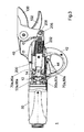
- the figure 1 illustrates a partially exploded view of an embodiment of the power tool 1 according to the invention, which in the example is an electric pruning shears.
- This pruner comprises in its rear part a hood 30 connected to the front part of the shears, composed of a shell 40 of metal, for example aluminum. Two outer plastic shells can cover the shell 40.
- the metal shell 40 serves to support a rotary actuator, not shown, which is housed in the rear cover 30 and which is blocked by means of a fixing sleeve 20 and a fixing ring 32
- One or more joints, for example O-Ring seals, can also be used in correspondence of the connection between the front part and the rear part of the pruner.
- the fixing sleeve 20 can be inserted above the rotary actuator in order to guarantee the mechanical strength of the actuator with respect to the cover 30.
- the rotary actuator may be a linear electric actuator comprising a motor-reduction unit.
- the reducer comprises for example a ring gear and unillustrated satellites.
- the power tool according to the invention comprises a ball nut 200 and a ball screw 202 on the nut 200 and having a first end 202a connected to the movable blade 100.
- the connection between the ball screw 202 and the movable blade is made using a fork 204 which cooperates with a first fastening element 206, for example a pivot, and a second fastening element, for example a circlip 208.
- a cardanic joint visible in the circle of the figure 1 and on the figure 2 , is arranged to be driven by the rotary actuator and to drive the ball nut 200 in rotation on the ball screw 202, so as to move the ball screw 202 and thus the movable member 100 relative to the fixed member 102.
- the cardanic joint is driven by the rotary actuator and causes the ball nut 200 to rotate on the ball screw 202: the ball nut therefore rotates on itself without moving. Its rotation advances the ball screw 202 which thus moves the movable blade 100 relative to the counterblade 102.
- the ball nut 200 is movable only in rotation
- the ball screw 202 is immobile in rotation and is displaced only in the axial direction, that is to say the direction corresponding to that of the length. of the power tool during the rotation of the ball nut 200.
- the ball screw 202 thus works only in tension or in compression.
- the cardanic joint is composed of an axis 10 and two cleats 12 which are inserted into the ends of the axis.
- the body of the shaft is inserted into a support member 16 cooperating with the geared motor or directly with the motor.
- the cleats rotate a fork 14 connected to the ball nut 200, for example inserted into the ball nut 200.
- cardanic joint can be imagined in the context of the invention, comprising for example two forks cooperating with each other by means of a connecting piece, for example in the form of a cross.
- the cardanic joint illustrated in the figures is maintained inside a first and a second connection of concentric ball-type of different or equal radii, allowing the recovery of bidirectional axial forces.
- a first convex bearing ring 50 has an outer spherical surface 50a which fits exactly to the inner spherical surface of a second bearing ring 60 which is concave and which is connected to the body of the tool.
- the two spherical surfaces 50a, 60a allow the transmission of the axial force generated by the rotary actuator to the ball nut 200 and constitute a first ball-type connection.
- a third support ring 70 which is convex, also has an outer spherical surface 70a which is concentric with the spherical surface 50a of the first support ring. This spherical surface fits a complementary spherical surface of a fourth ring 80, forming with the latter a second ball-type connection 70a, 80a, visible on the figures 3 and 4 concentric with the first link 50a, 60a.
- the third support ring 70 may comprise bearings 72.
- the system composed of the cardanic joint and the ball-type double connection allows an angularly variable rotation output.
- any radial force on the ball screw 202 is eliminated, which improves the service life of the tool compared to known solutions.
- the presence of a cardanic joint in a concentric double joint of ball-type thus makes it possible on the one hand to take up the forces of the rotary actuator and on the other hand to have an angularly variable output, as visible on the figures 3 and 4 .
- the forces of the rotary actuator are resumed close to the hand of the user: the distance between the point where the forces are resumed, that is to say the pivot point of the cardanic joint, and the movable blade 100 allows a better decomposition of forces compared to known solutions.
- the cardanic joint according to the invention is also homokinetic, that is to say that it drives the ball nut 200 in rotation on the ball screw 202 with the same speed by which it is driven by the rotary actuator.
- the movable element-ball screw connection incorporates an unillustrated scraper sleeve which prevents foreign bodies, dust or liquid drops from entering the power tool from the front to the back of the machine. 'tool.
- the scraper sleeve can be made of a high performance polymer having the required mechanical characteristics, having a low coefficient of friction, and preferably self-lubricating. Suitable materials for this application are, for example, Teflon® (PTFE), Polyethylene (PE), Polyethylene Terephthalate (PET), Polyethylene Terephthalate Polyester (PETP), Polyamide, or Delrin® (POM). This list is not exhaustive. It is also possible, however, to achieve the metal scraper sleeve, for example brass.
- the scraper sleeve may be a wear part, to be replaced when necessary, and may have on its front edge a lip to clean the inner surface of the body of the tool any dirt that may settle.
- protected volume delimited by the body of the power tool and the scraper sleeve houses a positioning system of the movable element, for example one or more permanent magnets, with respect to one or more position sensors, for example Hall effect sensors, magnetoresistive sensors, etc.
- a magnet support comprising for example one or more magnets, can be mounted on the ball nut and / or on the ball screw.
- the magnets can be of the same size and the same polarity.
- These magnets can interact with one or more position sensors placed on an integrated circuit 46 housed in the body of the power tool, to measure the rotation of the nut and / or the position of the ball screw to connect the number engine revolutions made and the rotation of the nut / ball screw position in case a sensorless technology is used to count the number of revolutions made by the engine.
Landscapes
- Engineering & Computer Science (AREA)
- Mechanical Engineering (AREA)
- Life Sciences & Earth Sciences (AREA)
- General Engineering & Computer Science (AREA)
- Forests & Forestry (AREA)
- Biodiversity & Conservation Biology (AREA)
- Ecology (AREA)
- Environmental Sciences (AREA)
- Scissors And Nippers (AREA)
- Transmission Devices (AREA)
Claims (15)
- Ein tragbares Elektrowerkzeug aufweisend- ein bewegliches Element (100) und ein festes Element (102)- einen rotierbaren Aktuator mit einer ersten Rotationsachse- eine Kugelmutter (200) aufweisend eine zweite Rotationsachse- eine Kugelschraube (202) aufweisend eine erste Extremität (202a) verbunden mit dem beweglichen Element (100),
wobei das Werkzeug gekennzeichnet dadurch gekennzeichnet ist, dass es auch aufweist:- ein Kardangelenk (10, 12, 14) ausgebildet von dem rotierbaren Aktuator angetrieben zu werden und die Kugelmutter (200) auf der Kugelschraube in Rotation zu bringen, um die Kugelschraube (202) und somit das bewegliche Element (100) relativ zu dem festen Element (102) zu bewegen. - Das tragbare Elektrowerkzeug nach Anspruch 1, aufweisend zwei sphärische Lager (50a, 60a; 70a, 80a), wobei das Kardangelenk (10, 12, 14) ausgebildet sit, zwischen die sphärischen Lager (50a, 60a; 70a, 80a) eingeführt zu werden.
- Das tragbare Elektrowerkzeug nach einem der Ansprüche 1 oder 2, wobei das Kardangelenk eine Achse (10), zwei Ausnehmungen (12) und eine Gabel (14) aufweist.
- Das tragbare Elektrowerkzeug nach Anspruch 3, wobei die Achse einen Körper und zwei Enden aufweist, wobei der Körper der Achse (10) ausgebildet ist, in ein Lagerelement (16) mit dem rotierbaren Aktuator kooperierend einzugreifen, wobei die Ausnehmungen (12) ausgebildet sind in die Enden der Achse eingeführt zu werden und die Gabel (14) in Rotation zu bringen.
- Das tragbare Elektrowerkzeug nach einem der Ansprüche 1 bis 4, aufweisend eine erste Verbindung eines Kugelgelenktyps.
- Das tragbare Elektrowerkzeug nach einem der Ansprüche 1 bis 5, aufweisend eine zweite Verbindung eines Kugelgelenktyps.
- Das tragbare Elektrowerkzeug nach Anspruch 6, wobei die zweite Verbindung des Kugelgelenktyps (70a, 80a) konzentrisch mit der ersten Verbindung des Kugelgelenktyps (50a, 60a) ist.
- Das tragbare Elektrowerkzeug nach einem der Ansprüche 1 bis 7, aufweisend eine Abschabhülse.
- Das tragbare Elektrowerkzeug nach einem der Ansprüche 1 bis 8, aufweisend ein Positionssystem des beweglichen Elements.
- Das tragbare Elektrowerkzeug nach einem der Ansprüche 1 bis 9, wobei die Kugelmutter (200) nur in Rotation beweglich ist, wobei die Kugelschraube (202) für Rotation unbeweglich ist und nur in der axialen Richtung auf eine Rotation der Kugelmutter (200) bewegbar ist.
- Das tragbare Elektrowerkzeug nach einem der Ansprüche 1 bis 10, wobei das erste Ende (202a) der Kugelschraube (202) mit dem beweglichen Element (100) direkt oder mittels einem Verbindungsteil, wie eine Gabel (204), verbunden ist.
- Das tragbare Elektrowerkzeug nach einem der Ansprüche 1 bis 11, wobei der rotierbare Aktuator ein linearer elektrischer Aktuator ist, der eine Gebtriebemotorgruppe aufweist, die auf das Kardangelenk (10, 12, 14) wirkt, die die Kugelmutter (200) in Rotation antreibt, die die Kugelschraube (202) in Translation bringt.
- Das tragbare Elektrowerkzeug nach einem der Ansprüche 1 bis 12, wobei das Kardangelenk (10, 12, 14) homokinetisch ist.
- Das tragbare Elektrowerkzeug nach einem der Ansprüche 1 bis 13 eine Baum- oder Heckenschere ausbildet.
- Ein Verfahren zum Übertragen von Kräften in einem tragbaren Elektrowerkzeug (1) mit einem beweglichen Element (100) und einem festen Element (102) aufweisend die folgenden Schritte:- Antreiben eines Kardangelenks (10, 12, 14) durch einen rotierbaren Aktuator;- Antreiben einer Kugelmutter (200) in Rotation auf einer Kugelschraube (202) durch das in zwei sphärische Lager (50a, 60a; 70a, 80a) eingesetzte Kardangelenk (10, 12, 14), wobei die Kugelschraube ein mit dem beweglichen Element (100) verbundenes Ende aufweist;- Bewegen der Kugelschraube (202) und somit des beweglichen Elements (100) relativ zu dem festen Element (102).
Priority Applications (4)
| Application Number | Priority Date | Filing Date | Title |
|---|---|---|---|
| EP12005023.2A EP2682238B1 (de) | 2012-07-06 | 2012-07-06 | Mobiles Elektroinstrument |
| US14/400,849 US9168667B2 (en) | 2012-07-06 | 2013-07-03 | Handheld power tool |
| PCT/EP2013/064039 WO2014006095A1 (fr) | 2012-07-06 | 2013-07-03 | Outil électroportatif |
| JP2015515553A JP5758060B2 (ja) | 2012-07-06 | 2013-07-03 | 手持式電動工具 |
Applications Claiming Priority (1)
| Application Number | Priority Date | Filing Date | Title |
|---|---|---|---|
| EP12005023.2A EP2682238B1 (de) | 2012-07-06 | 2012-07-06 | Mobiles Elektroinstrument |
Publications (2)
| Publication Number | Publication Date |
|---|---|
| EP2682238A1 EP2682238A1 (de) | 2014-01-08 |
| EP2682238B1 true EP2682238B1 (de) | 2015-05-27 |
Family
ID=48745966
Family Applications (1)
| Application Number | Title | Priority Date | Filing Date |
|---|---|---|---|
| EP12005023.2A Active EP2682238B1 (de) | 2012-07-06 | 2012-07-06 | Mobiles Elektroinstrument |
Country Status (4)
| Country | Link |
|---|---|
| US (1) | US9168667B2 (de) |
| EP (1) | EP2682238B1 (de) |
| JP (1) | JP5758060B2 (de) |
| WO (1) | WO2014006095A1 (de) |
Families Citing this family (19)
| Publication number | Priority date | Publication date | Assignee | Title |
|---|---|---|---|---|
| US8919787B1 (en) * | 2010-10-08 | 2014-12-30 | James Timothy Wilcher | Reciprocating tool attachment assembly and methods |
| EP2844057B1 (de) * | 2012-05-04 | 2016-04-27 | FELCO Motion SA | Handwerkzeugmaschine |
| EP2682238B1 (de) * | 2012-07-06 | 2015-05-27 | FELCO Motion SA | Mobiles Elektroinstrument |
| US9849524B2 (en) * | 2013-03-15 | 2017-12-26 | Creative Motion Control, Inc. | Tool with linear drive mechanism |
| FR3028717B1 (fr) * | 2014-11-25 | 2017-03-31 | Pellenc Sa | Outil electroportatif a transmission protegee. |
| CN104604545B (zh) * | 2015-02-12 | 2017-06-06 | 东莞市嘉航实业有限公司 | 电动修枝剪刀 |
| NL2014868B1 (nl) * | 2015-05-27 | 2017-01-02 | Jpm Beheer B V | Reddingsgereedschap. |
| JP6676905B2 (ja) * | 2015-09-14 | 2020-04-08 | マックス株式会社 | 電動はさみ |
| CN105340593A (zh) * | 2015-11-19 | 2016-02-24 | 张莉萍 | 一种新型电动修枝剪刀 |
| CN105917984A (zh) * | 2016-06-28 | 2016-09-07 | 东莞市嘉航实业有限公司 | 电动剪刀 |
| CN106305166A (zh) * | 2016-10-21 | 2017-01-11 | 方培锵 | 一种低枝剪 |
| US10512964B2 (en) | 2016-12-14 | 2019-12-24 | Ridge Tool Company | Electrically powered crimp tool |
| US10675805B2 (en) | 2016-12-14 | 2020-06-09 | Ridge Tool Company | Electrically powered crimp tool and method of using |
| CN108501046A (zh) * | 2018-05-18 | 2018-09-07 | 苏州速菲特农林工具有限公司 | 一种大剪力电动剪刀 |
| JP6695486B1 (ja) * | 2019-09-13 | 2020-05-20 | アルスコーポレーション株式会社 | 剪定用電動切断装置 |
| CN112514673A (zh) * | 2020-12-24 | 2021-03-19 | 东莞市嘉航实业有限公司 | 电剪刀刀片双向驱动机构及电动剪刀 |
| USD1000243S1 (en) * | 2021-07-09 | 2023-10-03 | Suzhou Ailixi Brushless Motor Co., Ltd. | Electric scissors |
| CN114654484B (zh) * | 2022-02-28 | 2024-03-29 | 哈尔滨工业大学 | 一种适用于大温差和剪口防逃逸设计的剪刀工具 |
| USD1003137S1 (en) * | 2022-03-25 | 2023-10-31 | Innovation Fabrication Commercialisation Infaco | Hedge trimmer |
Family Cites Families (25)
| Publication number | Priority date | Publication date | Assignee | Title |
|---|---|---|---|---|
| US1553312A (en) * | 1922-04-27 | 1925-09-15 | Western Electric Co | Universal joint |
| FR846943A (fr) * | 1937-12-02 | 1939-09-28 | Audi Ag | Joint à cardan |
| US2927444A (en) * | 1957-01-28 | 1960-03-08 | Wildhaber Ernest | Universal joint |
| US3609994A (en) * | 1969-10-01 | 1971-10-05 | Trw Inc | Universal joint |
| US4395246A (en) * | 1980-09-05 | 1983-07-26 | The Bendix Corporation | Universal joint |
| FR2624417B1 (fr) | 1987-04-28 | 1994-06-10 | Pellenc & Motte | Outil electrique portable |
| DE8814543U1 (de) * | 1988-11-22 | 1989-01-19 | Niko Nippert Maschinenbau, 7580 Buehl, De | |
| US5816926A (en) * | 1997-06-03 | 1998-10-06 | The Torrington Company | Ball and socket double cardan motion universal joint |
| CA2490102C (en) * | 2004-12-13 | 2013-08-13 | Pii (Canada) Limited | Hollow universal joint |
| AT501590B1 (de) | 2005-11-25 | 2006-10-15 | Strube Karl | Elektrische schere |
| FR2913949B1 (fr) * | 2007-03-23 | 2009-10-02 | Goodrich Actuation Systems Sas | Perfectionnements a la detection de la reprise d'effort de la voie secondaire d'un actionneur de commande de vol. |
| US7527500B2 (en) * | 2007-06-14 | 2009-05-05 | John Mezza Lingua Associates, Inc. | Swivel wall port for coaxial cable |
| FR2935175B1 (fr) * | 2008-08-22 | 2011-02-11 | Pellenc Sa | Dispositif permettant de determiner la position relative entre deux organes dont l'un au moins est mobile, et machines et appareils en faisant application |
| JP5272758B2 (ja) | 2009-01-30 | 2013-08-28 | マックス株式会社 | 電動工具 |
| JP5332662B2 (ja) * | 2009-01-30 | 2013-11-06 | マックス株式会社 | 電動はさみ |
| KR101132328B1 (ko) * | 2009-03-23 | 2012-04-05 | 로아텍 주식회사 | 방아쇠가 구비된 전동 전지가위 |
| AT508243B1 (de) | 2009-06-25 | 2010-12-15 | Lunatone Ind Elektronik Gmbh | Elektrische schere |
| AT509087B1 (de) | 2009-11-17 | 2011-09-15 | Lunatone Ind Elektronik Gmbh | Schere |
| TWI376296B (en) * | 2010-03-19 | 2012-11-11 | Cheng Wei Su | Tool joint structure |
| US9080611B2 (en) * | 2010-12-01 | 2015-07-14 | Howmedica Osteonics Corp. | Drive tool having an angled connector |
| FR2978079B1 (fr) * | 2011-07-19 | 2013-07-12 | Mage Applic | Outil electromecanique portatif |
| EP2844057B1 (de) * | 2012-05-04 | 2016-04-27 | FELCO Motion SA | Handwerkzeugmaschine |
| EP2682238B1 (de) * | 2012-07-06 | 2015-05-27 | FELCO Motion SA | Mobiles Elektroinstrument |
| DE102012024838A1 (de) * | 2012-12-19 | 2014-06-26 | Andreas Stihl Ag & Co. Kg | Elektrische Schere |
| US20150096397A1 (en) * | 2013-10-07 | 2015-04-09 | National Chung Cheng University | Ball screw capable of sensing torque in real time |
-
2012
- 2012-07-06 EP EP12005023.2A patent/EP2682238B1/de active Active
-
2013
- 2013-07-03 US US14/400,849 patent/US9168667B2/en not_active Expired - Fee Related
- 2013-07-03 JP JP2015515553A patent/JP5758060B2/ja not_active Expired - Fee Related
- 2013-07-03 WO PCT/EP2013/064039 patent/WO2014006095A1/fr active Application Filing
Also Published As
| Publication number | Publication date |
|---|---|
| US9168667B2 (en) | 2015-10-27 |
| JP2015521091A (ja) | 2015-07-27 |
| WO2014006095A1 (fr) | 2014-01-09 |
| US20150121706A1 (en) | 2015-05-07 |
| JP5758060B2 (ja) | 2015-08-05 |
| EP2682238A1 (de) | 2014-01-08 |
Similar Documents
| Publication | Publication Date | Title |
|---|---|---|
| EP2682238B1 (de) | Mobiles Elektroinstrument | |
| EP2844057B1 (de) | Handwerkzeugmaschine | |
| EP3223599B1 (de) | Handwerkzeugmaschine mit geschütztem getriebe | |
| EP2864167A1 (de) | Elektrischer bremskraftverstärker mit getriebespielausgleich | |
| FR2458433A1 (fr) | Dispositif d'actionnement d'un embrayage a disques de vehicule automobile, en particulier de camion | |
| FR2544422A1 (fr) | Dispositif d'accouplement a petit debattement pour arbres oscillants | |
| FR2822916A1 (fr) | Boitier d'un mecanisme de transmission | |
| FR2800818A1 (fr) | Dispositif protecteur pour un train d'entrainement comprenant un joint a croisillon double | |
| CA2480210A1 (fr) | Actionneur a deux modes de fonctionnement | |
| FR2739153A1 (fr) | Articulation elastique, en particulier pour suspension d'un vehicule automobile | |
| FR2940773A1 (fr) | Dispositif de transmission pour engin roulant automoteur | |
| CH696392A5 (fr) | Tête de coupe pour ciseaux motorisés. | |
| FR3065763B1 (fr) | Maneton de bielle pour un systeme de tringlerie d’actionnement d’essuie-glaces et son procede d’assemblage | |
| EP1899117B1 (de) | Mit mehreren entfernbaren köpfen versehene rasier-, schneid-, epilier- und/oder exfoliationsvorrichtung | |
| EP2786845A1 (de) | Mobiles Elektroinstrument | |
| FR2972662A1 (fr) | Outil pour le serrage et/ou le desserrage d'un assemblage a vis et ecrou et procede d'assemblage le mettant en oeuvre | |
| WO2016008917A1 (fr) | Gamme de dispositifs d'accouplement | |
| FR3018756B1 (fr) | Dispositif d'entrainement de dispositif d'essuie-glace | |
| EP0333539B1 (de) | Lösbarer Linearschrittmotor mit einem rückzentrierten Läufer | |
| FR3069507A1 (fr) | Ensemble maneton-manivelle d'un mecanisme de transmission de mouvement d'un systeme d'essuie-glace | |
| EP1878946B1 (de) | Mechanismus zum Drehantrieb einer Last um zwei Achsen | |
| FR3042242A3 (fr) | Dispositif d'accouplement pour l'entrainement en rotation de deux arbres a axes non alignes mais concourants | |
| FR3112744A1 (fr) | Boîtier de transmission et engin roulant équipé d’un tel boîtier de transmission | |
| FR3033680A1 (fr) | Faucheuse debroussailleuse avec au moins un bras articule et un outil de coupe relie a l'extremite libre du bras par un verin rotatif | |
| FR2742727A1 (fr) | Dispositif d'accouplement coaxial entre deux arbres, notamment pour helicoptere |
Legal Events
| Date | Code | Title | Description |
|---|---|---|---|
| PUAI | Public reference made under article 153(3) epc to a published international application that has entered the european phase |
Free format text: ORIGINAL CODE: 0009012 |
|
| AK | Designated contracting states |
Kind code of ref document: A1 Designated state(s): AL AT BE BG CH CY CZ DE DK EE ES FI FR GB GR HR HU IE IS IT LI LT LU LV MC MK MT NL NO PL PT RO RS SE SI SK SM TR |
|
| AX | Request for extension of the european patent |
Extension state: BA ME |
|
| RBV | Designated contracting states (corrected) |
Designated state(s): AL AT BE BG CH CY CZ DE DK EE ES FI FR GB GR HR HU IE IS IT LI LT LU LV MC MK MT NL NO PL PT RO RS SE SI SK SM TR |
|
| 17P | Request for examination filed |
Effective date: 20140703 |
|
| GRAP | Despatch of communication of intention to grant a patent |
Free format text: ORIGINAL CODE: EPIDOSNIGR1 |
|
| INTG | Intention to grant announced |
Effective date: 20150107 |
|
| GRAS | Grant fee paid |
Free format text: ORIGINAL CODE: EPIDOSNIGR3 |
|
| GRAA | (expected) grant |
Free format text: ORIGINAL CODE: 0009210 |
|
| AK | Designated contracting states |
Kind code of ref document: B1 Designated state(s): AL AT BE BG CH CY CZ DE DK EE ES FI FR GB GR HR HU IE IS IT LI LT LU LV MC MK MT NL NO PL PT RO RS SE SI SK SM TR |
|
| REG | Reference to a national code |
Ref country code: GB Ref legal event code: FG4D Free format text: NOT ENGLISH |
|
| REG | Reference to a national code |
Ref country code: CH Ref legal event code: EP |
|
| REG | Reference to a national code |
Ref country code: AT Ref legal event code: REF Ref document number: 728583 Country of ref document: AT Kind code of ref document: T Effective date: 20150615 Ref country code: CH Ref legal event code: NV Representative=s name: P&TS SA, CH |
|
| REG | Reference to a national code |
Ref country code: FR Ref legal event code: PLFP Year of fee payment: 4 |
|
| REG | Reference to a national code |
Ref country code: IE Ref legal event code: FG4D Free format text: LANGUAGE OF EP DOCUMENT: FRENCH |
|
| REG | Reference to a national code |
Ref country code: DE Ref legal event code: R096 Ref document number: 602012007491 Country of ref document: DE Effective date: 20150709 |
|
| REG | Reference to a national code |
Ref country code: AT Ref legal event code: MK05 Ref document number: 728583 Country of ref document: AT Kind code of ref document: T Effective date: 20150527 |
|
| REG | Reference to a national code |
Ref country code: LT Ref legal event code: MG4D |
|
| PG25 | Lapsed in a contracting state [announced via postgrant information from national office to epo] |
Ref country code: PT Free format text: LAPSE BECAUSE OF FAILURE TO SUBMIT A TRANSLATION OF THE DESCRIPTION OR TO PAY THE FEE WITHIN THE PRESCRIBED TIME-LIMIT Effective date: 20150928 Ref country code: LT Free format text: LAPSE BECAUSE OF FAILURE TO SUBMIT A TRANSLATION OF THE DESCRIPTION OR TO PAY THE FEE WITHIN THE PRESCRIBED TIME-LIMIT Effective date: 20150527 Ref country code: ES Free format text: LAPSE BECAUSE OF FAILURE TO SUBMIT A TRANSLATION OF THE DESCRIPTION OR TO PAY THE FEE WITHIN THE PRESCRIBED TIME-LIMIT Effective date: 20150527 Ref country code: HR Free format text: LAPSE BECAUSE OF FAILURE TO SUBMIT A TRANSLATION OF THE DESCRIPTION OR TO PAY THE FEE WITHIN THE PRESCRIBED TIME-LIMIT Effective date: 20150527 Ref country code: NO Free format text: LAPSE BECAUSE OF FAILURE TO SUBMIT A TRANSLATION OF THE DESCRIPTION OR TO PAY THE FEE WITHIN THE PRESCRIBED TIME-LIMIT Effective date: 20150827 Ref country code: FI Free format text: LAPSE BECAUSE OF FAILURE TO SUBMIT A TRANSLATION OF THE DESCRIPTION OR TO PAY THE FEE WITHIN THE PRESCRIBED TIME-LIMIT Effective date: 20150527 |
|
| REG | Reference to a national code |
Ref country code: NL Ref legal event code: MP Effective date: 20150527 |
|
| PG25 | Lapsed in a contracting state [announced via postgrant information from national office to epo] |
Ref country code: BG Free format text: LAPSE BECAUSE OF FAILURE TO SUBMIT A TRANSLATION OF THE DESCRIPTION OR TO PAY THE FEE WITHIN THE PRESCRIBED TIME-LIMIT Effective date: 20150827 Ref country code: RS Free format text: LAPSE BECAUSE OF FAILURE TO SUBMIT A TRANSLATION OF THE DESCRIPTION OR TO PAY THE FEE WITHIN THE PRESCRIBED TIME-LIMIT Effective date: 20150527 Ref country code: LV Free format text: LAPSE BECAUSE OF FAILURE TO SUBMIT A TRANSLATION OF THE DESCRIPTION OR TO PAY THE FEE WITHIN THE PRESCRIBED TIME-LIMIT Effective date: 20150527 Ref country code: IS Free format text: LAPSE BECAUSE OF FAILURE TO SUBMIT A TRANSLATION OF THE DESCRIPTION OR TO PAY THE FEE WITHIN THE PRESCRIBED TIME-LIMIT Effective date: 20150927 Ref country code: GR Free format text: LAPSE BECAUSE OF FAILURE TO SUBMIT A TRANSLATION OF THE DESCRIPTION OR TO PAY THE FEE WITHIN THE PRESCRIBED TIME-LIMIT Effective date: 20150828 Ref country code: AT Free format text: LAPSE BECAUSE OF FAILURE TO SUBMIT A TRANSLATION OF THE DESCRIPTION OR TO PAY THE FEE WITHIN THE PRESCRIBED TIME-LIMIT Effective date: 20150527 |
|
| PG25 | Lapsed in a contracting state [announced via postgrant information from national office to epo] |
Ref country code: EE Free format text: LAPSE BECAUSE OF FAILURE TO SUBMIT A TRANSLATION OF THE DESCRIPTION OR TO PAY THE FEE WITHIN THE PRESCRIBED TIME-LIMIT Effective date: 20150527 Ref country code: DK Free format text: LAPSE BECAUSE OF FAILURE TO SUBMIT A TRANSLATION OF THE DESCRIPTION OR TO PAY THE FEE WITHIN THE PRESCRIBED TIME-LIMIT Effective date: 20150527 |
|
| PG25 | Lapsed in a contracting state [announced via postgrant information from national office to epo] |
Ref country code: RO Free format text: LAPSE BECAUSE OF NON-PAYMENT OF DUE FEES Effective date: 20150527 Ref country code: SK Free format text: LAPSE BECAUSE OF FAILURE TO SUBMIT A TRANSLATION OF THE DESCRIPTION OR TO PAY THE FEE WITHIN THE PRESCRIBED TIME-LIMIT Effective date: 20150527 Ref country code: CZ Free format text: LAPSE BECAUSE OF FAILURE TO SUBMIT A TRANSLATION OF THE DESCRIPTION OR TO PAY THE FEE WITHIN THE PRESCRIBED TIME-LIMIT Effective date: 20150527 Ref country code: MC Free format text: LAPSE BECAUSE OF FAILURE TO SUBMIT A TRANSLATION OF THE DESCRIPTION OR TO PAY THE FEE WITHIN THE PRESCRIBED TIME-LIMIT Effective date: 20150527 Ref country code: PL Free format text: LAPSE BECAUSE OF FAILURE TO SUBMIT A TRANSLATION OF THE DESCRIPTION OR TO PAY THE FEE WITHIN THE PRESCRIBED TIME-LIMIT Effective date: 20150527 |
|
| REG | Reference to a national code |
Ref country code: DE Ref legal event code: R097 Ref document number: 602012007491 Country of ref document: DE |
|
| PG25 | Lapsed in a contracting state [announced via postgrant information from national office to epo] |
Ref country code: LU Free format text: LAPSE BECAUSE OF FAILURE TO SUBMIT A TRANSLATION OF THE DESCRIPTION OR TO PAY THE FEE WITHIN THE PRESCRIBED TIME-LIMIT Effective date: 20150706 |
|
| PLBE | No opposition filed within time limit |
Free format text: ORIGINAL CODE: 0009261 |
|
| STAA | Information on the status of an ep patent application or granted ep patent |
Free format text: STATUS: NO OPPOSITION FILED WITHIN TIME LIMIT |
|
| REG | Reference to a national code |
Ref country code: IE Ref legal event code: MM4A |
|
| 26N | No opposition filed |
Effective date: 20160301 |
|
| PG25 | Lapsed in a contracting state [announced via postgrant information from national office to epo] |
Ref country code: SI Free format text: LAPSE BECAUSE OF FAILURE TO SUBMIT A TRANSLATION OF THE DESCRIPTION OR TO PAY THE FEE WITHIN THE PRESCRIBED TIME-LIMIT Effective date: 20150527 |
|
| REG | Reference to a national code |
Ref country code: FR Ref legal event code: PLFP Year of fee payment: 5 |
|
| PG25 | Lapsed in a contracting state [announced via postgrant information from national office to epo] |
Ref country code: IE Free format text: LAPSE BECAUSE OF NON-PAYMENT OF DUE FEES Effective date: 20150706 |
|
| GBPC | Gb: european patent ceased through non-payment of renewal fee |
Effective date: 20160706 |
|
| PG25 | Lapsed in a contracting state [announced via postgrant information from national office to epo] |
Ref country code: MT Free format text: LAPSE BECAUSE OF FAILURE TO SUBMIT A TRANSLATION OF THE DESCRIPTION OR TO PAY THE FEE WITHIN THE PRESCRIBED TIME-LIMIT Effective date: 20150527 |
|
| PG25 | Lapsed in a contracting state [announced via postgrant information from national office to epo] |
Ref country code: HU Free format text: LAPSE BECAUSE OF FAILURE TO SUBMIT A TRANSLATION OF THE DESCRIPTION OR TO PAY THE FEE WITHIN THE PRESCRIBED TIME-LIMIT; INVALID AB INITIO Effective date: 20120706 Ref country code: SM Free format text: LAPSE BECAUSE OF FAILURE TO SUBMIT A TRANSLATION OF THE DESCRIPTION OR TO PAY THE FEE WITHIN THE PRESCRIBED TIME-LIMIT Effective date: 20150527 Ref country code: GB Free format text: LAPSE BECAUSE OF NON-PAYMENT OF DUE FEES Effective date: 20160706 |
|
| PG25 | Lapsed in a contracting state [announced via postgrant information from national office to epo] |
Ref country code: SE Free format text: LAPSE BECAUSE OF FAILURE TO SUBMIT A TRANSLATION OF THE DESCRIPTION OR TO PAY THE FEE WITHIN THE PRESCRIBED TIME-LIMIT Effective date: 20150527 Ref country code: CY Free format text: LAPSE BECAUSE OF FAILURE TO SUBMIT A TRANSLATION OF THE DESCRIPTION OR TO PAY THE FEE WITHIN THE PRESCRIBED TIME-LIMIT Effective date: 20150527 Ref country code: NL Free format text: LAPSE BECAUSE OF FAILURE TO SUBMIT A TRANSLATION OF THE DESCRIPTION OR TO PAY THE FEE WITHIN THE PRESCRIBED TIME-LIMIT Effective date: 20150527 |
|
| REG | Reference to a national code |
Ref country code: FR Ref legal event code: PLFP Year of fee payment: 6 |
|
| PG25 | Lapsed in a contracting state [announced via postgrant information from national office to epo] |
Ref country code: BE Free format text: LAPSE BECAUSE OF NON-PAYMENT OF DUE FEES Effective date: 20150731 |
|
| PG25 | Lapsed in a contracting state [announced via postgrant information from national office to epo] |
Ref country code: MK Free format text: LAPSE BECAUSE OF FAILURE TO SUBMIT A TRANSLATION OF THE DESCRIPTION OR TO PAY THE FEE WITHIN THE PRESCRIBED TIME-LIMIT Effective date: 20150527 Ref country code: TR Free format text: LAPSE BECAUSE OF FAILURE TO SUBMIT A TRANSLATION OF THE DESCRIPTION OR TO PAY THE FEE WITHIN THE PRESCRIBED TIME-LIMIT Effective date: 20150527 |
|
| REG | Reference to a national code |
Ref country code: FR Ref legal event code: PLFP Year of fee payment: 7 |
|
| PG25 | Lapsed in a contracting state [announced via postgrant information from national office to epo] |
Ref country code: AL Free format text: LAPSE BECAUSE OF FAILURE TO SUBMIT A TRANSLATION OF THE DESCRIPTION OR TO PAY THE FEE WITHIN THE PRESCRIBED TIME-LIMIT Effective date: 20150527 |
|
| REG | Reference to a national code |
Ref country code: DE Ref legal event code: R082 Ref document number: 602012007491 Country of ref document: DE Representative=s name: BECK & ROESSIG EUROPEAN PATENT ATTORNEYS, DE Ref country code: DE Ref legal event code: R082 Ref document number: 602012007491 Country of ref document: DE Representative=s name: BECK & ROESSIG - EUROPEAN PATENT ATTORNEYS, DE |
|
| REG | Reference to a national code |
Ref country code: DE Ref legal event code: R081 Ref document number: 602012007491 Country of ref document: DE Owner name: FELCO SA, CH Free format text: FORMER OWNER: FELCO MOTION SA, LES GENEVEYS-SUR-COFFRANE, CH Ref country code: DE Ref legal event code: R082 Ref document number: 602012007491 Country of ref document: DE Representative=s name: BECK & ROESSIG - EUROPEAN PATENT ATTORNEYS, DE |
|
| REG | Reference to a national code |
Ref country code: CH Ref legal event code: PFUS Owner name: FELCO SA, CH Free format text: FORMER OWNER: FELCO MOTION SA, CH |
|
| PGFP | Annual fee paid to national office [announced via postgrant information from national office to epo] |
Ref country code: IT Payment date: 20230724 Year of fee payment: 12 Ref country code: CH Payment date: 20230801 Year of fee payment: 12 |
|
| PGFP | Annual fee paid to national office [announced via postgrant information from national office to epo] |
Ref country code: FR Payment date: 20230725 Year of fee payment: 12 Ref country code: DE Payment date: 20230719 Year of fee payment: 12 |