EP0333539B1 - Lösbarer Linearschrittmotor mit einem rückzentrierten Läufer - Google Patents
Lösbarer Linearschrittmotor mit einem rückzentrierten Läufer Download PDFInfo
- Publication number
- EP0333539B1 EP0333539B1 EP89400536A EP89400536A EP0333539B1 EP 0333539 B1 EP0333539 B1 EP 0333539B1 EP 89400536 A EP89400536 A EP 89400536A EP 89400536 A EP89400536 A EP 89400536A EP 0333539 B1 EP0333539 B1 EP 0333539B1
- Authority
- EP
- European Patent Office
- Prior art keywords
- rotor
- rod
- motor
- stator
- bore
- Prior art date
- Legal status (The legal status is an assumption and is not a legal conclusion. Google has not performed a legal analysis and makes no representation as to the accuracy of the status listed.)
- Expired - Lifetime
Links
- 230000003247 decreasing effect Effects 0.000 claims description 3
- 230000003100 immobilizing effect Effects 0.000 claims description 2
- 238000005096 rolling process Methods 0.000 claims description 2
- 239000012858 resilient material Substances 0.000 claims 1
- 230000005284 excitation Effects 0.000 description 6
- 238000006073 displacement reaction Methods 0.000 description 3
- 239000013013 elastic material Substances 0.000 description 3
- 230000006835 compression Effects 0.000 description 2
- 238000007906 compression Methods 0.000 description 2
- 230000000694 effects Effects 0.000 description 2
- 230000008878 coupling Effects 0.000 description 1
- 238000010168 coupling process Methods 0.000 description 1
- 238000005859 coupling reaction Methods 0.000 description 1
- 230000005405 multipole Effects 0.000 description 1
- 210000000056 organ Anatomy 0.000 description 1
- 230000001105 regulatory effect Effects 0.000 description 1
- 238000010079 rubber tapping Methods 0.000 description 1
Images


Classifications
-
- H—ELECTRICITY
- H02—GENERATION; CONVERSION OR DISTRIBUTION OF ELECTRIC POWER
- H02K—DYNAMO-ELECTRIC MACHINES
- H02K7/00—Arrangements for handling mechanical energy structurally associated with dynamo-electric machines, e.g. structural association with mechanical driving motors or auxiliary dynamo-electric machines
- H02K7/06—Means for converting reciprocating motion into rotary motion or vice versa
-
- H—ELECTRICITY
- H02—GENERATION; CONVERSION OR DISTRIBUTION OF ELECTRIC POWER
- H02K—DYNAMO-ELECTRIC MACHINES
- H02K41/00—Propulsion systems in which a rigid body is moved along a path due to dynamo-electric interaction between the body and a magnetic field travelling along the path
- H02K41/06—Rolling motors, i.e. motors having the rotor axis parallel to the stator axis and following a circular path as the rotor rolls around the inside or outside of the stator ; Nutating motors, i.e. having the rotor axis parallel to the stator axis inclined with respect to the stator axis and performing a nutational movement as the rotor rolls on the stator
Definitions
- the subject of the present invention is a linear stepping electric motor comprising a multipolar stator provided with a threaded bore, a rotor of diameter smaller than that of said bore, threaded at the same pitch as said bore and rolling cycloidally inside. of the latter under the action of stator forces, and a drive rod axially integral with said rotor and thus driven in linear translation.
- Such a motor is used, for example, in precision regulation systems.
- the driving rod which moves linearly and step by step, controls the regulating organs. It is often called a control rod.
- a motor of this type is already known, described in European patent EP-A-0 078 740.
- the threads of the rotor are, most often, parallel grooves, at the same pitch as the threads of the stator, which are then helical and obtained by tapping the stator bore. The rotational movement of the rotor is thus transformed into linear movement.
- the rotor When the stator coils are successively excited, the rotor, under the action of the stator forces, turns according to angular steps, the number of which, over 360 °, is defined by the number of poles of the stator. Each revolution of the rotor thus corresponds to an axial advance corresponding to the pitch of the stator.
- the rotor being driven by a cycloidal movement, the driving rod, or control rod, is driven by a movement which makes its axis describe a circular cylinder.
- the control rod is connected to the member to be controlled by a double articulation, or it comprises an intermediate flexible part.
- GB-A-1 246 444 describes various means for transmitting the rotational movement of the rotor to the output shaft, means which accommodate the cycloidal movement of the rotor while the axis of the output shaft remains fixed. These means are, for example, joints with gimbals, bellows or even eccentric cams.
- US-A-3,512,019 describes a flexible ring which transmits the movement of the rotor, the axis of which here describes a cone, to the output shaft.
- application FR-A-2 492 605 describes discs made of elastic material which, in addition to their function of transmitting the movement of the rotor to the output shaft, have the function of maintaining, even at rest, a generator of the rotor in contact with a generator of the stator bore.
- French patent FR-A-1 317 985 describes an elastic articulated coupling which accommodates the cycloidal movement of the rotor, cycloidal movement of variable amplitude here, to cause a variation in the speed of rotation of the output shaft. .
- the present invention aims, for its part, to eliminate this drawback by providing in particular a linear stepping motor whose declutching is frank, in order to reduce wear and noise.
- a linear stepping motor of the type defined above, characterized in that said rod is rigid, and means are provided for immobilizing it radially at the center of said bore, as well as elastic means for refocusing to center said rotor on said rod in the absence of stator forces.
- the rotor is refocused on the drive rod by the elastic refocusing means.
- the driving rod is rigid and itself immobilized radially in the center of the bore
- the rotor is perfectly in the center of the bore, which certainly disengages its threads from those of the bore, and allows the return of the 'assembly comprising rod and rotor in its rest position without wear and noise.
- the elastic centering return means of the rotor on the rod do not have to transmit the rotational movement of the rotor to the rod, the latter being generally, and moreover, immobilized in rotation on it -even. No constraint is imposed on them with regard to torsional strength. By cons, they must effectively recall the rotor on the rod so that it is perfectly centered as soon as the stator excitation ceases.
- said rotor is a hollow cylinder with an inner diameter greater than that of said rod and traversed by it, and said elastic centering return means comprise at least two rings of elastic material arranged at a distance one on the other between said rod and said rotor.
- Such an embodiment is very simple and of a low cost price.
- said rotor is a hollow cylinder with a diameter greater than that of said rod and traversed by said rod
- said elastic centering return means comprise two sleeves of axially decreasing section, slidably mounted on said rod and resiliently and axially biased against two annular surfaces integral with the two ends of said rotor.
- This embodiment is particularly robust.
- the sleeves can be conical, or hemispherical. In the latter case, the return of the rotor to the rod is particularly effective, while allowing easy eccentric movement.
- said annular surfaces are conical.
- said sleeves are disposed outside of said rotor and they are elastically and axially returned by a single spring which moreover recalls, in the absence of stator forces, the assembly comprising said rod and said rotor in one of the two extreme positions of its range of possible axial positions.
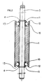
- a motor comprises a multipole stator 2 provided with a threaded bore 205, each pole being surrounded by a coil 201.
- a drive rod, or control rod, 3 is mounted movable in translation along the axis of the stator 2 and immobilized radially at the center of the bore of the stator 2 by bearings 6.
- the inside diameter of the rotor 1 is greater than the outside diameter of the control rod 3.
- each of the two ends 12 of the rotor 1 has a countersink 13.
- a ring 11 of internal diameter corresponding substantially to the external diameter of the control rod 3, and whose axial dimension is substantially equal to the depth of the counterbore in order to cooperate by pressing on the bottom of said counterbore.
- the outer periphery of each ring 11 has a groove profile, this groove receives an O-ring 10 of elastic material whose external diameter corresponds substantially to the diameter of the countersink 13 and bears on the cylindrical surface of the latter.
- the two O-rings 10 are thus arranged at a distance from each other.
- each ring 11 is such that it is less than the half-difference between the diameter of the countersink 13 and the internal diameter of the rotor 1 and is greater than the difference between the internal diameter of the rotor 1 and that of the rod 3; in this way the rotor 1 can be driven in a radial movement relative to the rod 3 and whatever the amplitude of this movement the rings 11 cooperate in abutment in the bottom of the counterbores 13.
- Two elastic rings 4 each mounted by clipping into a groove in the control rod 3 cooperate on either side of the rotor assembly 1, rings 11 and O-rings 10 so as to make it axially integral with the control rod 3.
- This cycloidal movement is accompanied by the compression of the O-rings 10: when the rotor 1 is attracted radially towards the excited stator pole, the portion of the O-rings 10 diametrically opposite to said pole is compressed and allows the rotor 1 to cooperate with the stator 2 by mutual engagement of their respective threads in the vicinity of the excited stator pole.
- the rotor 1 When the stator excitation stops, the rotor 1 is returned by the O-rings 10 in the position where it is centered on the rod 3, and where its axis coincides with that of the bore 205 of the stator 2. The rotor 1 and bore 205 threads no longer cooperate. The motor is thus disengaged.
- the elastic O-rings 10 recall the rotor 1 to center it on the rod 3 in the absence of stator forces.
- the spring 5 recalls the assembly comprising the rod 3 and the rotor 1 in their rest position, which corresponds to one of the two extreme positions of the range of possible axial positions of this assembly relative to the stator.
- the rest position corresponds to that where the rod 3 is extended as far as possible from the bore of the stator.
- another arrangement of the spring 5 would make it possible to have a rest position corresponding to the retracted rod 3. It is also possible, in certain applications, to remove the spring 5 so that the rod remains, in the absence of excitation, at the place where it is at the time of the cessation of the excitation, rather than returning systematically to the same rest position.
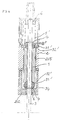
- the centering of the rotor 1 relative to the control rod 3 which passes through it is produced by two conical sleeves 31 mounted to slide around the rod control 3 and connected together by a helical spring 30 mounted coaxially around the control rod 3.
- Each of the two conical sleeves 31 is thus elastically and axially biased against an annular surface, here also conical, of a sleeve 32 integral with each of the ends of the rotor 1.
- Each sleeve 32 is provided with a shoulder 33 and fitted into each of the counterbores 13.
- each socket 32 is held in abutment against each flat end of the rotor 1 by a washer 34 interposed between said socket and an elastic ring 4 secured to the control rod 3.
- the thickness of each washer 34 is such that the rotor 1 is made longitudinally integral with the rod 3.
- the diameter of the bore of the sockets 32 is greater than that of the control rod 3 so as to allow a radial displacement of the rotor 1 capable of making it cooperate with the bore of the stator 2.
- FIG. 4 is shown an alternative embodiment of the assembly shown in Figure 3.
- the conical sleeves 31 are replaced by hemispherical sleeves 31 ′ which are arranged outside the rotor 1, on both sides other of it.
- Each of the sleeves 31 ′ is biased against two annular surfaces 32 ′, carried by the ends of the rotor 1 and here conical, by a helical spring 5 ′ mounted coaxially around the upper part, in FIG. 4, of the rod 3.
- the spring 5 ′ is supported on the one hand on the rear part of the motor housing, represented on the upper part of FIG. 4 and on the other hand on the upper sleeve 31 ′, in FIG. 4.
- the spring 5 ′ pushes the hemispherical sleeve 31 ′ upper against the conical annular surface 32 ′ of the rotor, which has the effect to refocus the rotor 1 on the rod 3, a similar phenomenon occurs between the hemispherical sleeve 31 ′ lower and the corresponding annular surface 32 ′.
- the threads of the rotor 1 and the bore of the stator 2 are released, and the spring 5 ′ then pushes the assembly comprising the rod 3 and the rotor 1 to the rest position where the rod is extended, position shown in the figure 4.
- the spring 5 ′ in addition to its function of refocusing the rotor 1, by means of the sleeves 31 ′, has the function of the spring 5 of FIG. 1, which can in this case be eliminated.
- the present invention is not limited to the conical sleeves 31 or hemispherical 31 'which have just been described by way of example.
- these sleeves are of axially decreasing section, and that their ends of small section are biased elastically against the annular surfaces such as 32 and 32 ′ integral with the ends of the rotor 1
- these annular surfaces 32 and 32 ′ be conical, these being able to have any suitable shape to favor sliding against the sliding sleeves 31 or 31 ′.
Landscapes
- Engineering & Computer Science (AREA)
- Power Engineering (AREA)
- Physics & Mathematics (AREA)
- Chemical & Material Sciences (AREA)
- Combustion & Propulsion (AREA)
- Electromagnetism (AREA)
- Connection Of Motors, Electrical Generators, Mechanical Devices, And The Like (AREA)
Claims (7)
- Linearschrittmotor umfassend einen mehrpoligen Ständer (2) mit einer Gewindebohrung (205), einen Läufer (1), dessen Durchmesser kleiner als der der besagten Bohrung ist, der die gleiche Gewindesteigung wie die besagte Bohrung (205) aufweist und der in dieser in zykloider Weise unter dem Einfluß vom Ständer her wirkender Kräfte rotiert, und einen Antriebsschaft (3), welcher axial mit dem besagten Läufer (1) fest verbunden ist und dadurch linear angetrieben wird, Motor dadurch gekennzeichnet, daß der besagte Schaft (3) starr ist und Mittel (6) vorgesehen sind, um ihn radial in der Mitte der besagten Bohrung (205) zu fixieren, sowie elastische Rückstell-Rückzentrierungsmittel (10; 30, 31, 32; 5′, 31′, 32′), um den besagten Läufer (1) mangels vom Ständer her wirkender Kräfte auf dem besagten Schaft (3) zu zentrieren.
- Motor gemäß Anspruch 1, bei welchem der besagte Läufer (1) ein hohler Zylinder ist, dessen Innendurchmesser größer als der des besagten , durch ihn hindurchgehenden Schaftes (3) ist, und bei welchem die besagten elastischen Rückstell-Rückzentrierungsmittel mindestens zwei Ringe (10) aus elastischem Material umfassen, die in einem Abstand voneinander zwischen dem besagten Schaft (3) und dem besagten Läufer (1) angeordnet sind.
- Motor gemäß Anspruch 1, bei welchem der besagte Läufer (1) ein hohler Zylinder ist, dessen Durchmesser größer als der des besagten, durch ihn hindurchgehenden Schaftes (3) ist, und bei welchem die besagten elastischen Rückstell-Rückzentrierungsmittel zwei Muffen (31; 31′) mit axial abnehmendem querschnitt umfassen, die auf dem besagten Schaft (3) verschiebbar gelagert sind und elastisch und in axialer Richtung gegen zwei ringförmige Flächen (32; 32′) rückgestellt werden, die mit den beiden Enden des besagten Läufers (1) fest verbunden sind.
- Motor gemäß Anspruch 3, bei welchem die besagten Muffen (31) konisch sind.
- Motor gemäß Anspruch 3, bei welchem die besagten Muffen (31′) halbkugelförmig sind.
- Motor gemäß einem der Ansprüche 3 bis 5, bei welchem die besagten ringförmigen Flächen (32; 32′) konisch sind.
- Motor gemäß einem der Ansprüche 3 bis 6, bei welchem die besagten Muffen (31′) außerhalb des besagten Läufers (1) angeordnet sind und elastisch und in axialer Richtung durch eine einzige Feder (5′) rückgestellt werden, welche außerdem, mangels vom Ständer her wirkender Kräfte, die aus dem besagten Schaft (3) und dem besagten Läufer (1) bestehende Einheit in eine der beiden äußersten Positionen ihres möglichen Axialpositionsbereiches rückstellt.
Applications Claiming Priority (2)
| Application Number | Priority Date | Filing Date | Title |
|---|---|---|---|
| FR8803361 | 1988-03-14 | ||
| FR8803361A FR2628581B1 (fr) | 1988-03-14 | 1988-03-14 | Moteur pas-a-pas lineaire debrayable a rotor recentre |
Publications (2)
| Publication Number | Publication Date |
|---|---|
| EP0333539A1 EP0333539A1 (de) | 1989-09-20 |
| EP0333539B1 true EP0333539B1 (de) | 1992-10-14 |
Family
ID=9364289
Family Applications (1)
| Application Number | Title | Priority Date | Filing Date |
|---|---|---|---|
| EP89400536A Expired - Lifetime EP0333539B1 (de) | 1988-03-14 | 1989-02-27 | Lösbarer Linearschrittmotor mit einem rückzentrierten Läufer |
Country Status (4)
| Country | Link |
|---|---|
| US (1) | US5019732A (de) |
| EP (1) | EP0333539B1 (de) |
| DE (1) | DE68903182T2 (de) |
| FR (1) | FR2628581B1 (de) |
Families Citing this family (3)
| Publication number | Priority date | Publication date | Assignee | Title |
|---|---|---|---|---|
| ES2098894T3 (es) * | 1993-05-03 | 1997-05-01 | Saia Burgess Electronics Ag | Accionador lineal. |
| DE10121769A1 (de) * | 2001-05-04 | 2002-12-05 | Bosch Gmbh Robert | Maschinengehäuse |
| US10090746B2 (en) * | 2015-10-16 | 2018-10-02 | Lin Engineering, Inc. | 8-pole, 2-phase bipolar step motors with easy manufacture and optimum torque for size |
Family Cites Families (8)
| Publication number | Priority date | Publication date | Assignee | Title |
|---|---|---|---|---|
| FR1317985A (de) * | 1963-05-10 | |||
| DE932077C (de) * | 1950-02-23 | 1955-08-22 | Georg Dipl-Ing Stolle | Elektrisches Geraet oder Maschine (Motor oder Generator), deren Rotor ausser der Drehbewegung auch eine axiale Bewegung ausfuehrt |
| GB1246444A (en) * | 1967-08-30 | 1971-09-15 | Raymond Rochester Reeves | Electric stepping motor |
| US3512019A (en) * | 1968-02-21 | 1970-05-12 | Systems Technology Inc | Electromagnetic device |
| DD139331A1 (de) * | 1978-10-18 | 1979-12-19 | Eberhard Riessland | Schrittantrieb zur erzeugung einer linearbewegung eines hubtisches |
| FR2492505A1 (fr) * | 1980-10-20 | 1982-04-23 | Exxon France | Bruleur a regulateur d'air |
| ES8200976A1 (es) * | 1980-10-21 | 1981-12-01 | Mayo Magdaleno Casimiro | Motor de impulsos |
| FR2515859A1 (fr) * | 1981-10-29 | 1983-05-06 | Crouzet Sa | Verin electromagnetique debrayable |
-
1988
- 1988-03-14 FR FR8803361A patent/FR2628581B1/fr not_active Expired - Lifetime
-
1989
- 1989-02-27 DE DE8989400536T patent/DE68903182T2/de not_active Expired - Fee Related
- 1989-02-27 EP EP89400536A patent/EP0333539B1/de not_active Expired - Lifetime
- 1989-03-13 US US07/322,430 patent/US5019732A/en not_active Expired - Fee Related
Also Published As
| Publication number | Publication date |
|---|---|
| DE68903182D1 (de) | 1992-11-19 |
| DE68903182T2 (de) | 1993-05-06 |
| FR2628581A1 (fr) | 1989-09-15 |
| FR2628581B1 (fr) | 1991-03-22 |
| EP0333539A1 (de) | 1989-09-20 |
| US5019732A (en) | 1991-05-28 |
Similar Documents
| Publication | Publication Date | Title |
|---|---|---|
| EP0322265B1 (de) | Kupplungssteuereinrichtung, insbesondere für Kraftfahrzeuge | |
| FR2607050A1 (fr) | Outil a moteur a deux vitesses dont le passage d'une vitesse a l'autre est effectue automatiquement par un dispositif a came, tel que perceuses ou analogues | |
| FR3017600A1 (fr) | Actionneur a bloqueur et limiteur de couple associes | |
| EP2482632B1 (de) | Getriebe zwischen eine primäre angetriebene welle und eine ausgangswelle einer selbstfahrenden baumaschine | |
| FR2767168A1 (fr) | Dispositif de commande d'un embrayage dans la transmission d'un vehicule | |
| EP3175146B1 (de) | Drehmomentuntersetzungsgetriebe | |
| EP1408522A1 (de) | Freilaufkupplungsanordnung für Federantrieb für Hochspannungsschalter | |
| EP0181240B1 (de) | Elektrisches Motorgetriebe für die Betätigung von Fahrzeugzubehör, z.B. Fenstern | |
| EP0022411B1 (de) | Verbesserungen in Schaltgetrieben, insbesondere zum Einlegen des Rückwärtsganges | |
| EP4185483B1 (de) | Getriebevorrichtung und rollende maschine mit einer solchen getriebevorrichtung | |
| EP3063418B1 (de) | Verbindungsanordnung mit einem haltering für eine welle verfahren zur montage solch einer verbindungsanordnung | |
| EP0011579B1 (de) | Vorrichtung zur Steuerung der Drehung eines drehenden Empfangsgliedes | |
| EP0081025B1 (de) | Rotationsservomechanismus, insbesondere für eine Fahrzeuglenkung | |
| EP0333539B1 (de) | Lösbarer Linearschrittmotor mit einem rückzentrierten Läufer | |
| WO2016202599A9 (fr) | Dispositif d'actionnement de systeme de freinage | |
| FR2803640A1 (fr) | Ensemble synchroniseur pour une transmission d'un vehicule automobile | |
| EP0615502B1 (de) | Hochleistungshilfskraftlenkung | |
| FR2917797A1 (fr) | Transmission entre un organe moteur et des roues et engin comportant une telle transmission | |
| FR2741661A1 (fr) | Dispositif d'entrainement en rotation d'un element d'enroulement de volet roulant | |
| EP0021950B1 (de) | Servolenkung für Kraftfahrzeug | |
| WO2018037180A1 (fr) | Dispositif de transmission de couple | |
| WO2018037179A1 (fr) | Dispositif de transmission de couple | |
| FR2720805A1 (fr) | Mécanisme de transmission à plusieurs modes de fonctionnement commandés. | |
| FR3074865B1 (fr) | Amortisseur de torsion a moyens de phasage | |
| FR2697490A1 (fr) | Train d'entraînement utilisé dans un dispositif de direction pour roues arrière de véhicule. |
Legal Events
| Date | Code | Title | Description |
|---|---|---|---|
| PUAI | Public reference made under article 153(3) epc to a published international application that has entered the european phase |
Free format text: ORIGINAL CODE: 0009012 |
|
| AK | Designated contracting states |
Kind code of ref document: A1 Designated state(s): DE FR GB IT NL SE |
|
| 17P | Request for examination filed |
Effective date: 19900310 |
|
| 17Q | First examination report despatched |
Effective date: 19911219 |
|
| GRAA | (expected) grant |
Free format text: ORIGINAL CODE: 0009210 |
|
| AK | Designated contracting states |
Kind code of ref document: B1 Designated state(s): DE FR GB IT NL SE |
|
| RAP2 | Party data changed (patent owner data changed or rights of a patent transferred) |
Owner name: SEXTANT AVIONIQUE |
|
| REF | Corresponds to: |
Ref document number: 68903182 Country of ref document: DE Date of ref document: 19921119 |
|
| ITF | It: translation for a ep patent filed | ||
| PGFP | Annual fee paid to national office [announced via postgrant information from national office to epo] |
Ref country code: DE Payment date: 19930114 Year of fee payment: 5 |
|
| PGFP | Annual fee paid to national office [announced via postgrant information from national office to epo] |
Ref country code: SE Payment date: 19930125 Year of fee payment: 5 |
|
| PGFP | Annual fee paid to national office [announced via postgrant information from national office to epo] |
Ref country code: GB Payment date: 19930204 Year of fee payment: 5 |
|
| GBT | Gb: translation of ep patent filed (gb section 77(6)(a)/1977) |
Effective date: 19930115 |
|
| PGFP | Annual fee paid to national office [announced via postgrant information from national office to epo] |
Ref country code: FR Payment date: 19930224 Year of fee payment: 5 |
|
| PGFP | Annual fee paid to national office [announced via postgrant information from national office to epo] |
Ref country code: NL Payment date: 19930228 Year of fee payment: 5 |
|
| PLBE | No opposition filed within time limit |
Free format text: ORIGINAL CODE: 0009261 |
|
| STAA | Information on the status of an ep patent application or granted ep patent |
Free format text: STATUS: NO OPPOSITION FILED WITHIN TIME LIMIT |
|
| 26N | No opposition filed | ||
| PG25 | Lapsed in a contracting state [announced via postgrant information from national office to epo] |
Ref country code: GB Effective date: 19940227 |
|
| PG25 | Lapsed in a contracting state [announced via postgrant information from national office to epo] |
Ref country code: SE Effective date: 19940228 |
|
| REG | Reference to a national code |
Ref country code: FR Ref legal event code: TP Ref country code: FR Ref legal event code: CD Ref country code: FR Ref legal event code: CA |
|
| REG | Reference to a national code |
Ref country code: GB Ref legal event code: 732E |
|
| NLS | Nl: assignments of ep-patents |
Owner name: CROUZET AUTOMATISMES TE VALENCE, FRANKRIJK. |
|
| PG25 | Lapsed in a contracting state [announced via postgrant information from national office to epo] |
Ref country code: NL Effective date: 19940901 |
|
| NLV4 | Nl: lapsed or anulled due to non-payment of the annual fee | ||
| GBPC | Gb: european patent ceased through non-payment of renewal fee |
Effective date: 19940227 |
|
| PG25 | Lapsed in a contracting state [announced via postgrant information from national office to epo] |
Ref country code: FR Effective date: 19941031 |
|
| PG25 | Lapsed in a contracting state [announced via postgrant information from national office to epo] |
Ref country code: DE Effective date: 19941101 |
|
| REG | Reference to a national code |
Ref country code: FR Ref legal event code: ST |
|
| EUG | Se: european patent has lapsed |
Ref document number: 89400536.2 Effective date: 19940910 |
|
| ITPR | It: changes in ownership of a european patent |
Owner name: CESSIONE;CROUZET AUTOMATISMES |
|
| PG25 | Lapsed in a contracting state [announced via postgrant information from national office to epo] |
Ref country code: IT Free format text: LAPSE BECAUSE OF NON-PAYMENT OF DUE FEES;WARNING: LAPSES OF ITALIAN PATENTS WITH EFFECTIVE DATE BEFORE 2007 MAY HAVE OCCURRED AT ANY TIME BEFORE 2007. THE CORRECT EFFECTIVE DATE MAY BE DIFFERENT FROM THE ONE RECORDED. Effective date: 20050227 |